EP3450747A1 - System for controlling a yaw drive of a wind turbine when a native yaw drive control system is non-operational - Google Patents
System for controlling a yaw drive of a wind turbine when a native yaw drive control system is non-operational Download PDFInfo
- Publication number
- EP3450747A1 EP3450747A1 EP18189148.2A EP18189148A EP3450747A1 EP 3450747 A1 EP3450747 A1 EP 3450747A1 EP 18189148 A EP18189148 A EP 18189148A EP 3450747 A1 EP3450747 A1 EP 3450747A1
- Authority
- EP
- European Patent Office
- Prior art keywords
- yaw drive
- native
- yaw
- external controller
- wind turbine
- Prior art date
- Legal status (The legal status is an assumption and is not a legal conclusion. Google has not performed a legal analysis and makes no representation as to the accuracy of the status listed.)
- Granted
Links
- 238000005259 measurement Methods 0.000 claims abstract description 20
- 230000007246 mechanism Effects 0.000 claims description 31
- 230000008439 repair process Effects 0.000 claims description 10
- 230000000712 assembly Effects 0.000 description 16
- 238000000429 assembly Methods 0.000 description 16
- 238000005516 engineering process Methods 0.000 description 15
- 238000012423 maintenance Methods 0.000 description 8
- 230000006870 function Effects 0.000 description 4
- 238000000034 method Methods 0.000 description 4
- 238000004891 communication Methods 0.000 description 3
- 230000000694 effects Effects 0.000 description 3
- 230000008859 change Effects 0.000 description 2
- 238000012986 modification Methods 0.000 description 2
- 230000004048 modification Effects 0.000 description 2
- 230000007613 environmental effect Effects 0.000 description 1
- 230000003993 interaction Effects 0.000 description 1
- 230000004044 response Effects 0.000 description 1
Images


Classifications
-
- F—MECHANICAL ENGINEERING; LIGHTING; HEATING; WEAPONS; BLASTING
- F03—MACHINES OR ENGINES FOR LIQUIDS; WIND, SPRING, OR WEIGHT MOTORS; PRODUCING MECHANICAL POWER OR A REACTIVE PROPULSIVE THRUST, NOT OTHERWISE PROVIDED FOR
- F03D—WIND MOTORS
- F03D7/00—Controlling wind motors
- F03D7/02—Controlling wind motors the wind motors having rotation axis substantially parallel to the air flow entering the rotor
- F03D7/0204—Controlling wind motors the wind motors having rotation axis substantially parallel to the air flow entering the rotor for orientation in relation to wind direction
-
- F—MECHANICAL ENGINEERING; LIGHTING; HEATING; WEAPONS; BLASTING
- F03—MACHINES OR ENGINES FOR LIQUIDS; WIND, SPRING, OR WEIGHT MOTORS; PRODUCING MECHANICAL POWER OR A REACTIVE PROPULSIVE THRUST, NOT OTHERWISE PROVIDED FOR
- F03D—WIND MOTORS
- F03D7/00—Controlling wind motors
- F03D7/02—Controlling wind motors the wind motors having rotation axis substantially parallel to the air flow entering the rotor
- F03D7/04—Automatic control; Regulation
- F03D7/042—Automatic control; Regulation by means of an electrical or electronic controller
- F03D7/047—Automatic control; Regulation by means of an electrical or electronic controller characterised by the controller architecture, e.g. multiple processors or data communications
-
- F—MECHANICAL ENGINEERING; LIGHTING; HEATING; WEAPONS; BLASTING
- F03—MACHINES OR ENGINES FOR LIQUIDS; WIND, SPRING, OR WEIGHT MOTORS; PRODUCING MECHANICAL POWER OR A REACTIVE PROPULSIVE THRUST, NOT OTHERWISE PROVIDED FOR
- F03D—WIND MOTORS
- F03D80/00—Details, components or accessories not provided for in groups F03D1/00 - F03D17/00
- F03D80/50—Maintenance or repair
-
- F—MECHANICAL ENGINEERING; LIGHTING; HEATING; WEAPONS; BLASTING
- F05—INDEXING SCHEMES RELATING TO ENGINES OR PUMPS IN VARIOUS SUBCLASSES OF CLASSES F01-F04
- F05B—INDEXING SCHEME RELATING TO WIND, SPRING, WEIGHT, INERTIA OR LIKE MOTORS, TO MACHINES OR ENGINES FOR LIQUIDS COVERED BY SUBCLASSES F03B, F03D AND F03G
- F05B2270/00—Control
- F05B2270/10—Purpose of the control system
- F05B2270/107—Purpose of the control system to cope with emergencies
- F05B2270/1074—Purpose of the control system to cope with emergencies by using back-up controls
-
- F—MECHANICAL ENGINEERING; LIGHTING; HEATING; WEAPONS; BLASTING
- F05—INDEXING SCHEMES RELATING TO ENGINES OR PUMPS IN VARIOUS SUBCLASSES OF CLASSES F01-F04
- F05B—INDEXING SCHEME RELATING TO WIND, SPRING, WEIGHT, INERTIA OR LIKE MOTORS, TO MACHINES OR ENGINES FOR LIQUIDS COVERED BY SUBCLASSES F03B, F03D AND F03G
- F05B2270/00—Control
- F05B2270/30—Control parameters, e.g. input parameters
- F05B2270/329—Azimuth or yaw angle
-
- F—MECHANICAL ENGINEERING; LIGHTING; HEATING; WEAPONS; BLASTING
- F05—INDEXING SCHEMES RELATING TO ENGINES OR PUMPS IN VARIOUS SUBCLASSES OF CLASSES F01-F04
- F05B—INDEXING SCHEME RELATING TO WIND, SPRING, WEIGHT, INERTIA OR LIKE MOTORS, TO MACHINES OR ENGINES FOR LIQUIDS COVERED BY SUBCLASSES F03B, F03D AND F03G
- F05B2270/00—Control
- F05B2270/50—Control logic embodiment by
- F05B2270/502—Control logic embodiment by electrical means, e.g. relays or switches
-
- F—MECHANICAL ENGINEERING; LIGHTING; HEATING; WEAPONS; BLASTING
- F05—INDEXING SCHEMES RELATING TO ENGINES OR PUMPS IN VARIOUS SUBCLASSES OF CLASSES F01-F04
- F05B—INDEXING SCHEME RELATING TO WIND, SPRING, WEIGHT, INERTIA OR LIKE MOTORS, TO MACHINES OR ENGINES FOR LIQUIDS COVERED BY SUBCLASSES F03B, F03D AND F03G
- F05B2270/00—Control
- F05B2270/80—Devices generating input signals, e.g. transducers, sensors, cameras or strain gauges
-
- Y—GENERAL TAGGING OF NEW TECHNOLOGICAL DEVELOPMENTS; GENERAL TAGGING OF CROSS-SECTIONAL TECHNOLOGIES SPANNING OVER SEVERAL SECTIONS OF THE IPC; TECHNICAL SUBJECTS COVERED BY FORMER USPC CROSS-REFERENCE ART COLLECTIONS [XRACs] AND DIGESTS
- Y02—TECHNOLOGIES OR APPLICATIONS FOR MITIGATION OR ADAPTATION AGAINST CLIMATE CHANGE
- Y02E—REDUCTION OF GREENHOUSE GAS [GHG] EMISSIONS, RELATED TO ENERGY GENERATION, TRANSMISSION OR DISTRIBUTION
- Y02E10/00—Energy generation through renewable energy sources
- Y02E10/70—Wind energy
- Y02E10/72—Wind turbines with rotation axis in wind direction
Definitions
- the present disclosure generally relates to wind turbines. More particularly, the present disclosure relates to systems for controlling yaw drives of wind turbines when an associated native yaw drive control systems is non-operational.
- Wind power is considered one of the cleanest, most environmentally friendly energy sources presently available, and wind turbines have gained increased attention in this regard.
- a modern wind turbine typically includes a tower, a nacelle mounted on the tower, a generator positioned in the nacelle, and one or more rotor blades.
- the one or more rotor blades convert kinetic energy of wind into mechanical energy using known airfoil principles.
- a drivetrain transmits the mechanical energy from the rotor blades to the generator.
- the generator then converts the mechanical energy to electrical energy that may be supplied to a utility grid.
- Wind turbines typically include a yaw drive, which adjusts a yaw angle (i.e., the angle of the nacelle relative to the tower) of the wind turbine to properly orient the rotor blades relative to the direction of the wind.
- the yaw drive may include one or more yaw adjustment mechanisms, which rotate the nacelle relative to the tower.
- the wind turbine includes a yaw drive control system for controlling the operation of the various components of the yaw drive, such as the yaw adjustment mechanisms.
- various components of the yaw drive control system may be disabled, removed from the wind turbine, or otherwise non-operational. When this occurs, the yaw angle of the wind turbine cannot be adjusted.
- maintenance equipment such as cranes
- the movement of such equipment increases the duration and the cost of the maintenance operation.
- an inability to adjust the yaw angle of the wind turbine may result in undesirable aerodynamic loading on nacelle and/or rotor.
- the present disclosure is directed to a system for controlling a yaw drive of a wind turbine when a native yaw drive control system is non-operational.
- the system includes an external sensor configured to detect a parameter indicative of a wind condition experienced by the wind turbine.
- the system also includes an external controller communicatively coupled to the external sensor.
- the external controller is configured to control the yaw drive based on measurement signals received from the external sensor.
- the external sensor and the external controller are electrically isolated from the native yaw drive control system.
- the present disclosure is directed to a wind turbine including a tower and a nacelle mounted atop the tower.
- the wind turbine also includes a rotor rotatably coupled to the nacelle.
- the rotor includes at least one rotor blade.
- the wind turbine further includes a yaw drive for adjusting a yaw angle of the nacelle and a native yaw drive control system.
- the wind turbine includes a system for controlling the yaw drive of the wind turbine when the native yaw drive control system is non-operational.
- the system includes an external controller communicatively coupled to the external sensor.
- the external controller is configured to control the yaw drive based on received measurement signals or received input signals.
- the external controller is electrically isolated from the native yaw drive control system.
- FIG. 1 is a perspective view of an exemplary wind turbine 10.
- the wind turbine 10 generally includes a tower 12 extending from a support surface 14, a nacelle 16 mounted on the tower 12, and a rotor 18 coupled to the nacelle 16.
- the rotor 18 includes a rotatable hub 20 and at least one rotor blade 22 coupled to and extending outward from the hub 20.
- the rotor 18 includes three rotor blades 22. In alternative embodiments, however, the rotor 18 may include more or less than three rotor blades 22.
- Each rotor blade 22 may be spaced about the hub 20 to facilitate rotation of the rotor 18 to convert kinetic energy from the wind into usable rotational, mechanical energy.
- a generator 24 positioned in the nacelle 16 may generate electrical power from the rotational energy of the rotor 18.
- a drivetrain 26 rotatably couples the rotor 18 to the generator 24.
- the drivetrain 26 may include a rotor shaft 28, which rotatably couples the hub 20 of the rotor 18 to a gearbox 30.
- the gearbox 30 may be supported by and coupled to a bedplate 32 within the nacelle 16.
- the drivetrain 26 may also include a generator shaft 34, which rotatably couples the gearbox 30 to the generator 24.
- rotation of the rotor 18 drives the generator 24.
- the rotor shaft 28 may provide a low speed, high torque input to the gearbox 30 in response to rotation of the rotor blades 22 and the hub 20.
- the gearbox 30 may then convert the low speed, high torque input to a high speed, low torque output to drive the generator shaft 34 and, thus, the generator 24.
- the generator 24 may be directly rotatably coupled to the rotor shaft 28 in a direct-drive configuration.
- the wind turbine 10 may also include a native yaw drive 36 for adjusting a yaw angle of the nacelle 16 (i.e., the angular orientation of the nacelle 16 relative to the tower 12).
- the nacelle 16 may be rotatably coupled to the tower 12 by a yaw bearing (not shown).
- the native yaw drive 36 may include one or more native yaw adjustment mechanisms 38, which rotate the nacelle 16 about a yaw axis 40 ( FIG. 1 ) relative to the tower 12 to adjust the yaw angle of the nacelle 16.
- the wind turbine 10 may include any suitable number of yaw adjustment mechanisms 38, such as a single yaw adjustment mechanism 38 or more than two yaw adjustment mechanisms 38.
- yaw adjustment mechanisms 38 such as a single yaw adjustment mechanism 38 or more than two yaw adjustment mechanisms 38.
- certain embodiments of the native yaw drive 36 may include four yaw adjustment mechanisms 38.
- FIG. 2 illustrates an exemplary embodiment of the yaw adjustment mechanisms 38.
- each yaw adjustment mechanism 38 may include an electric motor 42 mounted to and/or through the bedplate 32.
- Each electric motor 42 may include a pinion gear 44 coupled thereto, which engages a tower ring gear 46 coupled to the tower 12.
- the electric motors 42 rotate the corresponding pinion gears 44, which rotate the tower ring gear 46.
- the rotation of the pinion gears 44 relative to the tower ring gear 46 causes the nacelle 16 to rotate about the yaw axis 40 ( FIG. 1 ).
- the yaw adjustment mechanisms 38 may include any suitable type of actuator and/or any suitable structure or mechanism for transmitting movement between the tower 12 and the nacelle 16.
- the native yaw drive 36 may also include one or more native brake assemblies 48 for controlling the rotation of the nacelle 16 about the yaw axis 40.
- the brake assemblies 48 may be mounted to and/or through the bedplate 32.
- each brake assembly 48 may frictionally engage the tower ring gear 46 or another suitable friction surface of the wind turbine 10 to stop, slow, and/or otherwise control the rotation of the nacelle 16 about the yaw axis 40.
- the wind turbine 10 may include any suitable number of brake assemblies 48.
- the wind turbine 10 may include between twelve and twenty brake assemblies 48. In other embodiments, however, the wind turbine 10 may include less than twelve brake assemblies 48 or more than twenty brake assemblies 48.
- the wind turbine 10 may include a native yaw drive control system 50 ("native control system 50") for controlling the operation of one or more components of the native yaw drive 36, such as the yaw adjustment mechanisms 38 and/or the brake assemblies 48.
- the native control system 50 controls the native yaw drive 36 during operation of the wind turbine 10, such as when the wind turbine 10 is generating power or otherwise not disabled or partially disabled for maintenance or repair operations.
- all of the components of the native control system 50 may be located within the wind turbine 10. In alternative embodiments, however, some of the components of the native control system 50 maybe positioned outside of the wind turbine 10.
- the native control system 50 may include one or more native sensors 52 for detecting one or more parameters indicative of a wind condition experienced by the wind turbine 10.
- FIG. 3 illustrates only one native sensor 52
- the native control system 50 may include any suitable number of native sensors 52.
- the native sensor 52 may be a wind speed sensor 54 shown in FIG. 2 .
- the wind speed sensor 54 detects a wind speed and/or direction experienced by the wind turbine 10 and, more particularly, the nacelle 16.
- the wind speed sensor 54 may be an anemometer, a wind vane, or any other suitable type of sensor for measuring wind speed and/or direction.
- the wind speed sensor 54 may be mounted to the exterior of the nacelle 16.
- the native sensor 52 may be any suitable type of sensor for measuring any suitable parameter of the wind turbine 10 or the environment proximate to the wind turbine 10.
- the native control system 50 may also include a native controller 56 communicatively coupled to one or more components of the native control system 50 and/or the native yaw drive 36, such as the sensors 52, the yaw adjustment mechanisms 38, and the brake assemblies 48.
- FIG. 3 illustrates the native controller 56 as being communicatively coupled to only one native sensor 52, one yaw adjustment mechanism 38, and one brake assembly 48
- the native controller 56 may be communicatively coupled to any suitable number of native sensors 52, yaw adjustment mechanisms 38, and/or brake assemblies 48.
- the native controller 56 may be communicatively coupled to all of the yaw adjustment mechanisms 38 and brake assemblies 48 in the native yaw drive 36. As shown in FIG.
- the native controller 56 may be disposed within a control cabinet 58 mounted within a portion of the nacelle 16. In alternate embodiments, however, the native controller 56 maybe disposed at any location on or in the wind turbine 10, at any location on the support surface 14, or any other suitable location.
- the native controller 56 may correspond to any suitable processor-based device, including one or more computing devices. As shown in FIG. 3 , for example, the native controller 56 may include one or more processors 60 and one or more associated memory devices 62 configured to perform a variety of computer-implemented functions (e.g., performing the methods, steps, calculations, and the like disclosed herein). As used herein, the term "processor” refers not only to integrated circuits referred to in the art as being included in a computer, but also refers to a controller, microcontroller, a microcomputer, a programmable logic controller (PLC), an application specific integrated circuit (ASIC), a Field Programmable Gate Array (FPGA), and other programmable circuits.
- PLC programmable logic controller
- ASIC application specific integrated circuit
- FPGA Field Programmable Gate Array
- the memory devices 62 may generally include memory element(s) including, but not limited to, a computer readable medium (e.g., random access memory (RAM)), a computer readable nonvolatile medium (e.g., flash memory), a compact disc-read only memory (CD-ROM), a magneto-optical disk (MOD), a digital versatile disc (DVD), and/or other suitable memory elements or combinations thereof.
- the memory device 62 may store instructions that, when executed by the processor 60, cause the processor 60 to perform various functions, such as controlling the native yaw drive 36.
- the native control system 50 controls the operation of the native yaw drive 36 during operation of the wind turbine 10.
- the native controller 56 may receive measurement signals (e.g., as indicated by arrow 64) from the native sensor 52 during operation of the wind turbine 10. Based on these measurement signals 64, the native controller 56 may transmit controls signals (e.g., as indicated by arrow 66) to the yaw adjustment mechanism 38 and the brake assembly 48 for controlling the yaw angle of the wind turbine 10.
- the native control system 50 may further include the necessary communication interfaces, circuitry, and/or other electrical/communication devices necessary to facilitate such operation of the native yaw drive 36.
- the native control system 50 may include other components in addition to the native sensor 52, the native controller 56, and the associated communication interfaces and circuitry. Furthermore, the native control system 50 may operate in any suitable manner that permits control of the yaw angle of the wind turbine 10.
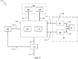
- FIG. 4 is a schematic view of one embodiment of a system 100 for controlling a yaw drive of a wind turbine when a native yaw drive control system is non-operational.
- the system 100 will be described below with reference to the wind turbine 10. Nevertheless, the disclosed system 100 may be used to control a yaw drive of any wind turbine having any suitable wind turbine configuration when an associated native yaw drive control system is non-operational.
- the system 100 may be used when the native control system 50 is non-operational.
- the native control system 50 may be non-operational during various maintenance and repair operations.
- some or all of the native control system 50 may be disabled, such as via a suitable lock-out, tag-out (LOTO) procedure.
- LOTO lock-out, tag-out
- certain components of the native control system 50 may be removed from the wind turbine 10. As such, the native control system 50 is non-operational when the native control system 50 is unable to control the native yaw drive 36.
- the system 100 includes one or more external sensors 102 for detecting one or more parameters indicative of a wind condition experienced by the wind turbine 10.
- the external sensors 102 are electrically and/or communicatively isolated from the native control system 50.
- the external sensors 102 are not reliant on any component of the native control system 50 to support or otherwise facilitate its operation.
- the external sensors 102 may be operable when the native control system 50 is non-operational.
- FIG. 4 illustrates only one external sensor 102, the system 100 may include any suitable number of external sensors 102.
- each external sensor 102 may correspond to one of the native sensors 52.
- the external sensor 102 may provide the same information to the system 100 as the native sensors 52 provides to the native control system 50.
- the external sensor 104 may be configured to detect the same or similar parameters as the native sensor 52.
- the external sensor 102 may be a wind speed sensor 104 that detects a wind speed and/or wind direction experienced by the wind turbine 10 and, more particularly, the nacelle 16.
- the wind speed sensor 104 may be an anemometer, a wind vane, or any other suitable type of sensor for measuring wind speed and/or wind direction.
- the external sensor 102 may be configured to detect a different parameter than the native sensor 52.
- the external sensor 102 may be any suitable type of sensor for measuring any suitable parameter of the wind turbine 10 or the environment proximate to the wind turbine 10.
- the system 100 also includes an external controller 106 configured to be communicatively coupled to one or more components of the system 100 and/or the native yaw drive 36, such as the sensor 102, the yaw adjustment mechanisms 38, and the brake assemblies 48.
- the external controller 106 is electrically and/or communicatively isolated from the native control system 50.
- the external controller 106 is not reliant on any component of the native control system 50 to support or otherwise facilitate its operation.
- the external controller 106 may be operable when the native control system 50 is non-operational.
- the external controller 106 may be communicatively coupled to any suitable number of external sensors 52, yaw adjustment mechanisms 38, and/or brake assemblies 48.
- the external controller 106 may be communicatively coupled to all of the yaw adjustment mechanisms 38 and brake assemblies 48 in the native yaw drive 36.
- the external controller 106 may correspond to any suitable processor-based device, including one or more computing devices. As shown in FIG. 4 , for example, the external controller 106 may include one or more processors 108 and one or more associated memory devices 110 configured to perform a variety of computer-implemented functions (e.g., performing the methods, steps, calculations, and the like disclosed herein). As used herein, the term "processor” refers not only to integrated circuits referred to in the art as being included in a computer, but also refers to a controller, microcontroller, a microcomputer, a programmable logic controller (PLC), an application specific integrated circuit (ASIC), a Field Programmable Gate Array (FPGA), and other programmable circuits.
- PLC programmable logic controller
- ASIC application specific integrated circuit
- FPGA Field Programmable Gate Array
- the memory devices 110 may generally include memory element(s) including, but not limited to, a computer readable medium (e.g., random access memory (RAM)), a computer readable nonvolatile medium (e.g., flash memory), a compact disc-read only memory (CD-ROM), a magneto-optical disk (MOD), a digital versatile disc (DVD), and/or other suitable memory elements or combinations thereof.
- the memory device 110 may store instructions that, when executed by the processor 108, cause the processor 108 to perform various functions, such as controlling the native yaw drive 36.
- the external controller 106 may include variable frequency drive (VFD) architecture.
- VFD variable frequency drive
- the external controller 106 may be configured to generate control signals (e.g., as indicated by arrows 118) having a plurality of voltages and/or frequencies.
- the external controller 106 may be compatible with wind turbines and associated yaw drives having varying operating voltages and/or frequencies.
- the VFD architecture may permit use of the system 100 with wind turbines of different sizes, power outputs, manufacturers, and/or the like.
- the external controller 106 may not include VFD architecture.
- the system 100 may further include a power supply 112 electrically coupled to one or more components of the system 100, such as the external sensor 102 and the external controller 16. More specifically, the power supply 112 may be configured to receive electric power from a suitable power source (e.g., as indicated by arrow 114), such as a portable generator, an electric grid, or the wind turbine 10. The power supply 112 may then be configured to convert or otherwise modify the electric power provided by the power source 114 into a form suitable for use by system 100. For example, the power supply 112 may convert an alternating current power from the electric grid to direct current for use by the external controller 106.
- a suitable power source e.g., as indicated by arrow 114
- the power supply 112 may convert an alternating current power from the electric grid to direct current for use by the external controller 106.
- the power supply 112 may supply the electric power (e.g., as indicated by arrows 116) to the external sensor 102 and/or the external controller 106.
- the power supply 112 is illustrated as providing electric power 116 directly to the external sensor 102, the external sensor 102 may also receive the electric power 116 from the external controller 106.
- the external controller 106 may also provide electrical power to the native yaw drive 36 in the form of control signals 118.
- the system 100 may operate the native yaw drive 36 without the need for power from the native control system 50.
- the power supply 112 may provide the electric power 116 directly to the native yaw drive 36.
- the control signals 118 may actuate a suitable relay or thyristor to control the delivery of electric power to the native yaw drive 36.
- the system 100 may receive electrical power directly from the power source 114.
- the system 100 may include a user interface 120 communicatively coupled to the external controller 106.
- the user interface 120 may be configured to allow interaction between a user and the external controller 106.
- user interface 120 may include one or more input devices 122 (e.g., touchscreens, keypad, touchpad, knobs, buttons, sliders, switches, mouse, microphone, other hardware interfaces, etc.) configured to receive user input.
- the user interface 120 may then transmit the user input to the external controller 106 as user input signals (e.g., as indicated by arrow 124).
- the external controller 106 may provide feedback regarding various operating and/or environmental conditions of the wind turbine 10.
- the external controller 106 may transmit feedback signals (e.g., as indicated by arrow 126) to the user interface 120.
- the user interface 120 may include one or more feedback devices 128 (e.g., display screens, speakers, warning lights, etc.) that communicate the feedback from the external controller 106 to the user.
- the input and feedback devices 122, 128 may be integrated as a single component (e.g., a touchscreen) or be separate and distinct components (e.g., a keypad and a display screen). In alternate embodiments, however, the system 100 may not include the user interface 120.
- the system 100 may generally be configured to be portable.
- the external controller 106 and user interface 120 may be configured to be carried up the tower 12 and placed within the nacelle 16 during maintenance or repair activities.
- a wiring harness (not shown) may communicatively and electrically couple the external controller 106 to the native yaw drive 36.
- the wiring harness may include leads that connect to each native yaw adjustment mechanism 38 and each native brake assembly 48.
- the external controller 106 and user interface 120 may be configured for placement in any suitable location, such as a location on the support surface 14.
- the external sensor 102 may be configured for removable mounting on the exterior of the nacelle 16. In alternate embodiments, however, the wind speed sensor 104 may be mounted in any suitable location, such as a location on the support surface 14.
- the system 100 is configured to control the native yaw drive 36 of the wind turbine 10 when the native control system 50 is non-operational.
- the system 100 may control the yaw angle of wind turbine 10 to prevent undesirable aerodynamic loading on the nacelle 16 during periods when the native control system 50 is unable to operate the native yaw drive 36.
- the external controller 106 may be configured to control the native yaw drive 36 based on measurement signals (e.g., as indicated by arrow 130) received from the external sensor 102.
- the measurement signals 130 may be indicative of the wind conditions experienced by the wind turbine 10.
- the external controller 106 may include a look-up table or suitable mathematical formula stored within the memory 110 that correlates the sensor measurements to a desired yaw angle.
- the external controller 106 is configured to generate the controls signals 118 that control the various components of the native yaw drive 36 to adjust the current yaw angle of the wind turbine 10 to the desired yaw angle.
- the external controller 106 may be configured to transmit the control signals 118 to the yaw adjustment mechanisms 38 and/or the brake assemblies 48, which execute the desired change in yaw angle.
- the controller 106 may be configured to transmit the control signals 118 to the yaw adjustment mechanisms 38 to change the yaw angle of the nacelle 16.
- the external controller 106 may be configured to transmit the control signals 118 to the brake assemblies 48 to stop the rotation of the nacelle 16.
- the system 100 may include a dead band for wind speed or direction such that the external controller 106 may not actuate the native yaw drive 36 when the wind speed or wind direction are in the dead band.
- the external controller 106 may be configured to control the native yaw drive 36 based on other parameters, such as the location of assembly or repair equipment (e.g., cranes, taglines, etc.). For example, the external controller 106 may be configured to prevent the nacelle 16 from contacting the assembly or repair equipment during yaw angle adjustments. In such embodiments, the location of the equipment may be stored in the memory 110 of the external controller 106. Furthermore, the external controller 106 may be configured to prevent operation of the yaw adjustment mechanisms 38 when the brake assemblies 48 are engaged.
- assembly or repair equipment e.g., cranes, taglines, etc.
- the external controller 106 may be configured to prevent the nacelle 16 from contacting the assembly or repair equipment during yaw angle adjustments.
- the location of the equipment may be stored in the memory 110 of the external controller 106.
- the external controller 106 may be configured to prevent operation of the yaw adjustment mechanisms 38 when the brake assemblies 48 are engaged.
- the external controller 106 may be configured to control the native yaw drive 36 based on input signals 124 received from the user interface 120. For example, the user may input (e.g., via the input device 122) a desired yaw angle of the wind turbine 10 to the user interface 120. The user interface 120 may, in turn, transmit the user input signals 124, which are indicative of the desired yaw angle, to the external controller 106. The external controller 106 then controls the native yaw drive 36 accordingly. As such, the user may be able to adjust the yaw angle of the wind turbine 10 to a specific location, such as to align with cranes or other repair equipment. In such embodiments, it is not be necessary to move the equipment to align with the nacelle 16 because the nacelle 16 may be moved to align with the equipment.
- the system 100 may be configured to provide feedback (e.g., via the feedback signals 126 to the feedback device 128) regarding the operation of the system 100, the operation of the wind turbine 10, and/or the environment surrounding the wind turbine 10.
- the system 100 may be configured to audibly or visually alert (e.g., via warning lights, alarms, etc.) the user when a system error or fault occurs in the system 100 and/or the wind turbine 10.
- the system 100 may provide an indication of various current operating parameters (e.g., wind speed, wind direction, yaw angle, etc.) of the system 100 and/or the wind turbine 10.
- the system 100 may provide any suitable form of feedback to the user. In further embodiments, however, the system 100 may not be configured to provide user feedback.
- the system 100 may be configured to provide additional functionality.
- the external controller 106 may be configured to monitor the temperatures of the various components of the native yaw drive 36 relative to a temperature limit. In this respect, the external controller 106 may also be configured to shut down any component of the native yaw drive 36 when its temperature exceeds the temperature limit.
- the system 100 may be configured to unwind the generator 24 when the wind turbine 10 is non-operational to prevent damage to internal power cables. More specifically, in certain instances, the wind may cause the nacelle 16 to rotate relative to the tower 12.
- the external controller 106 may be configured to rotate the nacelle 16 in the opposite direction to unwind the nacelle 16.
Abstract
Description
- The present disclosure generally relates to wind turbines. More particularly, the present disclosure relates to systems for controlling yaw drives of wind turbines when an associated native yaw drive control systems is non-operational.
- Wind power is considered one of the cleanest, most environmentally friendly energy sources presently available, and wind turbines have gained increased attention in this regard. A modern wind turbine typically includes a tower, a nacelle mounted on the tower, a generator positioned in the nacelle, and one or more rotor blades. The one or more rotor blades convert kinetic energy of wind into mechanical energy using known airfoil principles. A drivetrain transmits the mechanical energy from the rotor blades to the generator. The generator then converts the mechanical energy to electrical energy that may be supplied to a utility grid.
- Wind turbines typically include a yaw drive, which adjusts a yaw angle (i.e., the angle of the nacelle relative to the tower) of the wind turbine to properly orient the rotor blades relative to the direction of the wind. In this respect, the yaw drive may include one or more yaw adjustment mechanisms, which rotate the nacelle relative to the tower. Furthermore, the wind turbine includes a yaw drive control system for controlling the operation of the various components of the yaw drive, such as the yaw adjustment mechanisms.
- During maintenance operations, various components of the yaw drive control system (e.g., power supplies, controllers, sensors, etc.) may be disabled, removed from the wind turbine, or otherwise non-operational. When this occurs, the yaw angle of the wind turbine cannot be adjusted. During certain maintenance activities, it may be necessary to move maintenance equipment, such as cranes, relative to the nacelle. The movement of such equipment increases the duration and the cost of the maintenance operation. Furthermore, an inability to adjust the yaw angle of the wind turbine may result in undesirable aerodynamic loading on nacelle and/or rotor.
- Accordingly, a system for controlling a yaw drive of a wind turbine when a native yaw drive control system is non-operational would be welcomed in the art.
- Various aspects and advantages of the technology will be set forth in part in the following description, or may be clear from the description, or may be learned through practice of the technology.
- In one aspect, the present disclosure is directed to a system for controlling a yaw drive of a wind turbine when a native yaw drive control system is non-operational. The system includes an external sensor configured to detect a parameter indicative of a wind condition experienced by the wind turbine. The system also includes an external controller communicatively coupled to the external sensor. The external controller is configured to control the yaw drive based on measurement signals received from the external sensor. The external sensor and the external controller are electrically isolated from the native yaw drive control system.
- In another aspect, the present disclosure is directed to a wind turbine including a tower and a nacelle mounted atop the tower. The wind turbine also includes a rotor rotatably coupled to the nacelle. The rotor includes at least one rotor blade. The wind turbine further includes a yaw drive for adjusting a yaw angle of the nacelle and a native yaw drive control system. Furthermore, the wind turbine includes a system for controlling the yaw drive of the wind turbine when the native yaw drive control system is non-operational. The system includes an external controller communicatively coupled to the external sensor. The external controller is configured to control the yaw drive based on received measurement signals or received input signals. The external controller is electrically isolated from the native yaw drive control system.
- Various features, aspects and advantages of the present technology will become better understood with reference to the following description and appended claims. The accompanying drawings, which are incorporated in and constitute a part of this specification, illustrate embodiments of the technology and, together with the description, serve to explain the principles of the technology.
- In the drawings:
-
FIG. 1 is a perspective view of an exemplary wind turbine in accordance with embodiments of the present disclosure; -
FIG. 2 is a perspective, internal view of an exemplary nacelle of a wind turbine in accordance with embodiments of the present disclosure; -
FIG. 3 is a schematic view of one embodiment of an exemplary native yaw drive control system of a wind turbine in accordance with embodiments of the present disclosure; -
FIG. 4 is a schematic view of one embodiment of a system for controlling a yaw drive of a wind turbine when a native yaw drive control system is non-operational in accordance with embodiments of the present disclosure; and -
FIG. 5 is a side view of one embodiment of an external sensor of a system for controlling a yaw drive of a wind turbine when a native yaw drive control system is non-operational, illustrating the external sensor mounted to a nacelle of a wind turbine in accordance with embodiments of the present disclosure. - Repeat use of reference characters in the present specification and drawings is intended to represent the same or analogous features or elements of the present technology.
- Reference will now be made in detail to present embodiments of the technology, one or more examples of which are illustrated in the accompanying drawings. The detailed description uses numerical and letter designations to refer to features in the drawings. Like or similar designations in the drawings and description have been used to refer to like or similar parts of the technology. As used herein, the terms "first", "second", and "third" may be used interchangeably to distinguish one component from another and are not intended to signify location or importance of the individual components.
- Each example is provided by way of explanation of the technology, not limitation of the technology. In fact, it will be apparent to those skilled in the art that modifications and variations can be made in the present technology without departing from the scope or spirit thereof. For instance, features illustrated or described as part of one embodiment may be used on another embodiment to yield a still further embodiment. Thus, it is intended that the present technology covers such modifications and variations as come within the scope of the appended claims and their equivalents.
- Referring now to the drawings,
FIG. 1 is a perspective view of anexemplary wind turbine 10. As shown, thewind turbine 10 generally includes atower 12 extending from asupport surface 14, anacelle 16 mounted on thetower 12, and arotor 18 coupled to thenacelle 16. Therotor 18 includes arotatable hub 20 and at least onerotor blade 22 coupled to and extending outward from thehub 20. For example, in the embodiment shown inFIG. 1 , therotor 18 includes threerotor blades 22. In alternative embodiments, however, therotor 18 may include more or less than threerotor blades 22. Eachrotor blade 22 may be spaced about thehub 20 to facilitate rotation of therotor 18 to convert kinetic energy from the wind into usable rotational, mechanical energy. Agenerator 24 positioned in thenacelle 16 may generate electrical power from the rotational energy of therotor 18. - Referring now to
FIG. 2 , adrivetrain 26 rotatably couples therotor 18 to thegenerator 24. As shown, thedrivetrain 26 may include arotor shaft 28, which rotatably couples thehub 20 of therotor 18 to agearbox 30. Thegearbox 30 may be supported by and coupled to abedplate 32 within thenacelle 16. Thedrivetrain 26 may also include agenerator shaft 34, which rotatably couples thegearbox 30 to thegenerator 24. In this respect, rotation of therotor 18 drives thegenerator 24. More specifically, therotor shaft 28 may provide a low speed, high torque input to thegearbox 30 in response to rotation of therotor blades 22 and thehub 20. Thegearbox 30 may then convert the low speed, high torque input to a high speed, low torque output to drive thegenerator shaft 34 and, thus, thegenerator 24. In alternate embodiments, however, thegenerator 24 may be directly rotatably coupled to therotor shaft 28 in a direct-drive configuration. - The
wind turbine 10 may also include anative yaw drive 36 for adjusting a yaw angle of the nacelle 16 (i.e., the angular orientation of thenacelle 16 relative to the tower 12). In particular, thenacelle 16 may be rotatably coupled to thetower 12 by a yaw bearing (not shown). As such, thenative yaw drive 36 may include one or more nativeyaw adjustment mechanisms 38, which rotate thenacelle 16 about a yaw axis 40 (FIG. 1 ) relative to thetower 12 to adjust the yaw angle of thenacelle 16. AlthoughFIG. 2 illustrates twoyaw adjustment mechanisms 38, thewind turbine 10 may include any suitable number ofyaw adjustment mechanisms 38, such as a singleyaw adjustment mechanism 38 or more than twoyaw adjustment mechanisms 38. For example, certain embodiments of thenative yaw drive 36 may include fouryaw adjustment mechanisms 38. -
FIG. 2 illustrates an exemplary embodiment of theyaw adjustment mechanisms 38. More specifically, eachyaw adjustment mechanism 38 may include anelectric motor 42 mounted to and/or through thebedplate 32. Eachelectric motor 42 may include apinion gear 44 coupled thereto, which engages atower ring gear 46 coupled to thetower 12. During operation of theyaw adjustment mechanisms 38, theelectric motors 42 rotate the corresponding pinion gears 44, which rotate thetower ring gear 46. The rotation of the pinion gears 44 relative to thetower ring gear 46 causes thenacelle 16 to rotate about the yaw axis 40 (FIG. 1 ). In alternate embodiments, theyaw adjustment mechanisms 38 may include any suitable type of actuator and/or any suitable structure or mechanism for transmitting movement between thetower 12 and thenacelle 16. - The
native yaw drive 36 may also include one or morenative brake assemblies 48 for controlling the rotation of thenacelle 16 about theyaw axis 40. For example, as shown in the illustrated embodiment, thebrake assemblies 48 may be mounted to and/or through thebedplate 32. As such, eachbrake assembly 48 may frictionally engage thetower ring gear 46 or another suitable friction surface of thewind turbine 10 to stop, slow, and/or otherwise control the rotation of thenacelle 16 about theyaw axis 40. Thewind turbine 10 may include any suitable number ofbrake assemblies 48. For instance, in an exemplary embodiment, thewind turbine 10 may include between twelve and twentybrake assemblies 48. In other embodiments, however, thewind turbine 10 may include less than twelvebrake assemblies 48 or more than twentybrake assemblies 48. - Referring now to
FIG. 3 , thewind turbine 10 may include a native yaw drive control system 50 ("native control system 50") for controlling the operation of one or more components of thenative yaw drive 36, such as theyaw adjustment mechanisms 38 and/or thebrake assemblies 48. In general, thenative control system 50 controls thenative yaw drive 36 during operation of thewind turbine 10, such as when thewind turbine 10 is generating power or otherwise not disabled or partially disabled for maintenance or repair operations. In the embodiment shown inFIG. 3 , for example, all of the components of thenative control system 50 may be located within thewind turbine 10. In alternative embodiments, however, some of the components of thenative control system 50 maybe positioned outside of thewind turbine 10. - As shown, the
native control system 50 may include one or morenative sensors 52 for detecting one or more parameters indicative of a wind condition experienced by thewind turbine 10. AlthoughFIG. 3 illustrates only onenative sensor 52, thenative control system 50 may include any suitable number ofnative sensors 52. For example, in several embodiments, thenative sensor 52 may be awind speed sensor 54 shown inFIG. 2 . Specifically, thewind speed sensor 54 detects a wind speed and/or direction experienced by thewind turbine 10 and, more particularly, thenacelle 16. In this respect, thewind speed sensor 54 may be an anemometer, a wind vane, or any other suitable type of sensor for measuring wind speed and/or direction. In some embodiments, thewind speed sensor 54 may be mounted to the exterior of thenacelle 16. In alternative embodiments, however, thenative sensor 52 may be any suitable type of sensor for measuring any suitable parameter of thewind turbine 10 or the environment proximate to thewind turbine 10. - The
native control system 50 may also include anative controller 56 communicatively coupled to one or more components of thenative control system 50 and/or thenative yaw drive 36, such as thesensors 52, theyaw adjustment mechanisms 38, and thebrake assemblies 48. AlthoughFIG. 3 illustrates thenative controller 56 as being communicatively coupled to only onenative sensor 52, oneyaw adjustment mechanism 38, and onebrake assembly 48, thenative controller 56 may be communicatively coupled to any suitable number ofnative sensors 52,yaw adjustment mechanisms 38, and/orbrake assemblies 48. For example, in some embodiments, thenative controller 56 may be communicatively coupled to all of theyaw adjustment mechanisms 38 andbrake assemblies 48 in thenative yaw drive 36. As shown inFIG. 2 , for example, thenative controller 56 may be disposed within acontrol cabinet 58 mounted within a portion of thenacelle 16. In alternate embodiments, however, thenative controller 56 maybe disposed at any location on or in thewind turbine 10, at any location on thesupport surface 14, or any other suitable location. - In general, the
native controller 56 may correspond to any suitable processor-based device, including one or more computing devices. As shown inFIG. 3 , for example, thenative controller 56 may include one ormore processors 60 and one or more associatedmemory devices 62 configured to perform a variety of computer-implemented functions (e.g., performing the methods, steps, calculations, and the like disclosed herein). As used herein, the term "processor" refers not only to integrated circuits referred to in the art as being included in a computer, but also refers to a controller, microcontroller, a microcomputer, a programmable logic controller (PLC), an application specific integrated circuit (ASIC), a Field Programmable Gate Array (FPGA), and other programmable circuits. Additionally, thememory devices 62 may generally include memory element(s) including, but not limited to, a computer readable medium (e.g., random access memory (RAM)), a computer readable nonvolatile medium (e.g., flash memory), a compact disc-read only memory (CD-ROM), a magneto-optical disk (MOD), a digital versatile disc (DVD), and/or other suitable memory elements or combinations thereof. Thememory device 62 may store instructions that, when executed by theprocessor 60, cause theprocessor 60 to perform various functions, such as controlling thenative yaw drive 36. - As mentioned above, the
native control system 50 controls the operation of thenative yaw drive 36 during operation of thewind turbine 10. For example, in the embodiment shown inFIG. 3 , thenative controller 56 may receive measurement signals (e.g., as indicated by arrow 64) from thenative sensor 52 during operation of thewind turbine 10. Based on these measurement signals 64, thenative controller 56 may transmit controls signals (e.g., as indicated by arrow 66) to theyaw adjustment mechanism 38 and thebrake assembly 48 for controlling the yaw angle of thewind turbine 10. In this respect, thenative control system 50 may further include the necessary communication interfaces, circuitry, and/or other electrical/communication devices necessary to facilitate such operation of thenative yaw drive 36. - In alternative embodiments, the
native control system 50 may include other components in addition to thenative sensor 52, thenative controller 56, and the associated communication interfaces and circuitry. Furthermore, thenative control system 50 may operate in any suitable manner that permits control of the yaw angle of thewind turbine 10. -
FIG. 4 is a schematic view of one embodiment of asystem 100 for controlling a yaw drive of a wind turbine when a native yaw drive control system is non-operational. In general, thesystem 100 will be described below with reference to thewind turbine 10. Nevertheless, the disclosedsystem 100 may be used to control a yaw drive of any wind turbine having any suitable wind turbine configuration when an associated native yaw drive control system is non-operational. - As mentioned above, the
system 100 may be used when thenative control system 50 is non-operational. For example, thenative control system 50 may be non-operational during various maintenance and repair operations. In such instances, some or all of thenative control system 50 may be disabled, such as via a suitable lock-out, tag-out (LOTO) procedure. Furthermore, in some maintenance or repair activities, certain components of thenative control system 50 may be removed from thewind turbine 10. As such, thenative control system 50 is non-operational when thenative control system 50 is unable to control thenative yaw drive 36. - As shown in
FIG. 4 , thesystem 100 includes one or moreexternal sensors 102 for detecting one or more parameters indicative of a wind condition experienced by thewind turbine 10. In general, theexternal sensors 102 are electrically and/or communicatively isolated from thenative control system 50. As such, theexternal sensors 102 are not reliant on any component of thenative control system 50 to support or otherwise facilitate its operation. In this respect, theexternal sensors 102 may be operable when thenative control system 50 is non-operational. AlthoughFIG. 4 illustrates only oneexternal sensor 102, thesystem 100 may include any suitable number ofexternal sensors 102. - In several embodiments, each
external sensor 102 may correspond to one of thenative sensors 52. As such, theexternal sensor 102 may provide the same information to thesystem 100 as thenative sensors 52 provides to thenative control system 50. In this respect, theexternal sensor 104 may be configured to detect the same or similar parameters as thenative sensor 52. For example, as illustrated inFIG. 5 , theexternal sensor 102 may be awind speed sensor 104 that detects a wind speed and/or wind direction experienced by thewind turbine 10 and, more particularly, thenacelle 16. As such, thewind speed sensor 104 may be an anemometer, a wind vane, or any other suitable type of sensor for measuring wind speed and/or wind direction. In alternate embodiments, theexternal sensor 102 may be configured to detect a different parameter than thenative sensor 52. In further embodiments, theexternal sensor 102 may be any suitable type of sensor for measuring any suitable parameter of thewind turbine 10 or the environment proximate to thewind turbine 10. - The
system 100 also includes anexternal controller 106 configured to be communicatively coupled to one or more components of thesystem 100 and/or thenative yaw drive 36, such as thesensor 102, theyaw adjustment mechanisms 38, and thebrake assemblies 48. In general, theexternal controller 106 is electrically and/or communicatively isolated from thenative control system 50. As such, theexternal controller 106 is not reliant on any component of thenative control system 50 to support or otherwise facilitate its operation. In this respect, theexternal controller 106 may be operable when thenative control system 50 is non-operational. AlthoughFIG. 4 illustrates theexternal controller 106 as being communicatively coupled to only oneexternal sensor 102, oneyaw adjustment mechanism 38, and onebrake assembly 48, theexternal controller 106 may be communicatively coupled to any suitable number ofexternal sensors 52,yaw adjustment mechanisms 38, and/orbrake assemblies 48. In particular embodiments, theexternal controller 106 may be communicatively coupled to all of theyaw adjustment mechanisms 38 andbrake assemblies 48 in thenative yaw drive 36. - In general, the
external controller 106 may correspond to any suitable processor-based device, including one or more computing devices. As shown inFIG. 4 , for example, theexternal controller 106 may include one ormore processors 108 and one or more associatedmemory devices 110 configured to perform a variety of computer-implemented functions (e.g., performing the methods, steps, calculations, and the like disclosed herein). As used herein, the term "processor" refers not only to integrated circuits referred to in the art as being included in a computer, but also refers to a controller, microcontroller, a microcomputer, a programmable logic controller (PLC), an application specific integrated circuit (ASIC), a Field Programmable Gate Array (FPGA), and other programmable circuits. Additionally, thememory devices 110 may generally include memory element(s) including, but not limited to, a computer readable medium (e.g., random access memory (RAM)), a computer readable nonvolatile medium (e.g., flash memory), a compact disc-read only memory (CD-ROM), a magneto-optical disk (MOD), a digital versatile disc (DVD), and/or other suitable memory elements or combinations thereof. Thememory device 110 may store instructions that, when executed by theprocessor 108, cause theprocessor 108 to perform various functions, such as controlling thenative yaw drive 36. - In several embodiments, the
external controller 106 may include variable frequency drive (VFD) architecture. In such embodiments, theexternal controller 106 may be configured to generate control signals (e.g., as indicated by arrows 118) having a plurality of voltages and/or frequencies. In this respect, theexternal controller 106 may be compatible with wind turbines and associated yaw drives having varying operating voltages and/or frequencies. As such, the VFD architecture may permit use of thesystem 100 with wind turbines of different sizes, power outputs, manufacturers, and/or the like. In alternative embodiments, theexternal controller 106 may not include VFD architecture. - The
system 100 may further include apower supply 112 electrically coupled to one or more components of thesystem 100, such as theexternal sensor 102 and theexternal controller 16. More specifically, thepower supply 112 may be configured to receive electric power from a suitable power source (e.g., as indicated by arrow 114), such as a portable generator, an electric grid, or thewind turbine 10. Thepower supply 112 may then be configured to convert or otherwise modify the electric power provided by thepower source 114 into a form suitable for use bysystem 100. For example, thepower supply 112 may convert an alternating current power from the electric grid to direct current for use by theexternal controller 106. As shown, thepower supply 112 may supply the electric power (e.g., as indicated by arrows 116) to theexternal sensor 102 and/or theexternal controller 106. Although thepower supply 112 is illustrated as providingelectric power 116 directly to theexternal sensor 102, theexternal sensor 102 may also receive theelectric power 116 from theexternal controller 106. Theexternal controller 106 may also provide electrical power to thenative yaw drive 36 in the form of control signals 118. As such, thesystem 100 may operate thenative yaw drive 36 without the need for power from thenative control system 50. In alternate embodiments, thepower supply 112 may provide theelectric power 116 directly to thenative yaw drive 36. As such, the control signals 118 may actuate a suitable relay or thyristor to control the delivery of electric power to thenative yaw drive 36. In further embodiments, thesystem 100 may receive electrical power directly from thepower source 114. - Furthermore, the
system 100 may include auser interface 120 communicatively coupled to theexternal controller 106. In general, theuser interface 120 may be configured to allow interaction between a user and theexternal controller 106. For example,user interface 120 may include one or more input devices 122 (e.g., touchscreens, keypad, touchpad, knobs, buttons, sliders, switches, mouse, microphone, other hardware interfaces, etc.) configured to receive user input. Theuser interface 120 may then transmit the user input to theexternal controller 106 as user input signals (e.g., as indicated by arrow 124). Furthermore, in some embodiments, theexternal controller 106 may provide feedback regarding various operating and/or environmental conditions of thewind turbine 10. In such instances, theexternal controller 106 may transmit feedback signals (e.g., as indicated by arrow 126) to theuser interface 120. In this respect, theuser interface 120 may include one or more feedback devices 128 (e.g., display screens, speakers, warning lights, etc.) that communicate the feedback from theexternal controller 106 to the user. The input andfeedback devices system 100 may not include theuser interface 120. - In several embodiments, the
system 100 may generally be configured to be portable. For example, theexternal controller 106 anduser interface 120 may be configured to be carried up thetower 12 and placed within thenacelle 16 during maintenance or repair activities. In such embodiments, a wiring harness (not shown) may communicatively and electrically couple theexternal controller 106 to thenative yaw drive 36. For example, the wiring harness may include leads that connect to each nativeyaw adjustment mechanism 38 and eachnative brake assembly 48. Although, theexternal controller 106 anduser interface 120 may be configured for placement in any suitable location, such as a location on thesupport surface 14. Furthermore, as shown inFIG. 5 , theexternal sensor 102 may be configured for removable mounting on the exterior of thenacelle 16. In alternate embodiments, however, thewind speed sensor 104 may be mounted in any suitable location, such as a location on thesupport surface 14. - As mentioned above, the
system 100 is configured to control thenative yaw drive 36 of thewind turbine 10 when thenative control system 50 is non-operational. In this respect, thesystem 100 may control the yaw angle ofwind turbine 10 to prevent undesirable aerodynamic loading on thenacelle 16 during periods when thenative control system 50 is unable to operate thenative yaw drive 36. More specifically, theexternal controller 106 may be configured to control thenative yaw drive 36 based on measurement signals (e.g., as indicated by arrow 130) received from theexternal sensor 102. In some embodiments, the measurement signals 130 may be indicative of the wind conditions experienced by thewind turbine 10. Theexternal controller 106 may include a look-up table or suitable mathematical formula stored within thememory 110 that correlates the sensor measurements to a desired yaw angle. When the desired yaw angle is different than the current yaw angle, theexternal controller 106 is configured to generate the controls signals 118 that control the various components of thenative yaw drive 36 to adjust the current yaw angle of thewind turbine 10 to the desired yaw angle. As such, theexternal controller 106 may be configured to transmit the control signals 118 to theyaw adjustment mechanisms 38 and/or thebrake assemblies 48, which execute the desired change in yaw angle. For example, thecontroller 106 may be configured to transmit the control signals 118 to theyaw adjustment mechanisms 38 to change the yaw angle of thenacelle 16. When the current yaw angle is the same as the desired yaw angle, theexternal controller 106 may be configured to transmit the control signals 118 to thebrake assemblies 48 to stop the rotation of thenacelle 16. In some embodiments, thesystem 100 may include a dead band for wind speed or direction such that theexternal controller 106 may not actuate thenative yaw drive 36 when the wind speed or wind direction are in the dead band. - In some embodiments, the
external controller 106 may be configured to control thenative yaw drive 36 based on other parameters, such as the location of assembly or repair equipment (e.g., cranes, taglines, etc.). For example, theexternal controller 106 may be configured to prevent thenacelle 16 from contacting the assembly or repair equipment during yaw angle adjustments. In such embodiments, the location of the equipment may be stored in thememory 110 of theexternal controller 106. Furthermore, theexternal controller 106 may be configured to prevent operation of theyaw adjustment mechanisms 38 when thebrake assemblies 48 are engaged. - The
external controller 106 may be configured to control thenative yaw drive 36 based oninput signals 124 received from theuser interface 120. For example, the user may input (e.g., via the input device 122) a desired yaw angle of thewind turbine 10 to theuser interface 120. Theuser interface 120 may, in turn, transmit the user input signals 124, which are indicative of the desired yaw angle, to theexternal controller 106. Theexternal controller 106 then controls thenative yaw drive 36 accordingly. As such, the user may be able to adjust the yaw angle of thewind turbine 10 to a specific location, such as to align with cranes or other repair equipment. In such embodiments, it is not be necessary to move the equipment to align with thenacelle 16 because thenacelle 16 may be moved to align with the equipment. - In certain embodiments, the
system 100 may be configured to provide feedback (e.g., via the feedback signals 126 to the feedback device 128) regarding the operation of thesystem 100, the operation of thewind turbine 10, and/or the environment surrounding thewind turbine 10. For example, thesystem 100 may be configured to audibly or visually alert (e.g., via warning lights, alarms, etc.) the user when a system error or fault occurs in thesystem 100 and/or thewind turbine 10. Furthermore, thesystem 100 may provide an indication of various current operating parameters (e.g., wind speed, wind direction, yaw angle, etc.) of thesystem 100 and/or thewind turbine 10. In alternative embodiments, thesystem 100 may provide any suitable form of feedback to the user. In further embodiments, however, thesystem 100 may not be configured to provide user feedback. - In further embodiments, the
system 100 may be configured to provide additional functionality. For example, theexternal controller 106 may be configured to monitor the temperatures of the various components of thenative yaw drive 36 relative to a temperature limit. In this respect, theexternal controller 106 may also be configured to shut down any component of thenative yaw drive 36 when its temperature exceeds the temperature limit. Additionally, thesystem 100 may be configured to unwind thegenerator 24 when thewind turbine 10 is non-operational to prevent damage to internal power cables. More specifically, in certain instances, the wind may cause thenacelle 16 to rotate relative to thetower 12. When thenacelle 16 rotates relative to the nacelle more than a predetermined number of consecutive revolutions (e.g., three revolutions) in one direction (e.g., clockwise or counterclockwise), theexternal controller 106 may be configured to rotate thenacelle 16 in the opposite direction to unwind thenacelle 16. - This written description uses examples to disclose the technology, including the best preferred, and also to enable any person skilled in the art to practice the technology, including making and using any devices or systems and performing any incorporated methods. The patentable scope of the technology is defined by the claims, and may include other examples that occur to those skilled in the art. Such other examples are intended to be within the scope of the claims if they include structural elements that do not differ from the literal language of the claims, or if they include equivalent structural elements with insubstantial differences from the literal language of the claims.
- Various aspects and embodiments of the present invention are defined by the following numbered clauses:
- 1. A system for controlling a yaw drive of a wind turbine when a native yaw drive control system is non-operational, the system comprising:
- an external sensor configured to detect a parameter indicative of a wind condition experienced by the wind turbine; and,
- an external controller communicatively coupled to the external sensor, the external controller being configured to control the yaw drive based on measurement signals received from the external sensor,
- wherein the external sensor and the external controller are electrically isolated from the native yaw drive control system.
- 2. The system of clause 1, further comprising:
a power supply configured to provide power to at least one of the external sensor, the external controller, or the yaw drive, the power supply being electrically isolated from the native yaw drive control system. - 3. The system of any preceding clause, further comprising:
a user interface communicatively coupled to the external controller. - 4. The system of any preceding clause, wherein the external controller is configured to control the yaw drive based on input signals received from the user interface.
- 5. The system of any preceding clause, wherein the external controller is configured to control one or more yaw adjustment mechanisms of the yaw drive based on measurement signals received from the external sensor.
- 6. The system of any preceding clause, wherein the external controller is configured to control one or more yaw brakes of the yaw drive based on measurement signals received from the external sensor.
- 7. The system of any preceding clause, wherein the external controller comprises a variable frequency drive architecture.
- 8. The system of any preceding clause, wherein the external controller is configured to generate control signals having a plurality of frequencies or voltages.
- 9. The system of any preceding clause, wherein the external controller is configured to control the yaw drive based on a location of assembly or repair equipment.
- 10. The system of any preceding clause, wherein the wind condition is a wind direction or a wind speed.
- 11. A wind turbine, comprising:
- a tower;
- a nacelle mounted atop the tower;
- a rotor rotatably coupled to the nacelle, the rotor comprising at least one rotor blade;
- a yaw drive for adjusting a yaw angle of the nacelle;
- a native yaw drive control system; and,
- a system for controlling the yaw drive when the native yaw drive control system is non-operational, the system comprising:
- an external controller communicatively coupled to the yaw drive, the external controller being configured to control the yaw drive based on received measurement signals or received input signals,
- wherein the external controller is electrically isolated from the native yaw drive control system.
- 12. The wind turbine of any preceding clause, further comprising:
an external sensor communicatively coupled to the external controller and electrically isolated from the native yaw control system, the external sensor being configured to detect a parameter indicative of a wind condition experienced by the wind turbine and transmit measurement signals to the external controller. - 13. The wind turbine of any preceding clause, further comprising:
a power supply configured to provide power to at least one of the external sensor, the external controller, or the yaw drive, the power supply being electrically isolated from the native yaw drive control system. - 14. The wind turbine of any preceding clause, further comprising:
a user interface communicatively coupled to the external controller, the external controller being configured to control the yaw drive based on input signals received from the user interface. - 15. The wind turbine of any preceding clause, wherein the external controller is configured to control one or more yaw adjustment mechanisms of the yaw drive and one or more yaw brakes of the yaw drive based on the received measurement signals or input signals.
- 16. The wind turbine of any preceding clause, wherein the external controller comprises a variable frequency drive architecture.
- 17. The wind turbine of any preceding clause, wherein the external controller is configured to generate control signals having a plurality of frequencies or voltages.
- 18. The wind turbine of any preceding clause, wherein the external controller is configured to control the yaw drive based on a location of assembly or repair equipment.
- 19. The wind turbine of any preceding clause, wherein the wind condition is a wind direction or a wind speed.
- 20. The wind turbine of any preceding clause, wherein the external sensor is configured for mounting on a nacelle of the wind turbine.
Claims (15)
- A system (100) for controlling a yaw drive (36) of a wind turbine (10) when a native yaw drive control system (50) is non-operational, the system (100) comprising:an external sensor (102) configured to detect a parameter indicative of a wind condition experienced by the wind turbine (10); and,an external controller (106) communicatively coupled to the external sensor (102), the external controller (106) being configured to control the yaw drive (36) based on measurement signals (130) received from the external sensor (102),wherein the external sensor (102) and the external controller (106) are electrically isolated from the native yaw drive control system (50).
- The system (100) of claim 1, further comprising:a power supply (112) configured to provide power to at least one of the external sensor (102), the external controller (106), or the yaw drive (36), the power supply (112) being electrically isolated from the native yaw drive control system (50).
- The system (100) of any preceding claim, further comprising:a user interface (120) communicatively coupled to the external controller (106).
- The system (100) of claim 3, wherein the external controller (106) is configured to control the yaw drive (36) based on input signals (124) received from the user interface (120).
- The system (100) of any preceding claim, wherein the external controller (106) is configured to control one or more yaw adjustment mechanisms (38) of the yaw drive (36) based on measurement signals (130) received from the external sensor (102).
- The system (100) of any preceding claim, wherein the external controller (106) is configured to control one or more yaw brakes (48) of the yaw drive (36) based on measurement signals (130) received from the external sensor (102).
- The system (100) of any preceding claim, wherein the external controller (106) comprises a variable frequency drive architecture.
- The system (100) of claim 7, wherein the external controller (106) is configured to generate control signals (118) having a plurality of frequencies or voltages.
- The system (100) of any preceding claim, wherein the external controller (106) is configured to control the yaw drive (36) based on a location of assembly or repair equipment.
- The system (100) of any preceding claim, wherein the wind condition is a wind direction or a wind speed.
- A wind turbine (10), comprising:a tower (12);a nacelle (16) mounted atop the tower (12);a rotor (18) rotatably coupled to the nacelle (16), the rotor (18) comprising at least one rotor blade (22);a yaw drive (36) for adjusting a yaw angle of the nacelle (16);a native yaw drive control system (50); anda system (100) for controlling the yaw drive (36) when the native yaw drive control system (50) is non-operational, the system (100) comprising:an external controller (106) communicatively coupled to the yaw drive (36), the external controller (106) being configured to control the yaw drive (36) based on received measurement signals (130) or received input signals,wherein the external controller (106) is electrically isolated from the native yaw drive control system (50).
- The wind turbine (10) of claim 11, further comprising:an external sensor (102) communicatively coupled to the external controller (106) and electrically isolated from the native yaw control system (100), the external sensor (102) being configured to detect a parameter indicative of a wind condition experienced by the wind turbine (10) and transmit measurement signals (130) to the external controller (106).
- The wind turbine (10) of claim 11 or 12, further comprising:a power supply (112) configured to provide power to at least one of the external sensor (102), the external controller (106), or the yaw drive (36), the power supply (112) being electrically isolated from the native yaw drive control system (50).
- The wind turbine (10) of any of claims 11 to 13, further comprising:a user interface (120) communicatively coupled to the external controller (106), the external controller (106) being configured to control the yaw drive (36) based on input signals (124) received from the user interface (120).
- The wind turbine (10) of any of claims 11 to 14, wherein the external controller (106) is configured to control one or more yaw adjustment mechanisms (38) of the yaw drive (36) and one or more yaw brakes (48) of the yaw drive (36) based on the received measurement signals (130) or input signals (124).
Applications Claiming Priority (1)
| Application Number | Priority Date | Filing Date | Title |
|---|---|---|---|
| US15/682,667 US10598148B2 (en) | 2017-08-22 | 2017-08-22 | System for controlling a yaw drive of a wind turbine when a native yaw drive control system is non-operational |
Publications (2)
| Publication Number | Publication Date |
|---|---|
| EP3450747A1 true EP3450747A1 (en) | 2019-03-06 |
| EP3450747B1 EP3450747B1 (en) | 2021-06-16 |
Family
ID=63293993
Family Applications (1)
| Application Number | Title | Priority Date | Filing Date |
|---|---|---|---|
| EP18189148.2A Active EP3450747B1 (en) | 2017-08-22 | 2018-08-15 | System for controlling a yaw drive of a wind turbine when a native yaw drive control system is non-operational |
Country Status (5)
| Country | Link |
|---|---|
| US (1) | US10598148B2 (en) |
| EP (1) | EP3450747B1 (en) |
| JP (1) | JP7229699B2 (en) |
| DK (1) | DK3450747T3 (en) |
| ES (1) | ES2887791T3 (en) |
Citations (3)
| Publication number | Priority date | Publication date | Assignee | Title |
|---|---|---|---|---|
| US20120073134A1 (en) * | 2010-09-23 | 2012-03-29 | Northern Power Systems, Inc. | Method and System for Servicing a Horizontal-Axis Wind Power Unit |
| EP2738382A2 (en) * | 2012-11-29 | 2014-06-04 | General Electric Company | System and method for providing yaw backup to a wind farm |
| EP3128170A1 (en) * | 2015-08-06 | 2017-02-08 | Nordex Energy GmbH | Wind power facility with a yaw drive |
Family Cites Families (18)
| Publication number | Priority date | Publication date | Assignee | Title |
|---|---|---|---|---|
| EP2017468A1 (en) * | 2007-07-20 | 2009-01-21 | Siemens Aktiengesellschaft | Method for wind turbine yaw control |
| CA2693752A1 (en) | 2010-02-18 | 2011-08-18 | Mitsubishi Heavy Industries, Ltd. | Handy terminal for wind turbine generator |
| EP2402597B1 (en) * | 2010-06-29 | 2016-08-03 | Siemens Aktiengesellschaft | Wind turbine yaw system and method of controlling the same |
| JP2013011200A (en) | 2011-06-28 | 2013-01-17 | Mitsubishi Heavy Ind Ltd | Operation monitoring system, operation monitoring method, and program |
| ES2596253T3 (en) * | 2011-11-24 | 2017-01-05 | Vestas Wind Systems A/S | A yaw system comprising a preload mechanism |
| EP2653721B1 (en) * | 2012-04-17 | 2020-07-29 | Siemens Gamesa Renewable Energy A/S | Wind turbine measurement system |
| DE102013101012A1 (en) * | 2013-02-01 | 2014-08-07 | 2-B Energy Holding B.V. | Control device for a yaw system of a wind turbine |
| CN104018986B (en) | 2013-02-28 | 2017-03-29 | 国际商业机器公司 | Method and apparatus for controlling blower fan |
| US20150086357A1 (en) * | 2013-09-24 | 2015-03-26 | General Electric Company | Wind turbine and method for adjusting yaw bias in wind turbine |
| US9920742B2 (en) * | 2014-02-20 | 2018-03-20 | General Electric Company | Dynamic cut-in wind speed for wind turbines |
| JP6247957B2 (en) * | 2014-02-26 | 2017-12-13 | 三菱重工業株式会社 | Yaw control system and yaw control method for wind turbine generator |
| US9631606B2 (en) * | 2014-04-14 | 2017-04-25 | General Electric Company | System and method for thrust-speed control of a wind turbine |
| US9261075B2 (en) * | 2014-04-23 | 2016-02-16 | General Electric Company | Wind turbine shadow flicker protection system having a driving mechanism allowing a single light sensor to receive light at different times and directions |
| US9745958B2 (en) * | 2014-06-30 | 2017-08-29 | General Electric Company | Method and system for managing loads on a wind turbine |
| ES2702475T3 (en) * | 2014-09-29 | 2019-03-01 | Vestas Wind Sys As | Verification of wind turbine gondola yaw position sensor and yaw control system |
| US9567978B2 (en) * | 2014-10-27 | 2017-02-14 | General Electric Company | System and method for adaptive rotor imbalance control |
| JP6534569B2 (en) | 2015-07-06 | 2019-06-26 | Ntn株式会社 | Wind power system |
| CN106930899B (en) | 2016-06-06 | 2018-06-26 | 北京普华亿能风电技术有限公司 | The electric power system and method for supplying power to of a kind of yaw motor in wind turbine |
-
2017
- 2017-08-22 US US15/682,667 patent/US10598148B2/en active Active
-
2018
- 2018-08-15 EP EP18189148.2A patent/EP3450747B1/en active Active
- 2018-08-15 ES ES18189148T patent/ES2887791T3/en active Active
- 2018-08-15 DK DK18189148.2T patent/DK3450747T3/en active
- 2018-08-22 JP JP2018155154A patent/JP7229699B2/en active Active
Patent Citations (3)
| Publication number | Priority date | Publication date | Assignee | Title |
|---|---|---|---|---|
| US20120073134A1 (en) * | 2010-09-23 | 2012-03-29 | Northern Power Systems, Inc. | Method and System for Servicing a Horizontal-Axis Wind Power Unit |
| EP2738382A2 (en) * | 2012-11-29 | 2014-06-04 | General Electric Company | System and method for providing yaw backup to a wind farm |
| EP3128170A1 (en) * | 2015-08-06 | 2017-02-08 | Nordex Energy GmbH | Wind power facility with a yaw drive |
Also Published As
| Publication number | Publication date |
|---|---|
| US20190063402A1 (en) | 2019-02-28 |
| JP2019039430A (en) | 2019-03-14 |
| DK3450747T3 (en) | 2021-09-13 |
| US10598148B2 (en) | 2020-03-24 |
| JP7229699B2 (en) | 2023-02-28 |
| ES2887791T3 (en) | 2021-12-27 |
| EP3450747B1 (en) | 2021-06-16 |
Similar Documents
| Publication | Publication Date | Title |
|---|---|---|
| WO2012129721A1 (en) | Method for adjusting power output of wind turbine | |
| US10781795B2 (en) | Method and system for detecting a mass imbalance in a wind turbine rotor | |
| US8303251B2 (en) | Systems and methods for assembling a pitch assembly for use in a wind turbine | |
| US10935001B2 (en) | System and method for monitoring wear on a gearbox of a wind turbine | |
| EP3619423B1 (en) | System and method for reducing wind turbine rotor blade loads | |
| EP3067554B1 (en) | Wind turbine control using signal controller | |
| ES2805775T3 (en) | Autonomous rotor orientation control for a wind turbine | |
| JP2022089163A (en) | Load sensors in wind turbines | |
| US10316822B2 (en) | System and method for improved overspeed monitoring of a wind turbine operating at reduced rotor speeds | |
| EP3404257B1 (en) | System and method for controlling a pitch angle of a wind turbine rotor blade | |
| JP2023008841A (en) | Azimuth sensors in wind turbines | |
| CN112005009B (en) | System and method for improved overspeed monitoring of wind turbines operating at reduced rotor speeds | |
| CN107035617B (en) | System and method for upgrading a multi-vendor wind turbine | |
| US10240582B2 (en) | Wind turbine with a rotor positioning system | |
| EP3450747B1 (en) | System for controlling a yaw drive of a wind turbine when a native yaw drive control system is non-operational | |
| EP2108824A2 (en) | Pulsed torque control of wind turbine pitch systems | |
| US10167849B2 (en) | Wind turbine control using secondary controller to adjust wind speed and/or direction input values | |
| EP3343028B1 (en) | System and method for determining torque on a wind turbine shaft | |
| CN114945750A (en) | System and method for controlling a wind turbine |
Legal Events
| Date | Code | Title | Description |
|---|---|---|---|
| PUAI | Public reference made under article 153(3) epc to a published international application that has entered the european phase |
Free format text: ORIGINAL CODE: 0009012 |
|
| STAA | Information on the status of an ep patent application or granted ep patent |
Free format text: STATUS: THE APPLICATION HAS BEEN PUBLISHED |
|
| AK | Designated contracting states |
Kind code of ref document: A1 Designated state(s): AL AT BE BG CH CY CZ DE DK EE ES FI FR GB GR HR HU IE IS IT LI LT LU LV MC MK MT NL NO PL PT RO RS SE SI SK SM TR |
|
| AX | Request for extension of the european patent |
Extension state: BA ME |
|
| STAA | Information on the status of an ep patent application or granted ep patent |
Free format text: STATUS: REQUEST FOR EXAMINATION WAS MADE |
|
| 17P | Request for examination filed |
Effective date: 20190903 |
|
| RBV | Designated contracting states (corrected) |
Designated state(s): AL AT BE BG CH CY CZ DE DK EE ES FI FR GB GR HR HU IE IS IT LI LT LU LV MC MK MT NL NO PL PT RO RS SE SI SK SM TR |
|
| RIC1 | Information provided on ipc code assigned before grant |
Ipc: F03D 7/04 20060101AFI20201020BHEP Ipc: F03D 7/02 20060101ALI20201020BHEP Ipc: F03D 80/50 20160101ALI20201020BHEP |
|
| GRAP | Despatch of communication of intention to grant a patent |
Free format text: ORIGINAL CODE: EPIDOSNIGR1 |
|
| STAA | Information on the status of an ep patent application or granted ep patent |
Free format text: STATUS: GRANT OF PATENT IS INTENDED |
|
| INTG | Intention to grant announced |
Effective date: 20210114 |
|
| GRAS | Grant fee paid |
Free format text: ORIGINAL CODE: EPIDOSNIGR3 |
|
| GRAA | (expected) grant |
Free format text: ORIGINAL CODE: 0009210 |
|
| STAA | Information on the status of an ep patent application or granted ep patent |
Free format text: STATUS: THE PATENT HAS BEEN GRANTED |
|
| AK | Designated contracting states |
Kind code of ref document: B1 Designated state(s): AL AT BE BG CH CY CZ DE DK EE ES FI FR GB GR HR HU IE IS IT LI LT LU LV MC MK MT NL NO PL PT RO RS SE SI SK SM TR |
|
| REG | Reference to a national code |
Ref country code: GB Ref legal event code: FG4D |
|
| REG | Reference to a national code |
Ref country code: CH Ref legal event code: EP |
|
| REG | Reference to a national code |
Ref country code: DE Ref legal event code: R096 Ref document number: 602018018570 Country of ref document: DE |
|
| REG | Reference to a national code |
Ref country code: AT Ref legal event code: REF Ref document number: 1402541 Country of ref document: AT Kind code of ref document: T Effective date: 20210715 |
|
| REG | Reference to a national code |
Ref country code: IE Ref legal event code: FG4D |
|
| REG | Reference to a national code |
Ref country code: DK Ref legal event code: T3 Effective date: 20210908 |
|
| REG | Reference to a national code |
Ref country code: LT Ref legal event code: MG9D |
|
| PG25 | Lapsed in a contracting state [announced via postgrant information from national office to epo] |
Ref country code: HR Free format text: LAPSE BECAUSE OF FAILURE TO SUBMIT A TRANSLATION OF THE DESCRIPTION OR TO PAY THE FEE WITHIN THE PRESCRIBED TIME-LIMIT Effective date: 20210616 Ref country code: LT Free format text: LAPSE BECAUSE OF FAILURE TO SUBMIT A TRANSLATION OF THE DESCRIPTION OR TO PAY THE FEE WITHIN THE PRESCRIBED TIME-LIMIT Effective date: 20210616 Ref country code: FI Free format text: LAPSE BECAUSE OF FAILURE TO SUBMIT A TRANSLATION OF THE DESCRIPTION OR TO PAY THE FEE WITHIN THE PRESCRIBED TIME-LIMIT Effective date: 20210616 Ref country code: BG Free format text: LAPSE BECAUSE OF FAILURE TO SUBMIT A TRANSLATION OF THE DESCRIPTION OR TO PAY THE FEE WITHIN THE PRESCRIBED TIME-LIMIT Effective date: 20210916 |
|
| REG | Reference to a national code |
Ref country code: AT Ref legal event code: MK05 Ref document number: 1402541 Country of ref document: AT Kind code of ref document: T Effective date: 20210616 |
|
| REG | Reference to a national code |
Ref country code: NL Ref legal event code: MP Effective date: 20210616 |
|
| PG25 | Lapsed in a contracting state [announced via postgrant information from national office to epo] |
Ref country code: NO Free format text: LAPSE BECAUSE OF FAILURE TO SUBMIT A TRANSLATION OF THE DESCRIPTION OR TO PAY THE FEE WITHIN THE PRESCRIBED TIME-LIMIT Effective date: 20210916 Ref country code: LV Free format text: LAPSE BECAUSE OF FAILURE TO SUBMIT A TRANSLATION OF THE DESCRIPTION OR TO PAY THE FEE WITHIN THE PRESCRIBED TIME-LIMIT Effective date: 20210616 Ref country code: SE Free format text: LAPSE BECAUSE OF FAILURE TO SUBMIT A TRANSLATION OF THE DESCRIPTION OR TO PAY THE FEE WITHIN THE PRESCRIBED TIME-LIMIT Effective date: 20210616 Ref country code: RS Free format text: LAPSE BECAUSE OF FAILURE TO SUBMIT A TRANSLATION OF THE DESCRIPTION OR TO PAY THE FEE WITHIN THE PRESCRIBED TIME-LIMIT Effective date: 20210616 Ref country code: GR Free format text: LAPSE BECAUSE OF FAILURE TO SUBMIT A TRANSLATION OF THE DESCRIPTION OR TO PAY THE FEE WITHIN THE PRESCRIBED TIME-LIMIT Effective date: 20210917 |
|
| REG | Reference to a national code |
Ref country code: ES Ref legal event code: FG2A Ref document number: 2887791 Country of ref document: ES Kind code of ref document: T3 Effective date: 20211227 |
|
| PG25 | Lapsed in a contracting state [announced via postgrant information from national office to epo] |
Ref country code: NL Free format text: LAPSE BECAUSE OF FAILURE TO SUBMIT A TRANSLATION OF THE DESCRIPTION OR TO PAY THE FEE WITHIN THE PRESCRIBED TIME-LIMIT Effective date: 20210616 Ref country code: PT Free format text: LAPSE BECAUSE OF FAILURE TO SUBMIT A TRANSLATION OF THE DESCRIPTION OR TO PAY THE FEE WITHIN THE PRESCRIBED TIME-LIMIT Effective date: 20211018 Ref country code: RO Free format text: LAPSE BECAUSE OF FAILURE TO SUBMIT A TRANSLATION OF THE DESCRIPTION OR TO PAY THE FEE WITHIN THE PRESCRIBED TIME-LIMIT Effective date: 20210616 Ref country code: CZ Free format text: LAPSE BECAUSE OF FAILURE TO SUBMIT A TRANSLATION OF THE DESCRIPTION OR TO PAY THE FEE WITHIN THE PRESCRIBED TIME-LIMIT Effective date: 20210616 Ref country code: AT Free format text: LAPSE BECAUSE OF FAILURE TO SUBMIT A TRANSLATION OF THE DESCRIPTION OR TO PAY THE FEE WITHIN THE PRESCRIBED TIME-LIMIT Effective date: 20210616 Ref country code: SM Free format text: LAPSE BECAUSE OF FAILURE TO SUBMIT A TRANSLATION OF THE DESCRIPTION OR TO PAY THE FEE WITHIN THE PRESCRIBED TIME-LIMIT Effective date: 20210616 Ref country code: SK Free format text: LAPSE BECAUSE OF FAILURE TO SUBMIT A TRANSLATION OF THE DESCRIPTION OR TO PAY THE FEE WITHIN THE PRESCRIBED TIME-LIMIT Effective date: 20210616 Ref country code: EE Free format text: LAPSE BECAUSE OF FAILURE TO SUBMIT A TRANSLATION OF THE DESCRIPTION OR TO PAY THE FEE WITHIN THE PRESCRIBED TIME-LIMIT Effective date: 20210616 |
|
| PG25 | Lapsed in a contracting state [announced via postgrant information from national office to epo] |
Ref country code: PL Free format text: LAPSE BECAUSE OF FAILURE TO SUBMIT A TRANSLATION OF THE DESCRIPTION OR TO PAY THE FEE WITHIN THE PRESCRIBED TIME-LIMIT Effective date: 20210616 |
|
| REG | Reference to a national code |
Ref country code: DE Ref legal event code: R097 Ref document number: 602018018570 Country of ref document: DE |
|
| REG | Reference to a national code |
Ref country code: CH Ref legal event code: PL |
|
| PG25 | Lapsed in a contracting state [announced via postgrant information from national office to epo] |
Ref country code: MC Free format text: LAPSE BECAUSE OF FAILURE TO SUBMIT A TRANSLATION OF THE DESCRIPTION OR TO PAY THE FEE WITHIN THE PRESCRIBED TIME-LIMIT Effective date: 20210616 |
|
| PLBE | No opposition filed within time limit |
Free format text: ORIGINAL CODE: 0009261 |
|
| REG | Reference to a national code |
Ref country code: BE Ref legal event code: MM Effective date: 20210831 |
|
| STAA | Information on the status of an ep patent application or granted ep patent |
Free format text: STATUS: NO OPPOSITION FILED WITHIN TIME LIMIT |
|
| PG25 | Lapsed in a contracting state [announced via postgrant information from national office to epo] |
Ref country code: LI Free format text: LAPSE BECAUSE OF NON-PAYMENT OF DUE FEES Effective date: 20210831 Ref country code: CH Free format text: LAPSE BECAUSE OF NON-PAYMENT OF DUE FEES Effective date: 20210831 |
|
| 26N | No opposition filed |
Effective date: 20220317 |
|
| PG25 | Lapsed in a contracting state [announced via postgrant information from national office to epo] |
Ref country code: LU Free format text: LAPSE BECAUSE OF NON-PAYMENT OF DUE FEES Effective date: 20210815 Ref country code: AL Free format text: LAPSE BECAUSE OF FAILURE TO SUBMIT A TRANSLATION OF THE DESCRIPTION OR TO PAY THE FEE WITHIN THE PRESCRIBED TIME-LIMIT Effective date: 20210616 |
|
| PG25 | Lapsed in a contracting state [announced via postgrant information from national office to epo] |
Ref country code: IT Free format text: LAPSE BECAUSE OF FAILURE TO SUBMIT A TRANSLATION OF THE DESCRIPTION OR TO PAY THE FEE WITHIN THE PRESCRIBED TIME-LIMIT Effective date: 20210616 Ref country code: IE Free format text: LAPSE BECAUSE OF NON-PAYMENT OF DUE FEES Effective date: 20210815 Ref country code: FR Free format text: LAPSE BECAUSE OF NON-PAYMENT OF DUE FEES Effective date: 20210816 Ref country code: BE Free format text: LAPSE BECAUSE OF NON-PAYMENT OF DUE FEES Effective date: 20210831 |
|
| GBPC | Gb: european patent ceased through non-payment of renewal fee |
Effective date: 20220815 |
|
| PG25 | Lapsed in a contracting state [announced via postgrant information from national office to epo] |
Ref country code: CY Free format text: LAPSE BECAUSE OF FAILURE TO SUBMIT A TRANSLATION OF THE DESCRIPTION OR TO PAY THE FEE WITHIN THE PRESCRIBED TIME-LIMIT Effective date: 20210616 |
|
| P01 | Opt-out of the competence of the unified patent court (upc) registered |
Effective date: 20230530 |
|
| PG25 | Lapsed in a contracting state [announced via postgrant information from national office to epo] |
Ref country code: HU Free format text: LAPSE BECAUSE OF FAILURE TO SUBMIT A TRANSLATION OF THE DESCRIPTION OR TO PAY THE FEE WITHIN THE PRESCRIBED TIME-LIMIT; INVALID AB INITIO Effective date: 20180815 |
|
| PG25 | Lapsed in a contracting state [announced via postgrant information from national office to epo] |
Ref country code: GB Free format text: LAPSE BECAUSE OF NON-PAYMENT OF DUE FEES Effective date: 20220815 |
|
| PGFP | Annual fee paid to national office [announced via postgrant information from national office to epo] |
Ref country code: ES Payment date: 20230901 Year of fee payment: 6 |
|
| PGFP | Annual fee paid to national office [announced via postgrant information from national office to epo] |
Ref country code: DK Payment date: 20230721 Year of fee payment: 6 Ref country code: DE Payment date: 20230720 Year of fee payment: 6 |
|
| REG | Reference to a national code |
Ref country code: DE Ref legal event code: R082 Ref document number: 602018018570 Country of ref document: DE Representative=s name: ZIMMERMANN & PARTNER PATENTANWAELTE MBB, DE Ref country code: DE Ref legal event code: R082 Ref document number: 602018018570 Country of ref document: DE Ref country code: DE Ref legal event code: R081 Ref document number: 602018018570 Country of ref document: DE Owner name: GENERAL ELECTRIC RENOVABLES ESPANA, S.L., ES Free format text: FORMER OWNER: GENERAL ELECTRIC COMPANY, SCHENECTADY, NY, US |
|
| REG | Reference to a national code |
Ref country code: DE Ref legal event code: R082 Ref document number: 602018018570 Country of ref document: DE Representative=s name: ZIMMERMANN & PARTNER PATENTANWAELTE MBB, DE |