EP3904654A1 - Straddled vehicle - Google Patents
Straddled vehicle Download PDFInfo
- Publication number
- EP3904654A1 EP3904654A1 EP21169377.5A EP21169377A EP3904654A1 EP 3904654 A1 EP3904654 A1 EP 3904654A1 EP 21169377 A EP21169377 A EP 21169377A EP 3904654 A1 EP3904654 A1 EP 3904654A1
- Authority
- EP
- European Patent Office
- Prior art keywords
- vehicle
- thermostat
- water pump
- exhaust pipe
- inlet
- Prior art date
- Legal status (The legal status is an assumption and is not a legal conclusion. Google has not performed a legal analysis and makes no representation as to the accuracy of the status listed.)
- Granted
Links
Images




Classifications
-
- F—MECHANICAL ENGINEERING; LIGHTING; HEATING; WEAPONS; BLASTING
- F01—MACHINES OR ENGINES IN GENERAL; ENGINE PLANTS IN GENERAL; STEAM ENGINES
- F01P—COOLING OF MACHINES OR ENGINES IN GENERAL; COOLING OF INTERNAL-COMBUSTION ENGINES
- F01P3/00—Liquid cooling
- F01P3/02—Arrangements for cooling cylinders or cylinder heads
-
- B—PERFORMING OPERATIONS; TRANSPORTING
- B62—LAND VEHICLES FOR TRAVELLING OTHERWISE THAN ON RAILS
- B62J—CYCLE SADDLES OR SEATS; AUXILIARY DEVICES OR ACCESSORIES SPECIALLY ADAPTED TO CYCLES AND NOT OTHERWISE PROVIDED FOR, e.g. ARTICLE CARRIERS OR CYCLE PROTECTORS
- B62J41/00—Arrangements of radiators, coolant hoses or pipes on cycles
-
- F—MECHANICAL ENGINEERING; LIGHTING; HEATING; WEAPONS; BLASTING
- F01—MACHINES OR ENGINES IN GENERAL; ENGINE PLANTS IN GENERAL; STEAM ENGINES
- F01P—COOLING OF MACHINES OR ENGINES IN GENERAL; COOLING OF INTERNAL-COMBUSTION ENGINES
- F01P5/00—Pumping cooling-air or liquid coolants
- F01P5/10—Pumping liquid coolant; Arrangements of coolant pumps
-
- F—MECHANICAL ENGINEERING; LIGHTING; HEATING; WEAPONS; BLASTING
- F01—MACHINES OR ENGINES IN GENERAL; ENGINE PLANTS IN GENERAL; STEAM ENGINES
- F01P—COOLING OF MACHINES OR ENGINES IN GENERAL; COOLING OF INTERNAL-COMBUSTION ENGINES
- F01P7/00—Controlling of coolant flow
- F01P7/14—Controlling of coolant flow the coolant being liquid
- F01P7/16—Controlling of coolant flow the coolant being liquid by thermostatic control
-
- F—MECHANICAL ENGINEERING; LIGHTING; HEATING; WEAPONS; BLASTING
- F01—MACHINES OR ENGINES IN GENERAL; ENGINE PLANTS IN GENERAL; STEAM ENGINES
- F01P—COOLING OF MACHINES OR ENGINES IN GENERAL; COOLING OF INTERNAL-COMBUSTION ENGINES
- F01P3/00—Liquid cooling
- F01P3/02—Arrangements for cooling cylinders or cylinder heads
- F01P2003/028—Cooling cylinders and cylinder heads in series
-
- F—MECHANICAL ENGINEERING; LIGHTING; HEATING; WEAPONS; BLASTING
- F01—MACHINES OR ENGINES IN GENERAL; ENGINE PLANTS IN GENERAL; STEAM ENGINES
- F01P—COOLING OF MACHINES OR ENGINES IN GENERAL; COOLING OF INTERNAL-COMBUSTION ENGINES
- F01P2050/00—Applications
- F01P2050/16—Motor-cycles
Definitions
- the present invention relates to a straddled vehicle having a water-cooled internal combustion engine.
- JP 2017-82647 A discloses a motorcycle that includes a water-cooled internal combustion engine (hereinafter referred to as "engine"), a water pump that sends a coolant to the engine, a radiator, and a coolant flow control unit having a thermostat.
- the motorcycle includes a first passage for sending the coolant from the engine to the radiator and a second passage for returning the coolant from the radiator to the water pump.
- the coolant flow control unit is formed with a bypass passage that connects together the first passage and the second passage.
- the thermostat When the temperature of the coolant is low, e.g., at start-up of the engine, the thermostat opens the bypass passage.
- the coolant discharged from the water pump flows through the inside of the engine, the first passage, the bypass passage and the second passage in this order before returning to the water pump. In this case, the coolant does not pass through the radiator and is not cooled therethrough.
- the coolant of a relatively high temperature flows through the engine. Therefore, the engine is warmed quickly.
- the temperature of the coolant increases, and the thermostat closes the bypass passage.
- the coolant discharged from the water pump flows through the inside of the engine, the first passage, the radiator and the second passage in this order before returning to the water pump. In this case, the coolant is cooled through the radiator.
- the coolant of a relatively low temperature flows through the engine. Therefore, the engine is cooled sufficiently.
- the water pump is attached to the side wall of the crankcase of the engine.
- a muffler joint pipe which is a portion of the exhaust pipe, is arranged downward of the crankcase.
- the straddled vehicle when a straddled vehicle runs off road, the straddled vehicle preferably has a high minimum ground clearance.
- the minimum ground clearance is preferably high in order to ensure a sufficient maximum bank angle. Note that the minimum ground clearance refers to the height, from the ground, of the lowest part of the straddled vehicle excluding the wheels.
- the water pump which is arranged sideward of the engine due to functional limitations, and the radiator are connected by a hose. If the above-mentioned portion of the exhaust pipe is arranged at a relatively high position, the hose and the above-mentioned portion of the exhaust pipe may possibly interfere with each other. In order to avoid such interference, one may consider arranging the above-mentioned portion of the exhaust pipe sideward of the hose. This however increases the size of the straddled vehicle in the vehicle width direction.
- An object of the present invention is to provide a straddled vehicle that includes a water-cooled internal combustion engine having a coolant bypass passage and that can ensure a sufficient minimum ground clearance while reducing the size in the vehicle width direction. According to the present invention said object is solved by a straddled vehicle having the features of independent claim 1. Preferred embodiments are laid down in the dependent claims.
- a straddled vehicle disclosed herein includes an internal combustion engine including a crankcase having a side wall, a cylinder body connected to the crankcase, and a cylinder head connected to the cylinder body.
- the straddled vehicle includes: a water pump attached to the side wall of the crankcase; a radiator arranged forward relative to the cylinder body; a thermostat arranged forward of the cylinder body and rearward relative to the radiator; and an exhaust pipe that is connected to the cylinder head and through which an exhaust gas passes.
- a coolant passage through which a coolant flows is formed inside the internal combustion engine.
- the water pump includes an inlet and an outlet connected directly to the coolant passage.
- the exhaust pipe includes an exhaust pipe portion that is located between a front end and a rear end of the water pump and that has an upper edge located upward relative to a lower end of the water pump as the vehicle is seen from the side.
- the thermostat is arranged inward relative to the exhaust pipe portion in a vehicle width direction.
- the inlet and the outlet of the water pump are connected directly to the coolant passage of the internal combustion engine.
- a member such as a hose
- the upper edge of the exhaust pipe portion is located upward relative to the lower end of the water pump. Since the exhaust pipe is arranged at a relatively high position, it is possible to ensure a sufficient minimum ground clearance. Since there is little or no overlap between the exhaust pipe portion and the water pump in the vehicle width direction, it is possible to reduce the size of the straddled vehicle in the vehicle width direction.
- the thermostat is arranged forward of the cylinder body.
- the dead space forward of the cylinder body can be effectively used as a space for installment of the thermostat.
- the thermostat is located inward in the vehicle width direction relative to the exhaust pipe portion.
- the thermostat does not protrude outward in the vehicle width direction relative to the exhaust pipe portion. This also reduces the size of the straddled vehicle in the vehicle width direction.
- a lower edge of the exhaust pipe portion is located upward relative to an upper end of the water pump.
- an inner end of the exhaust pipe portion in the vehicle width direction is located inward in the vehicle width direction relative to an outer end of the water pump in the vehicle width direction.
- An outer end of the exhaust pipe portion in the vehicle width direction is located outward in the vehicle width direction relative to an inner end of the water pump in the vehicle width direction.
- the exhaust pipe portion for the vehicle width direction, at least a portion of the exhaust pipe portion is arranged at the same position as the water pump. As compared with a case where the entirety of the exhaust pipe portion is arranged outward in the vehicle width direction relative to the water pump, the exhaust pipe portion less protrudes outward in the vehicle width direction. Therefore, it is possible to further reduce the size of the straddled vehicle in the vehicle width direction.
- At least a portion of the exhaust pipe portion overlaps with the cylinder body as the vehicle is seen from the side.
- At least a portion of the exhaust pipe portion is arranged at the same position as the cylinder body. As compared with a case where the entirety of the exhaust pipe portion is arranged upward relative to the cylinder body, the exhaust pipe portion less protrudes upward.
- the thermostat is attached to the crankcase.
- the cylinder body and the cylinder head do not have an attachment portion for the attachment of the thermostat, it is possible to prevent an increase in size of the cylinder body and the cylinder head. It is possible to ensure a relatively large space, on the crankcase, as a space for attachment of the thermostat. Therefore, it is easy to provide a large thermostat. The provision of a large thermostat reduces the water flow resistance.
- the crankcase has a support surface facing upward.
- the thermostat is supported on the support surface.
- the internal combustion engine While the straddled vehicle is running, the internal combustion engine is subject to vibrations in the up-down direction. According to the embodiment described above, even when the internal combustion engine vibrates in the up-down direction, the thermostat is stably supported on the crankcase.
- the support surface includes a first support surface that is formed with a first hole and a second support surface that is formed with a second hole and formed forward of the first support surface. A portion of the thermostat is inserted in the first hole. A bolt for securing the thermostat to the crankcase is inserted through the second hole.
- the thermostat is secured to the crankcase by the bolt extending downward.
- the thermostat is more stably supported on the crankcase.
- the second hole, through which the bolt is inserted is formed forward of the first support surface. As compared with a case where the second hole is formed sideward of the first support surface, it is possible to reduce the size of the thermostat in the vehicle width direction.
- the thermostat is a bottom-bypass-type thermostat that includes a case formed with a first inlet, a second inlet and an outlet, and a valve arranged in the case, wherein the valve opens the second inlet when temperature is less than a first temperature and closes the second inlet when temperature is greater than or equal to the first temperature.
- the thermostat is arranged forward of the cylinder body. Since a relatively large space is ensured as a space for installment of the thermostat, the bottom-bypass-type thermostat can be arranged without difficulty.
- the first inlet is open upward
- the second inlet is open sideward
- the outlet is open downward.
- valve of the thermostat is configured to be movable leftward and rightward.
- the coolant passage of the internal combustion engine includes a first coolant passage having a first inlet port and a first outlet port, and a second coolant passage having a second inlet port and a second outlet port.
- the inlet of the water pump is connected to the second outlet port of the second coolant passage, and the outlet of the water pump is connected to the first inlet port of the first coolant passage.
- the radiator has an inlet and an outlet.
- the straddled vehicle includes: a first passageway connected to the first outlet port of the first coolant passage and the inlet of the radiator; a second passageway connected to the outlet of the radiator and the first inlet of the thermostat; and a bypass passageway connected to the first outlet port of the first coolant passage and the second inlet of the thermostat.
- the outlet of the thermostat is connected to the second inlet port of the second coolant passage.
- the coolant flows through the water pump, the first coolant passage, the bypass passageway, the thermostat and the second coolant passage in this order. Since the coolant is not cooled in the radiator, the temperature of the coolant flowing through the first coolant passage and the second coolant passage is relatively high. Therefore, the internal combustion engine is warmed quickly.
- the temperature of the internal combustion engine becomes high, the temperature of the coolant in the thermostat becomes greater than or equal to the first temperature. Then, the coolant flows through the water pump, the first coolant passage, the first passageway, the radiator, the second passageway, the thermostat and the second coolant passage in this order. Since the coolant is cooled in the radiator, the temperature of the coolant flowing through the first coolant passage and the second coolant passage is relatively low. Therefore, the internal combustion engine is cooled.
- the water pump, the exhaust pipe portion, the thermostat and the second passageway are arranged rightward relative to a vehicle center line, and at least a portion of the first passageway and at least a portion of the bypass passageway are arranged leftward relative to the vehicle center line.
- the water pump, the exhaust pipe portion, the thermostat and the second passageway are arranged leftward relative to the vehicle center line, and at least a portion of the first passageway and at least a portion of the bypass passageway are arranged rightward relative to the vehicle center line.
- the first passageway, the second passageway and the bypass passageway are coolant passageways arranged outside the internal combustion engine (hereinafter referred to as external coolant passageways).
- external coolant passageways since a portion of the external coolant passageways is arranged rightward of the vehicle center line and another portion thereof is arranged leftward of the vehicle center line. Since the external coolant passageways are arranged separately on the left and right side of the vehicle center line, they are unlikely to interfere with each other.
- the external coolant passageways are arranged in a compact arrangement. Therefore, it is possible to reduce the size of the straddled vehicle in the vehicle width direction.
- the internal combustion engine includes a cylinder head cover connected to the cylinder head.
- the exhaust pipe portion includes a portion that overlaps with the cylinder body as the vehicle is seen from the side.
- the first passageway includes a portion that overlaps with the cylinder head cover as the vehicle is seen from the side.
- the bypass passageway includes a portion that overlaps with the cylinder body as the vehicle is seen from the side.
- the exhaust pipe portion, the first passageway and the bypass passageway are arranged in a compact arrangement while avoiding interference therebetween.
- a straddled vehicle that includes a water-cooled internal combustion engine having a coolant bypass passage and that ensures a sufficient minimum ground clearance while reducing the size in the vehicle width direction.
- FIG. 1 is a right side view of a motorcycle 1, which is an example of a straddled vehicle.
- the motorcycle 1 includes a vehicle body frame 2, an internal combustion engine (hereinafter referred to as an engine) 3 supported on the vehicle body frame 2, a rear wheel 4 driven by the engine 3, a front wheel 5, a fuel tank 6, and a seat 7 on which the passenger sits.
- the motorcycle 1 includes an intake pipe (not shown) connected to the engine 3, an exhaust pipe 10 connected to the engine 3, a water pump 20, a radiator 40 (see FIG. 2 ), and a thermostat 50 (see FIG. 3 ).
- front, rear, left, right, up and down refer to these directions as seen from a virtual passenger seated on the seat 7 while the motorcycle 1 is standing upright on a horizontal surface with no passenger and no load thereon, unless specified otherwise.
- front/forward refers not only to the direction that extends in the front direction along the vehicle center line, as the vehicle is seen from above, but also to directions that are inclined left/right from that direction by an angle that is less than or equal to 45 degrees.
- the term “rear/rearward” refers not only to the direction that extends rearward along the vehicle center line, as the vehicle is seen from above, but also to directions that are inclined left/right from that direction by an angle of 45 degrees of less.
- the term “left/leftward” refers not only to the direction that extends leftward vertical to the vehicle center line, as the vehicle is seen from above, but also to directions that are inclined frontward/rearward from that direction by an angle of 45 degrees of less.
- the term “right/rightward” refers not only to the direction that extends rightward vertical to the vehicle center line, as the vehicle is seen from above, but also to directions that are inclined frontward/rearward from that direction by an angle of 45 degrees of less.
- up/upward refers not only to the vertically upward direction, as the vehicle is seen from the side, but also to directions that are inclined frontward/rearward from that direction by an angle of 45 degrees of less.
- down/downward refers not only to the vertically downward direction, as the vehicle is seen from the side, but also to directions that are inclined frontward/rearward from that direction by an angle of 45 degrees of less.
- FIG. 2 is a right side view of the engine 3.
- FIG. 3 is a left side view of the engine 3.
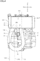
- FIG. 4 and FIG. 5 are front views of the engine 3, wherein the radiator and the exhaust pipe 10 are omitted in FIG. 5 .
- the engine 3 includes a crankcase 31, a cylinder body 32 connected to the crankcase 31, a cylinder head 33 connected to the cylinder body 32, and a cylinder head cover 34 connected to the cylinder head 33.
- a crankshaft (not shown) is arranged inside the crankcase 31.
- the crankcase 31 rotatably supports the crankshaft.
- the cylinder body 32 extends upward from the crankcase 31. Strictly speaking, the cylinder body 32 extends upward and forward from the crankcase 31.
- a cylinder (not shown) is arranged inside the cylinder body 32.
- a piston (not shown) is arranged inside the cylinder.
- the intake pipe and the exhaust pipe 10 are connected to the cylinder head 33.
- the engine 3 is a water-cooled internal combustion engine.
- FIG. 6 is a configuration diagram of a coolant circuit. As shown in FIG. 6 , a coolant passage 3W through which the coolant flows is formed inside the engine 3.
- the coolant passage 3W includes a first coolant passage 110 having a first inlet port 110i and a first outlet port 110o, and a second coolant passage 120 having a second inlet port 120i and a second outlet port 120o.
- the first coolant passage 110 includes a passage 110A formed inside the crankcase 31, a passage 110B formed inside the cylinder body 32, and a passage 110C formed inside the cylinder head 33.
- the second coolant passage 120 is formed inside the crankcase 31.
- the water pump 20 is attached to the side wall of the crankcase 31.
- the water pump 20 is attached to a right wall 31a of the crankcase 31.
- the water pump 20 has an inlet 20i for taking in the coolant, and an outlet 20o for discharging the coolant.
- the inlet 20i and the outlet 20o are connected directly to the coolant passage 3W of the engine 3.
- the inlet 20i of the water pump 20 is connected directly to the second outlet port 120o of the second coolant passage 120.
- the outlet 20o of the water pump 20 is connected directly to the first inlet port 110i of the first coolant passage 110.
- the radiator 40 is arranged forward relative to the engine 3. Specifically, the radiator 40 is arranged forward relative to the crankcase 31. The radiator 40 is arranged forward relative to the cylinder body 32. The radiator 40 is arranged forward relative to the cylinder head 33. The radiator 40 is arranged forward relative to the cylinder head cover 34. As shown in FIG. 4 , the radiator 40 includes a core portion 40A, a left tank 40LT provided in a left-side portion of the core portion 40A, and a right tank 40RT provided in a right-side portion of the core portion 40A. The left tank 40LT is formed with an inlet port 40i for the coolant (see FIG. 6 ). The right tank 40RT is formed with an outlet port 40o for the coolant. The coolant flows inside the core portion 40A, and the air flows outside the core portion 40A. The core portion 40A is configured to exchange heat between the coolant and the air.
- FIG. 8 represents a state where the thermostat 50 is removed from the crankcase 31.
- the crankcase 31 has a support surface 60s facing upward that supports the thermostat 50.
- the term "upward” as used herein is not limited to the upward direction along the vertical direction, and includes any direction that is inclined by an angle less than or equal to 45 degrees from the vertical direction.
- the support surface 60s includes a first support surface 61s that is formed with a first hole 61h, and a second support surface 62s that is formed with a second hole 62h.
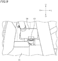
- FIG. 9 represents the thermostat 50 attached to the crankcase 31. A portion of the thermostat 50 is inserted in the first hole 61h. A bolt 63 for securing the thermostat 50 to the crankcase 31 is inserted through the second hole 62h.
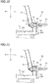
- the thermostat 50 is a so-called bottom-bypass-type thermostat. As shown in FIG. 10 , the thermostat 50 includes a case 55 and a valve 56 that is arranged inside the case 55.
- the case 55 is formed with a first inlet 51, a second inlet 52 and an outlet 53.
- the case 55 is formed in a tubular shape extending left and right. Although there is no particular limitation on the material of the case 55, the case 55 is made of a resin in the present embodiment.
- the valve 56 is movable leftward and rightward. In other words, the valve 56 is movable in the axial direction of the case 55.
- the left wall of the case 55 corresponds to the bottom wall.
- the first inlet 51 is formed on a right portion of the case 55. The first inlet 51 is open upward.
- the second inlet 52 is formed on the left wall of the case 55.
- the second inlet 52 is open sideward, and is herein open leftward.
- the outlet 53 is formed on a lower portion of the case 55. The outlet 53 is open downward.
- the thermostat 50 is configured to open the second inlet 52 when the temperature is less than the first temperature (see FIG. 11 ) and close the second inlet 52 when the temperature is greater than or equal to the first temperature (see FIG. 10 ).
- the thermostat 50 is configured to close the first inlet 51 when the temperature is less than or equal to the second temperature, which is lower than the first temperature (see FIG. 11 ).
- the first outlet port 110o of the first coolant passage 110 of the engine 3 and the inlet 40i of the radiator 40 are connected together by a first passageway 71.
- the outlet 40o of the radiator 40 and the first inlet 51 of the thermostat 50 are connected together by a second passageway 72.
- the first outlet port 110o of the first coolant passage 110 of the engine 3 and the second inlet 52 of the thermostat 50 are connected together by a bypass passageway 73.
- the outlet 53 of the thermostat 50 and the second inlet port 120i of the second coolant passage 120 of the engine 3 are directly connected together.
- the exhaust pipe 10 includes a first portion 11 extending forward from the cylinder head 33, a second portion 12 extending downward from the first portion 11, a third portion 13 (see FIG. 4 ) extending rightward from the second portion 12, a fourth portion 14 extending upward from the third portion 13, and a fifth portion 15 extending rearward from the fourth portion 14.
- the crankcase 31 has a crankcase cover 31S including the right wall 31a (see FIG. 2 and FIG. 5 ).
- FIG. 7 represents the shape of the water pump 20 as the vehicle is seen from the side.
- the water pump 20 includes a pump housing 20H attached to the crankcase cover 31S, and the pump cover 20C attached to the pump housing 20H.
- the water pump 20 includes an impeller that is rotatably supported on the crankcase cover 31S. The impeller is accommodated inside the pump housing 20H and arranged leftward of the pump cover 20C.
- the crankcase cover 31S, the pump housing 20H and the pump cover 20C together define the water passage of the water pump 20.
- the water pump 20 refers to a collection of parts for carrying the coolant, i.e., those parts that are attached to the crankcase cover 31S, such as the impeller, the pump housing 20H and the pump cover 20C, not including the crankcase cover 31S itself.
- Reference signs 20U, 20D, 20F and 20Re denote the upper end, the lower end, the front end and the rear end, respectively, of the water pump 20.
- the straight line 20FL represents a vertical line that passes through the front end 20F of the water pump 20.
- the straight line 20ReL represents a vertical line that passes through the rear end 20Re of the water pump 20.
- the straight line 20UL represents a horizontal line that passes through the upper end 20U of the water pump 20.
- the straight line 20DL represents a horizontal line that passes through the lower end 20D of the water pump 20.
- the fifth portion 15 of the exhaust pipe 10 includes an exhaust pipe portion 19 that is located between the front end 20F and the rear end 20Re of the water pump 20 and has an upper edge 19u located upward relative to the lower end 20D of the water pump 20.
- a lower edge 19d of the exhaust pipe portion 19 is located upward relative to the upper end 20U of the water pump 20.
- the exhaust pipe portion 19 overlaps with the cylinder body 32.
- the straight line 19AL represents a vertical line that passes through the outer end 19A of the exhaust pipe portion 19 in the vehicle width direction.
- the straight line 19BL represents a vertical line that passes through the inner end 19B of the exhaust pipe portion 19 in the vehicle width direction.
- the outward direction in the vehicle width direction refers to the direction away from the vehicle center line CL
- the inward direction in the vehicle width direction refers to the direction toward the vehicle center line CL.
- the thermostat 50 is arranged inward of the exhaust pipe portion 19 in the vehicle width direction.
- the straight line 20AL represents a vertical line that passes through the outer end 20A of the water pump 20 in the vehicle width direction.
- the straight line 20BL represents a vertical line that passes through the inner end 20B of the water pump 20 in the vehicle width direction.
- the inner end 19B of the exhaust pipe portion 19 in the vehicle width direction is located inward in the vehicle width direction relative to the outer end 20A of the water pump 20 in the vehicle width direction.
- the outer end 19A of the exhaust pipe portion 19 in the vehicle width direction is located outward in the vehicle width direction relative to the inner end 20B of the water pump 20 in the vehicle width direction.
- the water pump 20, the exhaust pipe portion 19 and the thermostat 50 are arranged rightward relative to the vehicle center line CL.
- the second passageway 72 is arranged rightward relative to the vehicle center line CL.
- At least a portion of the first passageway 71 and at least a portion of the bypass passageway 73 are arranged leftward relative to the vehicle center line CL.
- the exhaust pipe portion 19 includes a portion that overlaps with the cylinder body 32 as the vehicle is seen from the side.
- the second passageway 72 does not overlap with the cylinder body 32, the cylinder head 33 and the cylinder head cover 34 as the vehicle is seen from the side.
- the first passageway 71 includes a portion that overlaps with the cylinder head cover 34 as the vehicle is seen from the side.
- the bypass passageway 73 includes a portion that overlaps with the cylinder body 32 as the vehicle is seen from the side.
- the motorcycle 1 is configured as described above. Next, the circulation of the coolant will be described.
- the temperature of the engine 3 is relatively low. Therefore, the temperature of the thermostat 50 is relatively low.
- the valve 56 opens the second inlet 52 as shown in FIG. 11 .
- the coolant flows through the water pump 20, the first coolant passage 110, the bypass passageway 73, the thermostat 50 and the second coolant passage 120 in this order. Since the coolant is not cooled in the radiator 40, the temperature of the coolant flowing through the first coolant passage 110 and the second coolant passage 120 is relatively high. Therefore, the engine 3 is warmed quickly.
- the temperature of the thermostat 50 becomes greater than or equal to the first temperature. Then, as shown in FIG. 10 , the valve 56 closes the second inlet 52. As a result, as indicated by a solid-line arrow in FIG. 6 , the coolant flows through the water pump 20, the first coolant passage 110, the first passageway 71, the radiator 40, the second passageway 72, the thermostat 50 and the second coolant passage 120 in this order. Since the coolant is cooled in the radiator 40, the temperature of the coolant flowing through the first coolant passage 110 and the second coolant passage 120 is relatively low. Therefore, the engine 3 is cooled sufficiently.
- the inlet 20i and the outlet 20o of the water pump 20 are connected directly to the coolant passage 3W of the engine 3.
- the upper edge 19u of the exhaust pipe portion 19 is located upward relative to the lower end 20D of the water pump 20. Since the exhaust pipe 10 is arranged at a relatively high position, it is possible to ensure a sufficient minimum ground clearance. Since there is no overlap between the exhaust pipe portion 19 and the water pump 20 in the vehicle width direction, it is possible to reduce the size of the motorcycle 1 in the vehicle width direction.
- the thermostat 50 is arranged forward of the cylinder body 32.
- the dead space forward of the cylinder body 32 can be effectively used as a space for installment of the thermostat 50.
- the thermostat 50 is located inward in the vehicle width direction relative to the exhaust pipe portion 19.
- the thermostat 50 does not protrude outward in the vehicle width direction relative to the exhaust pipe portion 19. This also reduces the size of the motorcycle 1 in the vehicle width direction.
- the advantageous effects described above are organically combined together, making it possible to ensure a sufficient minimum ground clearance while reducing the size in the vehicle width direction.
- the lower edge 19d of the exhaust pipe portion 19 is located upward relative to the upper end 20U of the water pump 20.
- the inner end 19B of the exhaust pipe portion 19 in the vehicle width direction is located inward in the vehicle width direction relative to the outer end 20A of the water pump 20 in the vehicle width direction
- the outer end 19A of the exhaust pipe portion 19 in the vehicle width direction is located outward in the vehicle width direction relative to the inner end 20B of the water pump 20 in the vehicle width direction.
- at least a portion of the exhaust pipe portion 19 is arranged at the same position as the water pump 20.
- the exhaust pipe portion 19 less protrudes outward in the vehicle width direction. Therefore, it is possible to further reduce the size of the motorcycle 1 in the vehicle width direction.
- the exhaust pipe portion 19 overlaps with the cylinder body 32 as the vehicle is seen from the side.
- at least a portion of the exhaust pipe portion 19 is arranged at the same position as the cylinder body 32.
- the exhaust pipe portion 19 less protrudes upward.
- the thermostat 50 is attached to the crankcase 31. Since the cylinder body 32 and the cylinder head 33 do not have an attachment portion for the attachment of the thermostat 50, it is possible to prevent an increase in size of the cylinder body 32 and the cylinder head 33. It is possible to ensure a relatively large space, on the crankcase 31, as a space for attachment of the thermostat 50. According to the present embodiment, since the thermostat 50 is attached to the crankcase 31, it is easy to provide a large thermostat 50. The provision of a large thermostat 50 increases the flow rate of the coolant.
- the thermostat 50 is supported on the support surface 60s (see FIG. 8 ) facing upward of the crankcase 31. Therefore, even when the engine 3 vibrates in the up-down direction, the thermostat 50 is stably supported on the crankcase 31.
- the support surface 60s includes the first support surface 61s, which has the first hole 61h in which a portion of the thermostat 50 is inserted, and the second support surface 62s, which has the second hole 62h through which the bolt 63 (see FIG. 9 ) for securing the thermostat 50 to the crankcase 31 is inserted.
- the thermostat 50 is secured to the crankcase 31 by the bolt 63 extending downward.
- the second hole 62h, through which the bolt 63 is inserted is formed forward of the first support surface 61s. As compared with a case where the second hole 62h is formed leftward or rightward of the first support surface 61s, it is possible to reduce the size of the thermostat 50 in the vehicle width direction.
- the thermostat 50 is arranged forward of the cylinder body 32 (see FIG. 3 ). A relatively large space is ensured as a space for installment of the thermostat 50. Thus, the bottom-bypass-type thermostat 50 can be arranged without difficulty.
- the first inlet 51 of the case 55 of the thermostat 50 is open upward, the second inlet 52 is open sideward, and the outlet 53 is open downward. Therefore, it is possible to easily avoid interference between the second passageway 72 connected to the first inlet 51, the bypass passageway 73 connected to the second inlet 52, and the coolant passageway (the second coolant passage 120) connected to the outlet.
- the thermostat 50 is installed in the horizontal direction. That is, the thermostat 50 is installed so that the axis of the case 55 extends in the vehicle width direction, and the valve 56 of the thermostat 50 is movable leftward and rightward (see FIG. 10 and FIG. 11 ). As described above, according to the present embodiment, it is possible to ensure a relatively large space as a space for installment of the thermostat 50, and the bottom-bypass-type thermostat 50 whose valve 56 moves leftward and rightward can be arranged without difficulty.
- the water pump 20, the exhaust pipe portion 19, the thermostat 50 and the second passageway 72 are arranged rightward relative to the vehicle center line CL. At least a portion of the first passageway 71 and at least a portion of the bypass passageway 73 are arranged leftward relative to the vehicle center line CL.
- the first passageway 71, the second passageway 72 and the bypass passageway 73 are coolant passageways arranged outside the engine 3 (hereinafter referred to as external coolant passageways).
- the external coolant passageways are arranged separately on the left and right side of the vehicle center line CL, they are unlikely to interfere with each other.
- the external coolant passageways are arranged in a compact arrangement. Therefore, it is possible to reduce the size of the motorcycle 1 in the vehicle width direction.
- the exhaust pipe portion 19 includes a portion that overlaps with the cylinder body 32 as the vehicle is seen from the side.
- the first passageway 71 includes a portion that overlaps with the cylinder head cover 34 as the vehicle is seen from the side.
- the bypass passageway 73 includes a portion that overlaps with the cylinder body 32 as the vehicle is seen from the side.
- the exhaust pipe portion 19, the first passageway 71 and the bypass passageway 73 are arranged in a compact arrangement while avoiding interference therebetween.
- the lower edge 19d of the exhaust pipe portion 19 may be located downward relative to the upper end 20U of the water pump 20. As the vehicle is seen from the side, at least a portion of the exhaust pipe portion 19 and the water pump 20 may overlap with each other.
- the exhaust pipe portion 19 and the water pump 20 may be arranged at different positions.
- the exhaust pipe portion 19 may be arranged leftward relative to the water pump 20.
- the exhaust pipe portion 19 does not need to overlap with the cylinder body 32.
- the support surface 60s that supports the thermostat 50 does not always need to be facing upward.
- the support surface 60s may be facing forward or sideward.
- the second support surface 62s does not always need to be formed forward of the first support surface 61s.
- the second support surface 62s may be formed sideward of the first support surface 61s.
- the thermostat 50 may be attached to a part other than the crankcase 31 of the engine 3.
- the thermostat 50 may be attached to the cylinder body 32.
- the orientations of the first inlet 51, the second inlet 52 and the outlet 53 of the thermostat 50 may be different from those of the embodiment described above.
- the direction of movement of the valve 56 of the thermostat 50 is not limited to leftward and rightward.
- the thermostat 50 may be arranged so that the valve 56 moves upward and downward.
- a thermostat of a type other than a bottom-bypass type may be used as the thermostat 50.
- the water pump 20, the exhaust pipe 10, the thermostat 50, the first passageway 71, the second passageway 72, the bypass passageway 73 and the radiator 40 may be arranged in positions that are left-right-inverted from those of the embodiment described above.
- the water pump 20, the exhaust pipe portion 19, the thermostat 50 and the second passageway 72 may be arranged leftward relative to the vehicle center line CL, and at least a portion of the first passageway 71 and at least a portion of the bypass passageway 73 may be arranged rightward relative to the vehicle center line CL.
- the exhaust pipe portion 19 does not always need to include a portion that overlaps with the cylinder body 32 as the vehicle is seen from the side.
- the first passageway 71 does not always need to include a portion that overlaps with the cylinder head cover 34 as the vehicle is seen from the side.
- the bypass passageway 73 does not always need to include a portion that overlaps with the cylinder body 32 as the vehicle is seen from the side.
- a straddled vehicle refers to a vehicle that is straddled by a passenger.
- the straddled vehicle is not limited to the motorcycle 1.
- the straddled vehicle may be an auto tricycle, an ATV (All Terrain Vehicle), or a snowmobile, for example.
Landscapes
- Engineering & Computer Science (AREA)
- Mechanical Engineering (AREA)
- Chemical & Material Sciences (AREA)
- Combustion & Propulsion (AREA)
- General Engineering & Computer Science (AREA)
- Cylinder Crankcases Of Internal Combustion Engines (AREA)
Abstract
Description
- The present invention relates to a straddled vehicle having a water-cooled internal combustion engine.
- Straddled vehicles having water-cooled internal combustion engines have been known in the art. For example,
JP 2017-82647 A - When the temperature of the coolant is low, e.g., at start-up of the engine, the thermostat opens the bypass passage. The coolant discharged from the water pump flows through the inside of the engine, the first passage, the bypass passage and the second passage in this order before returning to the water pump. In this case, the coolant does not pass through the radiator and is not cooled therethrough. The coolant of a relatively high temperature flows through the engine. Therefore, the engine is warmed quickly.
- When the engine is warmed, the temperature of the coolant increases, and the thermostat closes the bypass passage. The coolant discharged from the water pump flows through the inside of the engine, the first passage, the radiator and the second passage in this order before returning to the water pump. In this case, the coolant is cooled through the radiator. The coolant of a relatively low temperature flows through the engine. Therefore, the engine is cooled sufficiently.
- With the motorcycle disclosed in
JP 2017-82647 A - Now, when a straddled vehicle runs off road, the straddled vehicle preferably has a high minimum ground clearance. With a straddled vehicle whose vehicle body is leaned when turning left and when turning right, the minimum ground clearance is preferably high in order to ensure a sufficient maximum bank angle. Note that the minimum ground clearance refers to the height, from the ground, of the lowest part of the straddled vehicle excluding the wheels.
- For example, with the motorcycle disclosed in
JP 2017-82647 A - The water pump, which is arranged sideward of the engine due to functional limitations, and the radiator are connected by a hose. If the above-mentioned portion of the exhaust pipe is arranged at a relatively high position, the hose and the above-mentioned portion of the exhaust pipe may possibly interfere with each other. In order to avoid such interference, one may consider arranging the above-mentioned portion of the exhaust pipe sideward of the hose. This however increases the size of the straddled vehicle in the vehicle width direction.
- An object of the present invention is to provide a straddled vehicle that includes a water-cooled internal combustion engine having a coolant bypass passage and that can ensure a sufficient minimum ground clearance while reducing the size in the vehicle width direction. According to the present invention said object is solved by a straddled vehicle having the features of
independent claim 1. Preferred embodiments are laid down in the dependent claims. - A straddled vehicle disclosed herein includes an internal combustion engine including a crankcase having a side wall, a cylinder body connected to the crankcase, and a cylinder head connected to the cylinder body. The straddled vehicle includes: a water pump attached to the side wall of the crankcase; a radiator arranged forward relative to the cylinder body; a thermostat arranged forward of the cylinder body and rearward relative to the radiator; and an exhaust pipe that is connected to the cylinder head and through which an exhaust gas passes. A coolant passage through which a coolant flows is formed inside the internal combustion engine. The water pump includes an inlet and an outlet connected directly to the coolant passage. The exhaust pipe includes an exhaust pipe portion that is located between a front end and a rear end of the water pump and that has an upper edge located upward relative to a lower end of the water pump as the vehicle is seen from the side. The thermostat is arranged inward relative to the exhaust pipe portion in a vehicle width direction.
- With the straddled vehicle described above, the inlet and the outlet of the water pump are connected directly to the coolant passage of the internal combustion engine. There is no member, such as a hose, for connecting together the water pump and the radiator. Therefore, no interference will occur between a member, such as a hose, for connecting together the water pump and the radiator and a portion of the exhaust pipe (i.e., the exhaust pipe portion). Thus, it is possible to reduce the size of the straddled vehicle in the vehicle width direction.
- With the straddled vehicle described above, the upper edge of the exhaust pipe portion is located upward relative to the lower end of the water pump. Since the exhaust pipe is arranged at a relatively high position, it is possible to ensure a sufficient minimum ground clearance. Since there is little or no overlap between the exhaust pipe portion and the water pump in the vehicle width direction, it is possible to reduce the size of the straddled vehicle in the vehicle width direction.
- With the straddled vehicle described above, the thermostat is arranged forward of the cylinder body. The dead space forward of the cylinder body can be effectively used as a space for installment of the thermostat.
- With the straddled vehicle described above, the thermostat is located inward in the vehicle width direction relative to the exhaust pipe portion. The thermostat does not protrude outward in the vehicle width direction relative to the exhaust pipe portion. This also reduces the size of the straddled vehicle in the vehicle width direction.
- Thus, with the straddled vehicle described above, it is possible to ensure a sufficient minimum ground clearance while reducing the size in the vehicle width direction.
- According to a preferred embodiment, a lower edge of the exhaust pipe portion is located upward relative to an upper end of the water pump.
- According to the embodiment described above, it is possible to ensure a sufficient minimum ground clearance of the straddled vehicle.
- According to a preferred embodiment, an inner end of the exhaust pipe portion in the vehicle width direction is located inward in the vehicle width direction relative to an outer end of the water pump in the vehicle width direction. An outer end of the exhaust pipe portion in the vehicle width direction is located outward in the vehicle width direction relative to an inner end of the water pump in the vehicle width direction.
- According to the embodiment described above, for the vehicle width direction, at least a portion of the exhaust pipe portion is arranged at the same position as the water pump. As compared with a case where the entirety of the exhaust pipe portion is arranged outward in the vehicle width direction relative to the water pump, the exhaust pipe portion less protrudes outward in the vehicle width direction. Therefore, it is possible to further reduce the size of the straddled vehicle in the vehicle width direction.
- According to a preferred embodiment, at least a portion of the exhaust pipe portion overlaps with the cylinder body as the vehicle is seen from the side.
- According to the embodiment described above, for the up-down direction, at least a portion of the exhaust pipe portion is arranged at the same position as the cylinder body. As compared with a case where the entirety of the exhaust pipe portion is arranged upward relative to the cylinder body, the exhaust pipe portion less protrudes upward.
- According to a preferred embodiment, the thermostat is attached to the crankcase.
- According to the embodiment described above, since the cylinder body and the cylinder head do not have an attachment portion for the attachment of the thermostat, it is possible to prevent an increase in size of the cylinder body and the cylinder head. It is possible to ensure a relatively large space, on the crankcase, as a space for attachment of the thermostat. Therefore, it is easy to provide a large thermostat. The provision of a large thermostat reduces the water flow resistance.
- According to a preferred embodiment, the crankcase has a support surface facing upward. The thermostat is supported on the support surface.
- While the straddled vehicle is running, the internal combustion engine is subject to vibrations in the up-down direction. According to the embodiment described above, even when the internal combustion engine vibrates in the up-down direction, the thermostat is stably supported on the crankcase.
- According to a preferred embodiment, the support surface includes a first support surface that is formed with a first hole and a second support surface that is formed with a second hole and formed forward of the first support surface. A portion of the thermostat is inserted in the first hole. A bolt for securing the thermostat to the crankcase is inserted through the second hole.
- According to the embodiment described above, the thermostat is secured to the crankcase by the bolt extending downward. Thus, even when the internal combustion engine vibrates in the up-down direction, the thermostat is more stably supported on the crankcase. According to the embodiment described above, the second hole, through which the bolt is inserted, is formed forward of the first support surface. As compared with a case where the second hole is formed sideward of the first support surface, it is possible to reduce the size of the thermostat in the vehicle width direction.
- According to a preferred embodiment, the thermostat is a bottom-bypass-type thermostat that includes a case formed with a first inlet, a second inlet and an outlet, and a valve arranged in the case, wherein the valve opens the second inlet when temperature is less than a first temperature and closes the second inlet when temperature is greater than or equal to the first temperature.
- With the straddled vehicle described above, the thermostat is arranged forward of the cylinder body. Since a relatively large space is ensured as a space for installment of the thermostat, the bottom-bypass-type thermostat can be arranged without difficulty.
- According to a preferred embodiment, the first inlet is open upward, the second inlet is open sideward, and the outlet is open downward.
- According to the embodiment described above, it is possible to avoid interference between the coolant passageway connected to the first inlet of the thermostat, the coolant passageway connected to the second inlet, and the coolant passageway connected to the outlet.
- According to a preferred embodiment, the valve of the thermostat is configured to be movable leftward and rightward.
- As described above, with the straddled vehicle described above, it is possible to ensure a relatively large space as a space for installment of the thermostat, and the bottom-bypass-type thermostat whose valve moves leftward and rightward can be arranged without difficulty.
- According to a preferred embodiment, the coolant passage of the internal combustion engine includes a first coolant passage having a first inlet port and a first outlet port, and a second coolant passage having a second inlet port and a second outlet port. The inlet of the water pump is connected to the second outlet port of the second coolant passage, and the outlet of the water pump is connected to the first inlet port of the first coolant passage. The radiator has an inlet and an outlet. The straddled vehicle includes: a first passageway connected to the first outlet port of the first coolant passage and the inlet of the radiator; a second passageway connected to the outlet of the radiator and the first inlet of the thermostat; and a bypass passageway connected to the first outlet port of the first coolant passage and the second inlet of the thermostat. The outlet of the thermostat is connected to the second inlet port of the second coolant passage.
- According to the embodiment described above, when the temperature of the coolant in the thermostat is less than the first temperature, the coolant flows through the water pump, the first coolant passage, the bypass passageway, the thermostat and the second coolant passage in this order. Since the coolant is not cooled in the radiator, the temperature of the coolant flowing through the first coolant passage and the second coolant passage is relatively high. Therefore, the internal combustion engine is warmed quickly. On the other hand, when the temperature of the internal combustion engine becomes high, the temperature of the coolant in the thermostat becomes greater than or equal to the first temperature. Then, the coolant flows through the water pump, the first coolant passage, the first passageway, the radiator, the second passageway, the thermostat and the second coolant passage in this order. Since the coolant is cooled in the radiator, the temperature of the coolant flowing through the first coolant passage and the second coolant passage is relatively low. Therefore, the internal combustion engine is cooled.
- According to a preferred embodiment, the water pump, the exhaust pipe portion, the thermostat and the second passageway are arranged rightward relative to a vehicle center line, and at least a portion of the first passageway and at least a portion of the bypass passageway are arranged leftward relative to the vehicle center line. According to a preferred embodiment, the water pump, the exhaust pipe portion, the thermostat and the second passageway are arranged leftward relative to the vehicle center line, and at least a portion of the first passageway and at least a portion of the bypass passageway are arranged rightward relative to the vehicle center line.
- The first passageway, the second passageway and the bypass passageway are coolant passageways arranged outside the internal combustion engine (hereinafter referred to as external coolant passageways). According to the embodiment described above, since a portion of the external coolant passageways is arranged rightward of the vehicle center line and another portion thereof is arranged leftward of the vehicle center line. Since the external coolant passageways are arranged separately on the left and right side of the vehicle center line, they are unlikely to interfere with each other. The external coolant passageways are arranged in a compact arrangement. Therefore, it is possible to reduce the size of the straddled vehicle in the vehicle width direction.
- According to a preferred embodiment, the internal combustion engine includes a cylinder head cover connected to the cylinder head. The exhaust pipe portion includes a portion that overlaps with the cylinder body as the vehicle is seen from the side. The first passageway includes a portion that overlaps with the cylinder head cover as the vehicle is seen from the side. The bypass passageway includes a portion that overlaps with the cylinder body as the vehicle is seen from the side.
- According to the embodiment described above, the exhaust pipe portion, the first passageway and the bypass passageway are arranged in a compact arrangement while avoiding interference therebetween.
- According to the present invention, it is possible to provide a straddled vehicle that includes a water-cooled internal combustion engine having a coolant bypass passage and that ensures a sufficient minimum ground clearance while reducing the size in the vehicle width direction.
-
-
FIG. 1 is a right side view of a motorcycle according to an embodiment. -
FIG. 2 is a right side view of an internal combustion engine, etc. -
FIG. 3 is a left side view of the internal combustion engine, etc. -
FIG. 4 is a front view of the internal combustion engine, etc. -
FIG. 5 is a view similar toFIG. 4 , wherein a radiator and an exhaust pipe are omitted. -
FIG. 6 is a configuration diagram of a coolant circuit. -
FIG. 7 is a view showing a shape of a water pump as the vehicle is seen from the side. -
FIG. 8 is a front view showing, on an enlarged scale, a portion of the internal combustion engine with a thermostat not attached thereto. -
FIG. 9 is a front view showing, on an enlarged scale, a portion of the internal combustion engine with the thermostat attached thereto. -
FIG. 10 is a cross-sectional view of the thermostat where the first inlet is open and the second inlet is closed. -
FIG. 11 is a cross-sectional view of the thermostat where the first inlet is closed and the second inlet is open. - One embodiment will now be described with reference to the drawings.
FIG. 1 is a right side view of amotorcycle 1, which is an example of a straddled vehicle. Themotorcycle 1 includes a vehicle body frame 2, an internal combustion engine (hereinafter referred to as an engine) 3 supported on the vehicle body frame 2, arear wheel 4 driven by theengine 3, a front wheel 5, afuel tank 6, and aseat 7 on which the passenger sits. Themotorcycle 1 includes an intake pipe (not shown) connected to theengine 3, anexhaust pipe 10 connected to theengine 3, awater pump 20, a radiator 40 (seeFIG. 2 ), and a thermostat 50 (seeFIG. 3 ). - The terms front, rear, left, right, up and down, as used in the description below, refer to these directions as seen from a virtual passenger seated on the
seat 7 while themotorcycle 1 is standing upright on a horizontal surface with no passenger and no load thereon, unless specified otherwise. The designations F, Re, L, R, U and D, as used in the figures, refer to front, rear, left, right, up and down, respectively. The term "front/forward" refers not only to the direction that extends in the front direction along the vehicle center line, as the vehicle is seen from above, but also to directions that are inclined left/right from that direction by an angle that is less than or equal to 45 degrees. Similarly, the term "rear/rearward" refers not only to the direction that extends rearward along the vehicle center line, as the vehicle is seen from above, but also to directions that are inclined left/right from that direction by an angle of 45 degrees of less. The term "left/leftward" refers not only to the direction that extends leftward vertical to the vehicle center line, as the vehicle is seen from above, but also to directions that are inclined frontward/rearward from that direction by an angle of 45 degrees of less. The term "right/rightward" refers not only to the direction that extends rightward vertical to the vehicle center line, as the vehicle is seen from above, but also to directions that are inclined frontward/rearward from that direction by an angle of 45 degrees of less. The term "up/upward" refers not only to the vertically upward direction, as the vehicle is seen from the side, but also to directions that are inclined frontward/rearward from that direction by an angle of 45 degrees of less. The term "down/downward" refers not only to the vertically downward direction, as the vehicle is seen from the side, but also to directions that are inclined frontward/rearward from that direction by an angle of 45 degrees of less. -
FIG. 2 is a right side view of theengine 3.FIG. 3 is a left side view of theengine 3.FIG. 4 andFIG. 5 are front views of theengine 3, wherein the radiator and theexhaust pipe 10 are omitted inFIG. 5 . Theengine 3 includes acrankcase 31, acylinder body 32 connected to thecrankcase 31, acylinder head 33 connected to thecylinder body 32, and acylinder head cover 34 connected to thecylinder head 33. A crankshaft (not shown) is arranged inside thecrankcase 31. Thecrankcase 31 rotatably supports the crankshaft. Thecylinder body 32 extends upward from thecrankcase 31. Strictly speaking, thecylinder body 32 extends upward and forward from thecrankcase 31. A cylinder (not shown) is arranged inside thecylinder body 32. A piston (not shown) is arranged inside the cylinder. The intake pipe and theexhaust pipe 10 are connected to thecylinder head 33. - The
engine 3 is a water-cooled internal combustion engine.FIG. 6 is a configuration diagram of a coolant circuit. As shown inFIG. 6 , acoolant passage 3W through which the coolant flows is formed inside theengine 3. Thecoolant passage 3W includes afirst coolant passage 110 having a first inlet port 110i and a first outlet port 110o, and asecond coolant passage 120 having asecond inlet port 120i and a second outlet port 120o. Herein, thefirst coolant passage 110 includes apassage 110A formed inside thecrankcase 31, apassage 110B formed inside thecylinder body 32, and apassage 110C formed inside thecylinder head 33. Thesecond coolant passage 120 is formed inside thecrankcase 31. - The
water pump 20 is attached to the side wall of thecrankcase 31. Herein, thewater pump 20 is attached to aright wall 31a of thecrankcase 31. As shown inFIG. 6 , thewater pump 20 has an inlet 20i for taking in the coolant, and an outlet 20o for discharging the coolant. The inlet 20i and the outlet 20o are connected directly to thecoolant passage 3W of theengine 3. Herein, the inlet 20i of thewater pump 20 is connected directly to the second outlet port 120o of thesecond coolant passage 120. The outlet 20o of thewater pump 20 is connected directly to the first inlet port 110i of thefirst coolant passage 110. - As shown in
FIG. 2 , theradiator 40 is arranged forward relative to theengine 3. Specifically, theradiator 40 is arranged forward relative to thecrankcase 31. Theradiator 40 is arranged forward relative to thecylinder body 32. Theradiator 40 is arranged forward relative to thecylinder head 33. Theradiator 40 is arranged forward relative to thecylinder head cover 34. As shown inFIG. 4 , theradiator 40 includes acore portion 40A, a left tank 40LT provided in a left-side portion of thecore portion 40A, and a right tank 40RT provided in a right-side portion of thecore portion 40A. The left tank 40LT is formed with aninlet port 40i for the coolant (seeFIG. 6 ). The right tank 40RT is formed with an outlet port 40o for the coolant. The coolant flows inside thecore portion 40A, and the air flows outside thecore portion 40A. Thecore portion 40A is configured to exchange heat between the coolant and the air. - As shown in
FIG. 3 , thethermostat 50 is arranged forward of thecylinder body 32 and rearward relative to theradiator 40. Thethermostat 50 is attached to thecrankcase 31.FIG. 8 represents a state where thethermostat 50 is removed from thecrankcase 31. As shown inFIG. 8 , thecrankcase 31 has asupport surface 60s facing upward that supports thethermostat 50. Note that the term "upward" as used herein is not limited to the upward direction along the vertical direction, and includes any direction that is inclined by an angle less than or equal to 45 degrees from the vertical direction. Thesupport surface 60s includes afirst support surface 61s that is formed with afirst hole 61h, and asecond support surface 62s that is formed with asecond hole 62h. Thefirst hole 61h and thesecond hole 62h are open upward. Thesecond hole 62h is formed forward of thefirst hole 61h. Thesecond support surface 62s is arranged forward of thefirst support surface 61s.FIG. 9 represents thethermostat 50 attached to thecrankcase 31. A portion of thethermostat 50 is inserted in thefirst hole 61h. Abolt 63 for securing thethermostat 50 to thecrankcase 31 is inserted through thesecond hole 62h. - The
thermostat 50 is a so-called bottom-bypass-type thermostat. As shown inFIG. 10 , thethermostat 50 includes acase 55 and avalve 56 that is arranged inside thecase 55. Thecase 55 is formed with afirst inlet 51, asecond inlet 52 and anoutlet 53. Thecase 55 is formed in a tubular shape extending left and right. Although there is no particular limitation on the material of thecase 55, thecase 55 is made of a resin in the present embodiment. Thevalve 56 is movable leftward and rightward. In other words, thevalve 56 is movable in the axial direction of thecase 55. The left wall of thecase 55 corresponds to the bottom wall. Thefirst inlet 51 is formed on a right portion of thecase 55. Thefirst inlet 51 is open upward. Thesecond inlet 52 is formed on the left wall of thecase 55. Thesecond inlet 52 is open sideward, and is herein open leftward. Theoutlet 53 is formed on a lower portion of thecase 55. Theoutlet 53 is open downward. Thethermostat 50 is configured to open thesecond inlet 52 when the temperature is less than the first temperature (seeFIG. 11 ) and close thesecond inlet 52 when the temperature is greater than or equal to the first temperature (seeFIG. 10 ). Thethermostat 50 is configured to close thefirst inlet 51 when the temperature is less than or equal to the second temperature, which is lower than the first temperature (seeFIG. 11 ). - As shown in
FIG. 6 , the first outlet port 110o of thefirst coolant passage 110 of theengine 3 and theinlet 40i of theradiator 40 are connected together by afirst passageway 71. The outlet 40o of theradiator 40 and thefirst inlet 51 of thethermostat 50 are connected together by asecond passageway 72. The first outlet port 110o of thefirst coolant passage 110 of theengine 3 and thesecond inlet 52 of thethermostat 50 are connected together by abypass passageway 73. Theoutlet 53 of thethermostat 50 and thesecond inlet port 120i of thesecond coolant passage 120 of theengine 3 are directly connected together. There is no particular limitation on the material of thefirst passageway 71, thesecond passageway 72 and thebypass passageway 73. - As shown in
FIG. 2 , theexhaust pipe 10 includes afirst portion 11 extending forward from thecylinder head 33, asecond portion 12 extending downward from thefirst portion 11, a third portion 13 (seeFIG. 4 ) extending rightward from thesecond portion 12, afourth portion 14 extending upward from thethird portion 13, and afifth portion 15 extending rearward from thefourth portion 14. - The
crankcase 31 has acrankcase cover 31S including theright wall 31a (seeFIG. 2 andFIG. 5 ).FIG. 7 represents the shape of thewater pump 20 as the vehicle is seen from the side. In the present embodiment, thewater pump 20 includes apump housing 20H attached to thecrankcase cover 31S, and thepump cover 20C attached to thepump housing 20H. Although not shown in the figure, thewater pump 20 includes an impeller that is rotatably supported on thecrankcase cover 31S. The impeller is accommodated inside thepump housing 20H and arranged leftward of thepump cover 20C. Thecrankcase cover 31S, thepump housing 20H and thepump cover 20C together define the water passage of thewater pump 20. In the present embodiment, thewater pump 20 refers to a collection of parts for carrying the coolant, i.e., those parts that are attached to thecrankcase cover 31S, such as the impeller, thepump housing 20H and thepump cover 20C, not including thecrankcase cover 31S itself. Reference signs 20U, 20D, 20F and 20Re denote the upper end, the lower end, the front end and the rear end, respectively, of thewater pump 20. - In
FIG. 2 , the straight line 20FL represents a vertical line that passes through thefront end 20F of thewater pump 20. The straight line 20ReL represents a vertical line that passes through the rear end 20Re of thewater pump 20. The straight line 20UL represents a horizontal line that passes through theupper end 20U of thewater pump 20. The straight line 20DL represents a horizontal line that passes through thelower end 20D of thewater pump 20. As shown inFIG. 2 , as the vehicle is seen from the side, thefifth portion 15 of theexhaust pipe 10 includes anexhaust pipe portion 19 that is located between thefront end 20F and the rear end 20Re of thewater pump 20 and has anupper edge 19u located upward relative to thelower end 20D of thewater pump 20. Alower edge 19d of theexhaust pipe portion 19 is located upward relative to theupper end 20U of thewater pump 20. As the vehicle is seen from the side, theexhaust pipe portion 19 overlaps with thecylinder body 32. - In
FIG. 4 andFIG. 5 , the straight line 19AL represents a vertical line that passes through theouter end 19A of theexhaust pipe portion 19 in the vehicle width direction. The straight line 19BL represents a vertical line that passes through theinner end 19B of theexhaust pipe portion 19 in the vehicle width direction. Note that the outward direction in the vehicle width direction refers to the direction away from the vehicle center line CL, and the inward direction in the vehicle width direction refers to the direction toward the vehicle center line CL. As shown inFIG. 4 , as the vehicle is seen from the front side, thethermostat 50 is arranged inward of theexhaust pipe portion 19 in the vehicle width direction. - In
FIG. 5 , the straight line 20AL represents a vertical line that passes through theouter end 20A of thewater pump 20 in the vehicle width direction. The straight line 20BL represents a vertical line that passes through theinner end 20B of thewater pump 20 in the vehicle width direction. As shown inFIG. 5 , theinner end 19B of theexhaust pipe portion 19 in the vehicle width direction is located inward in the vehicle width direction relative to theouter end 20A of thewater pump 20 in the vehicle width direction. Theouter end 19A of theexhaust pipe portion 19 in the vehicle width direction is located outward in the vehicle width direction relative to theinner end 20B of thewater pump 20 in the vehicle width direction. - As shown in
FIG. 5 , thewater pump 20, theexhaust pipe portion 19 and thethermostat 50 are arranged rightward relative to the vehicle center line CL. As shown inFIG. 4 , thesecond passageway 72 is arranged rightward relative to the vehicle center line CL. At least a portion of thefirst passageway 71 and at least a portion of thebypass passageway 73 are arranged leftward relative to the vehicle center line CL. - As shown in
FIG. 2 , theexhaust pipe portion 19 includes a portion that overlaps with thecylinder body 32 as the vehicle is seen from the side. Thesecond passageway 72 does not overlap with thecylinder body 32, thecylinder head 33 and thecylinder head cover 34 as the vehicle is seen from the side. As shown inFIG. 3 , thefirst passageway 71 includes a portion that overlaps with thecylinder head cover 34 as the vehicle is seen from the side. Thebypass passageway 73 includes a portion that overlaps with thecylinder body 32 as the vehicle is seen from the side. - The
motorcycle 1 is configured as described above. Next, the circulation of the coolant will be described. - Immediately after start-up of the
engine 3 of themotorcycle 1, the temperature of theengine 3 is relatively low. Therefore, the temperature of thethermostat 50 is relatively low. When the temperature of thethermostat 50 is less than the first temperature, thevalve 56 opens thesecond inlet 52 as shown inFIG. 11 . As a result, as indicated by a broken-line arrow inFIG. 6 , the coolant flows through thewater pump 20, thefirst coolant passage 110, thebypass passageway 73, thethermostat 50 and thesecond coolant passage 120 in this order. Since the coolant is not cooled in theradiator 40, the temperature of the coolant flowing through thefirst coolant passage 110 and thesecond coolant passage 120 is relatively high. Therefore, theengine 3 is warmed quickly. - When the temperature of the
engine 3 becomes high, the temperature of thethermostat 50 becomes greater than or equal to the first temperature. Then, as shown inFIG. 10 , thevalve 56 closes thesecond inlet 52. As a result, as indicated by a solid-line arrow inFIG. 6 , the coolant flows through thewater pump 20, thefirst coolant passage 110, thefirst passageway 71, theradiator 40, thesecond passageway 72, thethermostat 50 and thesecond coolant passage 120 in this order. Since the coolant is cooled in theradiator 40, the temperature of the coolant flowing through thefirst coolant passage 110 and thesecond coolant passage 120 is relatively low. Therefore, theengine 3 is cooled sufficiently. - As described above, with the
motorcycle 1 according to the present embodiment, as shown inFIG. 6 , the inlet 20i and the outlet 20o of thewater pump 20 are connected directly to thecoolant passage 3W of theengine 3. There is no member such as a hose that connects together thewater pump 20 and the radiator 40 (seeFIG. 2 ). Therefore, there is no possibility that a member such as a hose that connects together thewater pump 20 and theradiator 40 interferes with a portion (i.e., the exhaust pipe portion) 19 of theexhaust pipe 10. This reduces the size of themotorcycle 1 in the vehicle width direction. - With the
motorcycle 1, as shown inFIG. 2 , theupper edge 19u of theexhaust pipe portion 19 is located upward relative to thelower end 20D of thewater pump 20. Since theexhaust pipe 10 is arranged at a relatively high position, it is possible to ensure a sufficient minimum ground clearance. Since there is no overlap between theexhaust pipe portion 19 and thewater pump 20 in the vehicle width direction, it is possible to reduce the size of themotorcycle 1 in the vehicle width direction. - With the
motorcycle 1, as shown inFIG. 3 , thethermostat 50 is arranged forward of thecylinder body 32. The dead space forward of thecylinder body 32 can be effectively used as a space for installment of thethermostat 50. - With the
motorcycle 1, as shown inFIG. 4 , thethermostat 50 is located inward in the vehicle width direction relative to theexhaust pipe portion 19. Thethermostat 50 does not protrude outward in the vehicle width direction relative to theexhaust pipe portion 19. This also reduces the size of themotorcycle 1 in the vehicle width direction. - With the
motorcycle 1 according to the present embodiment, the advantageous effects described above are organically combined together, making it possible to ensure a sufficient minimum ground clearance while reducing the size in the vehicle width direction. - With the
motorcycle 1 according to the present embodiment, as shown inFIG. 2 , thelower edge 19d of theexhaust pipe portion 19 is located upward relative to theupper end 20U of thewater pump 20. Thus, it is possible to ensure a sufficient minimum ground clearance. - With the
motorcycle 1 according to the present embodiment, as shown inFIG. 5 , theinner end 19B of theexhaust pipe portion 19 in the vehicle width direction is located inward in the vehicle width direction relative to theouter end 20A of thewater pump 20 in the vehicle width direction, and theouter end 19A of theexhaust pipe portion 19 in the vehicle width direction is located outward in the vehicle width direction relative to theinner end 20B of thewater pump 20 in the vehicle width direction. For the vehicle width direction, at least a portion of theexhaust pipe portion 19 is arranged at the same position as thewater pump 20. According to the present embodiment, as compared with a case where the entirety of theexhaust pipe portion 19 is arranged outward in the vehicle width direction relative to thewater pump 20, theexhaust pipe portion 19 less protrudes outward in the vehicle width direction. Therefore, it is possible to further reduce the size of themotorcycle 1 in the vehicle width direction. - With the
motorcycle 1 according to the present embodiment, as shown inFIG. 2 , theexhaust pipe portion 19 overlaps with thecylinder body 32 as the vehicle is seen from the side. For the up-down direction, at least a portion of theexhaust pipe portion 19 is arranged at the same position as thecylinder body 32. According to the present embodiment, as compared with a case where the entirety of theexhaust pipe portion 19 is arranged upward relative to thecylinder body 32, theexhaust pipe portion 19 less protrudes upward. - With the
motorcycle 1 according to the present embodiment, as shown inFIG. 3 andFIG. 5 , thethermostat 50 is attached to thecrankcase 31. Since thecylinder body 32 and thecylinder head 33 do not have an attachment portion for the attachment of thethermostat 50, it is possible to prevent an increase in size of thecylinder body 32 and thecylinder head 33. It is possible to ensure a relatively large space, on thecrankcase 31, as a space for attachment of thethermostat 50. According to the present embodiment, since thethermostat 50 is attached to thecrankcase 31, it is easy to provide alarge thermostat 50. The provision of alarge thermostat 50 increases the flow rate of the coolant. - While the
motorcycle 1 is running, theengine 3 is subject to vibrations in the up-down direction. With themotorcycle 1 of the present embodiment, thethermostat 50 is supported on thesupport surface 60s (seeFIG. 8 ) facing upward of thecrankcase 31. Therefore, even when theengine 3 vibrates in the up-down direction, thethermostat 50 is stably supported on thecrankcase 31. - In the present embodiment, as shown in
FIG. 8 , thesupport surface 60s includes thefirst support surface 61s, which has thefirst hole 61h in which a portion of thethermostat 50 is inserted, and thesecond support surface 62s, which has thesecond hole 62h through which the bolt 63 (seeFIG. 9 ) for securing thethermostat 50 to thecrankcase 31 is inserted. According to the present embodiment, thethermostat 50 is secured to thecrankcase 31 by thebolt 63 extending downward. Thus, even when theengine 3 vibrates in the up-down direction, thethermostat 50 is more stably supported on thecrankcase 31. Thesecond hole 62h, through which thebolt 63 is inserted, is formed forward of thefirst support surface 61s. As compared with a case where thesecond hole 62h is formed leftward or rightward of thefirst support surface 61s, it is possible to reduce the size of thethermostat 50 in the vehicle width direction. - With the
motorcycle 1 of the present embodiment, thethermostat 50 is arranged forward of the cylinder body 32 (seeFIG. 3 ). A relatively large space is ensured as a space for installment of thethermostat 50. Thus, the bottom-bypass-type thermostat 50 can be arranged without difficulty. - With the
motorcycle 1 of the present embodiment, as shown inFIG. 10 , thefirst inlet 51 of thecase 55 of thethermostat 50 is open upward, thesecond inlet 52 is open sideward, and theoutlet 53 is open downward. Therefore, it is possible to easily avoid interference between thesecond passageway 72 connected to thefirst inlet 51, thebypass passageway 73 connected to thesecond inlet 52, and the coolant passageway (the second coolant passage 120) connected to the outlet. - In the present embodiment, the
thermostat 50 is installed in the horizontal direction. That is, thethermostat 50 is installed so that the axis of thecase 55 extends in the vehicle width direction, and thevalve 56 of thethermostat 50 is movable leftward and rightward (seeFIG. 10 and FIG. 11 ). As described above, according to the present embodiment, it is possible to ensure a relatively large space as a space for installment of thethermostat 50, and the bottom-bypass-type thermostat 50 whosevalve 56 moves leftward and rightward can be arranged without difficulty. - As shown in
FIG. 4 andFIG. 5 , according to the present embodiment, thewater pump 20, theexhaust pipe portion 19, thethermostat 50 and thesecond passageway 72 are arranged rightward relative to the vehicle center line CL. At least a portion of thefirst passageway 71 and at least a portion of thebypass passageway 73 are arranged leftward relative to the vehicle center line CL. Thefirst passageway 71, thesecond passageway 72 and thebypass passageway 73 are coolant passageways arranged outside the engine 3 (hereinafter referred to as external coolant passageways). According to the present embodiment, since the external coolant passageways are arranged separately on the left and right side of the vehicle center line CL, they are unlikely to interfere with each other. The external coolant passageways are arranged in a compact arrangement. Therefore, it is possible to reduce the size of themotorcycle 1 in the vehicle width direction. - According to the present embodiment, as shown in
FIG. 2 , theexhaust pipe portion 19 includes a portion that overlaps with thecylinder body 32 as the vehicle is seen from the side. As shown inFIG. 3 , thefirst passageway 71 includes a portion that overlaps with thecylinder head cover 34 as the vehicle is seen from the side. Thebypass passageway 73 includes a portion that overlaps with thecylinder body 32 as the vehicle is seen from the side. According to the present embodiment, theexhaust pipe portion 19, thefirst passageway 71 and thebypass passageway 73 are arranged in a compact arrangement while avoiding interference therebetween. - While one embodiment has been described above, the above embodiment is merely an example. Various other embodiments are possible. Next, other embodiment examples will be described briefly.
- The
lower edge 19d of theexhaust pipe portion 19 may be located downward relative to theupper end 20U of thewater pump 20. As the vehicle is seen from the side, at least a portion of theexhaust pipe portion 19 and thewater pump 20 may overlap with each other. - For the vehicle width direction, the
exhaust pipe portion 19 and thewater pump 20 may be arranged at different positions. For example, theexhaust pipe portion 19 may be arranged leftward relative to thewater pump 20. - As the vehicle is seen from the side, the
exhaust pipe portion 19 does not need to overlap with thecylinder body 32. - The
support surface 60s that supports thethermostat 50 does not always need to be facing upward. For example, thesupport surface 60s may be facing forward or sideward. Thesecond support surface 62s does not always need to be formed forward of thefirst support surface 61s. For example, thesecond support surface 62s may be formed sideward of thefirst support surface 61s. Thethermostat 50 may be attached to a part other than thecrankcase 31 of theengine 3. For example, thethermostat 50 may be attached to thecylinder body 32. - The orientations of the
first inlet 51, thesecond inlet 52 and theoutlet 53 of thethermostat 50 may be different from those of the embodiment described above. The direction of movement of thevalve 56 of thethermostat 50 is not limited to leftward and rightward. For example, thethermostat 50 may be arranged so that thevalve 56 moves upward and downward. A thermostat of a type other than a bottom-bypass type may be used as thethermostat 50. - The
water pump 20, theexhaust pipe 10, thethermostat 50, thefirst passageway 71, thesecond passageway 72, thebypass passageway 73 and theradiator 40 may be arranged in positions that are left-right-inverted from those of the embodiment described above. Thewater pump 20, theexhaust pipe portion 19, thethermostat 50 and thesecond passageway 72 may be arranged leftward relative to the vehicle center line CL, and at least a portion of thefirst passageway 71 and at least a portion of thebypass passageway 73 may be arranged rightward relative to the vehicle center line CL. - The
exhaust pipe portion 19 does not always need to include a portion that overlaps with thecylinder body 32 as the vehicle is seen from the side. Thefirst passageway 71 does not always need to include a portion that overlaps with thecylinder head cover 34 as the vehicle is seen from the side. Thebypass passageway 73 does not always need to include a portion that overlaps with thecylinder body 32 as the vehicle is seen from the side. - A straddled vehicle refers to a vehicle that is straddled by a passenger. The straddled vehicle is not limited to the
motorcycle 1. The straddled vehicle may be an auto tricycle, an ATV (All Terrain Vehicle), or a snowmobile, for example. - 1: Motorcycle (straddled vehicle), 3: Internal combustion engine, 3W: Coolant passage, 10: Exhaust pipe, 19: Exhaust pipe portion, 19u: Upper edge of exhaust pipe portion, 19d: Lower edge of exhaust pipe portion, 19A: Outer end of exhaust pipe portion in vehicle width direction, 19B: Inner end of exhaust pipe portion in vehicle width direction, 20: Water pump, 20i: Inlet of water pump, 20o: Outlet of water pump, 20A: Outer end of water pump in vehicle width direction, 20B: Inner end of water pump in vehicle width direction, 20F: Front end of water pump, 20Re: Rear end of water pump, 20D: Lower end of water pump, 20U: Upper end of water pump, 31: Crankcase, 31a: Side wall of crankcase, 32: Cylinder body, 33: Cylinder head, 34: Cylinder head cover, 40: Radiator, 40i: Inlet of radiator, 40o: Outlet of radiator, 50: Thermostat, 51: First inlet, 52: Second inlet, 53: Outlet, 55: Case, 56: Valve, 60s: Support surface, 61h: First hole, 61s: First support surface, 62h: Second hole, 62s: Second support surface, 63: Bolt, 71: First passageway, 72: Second passageway, 73: Bypass passage, 110: First coolant passage, 110i: First inlet port, 110o: First outlet port, 120: Second coolant passage, 120i: Second inlet port, 120o: Second outlet port, CL: Vehicle center line
Claims (13)
- A straddled vehicle (1) comprising:a water-cooled internal combustion engine (3) including a crankcase (31) having a side wall (31a), a cylinder body (32) connected to the crankcase (31), and a cylinder head (33) connected to the cylinder body (32);a water pump (20) attached to the side wall (31a) of the crankcase (31);a radiator (40) arranged forward relative to the cylinder body (32) with regard to a front-rear direction of the vehicle;a thermostat (50) arranged forward of the cylinder body (32) and rearward relative to the radiator (40) with regard to the front-rear direction of the vehicle; andan exhaust pipe (10) that is connected to the cylinder head (33) and through which an exhaust gas passes, wherein:a coolant passage (3W) through which a coolant flows is formed inside the internal combustion engine (3);the water pump (20) includes an inlet (20i) and an outlet (20o) connected directly to the coolant passage (3W);the exhaust pipe (10) includes an exhaust pipe portion (19) that is located between a front end (20F) and a rear end (20Re) of the water pump (20) with regard to the front-rear direction of the vehicle and that has an upper edge (19u) located upward relative to a lower end (20D) of the water pump (20) with regard to an up-down direction of the vehicle and as the vehicle is seen from the side; andthe thermostat (50) is arranged inward relative to the exhaust pipe portion (19) in a vehicle width direction.
- The straddled vehicle (1) according to claim 1, wherein a lower edge (19d) of the exhaust pipe portion (19) is located upward relative to an upper end (20U) of the water pump (20) with regard to the up-down direction of the vehicle.
- The straddled vehicle (1) according to claim 1 or 2, wherein:an inner end (19B) of the exhaust pipe portion (19) in the vehicle width direction is located inward in the vehicle width direction relative to an outer end (20A) of the water pump (20) in the vehicle width direction; andan outer end (19A) of the exhaust pipe portion (19) in the vehicle width direction is located outward in the vehicle width direction relative to an inner end (20B) of the water pump (20) in the vehicle width direction.
- The straddled vehicle (1) according to any one of claims 1 to 3, wherein at least a portion of the exhaust pipe portion (19) overlaps with the cylinder body (32) as the vehicle is seen from the side.
- The straddled vehicle (1) according to any one of claims 1 to 4, wherein the thermostat (50) is attached to the crankcase (31).
- The straddled vehicle (1) according to claim 5, wherein:the crankcase (31) has a support surface (60s) facing upward with regard to the up-down direction of the vehicle; andthe thermostat (50) is supported on the support surface (60s).
- The straddled vehicle (1) according to claim 6, wherein:the support surface (60s) includes a first support surface (61s) that is formed with a first hole (61h) and a second support surface (62s) that is formed with a second hole (62h) and formed forward of the first support surface (61s) with regard to the front-rear direction of the vehicle;a portion of the thermostat (50) is inserted in the first hole (61h); anda bolt (63) for securing the thermostat (50) to the crankcase (31) is inserted through the second hole (62h).
- The straddled vehicle according to any one of claims 1 to 7, wherein the thermostat (50) is a bottom-bypass-type thermostat that includes a case (55) formed with a first inlet (51), a second inlet (52) and an outlet (53), and a valve (56) arranged in the case (55), wherein the valve (56) opens the second inlet (52) when temperature is less than a first temperature and closes the second inlet (52) when temperature is greater than or equal to the first temperature.
- The straddled vehicle (1) according to claim 8, wherein the first inlet (51) is open upward with regard to the up-down direction of the vehicle, the second inlet (52) is open sideward with regard to the vehicle width direction, and the outlet (53) is open downward with regard to the up-down direction of the vehicle.
- The straddled vehicle (1) according to claim 9, wherein the valve (56) of the thermostat (50) is configured to be movable leftward and rightward with regard to the vehicle width direction.
- The straddled vehicle according to any one of claims 8 to 10, wherein:the coolant passage (3W) of the internal combustion engine (3) includes a first coolant passage (110) having a first inlet port (110i) and a first outlet port (110o), anda second coolant passage (120) having a second inlet port (120i) and a second outlet port (120o);the inlet (20i) of the water pump (20) is connected to the second outlet port (120o) of the second coolant passage (120), and the outlet (20o) of the water pump (20) is connected to the first inlet port (110i) of the first coolant passage (110);the radiator (40) has an inlet (40i) and an outlet (40o);the straddled vehicle comprises:a first passageway (71) connected to the first outlet port (110o) of the first coolant passage (110) and the inlet (40i) of the radiator (40);a second passageway (72) connected to the outlet (40o) of the radiator (40) and the first inlet (51) of the thermostat (50); anda bypass passageway (73) connected to the first outlet port (110o) of the first coolant passage (110) and the second inlet (52) of the thermostat (50); andthe outlet (53) of the thermostat (50) is connected to the second inlet port (120i) of the second coolant passage (120).
- The straddled vehicle (1) according to claim 11, wherein:the water pump (20), the exhaust pipe portion (19), the thermostat (50) and the second passageway (72) are arranged rightward relative to a vehicle center line (CL) as seen in a forward direction of the vehicle, and at least a portion of the first passageway (71) and at least a portion of the bypass passageway (73) are arranged leftward relative to the vehicle center line (CL) as seen in the forward direction of the vehicle; orthe water pump (20), the exhaust pipe portion (19), the thermostat (50) and the second passageway (72) are arranged leftward relative to the vehicle center line (CL) as seen in the forward direction of the vehicle, and at least a portion of the first passageway (71) and at least a portion of the bypass passageway (73) are arranged rightward relative to the vehicle center line (CL) as seen in the forward direction of the vehicle.
- The straddled vehicle (1) according to claim 12, wherein:the internal combustion engine (3) includes a cylinder head cover (34) connected to the cylinder head (33);the exhaust pipe portion (19) includes a portion that overlaps with the cylinder body (32) as the vehicle is seen from the side;the first passageway (71) includes a portion that overlaps with the cylinder head cover (34) as the vehicle is seen from the side; andthe bypass passageway (73) includes a portion that overlaps with the cylinder body (32) as the vehicle is seen from the side.
Applications Claiming Priority (1)
| Application Number | Priority Date | Filing Date | Title |
|---|---|---|---|
| JP2020078979A JP2021173243A (en) | 2020-04-28 | 2020-04-28 | Saddle-riding type vehicle |
Publications (2)
| Publication Number | Publication Date |
|---|---|
| EP3904654A1 true EP3904654A1 (en) | 2021-11-03 |
| EP3904654B1 EP3904654B1 (en) | 2022-10-26 |
Family
ID=75625328
Family Applications (1)
| Application Number | Title | Priority Date | Filing Date |
|---|---|---|---|
| EP21169377.5A Active EP3904654B1 (en) | 2020-04-28 | 2021-04-20 | Straddled vehicle |
Country Status (2)
| Country | Link |
|---|---|
| EP (1) | EP3904654B1 (en) |
| JP (1) | JP2021173243A (en) |
Cited By (3)
| Publication number | Priority date | Publication date | Assignee | Title |
|---|---|---|---|---|
| CN115234354A (en) * | 2022-08-10 | 2022-10-25 | 江门市大长江集团有限公司 | a motorcycle |
| CN115263523A (en) * | 2022-08-10 | 2022-11-01 | 江门市大长江集团有限公司 | Engine and motorcycle |
| CN115263517A (en) * | 2022-08-10 | 2022-11-01 | 江门市大长江集团有限公司 | Engine and motorcycle |
Citations (5)
| Publication number | Priority date | Publication date | Assignee | Title |
|---|---|---|---|---|
| JPH0481516A (en) * | 1990-07-24 | 1992-03-16 | Yamaha Motor Co Ltd | Cooling pipe passage arranging structure for engine |
| EP2806134A2 (en) * | 2013-05-23 | 2014-11-26 | Yamaha Hatsudoki Kabushiki Kaisha | Cooling apparatus for internal combustion engine and motorcycle including the same |
| JP2017082647A (en) | 2015-10-27 | 2017-05-18 | スズキ株式会社 | Saddle riding type vehicle |
| US20180030879A1 (en) * | 2016-07-28 | 2018-02-01 | Kawasaki Jukogyo Kabushiki Kaisha | Straddle-type vehicle |
| EP3301273A1 (en) * | 2016-09-29 | 2018-04-04 | Honda Motor Co., Ltd. | Saddle type vehicle having water cooled engine |
-
2020
- 2020-04-28 JP JP2020078979A patent/JP2021173243A/en active Pending
-
2021
- 2021-04-20 EP EP21169377.5A patent/EP3904654B1/en active Active
Patent Citations (5)
| Publication number | Priority date | Publication date | Assignee | Title |
|---|---|---|---|---|
| JPH0481516A (en) * | 1990-07-24 | 1992-03-16 | Yamaha Motor Co Ltd | Cooling pipe passage arranging structure for engine |
| EP2806134A2 (en) * | 2013-05-23 | 2014-11-26 | Yamaha Hatsudoki Kabushiki Kaisha | Cooling apparatus for internal combustion engine and motorcycle including the same |
| JP2017082647A (en) | 2015-10-27 | 2017-05-18 | スズキ株式会社 | Saddle riding type vehicle |
| US20180030879A1 (en) * | 2016-07-28 | 2018-02-01 | Kawasaki Jukogyo Kabushiki Kaisha | Straddle-type vehicle |
| EP3301273A1 (en) * | 2016-09-29 | 2018-04-04 | Honda Motor Co., Ltd. | Saddle type vehicle having water cooled engine |
Cited By (3)
| Publication number | Priority date | Publication date | Assignee | Title |
|---|---|---|---|---|
| CN115234354A (en) * | 2022-08-10 | 2022-10-25 | 江门市大长江集团有限公司 | a motorcycle |
| CN115263523A (en) * | 2022-08-10 | 2022-11-01 | 江门市大长江集团有限公司 | Engine and motorcycle |
| CN115263517A (en) * | 2022-08-10 | 2022-11-01 | 江门市大长江集团有限公司 | Engine and motorcycle |
Also Published As
| Publication number | Publication date |
|---|---|
| EP3904654B1 (en) | 2022-10-26 |
| BR102021007575A2 (en) | 2021-12-07 |
| JP2021173243A (en) | 2021-11-01 |
Similar Documents
| Publication | Publication Date | Title |
|---|---|---|
| EP3904654B1 (en) | Straddled vehicle | |
| US7987938B2 (en) | Cooling device for motorcycle engine | |
| JP2010030584A (en) | Motorcycle | |
| JP6561771B2 (en) | Saddle riding vehicle | |
| JPH0516857A (en) | Radiator setup structure in motorcycle | |
| CN110126949B (en) | Internal combustion engine | |
| US20170114702A1 (en) | Saddle-ridden type vehicle | |
| EP3524785B1 (en) | Saddle riding vehicle | |
| CN109715912B (en) | Cooling structure of saddle type internal combustion engine for vehicle | |
| EP3524502B1 (en) | Saddle riding vehicle | |
| EP3524459B1 (en) | Saddle riding vehicle | |
| JP2010064706A (en) | Cooling device for motorcycle engine and motorcycle | |
| EP3524792B1 (en) | Saddle riding vehicle | |
| CN110131023B (en) | saddle-ridden vehicle | |
| JPS6366712B2 (en) | ||
| BR102021007575B1 (en) | MOUNTING TYPE VEHICLE | |
| JP2022016957A (en) | Saddle-riding type vehicle | |
| EP4545764B1 (en) | Engine | |
| US20250052186A1 (en) | Installation structure of water temperature sensor | |
| JP2003314277A (en) | Power unit cooling system | |
| CN117698884A (en) | Saddle-ride type vehicle | |
| JPH02296588A (en) | Intake device for motorcycle | |
| JPH04356291A (en) | Structure for disposing radiator on motorcycle | |
| JPS63154477A (en) | Water-cooling engine for motorcycle |
Legal Events
| Date | Code | Title | Description |
|---|---|---|---|
| PUAI | Public reference made under article 153(3) epc to a published international application that has entered the european phase |
Free format text: ORIGINAL CODE: 0009012 |
|
| STAA | Information on the status of an ep patent application or granted ep patent |
Free format text: STATUS: THE APPLICATION HAS BEEN PUBLISHED |
|
| AK | Designated contracting states |
Kind code of ref document: A1 Designated state(s): AL AT BE BG CH CY CZ DE DK EE ES FI FR GB GR HR HU IE IS IT LI LT LU LV MC MK MT NL NO PL PT RO RS SE SI SK SM TR |
|
| B565 | Issuance of search results under rule 164(2) epc |
Effective date: 20210716 |
|
| STAA | Information on the status of an ep patent application or granted ep patent |
Free format text: STATUS: REQUEST FOR EXAMINATION WAS MADE |
|
| 17P | Request for examination filed |
Effective date: 20220329 |
|
| RBV | Designated contracting states (corrected) |
Designated state(s): AL AT BE BG CH CY CZ DE DK EE ES FI FR GB GR HR HU IE IS IT LI LT LU LV MC MK MT NL NO PL PT RO RS SE SI SK SM TR |
|
| GRAP | Despatch of communication of intention to grant a patent |
Free format text: ORIGINAL CODE: EPIDOSNIGR1 |
|
| STAA | Information on the status of an ep patent application or granted ep patent |
Free format text: STATUS: GRANT OF PATENT IS INTENDED |
|
| RIC1 | Information provided on ipc code assigned before grant |
Ipc: B62J 41/00 20200101ALI20220614BHEP Ipc: B60K 11/02 20060101ALI20220614BHEP Ipc: F01P 5/10 20060101ALI20220614BHEP Ipc: F01P 7/16 20060101ALI20220614BHEP Ipc: F01P 3/02 20060101AFI20220614BHEP |
|
| INTG | Intention to grant announced |
Effective date: 20220707 |
|
| GRAS | Grant fee paid |
Free format text: ORIGINAL CODE: EPIDOSNIGR3 |
|
| GRAA | (expected) grant |
Free format text: ORIGINAL CODE: 0009210 |
|
| STAA | Information on the status of an ep patent application or granted ep patent |
Free format text: STATUS: THE PATENT HAS BEEN GRANTED |
|
| AK | Designated contracting states |
Kind code of ref document: B1 Designated state(s): AL AT BE BG CH CY CZ DE DK EE ES FI FR GB GR HR HU IE IS IT LI LT LU LV MC MK MT NL NO PL PT RO RS SE SI SK SM TR |
|
| REG | Reference to a national code |
Ref country code: GB Ref legal event code: FG4D |
|
| REG | Reference to a national code |
Ref country code: CH Ref legal event code: EP |
|
| REG | Reference to a national code |
Ref country code: DE Ref legal event code: R096 Ref document number: 602021000628 Country of ref document: DE |
|
| REG | Reference to a national code |
Ref country code: AT Ref legal event code: REF Ref document number: 1527176 Country of ref document: AT Kind code of ref document: T Effective date: 20221115 |
|
| REG | Reference to a national code |
Ref country code: IE Ref legal event code: FG4D |
|
| REG | Reference to a national code |
Ref country code: LT Ref legal event code: MG9D |
|
| REG | Reference to a national code |
Ref country code: NL Ref legal event code: MP Effective date: 20221026 |
|
| REG | Reference to a national code |
Ref country code: AT Ref legal event code: MK05 Ref document number: 1527176 Country of ref document: AT Kind code of ref document: T Effective date: 20221026 |
|
| PG25 | Lapsed in a contracting state [announced via postgrant information from national office to epo] |
Ref country code: NL Free format text: LAPSE BECAUSE OF FAILURE TO SUBMIT A TRANSLATION OF THE DESCRIPTION OR TO PAY THE FEE WITHIN THE PRESCRIBED TIME-LIMIT Effective date: 20221026 |
|
| PG25 | Lapsed in a contracting state [announced via postgrant information from national office to epo] |
Ref country code: SE Free format text: LAPSE BECAUSE OF FAILURE TO SUBMIT A TRANSLATION OF THE DESCRIPTION OR TO PAY THE FEE WITHIN THE PRESCRIBED TIME-LIMIT Effective date: 20221026 Ref country code: PT Free format text: LAPSE BECAUSE OF FAILURE TO SUBMIT A TRANSLATION OF THE DESCRIPTION OR TO PAY THE FEE WITHIN THE PRESCRIBED TIME-LIMIT Effective date: 20230227 Ref country code: NO Free format text: LAPSE BECAUSE OF FAILURE TO SUBMIT A TRANSLATION OF THE DESCRIPTION OR TO PAY THE FEE WITHIN THE PRESCRIBED TIME-LIMIT Effective date: 20230126 Ref country code: LT Free format text: LAPSE BECAUSE OF FAILURE TO SUBMIT A TRANSLATION OF THE DESCRIPTION OR TO PAY THE FEE WITHIN THE PRESCRIBED TIME-LIMIT Effective date: 20221026 Ref country code: FI Free format text: LAPSE BECAUSE OF FAILURE TO SUBMIT A TRANSLATION OF THE DESCRIPTION OR TO PAY THE FEE WITHIN THE PRESCRIBED TIME-LIMIT Effective date: 20221026 Ref country code: ES Free format text: LAPSE BECAUSE OF FAILURE TO SUBMIT A TRANSLATION OF THE DESCRIPTION OR TO PAY THE FEE WITHIN THE PRESCRIBED TIME-LIMIT Effective date: 20221026 Ref country code: AT Free format text: LAPSE BECAUSE OF FAILURE TO SUBMIT A TRANSLATION OF THE DESCRIPTION OR TO PAY THE FEE WITHIN THE PRESCRIBED TIME-LIMIT Effective date: 20221026 |
|
| PG25 | Lapsed in a contracting state [announced via postgrant information from national office to epo] |
Ref country code: RS Free format text: LAPSE BECAUSE OF FAILURE TO SUBMIT A TRANSLATION OF THE DESCRIPTION OR TO PAY THE FEE WITHIN THE PRESCRIBED TIME-LIMIT Effective date: 20221026 Ref country code: PL Free format text: LAPSE BECAUSE OF FAILURE TO SUBMIT A TRANSLATION OF THE DESCRIPTION OR TO PAY THE FEE WITHIN THE PRESCRIBED TIME-LIMIT Effective date: 20221026 Ref country code: LV Free format text: LAPSE BECAUSE OF FAILURE TO SUBMIT A TRANSLATION OF THE DESCRIPTION OR TO PAY THE FEE WITHIN THE PRESCRIBED TIME-LIMIT Effective date: 20221026 Ref country code: IS Free format text: LAPSE BECAUSE OF FAILURE TO SUBMIT A TRANSLATION OF THE DESCRIPTION OR TO PAY THE FEE WITHIN THE PRESCRIBED TIME-LIMIT Effective date: 20230226 Ref country code: HR Free format text: LAPSE BECAUSE OF FAILURE TO SUBMIT A TRANSLATION OF THE DESCRIPTION OR TO PAY THE FEE WITHIN THE PRESCRIBED TIME-LIMIT Effective date: 20221026 Ref country code: GR Free format text: LAPSE BECAUSE OF FAILURE TO SUBMIT A TRANSLATION OF THE DESCRIPTION OR TO PAY THE FEE WITHIN THE PRESCRIBED TIME-LIMIT Effective date: 20230127 |
|
| P01 | Opt-out of the competence of the unified patent court (upc) registered |
Effective date: 20230527 |
|
| REG | Reference to a national code |
Ref country code: DE Ref legal event code: R097 Ref document number: 602021000628 Country of ref document: DE |
|
| PG25 | Lapsed in a contracting state [announced via postgrant information from national office to epo] |
Ref country code: SM Free format text: LAPSE BECAUSE OF FAILURE TO SUBMIT A TRANSLATION OF THE DESCRIPTION OR TO PAY THE FEE WITHIN THE PRESCRIBED TIME-LIMIT Effective date: 20221026 Ref country code: RO Free format text: LAPSE BECAUSE OF FAILURE TO SUBMIT A TRANSLATION OF THE DESCRIPTION OR TO PAY THE FEE WITHIN THE PRESCRIBED TIME-LIMIT Effective date: 20221026 Ref country code: EE Free format text: LAPSE BECAUSE OF FAILURE TO SUBMIT A TRANSLATION OF THE DESCRIPTION OR TO PAY THE FEE WITHIN THE PRESCRIBED TIME-LIMIT Effective date: 20221026 Ref country code: DK Free format text: LAPSE BECAUSE OF FAILURE TO SUBMIT A TRANSLATION OF THE DESCRIPTION OR TO PAY THE FEE WITHIN THE PRESCRIBED TIME-LIMIT Effective date: 20221026 Ref country code: CZ Free format text: LAPSE BECAUSE OF FAILURE TO SUBMIT A TRANSLATION OF THE DESCRIPTION OR TO PAY THE FEE WITHIN THE PRESCRIBED TIME-LIMIT Effective date: 20221026 |
|
| PG25 | Lapsed in a contracting state [announced via postgrant information from national office to epo] |
Ref country code: SK Free format text: LAPSE BECAUSE OF FAILURE TO SUBMIT A TRANSLATION OF THE DESCRIPTION OR TO PAY THE FEE WITHIN THE PRESCRIBED TIME-LIMIT Effective date: 20221026 Ref country code: AL Free format text: LAPSE BECAUSE OF FAILURE TO SUBMIT A TRANSLATION OF THE DESCRIPTION OR TO PAY THE FEE WITHIN THE PRESCRIBED TIME-LIMIT Effective date: 20221026 |
|
| PLBE | No opposition filed within time limit |
Free format text: ORIGINAL CODE: 0009261 |
|
| STAA | Information on the status of an ep patent application or granted ep patent |
Free format text: STATUS: NO OPPOSITION FILED WITHIN TIME LIMIT |
|
| 26N | No opposition filed |
Effective date: 20230727 |
|
| PG25 | Lapsed in a contracting state [announced via postgrant information from national office to epo] |
Ref country code: SI Free format text: LAPSE BECAUSE OF FAILURE TO SUBMIT A TRANSLATION OF THE DESCRIPTION OR TO PAY THE FEE WITHIN THE PRESCRIBED TIME-LIMIT Effective date: 20221026 |
|
| PG25 | Lapsed in a contracting state [announced via postgrant information from national office to epo] |
Ref country code: LU Free format text: LAPSE BECAUSE OF NON-PAYMENT OF DUE FEES Effective date: 20230420 |
|
| REG | Reference to a national code |
Ref country code: BE Ref legal event code: MM Effective date: 20230430 |
|
| PG25 | Lapsed in a contracting state [announced via postgrant information from national office to epo] |
Ref country code: MC Free format text: LAPSE BECAUSE OF FAILURE TO SUBMIT A TRANSLATION OF THE DESCRIPTION OR TO PAY THE FEE WITHIN THE PRESCRIBED TIME-LIMIT Effective date: 20221026 |
|
| PG25 | Lapsed in a contracting state [announced via postgrant information from national office to epo] |
Ref country code: MC Free format text: LAPSE BECAUSE OF FAILURE TO SUBMIT A TRANSLATION OF THE DESCRIPTION OR TO PAY THE FEE WITHIN THE PRESCRIBED TIME-LIMIT Effective date: 20221026 |
|
| REG | Reference to a national code |
Ref country code: IE Ref legal event code: MM4A |
|
| PG25 | Lapsed in a contracting state [announced via postgrant information from national office to epo] |
Ref country code: BE Free format text: LAPSE BECAUSE OF NON-PAYMENT OF DUE FEES Effective date: 20230430 |
|
| PG25 | Lapsed in a contracting state [announced via postgrant information from national office to epo] |
Ref country code: IE Free format text: LAPSE BECAUSE OF NON-PAYMENT OF DUE FEES Effective date: 20230420 |
|
| PG25 | Lapsed in a contracting state [announced via postgrant information from national office to epo] |
Ref country code: IE Free format text: LAPSE BECAUSE OF NON-PAYMENT OF DUE FEES Effective date: 20230420 |
|
| PG25 | Lapsed in a contracting state [announced via postgrant information from national office to epo] |
Ref country code: BG Free format text: LAPSE BECAUSE OF FAILURE TO SUBMIT A TRANSLATION OF THE DESCRIPTION OR TO PAY THE FEE WITHIN THE PRESCRIBED TIME-LIMIT Effective date: 20221026 |
|
| PG25 | Lapsed in a contracting state [announced via postgrant information from national office to epo] |
Ref country code: BG Free format text: LAPSE BECAUSE OF FAILURE TO SUBMIT A TRANSLATION OF THE DESCRIPTION OR TO PAY THE FEE WITHIN THE PRESCRIBED TIME-LIMIT Effective date: 20221026 |
|
| REG | Reference to a national code |
Ref country code: CH Ref legal event code: PL |
|
| PG25 | Lapsed in a contracting state [announced via postgrant information from national office to epo] |
Ref country code: CH Free format text: LAPSE BECAUSE OF NON-PAYMENT OF DUE FEES Effective date: 20240430 |
|
| PGFP | Annual fee paid to national office [announced via postgrant information from national office to epo] |
Ref country code: DE Payment date: 20250422 Year of fee payment: 5 |
|
| PGFP | Annual fee paid to national office [announced via postgrant information from national office to epo] |
Ref country code: IT Payment date: 20250424 Year of fee payment: 5 |
|
| PGFP | Annual fee paid to national office [announced via postgrant information from national office to epo] |
Ref country code: FR Payment date: 20250425 Year of fee payment: 5 |
|
| PG25 | Lapsed in a contracting state [announced via postgrant information from national office to epo] |
Ref country code: CY Free format text: LAPSE BECAUSE OF FAILURE TO SUBMIT A TRANSLATION OF THE DESCRIPTION OR TO PAY THE FEE WITHIN THE PRESCRIBED TIME-LIMIT; INVALID AB INITIO Effective date: 20210420 |
|
| PG25 | Lapsed in a contracting state [announced via postgrant information from national office to epo] |
Ref country code: HU Free format text: LAPSE BECAUSE OF FAILURE TO SUBMIT A TRANSLATION OF THE DESCRIPTION OR TO PAY THE FEE WITHIN THE PRESCRIBED TIME-LIMIT; INVALID AB INITIO Effective date: 20210420 |
|
| PG25 | Lapsed in a contracting state [announced via postgrant information from national office to epo] |
Ref country code: TR Free format text: LAPSE BECAUSE OF FAILURE TO SUBMIT A TRANSLATION OF THE DESCRIPTION OR TO PAY THE FEE WITHIN THE PRESCRIBED TIME-LIMIT Effective date: 20221026 |
|
| GBPC | Gb: european patent ceased through non-payment of renewal fee |
Effective date: 20250420 |
|
| PG25 | Lapsed in a contracting state [announced via postgrant information from national office to epo] |
Ref country code: GB Free format text: LAPSE BECAUSE OF NON-PAYMENT OF DUE FEES Effective date: 20250420 |