EP3904608A1 - Work machine - Google Patents
Work machine Download PDFInfo
- Publication number
- EP3904608A1 EP3904608A1 EP19920285.4A EP19920285A EP3904608A1 EP 3904608 A1 EP3904608 A1 EP 3904608A1 EP 19920285 A EP19920285 A EP 19920285A EP 3904608 A1 EP3904608 A1 EP 3904608A1
- Authority
- EP
- European Patent Office
- Prior art keywords
- operating lever
- operating
- actuator
- work machine
- guide member
- Prior art date
- Legal status (The legal status is an assumption and is not a legal conclusion. Google has not performed a legal analysis and makes no representation as to the accuracy of the status listed.)
- Withdrawn
Links
- 230000007246 mechanism Effects 0.000 claims abstract description 90
- 238000001514 detection method Methods 0.000 description 11
- 230000006870 function Effects 0.000 description 7
- 230000002093 peripheral effect Effects 0.000 description 4
- 230000008602 contraction Effects 0.000 description 3
- 238000010586 diagram Methods 0.000 description 3
- 230000004913 activation Effects 0.000 description 2
- 238000000034 method Methods 0.000 description 2
- 230000008569 process Effects 0.000 description 2
- 230000004044 response Effects 0.000 description 2
- 230000001133 acceleration Effects 0.000 description 1
- 239000010720 hydraulic oil Substances 0.000 description 1
- 239000004973 liquid crystal related substance Substances 0.000 description 1
- 230000000007 visual effect Effects 0.000 description 1
- XLYOFNOQVPJJNP-UHFFFAOYSA-N water Substances O XLYOFNOQVPJJNP-UHFFFAOYSA-N 0.000 description 1
Images



Classifications
-
- E—FIXED CONSTRUCTIONS
- E02—HYDRAULIC ENGINEERING; FOUNDATIONS; SOIL SHIFTING
- E02F—DREDGING; SOIL-SHIFTING
- E02F9/00—Component parts of dredgers or soil-shifting machines, not restricted to one of the kinds covered by groups E02F3/00 - E02F7/00
- E02F9/20—Drives; Control devices
- E02F9/2004—Control mechanisms, e.g. control levers
-
- E—FIXED CONSTRUCTIONS
- E02—HYDRAULIC ENGINEERING; FOUNDATIONS; SOIL SHIFTING
- E02F—DREDGING; SOIL-SHIFTING
- E02F9/00—Component parts of dredgers or soil-shifting machines, not restricted to one of the kinds covered by groups E02F3/00 - E02F7/00
- E02F9/20—Drives; Control devices
- E02F9/2004—Control mechanisms, e.g. control levers
- E02F9/2012—Setting the functions of the control levers, e.g. changing assigned functions among operations levers, setting functions dependent on the operator or seat orientation
-
- E—FIXED CONSTRUCTIONS
- E02—HYDRAULIC ENGINEERING; FOUNDATIONS; SOIL SHIFTING
- E02F—DREDGING; SOIL-SHIFTING
- E02F9/00—Component parts of dredgers or soil-shifting machines, not restricted to one of the kinds covered by groups E02F3/00 - E02F7/00
- E02F9/20—Drives; Control devices
- E02F9/2025—Particular purposes of control systems not otherwise provided for
- E02F9/205—Remotely operated machines, e.g. unmanned vehicles
-
- G—PHYSICS
- G05—CONTROLLING; REGULATING
- G05G—CONTROL DEVICES OR SYSTEMS INSOFAR AS CHARACTERISED BY MECHANICAL FEATURES ONLY
- G05G9/00—Manually-actuated control mechanisms provided with one single controlling member co-operating with two or more controlled members, e.g. selectively, simultaneously
- G05G9/02—Manually-actuated control mechanisms provided with one single controlling member co-operating with two or more controlled members, e.g. selectively, simultaneously the controlling member being movable in different independent ways, movement in each individual way actuating one controlled member only
- G05G9/04—Manually-actuated control mechanisms provided with one single controlling member co-operating with two or more controlled members, e.g. selectively, simultaneously the controlling member being movable in different independent ways, movement in each individual way actuating one controlled member only in which movement in two or more ways can occur simultaneously
- G05G9/047—Manually-actuated control mechanisms provided with one single controlling member co-operating with two or more controlled members, e.g. selectively, simultaneously the controlling member being movable in different independent ways, movement in each individual way actuating one controlled member only in which movement in two or more ways can occur simultaneously the controlling member being movable by hand about orthogonal axes, e.g. joysticks
Definitions
- the master-side operating device 23 includes, for example, a first operating lever 23b with an operating pedal 23a which is installed at the front of the master-side seat 21, and a second operating lever (not illustrated) and a third operating lever 23c which are respectively mounted on the pair of right and left master-side console boxes 22 so that an operator sitting in the master-side seat 21 can operate the master-side operating device 23.
Landscapes
- Engineering & Computer Science (AREA)
- Mining & Mineral Resources (AREA)
- Civil Engineering (AREA)
- General Engineering & Computer Science (AREA)
- Structural Engineering (AREA)
- Operation Control Of Excavators (AREA)
- Mechanical Control Devices (AREA)
- Component Parts Of Construction Machinery (AREA)
Abstract
Description
- The present invention relates to a work machine which is operated on the basis of an operation command, and particularly, to a work machine which is remotely operated.
- A conventionally-known operating mechanism remotely operates a work machine by indirectly operating, on the basis of an operation command transmitted from the outside of the work machine, an operating lever which can be directly operated by an operator sitting in a seat (e.g., refer to Patent Literature 1). An operating mechanism described in
Patent Literature 1 includes, to tilt an operating lever, an actuator which operates on the basis of an operation command and a guide member which tilts the operating lever using a driving force of the actuator. - Patent Literature 1:
Japanese Patent Laid-Open No. 2017-172174 - As described in
Patent Literature 1, in a typical work machine, a console box is disposed beside a seat in which an operator sits, and an operating lever is disposed on the upper face of the console box. - If an operating mechanism for remotely operating the operating lever is attached to such a work machine, the operating mechanism may occupy a space for an operator to sit in (that is, a space on the seat). In such a case, the operating mechanism may obstruct movement of the operator, which may make it difficult for the operator sitting in the seat to directly operate the operating lever.
- The present invention has been made in view of the above problem, and an object thereof is to provide a work machine which can be remotely operated and can leave a sufficient space on a seat.
- A work machine of the present invention is a work machine operated on the basis of an operation command, the work machine comprising:
- a seat for an operator to sit in;
- an operating lever for controlling an operating amount of the work machine according to a tilt angle and a tilt direction, the operating lever being disposed beside the seat; and
- an operating mechanism configured to tilt the operating lever on the basis of the operation command, in which
- the operating mechanism includes a first direction guide member configured to tilt the operating lever in a first direction, and a first direction actuator configured to generate a driving force for tilting the operating lever through the first direction guide member on the basis of the operation command, and
- the first direction actuator is disposed at a position on the opposite side of the operating lever from the seat.
-
-
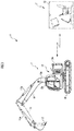
FIG. 1 is a schematic diagram illustrating the entire configuration of a remote operation system of a work machine according to an embodiment. -
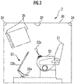
FIG. 2 is a schematic diagram illustrating the schematic configuration of a remote operation apparatus of the remote operation system ofFIG. 1 . -
FIG. 3 is a block diagram illustrating a configuration relating to control of the remote operation system ofFIG. 1 . -
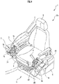
FIG. 4 is a perspective view illustrating the configuration of a seat and its surroundings in the work machine ofFIG. 1 . -
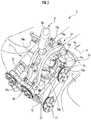
FIG. 5 is a perspective view of an operating mechanism of the work machine ofFIG. 1 . -
FIG. 6 is a plan view of the operating mechanism of the work machine ofFIG. 1 . -
FIG. 7 is a side view illustrating the schematic configuration of the operating mechanism of the work machine ofFIG. 1 . - Hereinbelow, a remote operation system S according to an embodiment will be described with reference to the drawings.
- First, the configuration of the remote operation system S will be described with reference to
FIG.s 1 to 3 . - As illustrated in
FIG. 1 , the remote operation system S comprises awork machine 1 which is a hydraulic excavator and a remote operation apparatus 2 for remotely operating thework machine 1. Thework machine 1 can be directly operated by an operator on board or can be indirectly operated through the remote operation apparatus 2 with no operator on board. - Note that, in the present embodiment, the hydraulic excavator is used as the work machine. However, the work machine of the present invention is not limited to the hydraulic excavator. For example, the work machine may also be a crane truck or a dump truck.
- The
work machine 1 comprises work equipment including aboom 10, anarm 11, and anattachment 12, aslewing structure 13 on which the work equipment is mounted, and anundercarriage 14 which slewably supports theslewing structure 13. - A proximal end portion of the
boom 10 is swingably attached to a front portion of theslewing structure 13. Theboom 10 includes a firsthydraulic cylinder 10a having an end attached to theboom 10 and an end attached to theslewing structure 13. Theboom 10 is swung relative to theslewing structure 13 through extension and contraction of the firsthydraulic cylinder 10a. - A proximal end portion of the
arm 11 is swingably attached to a distal end portion of theboom 10. Thearm 11 includes a secondhydraulic cylinder 11a having an end attached to thearm 11 and an end attached to theboom 10. Thearm 11 is swung relative to theboom 10 through extension and contraction of the secondhydraulic cylinder 11a. - The
attachment 12 is swingably attached to a distal end portion of thearm 11. Theattachment 12 includes a thirdhydraulic cylinder 12a having an end attached to theattachment 12 and an end attached to thearm 11. Theattachment 12 is swung relative to thearm 11 through extension and contraction of the thirdhydraulic cylinder 12a. - Note that, in the present embodiment, a bucket is used as the
attachment 12. However, theattachment 12 is not limited to the bucket and may be another kind of attachment (e.g., a crusher, a breaker, or a magnet). - The
slewing structure 13 is slewable around a yaw axis relative to theundercarriage 14 through a slewing hydraulic motor (not illustrated). Acab 13a for an operator to get in is provided in a front portion of theslewing structure 13, whereas a machine room 13b is provided in a rear portion of theslewing structure 13. - A slave-side operating device 15 (refer to
FIG. 2 ) for operating thework machine 1 is disposed in thecab 13a. The slave-side operating device 15 includes, for example, an operating pedal, an operating switch, and afourth operating lever 5 and a fifth operating lever 6 (refer toFIG. 4 ), which will be described later. - Hydraulic devices (not illustrated) such as a hydraulic pump, a direction selector valve, and a hydraulic oil tank, and an engine (not illustrated) as a power source of the hydraulic pump and the like are stored in the machine room 13b.
- The
undercarriage 14 is a crawler type undercarriage and driven by a traveling hydraulic motor (not illustrated). Note that the undercarriage of the work machine of the present invention is not limited to a crawler. For example, the undercarriage may move with wheels or legs. Further, in a case where the work machine is used on the water, the undercarriage may be, for example, a barge. - Note that the
work machine 1 may further include an actuator (e.g., a hydraulic actuator for driving a dozer or a hydraulic actuator included in an attachment such as a crusher) in addition to the traveling hydraulic motor, the slewing hydraulic motor, the firsthydraulic cylinder 10a, the secondhydraulic cylinder 11a, and the thirdhydraulic cylinder 12a described above. Further, some of the actuators of the work machine 1 (e.g., the slewing actuator) may be electric actuators. - In operating the
work machine 1, each of the actuators including the traveling hydraulic motor, the slewing hydraulic motor, the firsthydraulic cylinder 10a, the secondhydraulic cylinder 11a, and the thirdhydraulic cylinder 12a is activated by operating the slave-side operating device 15 with the engine running. For example, the activation of each actuator in response to the operation of the slave-side operating device 15 can be performed in a manner similar to that of a known work machine. - As illustrated in
FIG. 2 , thework machine 1 comprises, in thecab 13a, an electric operation driving device 16 (e.g., a first operating mechanism 7 and a second operating mechanism 8 (refer toFIG. 4 ), which will be described later) which drives the slave-side operating device 15 to enable remote operation. - The
operation driving device 16 is connected to the slave-side operating device 15. Note that theoperation driving device 16 may be detachable from thework machine 1. - The
operation driving device 16 includes a plurality of electric motors (not illustrated). Theoperation driving device 16 drives each of the operating pedal, the operating switch, and thefourth operating lever 5 and the fifth operating lever 6 (refer toFIG. 4 ), described later, which are included in the slave-side operating device 15, using a driving force from the electric motors. - The
work machine 1 further comprises anoperating state detector 17 for detecting the operating state of thework machine 1, anexternal sensor 18 which is, for example, a camera which detects a state around thework machine 1, and a slave-side control device 19 capable of executing various control processes. - The operating
state detector 17 is, for example, a detector which detects the rotation angle of the swing operation of each of theboom 10, thearm 11, and theattachment 12 or the stroke length of the firsthydraulic cylinder 10a, the secondhydraulic cylinder 11a, and the thirdhydraulic cylinder 12a, a detector which detects the slewing angle of the slewingstructure 13, a detector which detects the driving speed of theundercarriage 14, a detector which detects the tilt angle of the slewingstructure 13 or theundercarriage 14, or an inertial sensor which detects the angular velocity or acceleration of the slewingstructure 13. - The
external sensor 18 includes, for example, a camera, a range sensor, or a radar. The cameras or the like constituting theexternal sensor 18 are installed at a plurality of locations on, for example, a peripheral portion of the slewingstructure 13 so as to detect an object present around the slewingstructure 13. - The slave-
side control device 19 includes, for example, one or more electronic circuit units including a microcomputer, a memory, an interface circuit, and the like. The slave-side control device 19 appropriately acquires a detection signal of the operatingstate detector 17 and a detection signal of theexternal sensor 18. - The slave-
side control device 19 has, as functions implemented by both or one of hardware configurations mounted thereon and a program (software configuration), a function as anoperation control unit 19a, a function as a peripheral object detection unit 19b, and a function as a slave-side communication unit 19c. - The
operation control unit 19a controls the operation of thework machine 1 by controlling the activation of the operation driving device 16 (in turn, controlling the operation of the slave-side operating device 15) and controlling the operation of the engine in response to the operation of the slave-side operating device 15 or an operation command transmitted from the remote operation apparatus 2. - The peripheral object detection unit 19b detects, on the basis of a detection signal of the
external sensor 18, an object such as a person or an installed object which may be present in a predetermined target space around thework machine 1. - The slave-
side communication unit 19c appropriately performs wireless communication with the remote operation apparatus 2 via a master-side communication unit 27b, which will be described later. - As illustrated in
FIG. 3 , the remote operation apparatus 2 comprises, inside aremote operation room 20, a master-side seat 21 in which an operator sits, a pair of right and left master-side console boxes 22 which are disposed on right and left sides of the master-side seat 21, a master-side operating device 23 which is operated by the operator to remotely operate thework machine 1, aspeaker 24 serving as an output device for outputting acoustic information (auditory information), and adisplay 25 serving as an output device for outputting display information (visual information). - As illustrated in
FIG. 2 , the remote operation apparatus 2 further comprises anoperation state detector 26 for detecting the operation state of the master-side operating device 23 and a master-side control device 27 capable of executing various control processes. Note that the master-side control device 27 may be disposed either inside or outside theremote operation room 20. - The master-
side operating device 23 is, for example, configured to be the same as or similar to the slave-side operating device 15 of thework machine 1. - Specifically, the master-
side operating device 23 includes, for example, afirst operating lever 23b with an operating pedal 23a which is installed at the front of the master-side seat 21, and a second operating lever (not illustrated) and athird operating lever 23c which are respectively mounted on the pair of right and left master-side console boxes 22 so that an operator sitting in the master-side seat 21 can operate the master-side operating device 23. - However, the master-
side operating device 23 may be configured to be different from the slave-side operating device 15 of thework machine 1. For example, the master-side operating device 23 may be a portable operating device including, for example, a joystick or an operation button. - The
operation state detector 26 is, for example, a potentiometer or a contact switch incorporated in the master-side operating device 23. Theoperation state detector 26 is configured to output a detection signal indicating the operation state of each operating unit (e.g., the operating pedal 23a, thefirst operating lever 23b, the second operating lever, or thethird operating lever 23c) of the master-side operating device 23. - The
speakers 24 are, for example, disposed at a plurality of locations inside theremote operation room 20, such as the front part, the rear part, and both the right and left sides of theremote operation room 20. - The
display 25 includes, for example, a liquid crystal display or a head-up display. Thedisplay 25 is disposed forward of the master-side seat 21 so that an operator sitting in the master-side seat 21 can visually recognize thedisplay 25. - The master-
side control device 27 includes, for example, one or more electronic circuit units including a microcomputer, a memory, an interface circuit, and the like. The master-side control device 27 appropriately acquires a detection signal of theoperation state detector 26. The master-side control device 27 recognizes, on the basis of the detection signal, an operation command to thework machine 1, the operation command being determined by the operation state of the master-side operating device 23. - The master-
side control device 27 has, as functions implemented by both or one of hardware configurations mounted thereon and a program (software configuration), a function as an outputinformation control unit 27a and a function as a master-side communication unit 27b. - The output
information control unit 27a controls thespeaker 24 and thedisplay 25. - The master-
side communication unit 27b appropriately performs wireless communication with thework machine 1 via the slave-side communication unit 19c. The master-side control device 27 transmits, to the slave-side control device 19, an operation command to thework machine 1 and receives, from the slave-side control device 19, various pieces of information of the work machine 1 (e.g., an image captured by the camera, detection information about an object around the work machine, and detection information about the operating state of the work machine 1) through the wireless communication. - Next, the configuration of the first operating mechanism 7 and the
second operating mechanism 8 which are part of theoperation driving device 16 will be described with reference toFIG.s 4 to 7 . - As illustrated in
FIG. 4 , thework machine 1 comprises, inside thecab 13a, a slave-side seat 3 in which an operator sits and a pair of right and left slave-side console boxes 4 which are disposed on right and left sides of the slave-side seat 3. - The
work machine 1 further comprises the slave-side operating device 15 (refer toFIG. 2 ). The slave-side operating device 15 includes, for example, thefourth operating lever 5 and the fifth operating lever 6 which are provided on the respective slave-side console boxes 4, and an operating pedal. - The
work machine 1 further comprises the operation driving device 16 (refer toFIG. 2 ). Theoperation driving device 16 includes, for example, the first operating mechanism 7 (the operating mechanism for a work machine) for operating thefourth operating lever 5 and the second operating mechanism 8 (the operating mechanism for a work machine) for operating the fifth operating lever 6. - Further, inside the
cab 13a, a getting-in/outpassage 9 is formed forward of the slave-side seat 3 and the fifth operating lever 6. An operator passes through the getting-in/outpassage 9 when sitting in the slave-side seat 3. - The
fourth operating lever 5 and the fifth operating lever 6 are disposed in the front end portions of the respective slave-side console boxes 4. Further, the first operating mechanism 7 and thesecond operating mechanism 8 are attached to the front end portions of the respective slave-side console boxes 4 so as to respectively surround a base end portion of thefourth operating lever 5 and a base end portion of the fifth operating lever 6. - Of the right and left slave-side console boxes 4, the slave-side console box 4 located on the right side of the sitting operator (the left side in
FIG. 4 ) includes acontrol panel 4a which is provided at a position rearward of thefourth operating lever 5. An operating switch is disposed on thecontrol panel 4a. - The
fourth operating lever 5 and the fifth operating lever 6 transmit signals to the slave-side control device 19 (refer toFIG. 2 ) according to a tilt angle and a tilt direction. The slave-side control device 19 controls the operating amount of the work machine 1 (e.g., the swing angle of theboom 10 and thearm 11 in the present embodiment) on the basis of the signals. - The first operating mechanism 7 and the
second operating mechanism 8 respectively tilt thefourth operating lever 5 and the fifth operating lever 6 on the basis of an operation command from the remote operation apparatus 2. Specifically, the first operating mechanism 7 tilts thefourth operating lever 5 according to a tilt of the second operating lever (not illustrated) of the remote operation apparatus 2. On the other hand, thesecond operating mechanism 8 tilts the fifth operating lever 6 according to a tilt of thethird operating lever 23c (refer toFIG. 3 ) of the remote operation apparatus 2. - Hereinbelow, the first operating mechanism 7 and the
second operating mechanism 8 serving as the operating mechanism for a work machine will be described in detail. - As illustrated in the perspective view of
FIG. 5 and the plan view ofFIG. 6 , the first operating mechanism 7 comprises aplate 70 which is fixed to the slave-side console box 4 and asupport member 71 which tiltably supports thefourth operating lever 5 about an axis in a central portion on the upper face side of theplate 70. - The
plate 70 is a rectangular flat-shaped member. Theplate 70 installed in the slave-side console box 4 is parallel to a reference plane p (refer toFIG. 7 ), which will be described later. - The
support member 71 tiltably supports abase end portion 5a of thefourth operating lever 5 about an axis in the right-left direction as a first direction and the front-rear direction (the up-down direction inFIG. 6 ) as a second direction perpendicular to the first direction. - The first operating mechanism 7 further comprises a first actuator 72 (first direction actuator) which is disposed on the upper face side of the plate 70 (the front side in
FIG.s 5 and6 ) and a second actuator 73 (second direction actuator) which is disposed on the lower face side of the plate 70 (the back side inFIG.s 5 and6 ). - The
first actuator 72 and thesecond actuator 73 are electric actuators. Thefirst actuator 72 generates a driving force turning around an axis extending in the up-down direction from a rotation axis (not illustrated) set on the lower end thereof. Thesecond actuator 73 generates a driving force turning around an axis extending in the right-left direction from a rotation axis (not illustrated) set on the left end thereof. - The first operating mechanism 7 further comprises a first guide member 74 (first direction guide member) extending in the front-rear direction on the upper face side of the
plate 70 and a second guide member 75 (second direction guide member) extending in the right-left direction on the upper face side of theplate 70 and below thefirst guide member 74. - The
first guide member 74 includes a pair of front and rearfirst turning portions 74a and a pair of right and leftfirst guide portions 74b which are arch-shaped members. The pair offirst guide portions 74b extend in the front-rear direction with thebase end portion 5a of thefourth operating lever 5 interposed therebetween. Ends of each of thefirst guide portions 74b are attached to the respectivefirst turning portions 74a. - The
first turning portions 74a are turnable around a second axis a2 extending in the second direction. When thefirst turning portions 74a turn, thefirst guide portions 74b also turn integrally with thefirst turning portions 74a. As a result, thefirst guide portions 74b press thebase end portion 5a of thefourth operating lever 5 to tilt thefourth operating lever 5 in the right-left direction (first direction) along a first axis a1. - The
second guide member 75 includes a pair of right and leftsecond turning portions 75a and a pair of front and rearsecond guide portions 75b which are bar-shaped members. The pair ofsecond guide portions 75b extend in the right-left direction with thebase end portion 5a of thefourth operating lever 5 interposed therebetween. Ends of each of thesecond guide portions 75b are attached to the respectivesecond turning portions 75a. - The
second turning portions 75a are turnable around the first axis a1 extending in the first direction which is perpendicular to the second direction. When thesecond turning portions 75a turn, thesecond guide portions 75b also turn integrally with thesecond turning portions 75a. As a result, thesecond guide portions 75b press thebase end portion 5a of thefourth operating lever 5 to tilt thefourth operating lever 5 in the up-down direction (second direction) along the second axis a2. - The
second guide portions 75b of thesecond guide member 75 are located below thefirst guide portions 74b (the back side inFIG.s 5 and6 ). However, thefirst guide portions 74b of thefirst guide member 74 are formed in an arch shape extending along the second axis, the arch shape being centered on the first axis a1. Thus, even when thesecond guide member 75 turns, thesecond guide portions 75b do not come into contact with thefirst guide portions 74b. - Note that, in the first operating mechanism 7, the first direction corresponds to the right-left direction, and the second direction corresponds to the front-rear direction. That is, the first direction and the second direction are perpendicular to each other. However, the first direction and the second direction of the present invention are not limited to directions perpendicular to each other and may be any directions intersecting each other. Thus, the first direction and the second direction may be appropriately determined according to a direction in which the operating mechanism tilts the operating lever.
- Further, in the remote operation system S, the
first guide member 74 and thesecond guide member 75 configured in this manner tilt thefourth operating lever 5. However, the guide member of the present invention is not limited to one comprising thefirst guide member 74 and thesecond guide member 75. - For example, in a case where the operating lever tilts in a reciprocating manner only in one direction, only one guide member may be provided. Further, the guide member may not be turned to press the operating lever, but extended and contracted to press the operating lever.
- The first operating mechanism 7 further comprises a
first link mechanism 76 which is disposed on the upper face side of theplate 70 and below thefirst actuator 72 and thefirst guide member 74, and asecond link mechanism 77 which is disposed on the lower face side of theplate 70 and the opposite side of thesecond actuator 73 from the first actuator 72 (the right side inFIG. 6 ). - The
first link mechanism 76 transmits the driving force from thefirst actuator 72, the driving force being generated on the basis of the operation command, to thefirst guide member 74. Thesecond link mechanism 77 transmits the driving force from thesecond actuator 73, the driving force being generated on the basis of the operation command, to thesecond guide member 75. - As illustrated in
FIG. 4 , thesecond operating mechanism 8 basically has a configuration similar to that of the first operating mechanism 7. - However, the
second operating mechanism 8 differs from the first operating mechanism 7 in that a third actuator 80 (first direction actuator) corresponding to thefirst actuator 72 of the first operating mechanism 7 is disposed on the right side, and a fourth actuator 81 (third direction actuator) corresponding to thesecond actuator 73 of the first operating mechanism 7 is disposed on the rear side. - Driving forces generated by the
third actuator 80 and thefourth actuator 81 are transmitted to a third guide member 82 (first direction guide member) and a fourth guide member 83 (third direction guide member). Thesecond operating mechanism 8 tilts the fifth operating lever 6 in the front-rear direction (the up-down direction inFIG. 6 ) and the right-left direction (the third direction) on the basis of an operation command using the driving forces as with thefourth operating lever 5. - In this manner, in the
work machine 1, thefirst actuator 72 of the first operating mechanism 7 is disposed at the position on the opposite side of thefourth operating lever 5, which is operated by the first operating mechanism 7, from the slave-side seat 3. Further, thethird actuator 80 of thesecond operating mechanism 8 is disposed at the position on the opposite side of the fifth operating lever 6, which is operated by thesecond operating mechanism 8, from the slave-side seat 3. - In other words, in the
work machine 1, thefirst actuator 72 is disposed at the position more distant from the slave-side seat 3 than thefourth operating lever 5 is. Further, thethird actuator 80 is disposed at the position more distant from the slave-side seat 3 than the fifth operating lever 6 is. - Thus, in the
work machine 1, thefirst actuator 72 and thethird actuator 80 do not project toward the slave-side seat 3 even in a state where the first operating mechanism 7 and thesecond operating mechanism 8 are respectively attached to thefourth operating lever 5 and the fifth operating lever 6, thereby making it possible to leave a sufficient space on the slave-side seat 3 for an operator to sit in. - Further, as described above, in the
work machine 1, thesecond actuator 73 of the first operating mechanism 7 is disposed at the position on the opposite side of thefourth operating lever 5 from thecontrol panel 4a (the rear side inFIG. 4 , the upper side inFIG. 6 ). - Thus, the
second actuator 73 does not project to a region where thecontrol panel 4a is disposed. This enables thework machine 1 to prevent thesecond actuator 73 from obstructing an operation through thecontrol panel 4a. - Further, as described above, in the
work machine 1, thefourth actuator 81 is disposed rearward of the fifth operating lever 6. - Thus, the
fourth actuator 81 does not project toward the getting-in/outpassage 9. This enables thework machine 1 to prevent thefourth actuator 81 from obstructing an operator getting in and out. - As illustrated in
FIG. 7 , in the first operating mechanism 7, a tilt pivot point c is a pivot point of the tilt of thefourth operating lever 5. Further, a third axis a3 (reference axis) is a line which is perpendicular to a straight line, the straight line connecting the tip of the fourth operating lever 5 (the tip of atip portion 5b) tilted to the maximum extent to one side in the first direction and the tip of thefourth operating lever 5 tilted to the maximum extent to the other side in the first direction, and passes through the tilt pivot point c. Furthermore, the reference plane p is a plane which is perpendicular to the third axis a3 and passes through the tilt pivot point c. - The
first actuator 72 is disposed above the reference plane p (that is, on the same side of thefourth operating lever 5 as the reference plane p, the front side) when viewed in the direction of the second axis a2 (refer toFIG. 6 ). On the other hand, thesecond actuator 73 is disposed below the reference plane p (that is, on the opposite side of the reference plane p from thefourth operating lever 5, the rear side). - In addition, as illustrated in
FIG. 6 , an end portion on the lower side of thefirst actuator 72 and a lower end portion of thesecond actuator 73 overlap each other when viewed in the direction of the third axis a3. Thus, the size of the first operating mechanism 7 on the reference plane p is smaller than that of a conventional operating mechanism. - Also in the
second operating mechanism 8, thethird actuator 80 and thefourth actuator 81 are disposed at least partially overlapping each other when viewed in the reference axis direction in thesecond operating mechanism 8. - Thus, the first operating mechanism 7 and the
second operating mechanism 8 are smaller than a conventional operating mechanism. - This prevents the
first actuator 72, thesecond actuator 73, thethird actuator 80, and thefourth actuator 81 from projecting to regions such as the space on the slave-side seat 3 for an operator of thework machine 1 to sit in and the getting-in/outpassage 9 even in a state where the first operating mechanism 7 and thesecond operating mechanism 8 are attached, which enables a sufficient space to be left in these regions. - Further, it is possible to improve flexibility in the layout of components of the
work machine 1 including the first operating mechanism 7 and thesecond operating mechanism 8. - Furthermore, as illustrated in
FIG. 7 , thefourth operating lever 5 is tilted to operate thework machine 1. Thus, when viewed in the direction of the third axis a3, a space between thefourth operating lever 5 tilted to the maximum extent and the reference plane p (in a strict sense, the surface of the plate 70) is a dead space ds. - Thus, in the first operating mechanism 7, the
first actuator 72 is disposed in the dead space ds to utilize the dead space ds. Specifically, thefirst actuator 72 and thetip portion 5b of thefourth operating lever 5 at least partially overlap each other when viewed in the direction of the third axis a3 with thefourth operating lever 5 tilted to the maximum extent. This further downsizes the first operating mechanism 7. - Note that, also in the
second operating mechanism 8, thethird actuator 80 corresponding to thefirst actuator 72 of the first operating mechanism 7 is disposed in a dead space of the fifth operating lever 6. - In the present embodiment, the
first actuator 72 is disposed on the same side of the reference plane p as thefourth operating lever 5, whereas thesecond actuator 73 is disposed on the opposite side of the reference plane p from thefourth operating lever 5. - However, the first direction actuator and the second direction actuator of the present invention do not necessarily need to be disposed in this manner relative to the reference plane. For example, the first direction actuator and the second direction actuator may be disposed on one side of the reference plane.
- Further, in the present embodiment, the
first actuator 72 is disposed in the dead space ds. However, the first direction actuator of the present invention does not necessarily need to be disposed in the dead space. For example, the first direction actuator may be disposed outside the tip of the operating lever tilted to the maximum extent. - Although the illustrated embodiment has been described above, the present invention is not limited to such an embodiment.
- For example, in the above embodiment, the
control panel 4a is provided on the upper face of the slave-side console box 4 at the position rearward of thefourth operating lever 5. Along with this, in the first operating mechanism 7 attached to the slave-side console box 4, thesecond actuator 73 serving as the second direction actuator is disposed on the front side (the lower side inFIG. 6 ). - However, the operating mechanism of the present invention is not limited to such a configuration, and the second direction actuator may be provided at the position on the opposite side of the operating lever from the control panel. For example, in a case where the control panel is disposed forward of the operating lever in the console box, the second direction actuator may be disposed rearward of the operating lever.
- A work machine of the present invention is a work machine operated on the basis of an operation command, the work machine comprising:
- a seat for an operator to sit in;
- an operating lever for controlling an operating amount of the work machine according to a tilt angle and a tilt direction, the operating lever being disposed beside the seat; and
- an operating mechanism configured to tilt the operating lever on the basis of the operation command, in which
- the operating mechanism includes a first direction guide member configured to tilt the operating lever in a first direction, and a first direction actuator configured to generate a driving force for tilting the operating lever through the first direction guide member on the basis of the operation command, and
- the first direction actuator is disposed at a position on the opposite side of the operating lever from the seat.
- In this manner, in the work machine of the present invention, the first direction actuator is disposed at the position more distant from the seat than the operating lever is. Thus, according to the work machine of the present invention, the first direction actuator of the operating mechanism does not project toward the seat even in a state where the operating mechanism is attached to the operating lever, which makes it possible to leave a sufficient space on the seat for an operator to sit in.
- Preferably, the work machine of the present invention further comprises a control panel disposed forward or rearward of the operating lever, in which
- the operating mechanism includes a second direction guide member configured to tilt the operating lever in a second direction intersecting the first direction, and a second direction actuator configured to generate a driving force for titling the operating lever through the second direction guide member on the basis of the operation command, and
- the second direction actuator is disposed at a position on the opposite side of the operating lever from the control panel.
- To tilt the operating lever in a plurality of directions using the operating mechanism, a plurality of guide members which guide the operating lever in different directions and a plurality of actuators corresponding, one to one, to the guide members may be provided. In such a case, each of the actuators may be disposed at a position corresponding to the corresponding guide member at an orientation corresponding to a direction in which the corresponding guide member guides (tilts) the operating lever.
- Thus, if the first direction actuator is disposed at the position on the opposite side of the operating lever from the seat, and the second direction actuator is disposed at an orientation corresponding to the second direction which intersects the first direction corresponding to the first direction actuator, the second direction actuator may project to a region where the control panel is disposed and obstruct an operation through the control panel.
- Thus, when the second direction actuator is disposed at the position on the opposite side of the operating lever from the control panel as described above, the second direction actuator does not project to the region where the control panel is disposed. This makes it possible to prevent the second direction actuator of the operating mechanism from obstructing an operation through the control panel.
- Preferably, the work machine of the present invention further comprises a getting-in/out passage extending at a front of the seat and the operating lever, in which
- the operating mechanism includes a third direction guide member configured to tilt the operating lever in a third direction intersecting the first direction, and a third direction actuator configured to generate a driving force for titling the operating lever through the third direction guide member on the basis of the operation command, and
- the third direction actuator is disposed rearward of the operating lever.
- To tilt the operating lever in a plurality of directions using the operating mechanism, a plurality of guide members which guide the operating lever in different directions and a plurality of actuators corresponding, one to one, to the guide members may be provided. In such a case, each of the actuators may be disposed at a position corresponding to the corresponding guide member at an orientation corresponding to a direction in which the corresponding guide member guides (tilts) the operating lever.
- Thus, if the first direction actuator is disposed at the position on the opposite side of the operating lever from the seat, and the third direction actuator is disposed at an orientation corresponding to the third direction which intersects the first direction corresponding to the first direction actuator, the third direction actuator may project toward the getting-in/out passage through which an operator passes when sitting in the seat (project forward) and obstruct the operator getting in and out of the seat.
- Thus, when the third direction actuator is disposed rearward of the operating lever as described above, the third direction actuator does not project toward the getting-in/out passage. This makes it possible to prevent the third direction actuator of the operating mechanism from obstructing the operator getting in and out.
-
- 1
- work machine
- 2
- remote operation apparatus
- 3
- slave-side seat
- 4
- slave-side console box
- 4a
- control panel
- 5
- fourth operating lever
- 5a
- base end portion
- 5b
- tip portion
- 6
- fifth operating lever
- 7
- first operating mechanism (operating mechanism for work machine)
- 8
- second operating mechanism (operating mechanism for work machine)
- 9
- getting-in/out passage
- 10
- boom
- 10a
- first hydraulic cylinder
- 11
- arm
- 11a
- second hydraulic cylinder
- 12
- attachment
- 12a
- third hydraulic cylinder
- 13
- slewing structure
- 13a
- cab
- 13b
- machine room
- 14
- undercarriage
- 15
- slave-side operating device
- 16
- operation driving device
- 17
- operating state detector
- 18
- external sensor
- 19
- slave-side control device
- 19a
- operation control unit
- 19b
- peripheral object detection unit
- 19c
- slave-side communication unit
- 20
- remote operation room
- 21
- master-side seat
- 22
- master-side console box
- 23
- master-side operating device
- 23a
- operating pedal
- 23b
- first operating lever
- 23c
- third operating lever
- 24
- speaker
- 25
- display
- 26
- operation state detector
- 27
- master-side control device
- 27a
- output information control unit
- 27b
- master-side communication unit
- 70
- plate
- 71
- support member
- 72
- first actuator (first direction actuator)
- 73
- second actuator (second direction actuator)
- 74
- first guide member (first direction guide member)
- 74a
- first turning portion
- 74b
- first guide portion
- 75
- second guide member (second direction guide member)
- 75a
- second turning portion
- 75b
- second guide portion
- 76
- first link mechanism
- 77
- second link mechanism
- 80
- third actuator (first direction actuator)
- 81
- fourth actuator (third direction actuator)
- 82
- third guide member (first direction guide member)
- 83
- fourth guide member (third direction guide member)
- S
- remote operation system
- a1
- first axis
- a2
- second axis
- a3
- third axis (reference axis)
- c
- tilt pivot point
- ds
- dead space
- p
- reference plane
Claims (3)
- A work machine operated based on an operation command, the work machine comprising:a seat for an operator to sit in;an operating lever for controlling an operating amount of the work machine according to a tilt angle and a tilt direction, the operating lever being disposed beside the seat; andan operating mechanism configured to tilt the operating lever based on the operation command, whereinthe operating mechanism includes a first direction guide member configured to tilt the operating lever in a first direction, and a first direction actuator configured to generate a driving force for tilting the operating lever through the first direction guide member based on the operation command, andthe first direction actuator is disposed at a position on an opposite side of the operating lever from the seat.
- The work machine according to claim 1, comprising a control panel disposed forward or rearward of the operating lever, whereinthe operating mechanism includes a second direction guide member configured to tilt the operating lever in a second direction intersecting the first direction, and a second direction actuator configured to generate driving force for titling the operating lever through the second direction guide member based on the operation command, andthe second direction actuator is disposed at a position on an opposite side of the operating lever from the control panel.
- The work machine according to claim 1, comprising a getting-in and out passage extending at a front of the seat and the operating lever, whereinthe operating mechanism includes a third direction guide member configured to tilt the operating lever in a third direction intersecting the first direction, and a third direction actuator configured to generate driving force for titling the operating lever through the third direction guide member based on the operation command, andthe third direction actuator is disposed rearward of the operating lever.
Applications Claiming Priority (2)
| Application Number | Priority Date | Filing Date | Title |
|---|---|---|---|
| JP2019053621A JP7326796B2 (en) | 2019-03-20 | 2019-03-20 | working machine |
| PCT/JP2019/045982 WO2020188891A1 (en) | 2019-03-20 | 2019-11-25 | Work machine |
Publications (2)
| Publication Number | Publication Date |
|---|---|
| EP3904608A1 true EP3904608A1 (en) | 2021-11-03 |
| EP3904608A4 EP3904608A4 (en) | 2022-03-09 |
Family
ID=72520666
Family Applications (1)
| Application Number | Title | Priority Date | Filing Date |
|---|---|---|---|
| EP19920285.4A Withdrawn EP3904608A4 (en) | 2019-03-20 | 2019-11-25 | Work machine |
Country Status (5)
| Country | Link |
|---|---|
| US (1) | US12031297B2 (en) |
| EP (1) | EP3904608A4 (en) |
| JP (1) | JP7326796B2 (en) |
| CN (1) | CN113508204A (en) |
| WO (1) | WO2020188891A1 (en) |
Families Citing this family (2)
| Publication number | Priority date | Publication date | Assignee | Title |
|---|---|---|---|---|
| US20220316180A1 (en) * | 2021-04-05 | 2022-10-06 | Kobelco Construction Machinery Co., Ltd. | Remote driving device and operation mechanism for work machine |
| US20220341127A1 (en) * | 2021-04-26 | 2022-10-27 | Caterpillar Inc. | Multi-function joystick with asymmetric grip |
Family Cites Families (6)
| Publication number | Priority date | Publication date | Assignee | Title |
|---|---|---|---|---|
| JPH08249080A (en) * | 1995-03-07 | 1996-09-27 | Shin Caterpillar Mitsubishi Ltd | Automatic operation device for joy stick lever device |
| JPH1161887A (en) * | 1997-08-25 | 1999-03-05 | Ohbayashi Corp | Remote controller construction |
| JP2000075949A (en) * | 1998-08-28 | 2000-03-14 | Shin Caterpillar Mitsubishi Ltd | Control lever device |
| JP3798572B2 (en) | 1999-04-19 | 2006-07-19 | 日立建機株式会社 | Construction machinery cab |
| JP2009167673A (en) * | 2008-01-15 | 2009-07-30 | Hitachi Constr Mach Co Ltd | Work device |
| JP6641211B2 (en) | 2016-03-23 | 2020-02-05 | 大裕株式会社 | Heavy equipment remote control |
-
2019
- 2019-03-20 JP JP2019053621A patent/JP7326796B2/en active Active
- 2019-11-25 US US17/435,195 patent/US12031297B2/en active Active
- 2019-11-25 EP EP19920285.4A patent/EP3904608A4/en not_active Withdrawn
- 2019-11-25 WO PCT/JP2019/045982 patent/WO2020188891A1/en not_active Ceased
- 2019-11-25 CN CN201980093563.0A patent/CN113508204A/en active Pending
Also Published As
| Publication number | Publication date |
|---|---|
| EP3904608A4 (en) | 2022-03-09 |
| CN113508204A (en) | 2021-10-15 |
| JP7326796B2 (en) | 2023-08-16 |
| WO2020188891A1 (en) | 2020-09-24 |
| US12031297B2 (en) | 2024-07-09 |
| US20220145588A1 (en) | 2022-05-12 |
| JP2020154850A (en) | 2020-09-24 |
Similar Documents
| Publication | Publication Date | Title |
|---|---|---|
| JP7635615B2 (en) | Operating mechanism for work machine | |
| EP3904607A1 (en) | Operating mechanism for work machine and work machine equipped with same | |
| CN113039094B (en) | Peripheral monitoring device for construction machinery | |
| WO2019187560A1 (en) | Working machine control device | |
| JPWO2018123001A1 (en) | Work vehicle and work vehicle control system | |
| US12031297B2 (en) | Work machine | |
| US11821171B2 (en) | Work machine | |
| WO2024201617A1 (en) | Information input system for work machine | |
| US11959250B2 (en) | Manipulation mechanism for work machine and work machine equipped with same | |
| CN115198835A (en) | Remote drive device and operating mechanism for working machine | |
| JP7360581B2 (en) | Operating mechanism for working machines and working machines equipped with the same | |
| JP2025068502A (en) | Work machine and work system | |
| CN121712951A (en) | Engineering machine and operation system |
Legal Events
| Date | Code | Title | Description |
|---|---|---|---|
| STAA | Information on the status of an ep patent application or granted ep patent |
Free format text: STATUS: THE INTERNATIONAL PUBLICATION HAS BEEN MADE |
|
| PUAI | Public reference made under article 153(3) epc to a published international application that has entered the european phase |
Free format text: ORIGINAL CODE: 0009012 |
|
| STAA | Information on the status of an ep patent application or granted ep patent |
Free format text: STATUS: REQUEST FOR EXAMINATION WAS MADE |
|
| 17P | Request for examination filed |
Effective date: 20210730 |
|
| AK | Designated contracting states |
Kind code of ref document: A1 Designated state(s): AL AT BE BG CH CY CZ DE DK EE ES FI FR GB GR HR HU IE IS IT LI LT LU LV MC MK MT NL NO PL PT RO RS SE SI SK SM TR |
|
| A4 | Supplementary search report drawn up and despatched |
Effective date: 20220209 |
|
| RIC1 | Information provided on ipc code assigned before grant |
Ipc: G05G 9/047 20060101ALI20220203BHEP Ipc: E02F 9/20 20060101AFI20220203BHEP |
|
| DAV | Request for validation of the european patent (deleted) | ||
| DAX | Request for extension of the european patent (deleted) | ||
| STAA | Information on the status of an ep patent application or granted ep patent |
Free format text: STATUS: THE APPLICATION IS DEEMED TO BE WITHDRAWN |
|
| 18D | Application deemed to be withdrawn |
Effective date: 20220913 |