EP3904496B1 - Positioning method, positioning apparatus and sequencing system - Google Patents
Positioning method, positioning apparatus and sequencing system Download PDFInfo
- Publication number
- EP3904496B1 EP3904496B1 EP19905202.8A EP19905202A EP3904496B1 EP 3904496 B1 EP3904496 B1 EP 3904496B1 EP 19905202 A EP19905202 A EP 19905202A EP 3904496 B1 EP3904496 B1 EP 3904496B1
- Authority
- EP
- European Patent Office
- Prior art keywords
- mobile platform
- positioning
- reaction device
- moving
- limit
- Prior art date
- Legal status (The legal status is an assumption and is not a legal conclusion. Google has not performed a legal analysis and makes no representation as to the accuracy of the status listed.)
- Active
Links
Images


Classifications
-
- G—PHYSICS
- G02—OPTICS
- G02B—OPTICAL ELEMENTS, SYSTEMS OR APPARATUS
- G02B21/00—Microscopes
- G02B21/24—Base structure
-
- C—CHEMISTRY; METALLURGY
- C12—BIOCHEMISTRY; BEER; SPIRITS; WINE; VINEGAR; MICROBIOLOGY; ENZYMOLOGY; MUTATION OR GENETIC ENGINEERING
- C12Q—MEASURING OR TESTING PROCESSES INVOLVING ENZYMES, NUCLEIC ACIDS OR MICROORGANISMS; COMPOSITIONS OR TEST PAPERS THEREFOR; PROCESSES OF PREPARING SUCH COMPOSITIONS; CONDITION-RESPONSIVE CONTROL IN MICROBIOLOGICAL OR ENZYMOLOGICAL PROCESSES
- C12Q1/00—Measuring or testing processes involving enzymes, nucleic acids or microorganisms; Compositions therefor; Processes of preparing such compositions
- C12Q1/68—Measuring or testing processes involving enzymes, nucleic acids or microorganisms; Compositions therefor; Processes of preparing such compositions involving nucleic acids
- C12Q1/6869—Methods for sequencing
-
- B—PERFORMING OPERATIONS; TRANSPORTING
- B01—PHYSICAL OR CHEMICAL PROCESSES OR APPARATUS IN GENERAL
- B01J—CHEMICAL OR PHYSICAL PROCESSES, e.g. CATALYSIS OR COLLOID CHEMISTRY; THEIR RELEVANT APPARATUS
- B01J19/00—Chemical, physical or physico-chemical processes in general; Their relevant apparatus
- B01J19/18—Stationary reactors having moving elements inside
-
- G—PHYSICS
- G01—MEASURING; TESTING
- G01N—INVESTIGATING OR ANALYSING MATERIALS BY DETERMINING THEIR CHEMICAL OR PHYSICAL PROPERTIES
- G01N21/00—Investigating or analysing materials by the use of optical means, i.e. using sub-millimetre waves, infrared, visible or ultraviolet light
- G01N21/01—Arrangements or apparatus for facilitating the optical investigation
-
- G—PHYSICS
- G02—OPTICS
- G02B—OPTICAL ELEMENTS, SYSTEMS OR APPARATUS
- G02B21/00—Microscopes
- G02B21/24—Base structure
- G02B21/26—Stages; Adjusting means therefor
-
- G—PHYSICS
- G03—PHOTOGRAPHY; CINEMATOGRAPHY; ANALOGOUS TECHNIQUES USING WAVES OTHER THAN OPTICAL WAVES; ELECTROGRAPHY; HOLOGRAPHY
- G03B—APPARATUS OR ARRANGEMENTS FOR TAKING PHOTOGRAPHS OR FOR PROJECTING OR VIEWING THEM; APPARATUS OR ARRANGEMENTS EMPLOYING ANALOGOUS TECHNIQUES USING WAVES OTHER THAN OPTICAL WAVES; ACCESSORIES THEREFOR
- G03B5/00—Adjustment of optical system relative to image or object surface other than for focusing
-
- G—PHYSICS
- G01—MEASURING; TESTING
- G01N—INVESTIGATING OR ANALYSING MATERIALS BY DETERMINING THEIR CHEMICAL OR PHYSICAL PROPERTIES
- G01N35/00—Automatic analysis not limited to methods or materials provided for in any single one of groups G01N1/00 - G01N33/00; Handling materials therefor
- G01N2035/00178—Special arrangements of analysers
- G01N2035/00237—Handling microquantities of analyte, e.g. microvalves, capillary networks
-
- G—PHYSICS
- G01—MEASURING; TESTING
- G01N—INVESTIGATING OR ANALYSING MATERIALS BY DETERMINING THEIR CHEMICAL OR PHYSICAL PROPERTIES
- G01N21/00—Investigating or analysing materials by the use of optical means, i.e. using sub-millimetre waves, infrared, visible or ultraviolet light
- G01N21/62—Systems in which the material investigated is excited whereby it emits light or causes a change in wavelength of the incident light
- G01N21/63—Systems in which the material investigated is excited whereby it emits light or causes a change in wavelength of the incident light optically excited
- G01N21/64—Fluorescence; Phosphorescence
- G01N21/645—Specially adapted constructive features of fluorimeters
- G01N21/6456—Spatial resolved fluorescence measurements; Imaging
- G01N21/6458—Fluorescence microscopy
Definitions
- the present disclosure relates to the field of positioning, in particular to a positioning method, a positioning device and a sequencing system.
- embodiments of the present disclosure provide a positioning method according to claim 1 and a sequencing system according to claim 6.
- sequence determination refers to nucleic acid sequence determination, also known as sequencing, including DNA sequencing and/or RNA sequencing, and/or including long fragment sequencing and/or short fragment sequencing.
- sequence determination reaction refers to sequencing reaction.
- the reaction device 200 can be fixedly placed on the mobile platform 102, and the sequencing system 300 can introduce a reaction reagent/solution into the reaction device 200.
- the reaction device 200 is provided with one or more channels.
- the reaction reagent/solution is in the channel 200, and nucleic acid molecules are in the reaction reagent/solution.
- Imaging assembly 110 is arranged above the reaction device 200, such that images of nucleic acid molecules with an optically detectable label in a specific position (field of view) of the reaction device 200 can be acquired during the sequencing of nucleic acid molecules, wherein the optically detectable label is, e.g., a fluorescent molecule.
- the reaction device 200 is, e.g., a flowcell.
- the imaging assembly 110 comprises an automatic focusing module.
- the imaging assembly 110 is stationary, and mobile platform 102 drives the reaction device 200 to move in a plane perpendicular to the optical axis OP according to the information/instruction of the automatic focusing module, such that the imaging assembly 110 is able to acquire images of different positions of reaction device 200.
- the sequencing system 300 comprises a limit switch, a driving module (such as a step motor) and an inquiry board card to control the movement of the mobile platform 102 and give coordinate values of the mobile platform 102 or the reaction device 200.
- the step motor drives the mobile platform to move, and the inquiry board card outputs real-time coordinate values of the reaction device 200/mobile platform 102 according to the number of steps of the movement of the step motor.
- the limit switch is configured for limiting the extreme movement position of the mobile platform 102. Due to the relatively fixed positions of the mobile platform 102 and the reaction device 200, the limit switch can also limit the extreme movement position of the reaction device 200.
- the sequencing system 300 further comprises a mechanical stopper, which is arranged at one end of the stroke in the first direction approaching the limit switch and is configured for limiting the movement of the mobile platform 102.
- the sequencing system 300 in the photographing stage, can control the imaging assembly 110 to photograph the reaction device 200 so as to give fluorescence images of the nucleic acid molecules.
- the imaging assembly 110 may comprise a microscope and a camera that acquires light from the microscope.
- a lens e.g., an objective lens 112 of the microscope
- the first direction is a direction along the Y-axis.
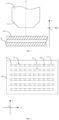
- the reaction device 200 is provided with a plurality of channels 21, as shown in FIG. 4 .
- any position of the first channel can be selected as the photographing start position, and the first channel can be set as required.
- the first channel and/or the second channel in FIG. 4 can be set as the first channel.
- the optical axis OP of the imaging assembly 110 can be made to be perpendicular to the first channel, and if required, then the mobile platform 102 can be moved in the direction of X-axis such that the optical axis OP of the imaging assembly 110 is perpendicular to a specific position of the first channel so as to photograph and acquire images of the specific position (field of view).
- the optical axis OP of the imaging assembly 110 is made to be perpendicular to a left end point 26 of the first channel 24 to start photographing.
- the type of limit switch used is not limited by the present application, and the limit switch can be inductive (such as a photoelectric or electromagnetic limit switch), a contact-type limit switch, or a combination of various limit switches.
- the limit switch is an electromagnetic limit switch, and the mobile platform 102 is provided with a magnetic element. When the electromagnetic limit switch senses the magnetic element, the limit switch experiences a contact action to realize circuit switching and disconnection of the power supply of the driving module, so that the mobile platform 102 can be considered to reach a first limit in a first direction.
- the limit switch is of specific precision, that is, the limit switch can sense the magnetic element within a certain distance range and respond, a position range is detected; moreover, when the driving module drives the mobile platform 102 to move at a relatively fast speed, although it is beneficial for fast positioning, there may also be great deviation in positioning due to larger inertia.
- a preset distance is a distance, on the stroke, between the first limit and the position of the mobile platform 102 when the preset relationship is satisfied. In this way, by moving from the first limit by the preset distance in step (d), the optical axis OP and the position of the reaction device 200 can satisfy the preset relationship.
Landscapes
- Chemical & Material Sciences (AREA)
- Physics & Mathematics (AREA)
- Life Sciences & Earth Sciences (AREA)
- Organic Chemistry (AREA)
- Proteomics, Peptides & Aminoacids (AREA)
- Analytical Chemistry (AREA)
- Health & Medical Sciences (AREA)
- General Physics & Mathematics (AREA)
- Zoology (AREA)
- Wood Science & Technology (AREA)
- Engineering & Computer Science (AREA)
- Biochemistry (AREA)
- General Health & Medical Sciences (AREA)
- Immunology (AREA)
- Optics & Photonics (AREA)
- Molecular Biology (AREA)
- Biotechnology (AREA)
- Microbiology (AREA)
- Biophysics (AREA)
- Bioinformatics & Cheminformatics (AREA)
- General Engineering & Computer Science (AREA)
- Genetics & Genomics (AREA)
- Chemical Kinetics & Catalysis (AREA)
- Pathology (AREA)
- Studio Devices (AREA)
- Container, Conveyance, Adherence, Positioning, Of Wafer (AREA)
- Investigating, Analyzing Materials By Fluorescence Or Luminescence (AREA)
Description
- The present disclosure relates to the field of positioning, in particular to a positioning method, a positioning device and a sequencing system.
- With the continuous development of nucleic acid sequencing technologies, sequencing systems are also continuously updated. For a sequencing system/platform that detects nucleic acid molecules to be detected in a reactor based on an optical imaging system, the sequencing system comprises an imaging assembly for continuously photographing nucleic acid molecules in a reactor (e.g., flowcell) during a sequencing reaction, and the photographed images are analyzed to give a sequencing result.
- In automated nucleic acid sequencing, it is desirable to ensure that the imaging assembly is able to acquire information about the target field of view through photographing, and continuously acquire information of all target fields of view in a predetermined range in one circle of sequencing reaction or one sequencing reaction, and at the beginning, automatic and accurate adjustment and determination of the relative positions of the imaging assembly and the reactor is very important. Therefore, it is necessary to provide a positioning method.
- A method of high-speed positioning of a linear stage is disclosed in the paper from Y. Nakamura et at, "high-speed positioning of a linear stage using feedback error learning control: Improvement of learning time and accuracy", International Technology (ICIT), 2012 IEEE, pages 1079-1085, DOI: 10.1109/ICIT.2012.6210083.
- Therefore, embodiments of the present disclosure provide a positioning method according to claim 1 and a sequencing system according to
claim 6. - The additional aspects and advantages of the embodiments of the present disclosure will be partially set forth in the following description, and will partially become apparent from the following description or be appreciated by practice of the embodiments of the present disclosure.
- The aforementioned and/or additional aspects and advantages of embodiments of the present disclosure will become apparent and easily understood from the description of the embodiments in reference to the following drawings, among which:
-
FIG. 1 is a flowchart of a positioning method according to an embodiment of the present disclosure; -
FIG. 2 is a structural schematic diagram of a sequencing system according to an embodiment of the present disclosure; -
FIG. 3 is a structural schematic diagram of a portion of a sequencing system according to an embodiment of the present disclosure; -
FIG. 4 is a structural schematic diagram of a reaction device according to an embodiment of the present disclosure; -
FIG. 5 is a schematic diagram showing the relationship between moving speed and deviation of a mobile platform according to an embodiment of the present disclosure; -
FIG. 6 is a schematic diagram of a module of a sequencing system according to an embodiment of the present disclosure; and -
FIG. 7 is a schematic diagram of another block of a sequencing system according to an embodiment of the present disclosure. - The embodiments of the present disclosure are described in detail below, and the examples of the embodiments are shown in the accompanying drawings, throughout which identical or similar reference numerals represent identical or similar elements or elements having identical or similar functions. The embodiments described below by reference to the accompanying drawings are exemplary and are merely intended to explain the present disclosure rather than be construed as limiting the present disclosure.
- In the description of the present disclosure, the terms "first" and "second" are used for description purpose only rather than construed as indicating or implying relative importance or implicitly indicating the number of indicated technical features. Therefore, features defined with "first" and "second" may explicitly or implicitly include one or more of the features. In the description of the present disclosure, unless otherwise specifically defined, "a plurality of" means two or more than two.
- In the description of the present disclosure, it should be noted that unless otherwise clearly specified and defined, "connect" should be comprehended in its broad sense. For example, "connect" may be "fixedly connect", "detachably connect" or "integrally connect"; "mechanically connect", "electrically connect" or "communicate with each other"; or "directly interconnect", "indirectly interconnect through an intermediate", "the communication between the interiors of two elements" or "the interaction between two elements". For those of ordinary skill in the art, the specific meanings of the aforementioned terms in the present disclosure can be understood according to specific conditions.
- The following disclosure provides many different embodiments or examples for implementing different structures of the present disclosure. To simplify the disclosure of the present disclosure, components and settings of certain examples are described below. In addition, the present disclosure may repeat reference numbers and/or reference letters in different examples. Such repetition is intended for simplicity and clarity rather than for indicating the relationship between various embodiments and/or settings discussed.
- The "sequence determination" refers to nucleic acid sequence determination, also known as sequencing, including DNA sequencing and/or RNA sequencing, and/or including long fragment sequencing and/or short fragment sequencing. The "sequence determination reaction" refers to sequencing reaction.
- Referring to
FIG. 1 , an embodiment of the present disclosure provides a positioning method for ansequencing system 300. Referring toFIG. 2 , thesequencing system 300 comprises animaging assembly 110 and amobile platform 102; theimaging assembly 110 comprises an optical axis OP, and themobile platform 102 bears areaction device 200; theimaging assembly 110 is located above thereaction device 200, a limit switch is configured for controlling stroke of themobile platform 102 in a first direction, and the stroke comprises a first limit; the method comprises: - (a) moving the
mobile platform 102 in a direction approaching the first limit at a first step space until a distance between a current position of thereaction device 200 and a previous position of thereaction device 200 is smaller than the first step space; - (b) moving the
mobile platform 102 in a direction opposite to the moving direction in (a); - (c) moving the
mobile platform 102 in the moving direction in (a) until themobile platform 102 reaches the first limit; and - (d) moving the
mobile platform 102 in the direction opposite to the moving direction in (a) for a preset distance such that the optical axis OP and the position of thereaction device 200 satisfy a preset relationship. - The positioning method described above comprises setting a moving speed/a moving step space, and by moving the mobile platform back and forth in the first direction, rapid and precise positioning can be realized, such that the optical axis of the
imaging assembly 110 and the position of thereaction device 200 satisfy the preset relationship, and thereby subsequently theimaging assembly 110 can continuously photograph to give information of all target fields of view in a predetermined area. - Specifically, referring to
FIG. 2 , in some examples, thereaction device 200 can be fixedly placed on themobile platform 102, and thesequencing system 300 can introduce a reaction reagent/solution into thereaction device 200. Thereaction device 200 is provided with one or more channels. The reaction reagent/solution is in thechannel 200, and nucleic acid molecules are in the reaction reagent/solution.Imaging assembly 110 is arranged above thereaction device 200, such that images of nucleic acid molecules with an optically detectable label in a specific position (field of view) of thereaction device 200 can be acquired during the sequencing of nucleic acid molecules, wherein the optically detectable label is, e.g., a fluorescent molecule. Thereaction device 200 is, e.g., a flowcell. - In some embodiments, the
imaging assembly 110 comprises an automatic focusing module. When the automatic focusing module is used for focusing on a specific position of the reaction device, theimaging assembly 110 is stationary, andmobile platform 102 drives thereaction device 200 to move in a plane perpendicular to the optical axis OP according to the information/instruction of the automatic focusing module, such that theimaging assembly 110 is able to acquire images of different positions ofreaction device 200. Generally, thesequencing system 300 comprises a limit switch, a driving module (such as a step motor) and an inquiry board card to control the movement of themobile platform 102 and give coordinate values of themobile platform 102 or thereaction device 200. The step motor drives the mobile platform to move, and the inquiry board card outputs real-time coordinate values of thereaction device 200/mobile platform 102 according to the number of steps of the movement of the step motor. The limit switch is configured for limiting the extreme movement position of themobile platform 102. Due to the relatively fixed positions of themobile platform 102 and thereaction device 200, the limit switch can also limit the extreme movement position of thereaction device 200. In another embodiment, thesequencing system 300 further comprises a mechanical stopper, which is arranged at one end of the stroke in the first direction approaching the limit switch and is configured for limiting the movement of themobile platform 102. - When the optical axis OP and the position of the
reaction device 200 satisfy a preset relationship, thesequencing system 300, in the photographing stage, can control theimaging assembly 110 to photograph thereaction device 200 so as to give fluorescence images of the nucleic acid molecules. Theimaging assembly 110 may comprise a microscope and a camera that acquires light from the microscope. - Referring to the coordinate system shown in
FIG. 3 , before the positioning starts or at the start of the positioning, a lens (e.g., anobjective lens 112 of the microscope) of theimaging assembly 110 is moved to a 0 point position of Z-axis, such as any position that is away from thereaction device 200 by certain distance in the Z-axis direction and is relatively in the middle of the X-axis direction, to prevent theobjective lens 112 from colliding with thereaction device 200 below and the structures on both sides. The first direction is a direction along the Y-axis. - In some embodiments, the
reaction device 200 is provided with a plurality ofchannels 21, as shown inFIG. 4 . Generally, any position of the first channel can be selected as the photographing start position, and the first channel can be set as required. For example, the first channel and/or the second channel inFIG. 4 can be set as the first channel. By using the positioning method of the present embodiment, the optical axis OP of theimaging assembly 110 can be made to be perpendicular to the first channel, and if required, then themobile platform 102 can be moved in the direction of X-axis such that the optical axis OP of theimaging assembly 110 is perpendicular to a specific position of the first channel so as to photograph and acquire images of the specific position (field of view). For example, from top to bottom inFIG. 4 , the optical axis OP of theimaging assembly 110 is made to be perpendicular to aleft end point 26 of thefirst channel 24 to start photographing. - The type of limit switch used is not limited by the present application, and the limit switch can be inductive (such as a photoelectric or electromagnetic limit switch), a contact-type limit switch, or a combination of various limit switches. In one example, the limit switch is an electromagnetic limit switch, and the
mobile platform 102 is provided with a magnetic element. When the electromagnetic limit switch senses the magnetic element, the limit switch experiences a contact action to realize circuit switching and disconnection of the power supply of the driving module, so that themobile platform 102 can be considered to reach a first limit in a first direction. Generally, since the limit switch is of specific precision, that is, the limit switch can sense the magnetic element within a certain distance range and respond, a position range is detected; moreover, when the driving module drives themobile platform 102 to move at a relatively fast speed, although it is beneficial for fast positioning, there may also be great deviation in positioning due to larger inertia. - In one example, according to multiple tests, as shown in Table 1, when the
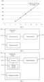
mobile platform 102 is set to reach the first limit at speeds V = 12.8 mm/s and V = 2 mm/s, the deviation between the two coordinates (Y-axis coordinates) of the first limits can reach 1000 µm. Table 1, based on the tests performed by the inventors, shows the difference between the coordinate values of the reaction device 200 (or the mobile platform 102) obtained when reaching the same position (for example, the first limit) at different speeds.FIG. 5 is a curve fitted according to the data in Table 1. The abscissa represents the speed, and the ordinate represents the difference value between the average coordinate value and the average coordinate value when the speed is 2 mm/s. It can be seen that the speed and the difference value (or average coordinate value of multiple measurements) satisfies the linear relationship.Table 1 Unit of speed mm/s Unit of coordinate value µm Speed Coordinate value 1 Coordinate value 2Coordinate value 3 Average value Difference value between the average value and that when the speed is 2 mm/s 12.864 46292 46339 46319 46317 1061 10 45958 45943 45966 45956 700 8 45723 45722 45744 45730 474 6 45532 45534 45521 45529 273 4 45353 45341 45359 45351 95 2 45258 45263 45246 45256 0 - The moving speed in step (a) is not limited. Preferably, in some examples, in order to position quickly, in step (a), the
mobile platform 102 can be set to move at a faster moving speed, and the first step space can be set/selected arbitrarily within a range less than the allowable stroke range of themobile platform 102. In some examples, the allowable stroke range of themobile platform 102 is about 15 cm, the first step space of themobile platform 102 is less than 15 cm, and the first step space can be set to 10 cm, 8 cm, 5 cm, 3 cm, 2 cm, 1 cm, etc. In one example, the moving speed of the mobile platform 102 (V1) is 12.8 mm/s, and the first step space (Space 1) is 2800 um, which is the space between two adjacent channels. - When the distance between the current position P2 of the
reaction device 200 and the previous position P1 of thereaction device 200 is smaller than the first step space, that is, when P2 - P1 < Space 1, that is, when themobile platform 102 has not completed the step space, the limit switch is triggered to turn on so as to stop the movement of themobile platform 102. - The moving speed of the
mobile platform 102 in step (b) is not limited. In some examples, setting the moving direction in step (b) to be opposite to the moving direction in step (a) is to eliminate or reduce the influence of the moving speed in step (a) and detection precision of the limit switch on positioning. A minimum distance themobile platform 102 needs to move in step (b) is related to the moving speed of themobile platform 102 in step (a). Generally, the moving distance in step (b) is smaller compared to that in step (a). In step (b), a moving speed less than that in step (a) can be adopted. For example, the moving speed in step (a) is 12.8 mm/s, and the moving speed in step (b) can be set to be less than 12 mm/s, such as 10 mm/s, 8 mm/s, 6 mm/s, 4 mm/s or 2 mm/s. - Specifically, after the completion of step (a), a deviation is present between the coordinate values of the mobile platform 102 (or the reaction device 200) that are fed back and the actual position of the
mobile platform 102 due to such reasons as the influence of the detection accuracy of the limit switch and the moving speed of themobile platform 102. The actual position of themobile platform 102 may exceed or fail to reach the coordinate position. Therefore, the step (b) is performed, in which themobile platform 102 is moved in a direction opposite to the moving direction in step (a) for a certain distance, which can eliminate or reduce the positioning deviation caused by the moving speed of themobile platform 102 in step (a). Generally, in step (a), the faster the moving speed of themobile platform 102 is, the greater the inertia is and thereby the greater the resulting positioning deviation will be. Accordingly, in step (b), the distance of moving themobile platform 102 in the direction opposite to the moving direction in step (a) can be set to a larger value. In one example, the positioning deviation caused by the moving speed in step (a) is about 800 µm, and the moving distance of themobile platform 102 in step (b) can be set to be no less than 800 µm. For example, the moving distance in step (b) is set to 1000 µm, 1200 µm, 1500 µm, 2000 µm, or the like. - In some examples, the moving speed of the
mobile platform 102 in step (c) is not greater than a first preset value, and the first preset value is related to an allowable error of positioning. Specifically, the reason of setting the first preset value is to allow the deviation between the actual position of themobile platform 102 and the coordinate position is within an allowable error range of the positioning when the first limit is reached. The allowable error of the positioning is the space between the target positions in the moving direction. In one example, the allowable error of the positioning is the width of achannel 24, the length of the channel in the first direction (moving direction) is defined as the width of achannel 21, and the width of thechannel 24 is 1.8 mm; based on the relationship between moving speed and deviation shown inFIG. 5 , the first preset value can be set to 11.6 mm/s. - Specifically, in one example, it is desired to eliminate the position deviation caused by the moving speed of the
mobile platform 102 in step (a) and/or step (b) by controlling the moving speed of themobile platform 102 in step (c). The first preset value may be less than or equal to the moving speed of themobile platform 102 in step (a). In one example, the error due to mechanical movement is allowed to be ±0.7 mm in positioning. The first preset value can be set to 9.8 mm/s. - In some examples, preferably, in step (c), the
mobile platform 102 can be moved at a relatively low speed, such as at a moving speed less than 5 mm/s, 3 mm/s, etc., so that the deviation caused by this step is not greater than one-eighth, one-tenth, one-fifteenth, etc. of the allowable error of the positioning, and the error is basically negligible. Thus, in step (d), the mobile platform can be moved at a relatively fast speed and can reach the target position within the allowable error range of the positioning. In one example, the allowable error of the positioning is the width of thechannel 24, and the width of thechannel 24 is 1.8 mm; the mechanical tolerance caused by thereaction device 200, themobile platform 102 and the mechanical connection positioning structure is about ±0.2 mm, and the error due to mechanical movement is allowed to be ±0.7 mm in positioning. - In certain embodiments, the moving speed of the
mobile platform 102 in step (c) is not greater than the moving speed of themobile platform 102 in step (a). Thus, the moving speed of themobile platform 102 in step (c) may also eliminate or partially eliminate the position deviation caused by the moving speed of themobile platform 102 in step (a). - Considering the deviation caused by the detection precision of the limit switch and the moving speed during mechanical positioning is beneficial for precise positioning. The positioning method comprises steps (a)-(c) to eliminate or reduce the influence of the detection precision of the limit switch and the moving speed of the
mobile platform 102 in these steps on precise positioning. - The moving speed of the
mobile platform 102 in step (d) is not greater than a second preset value, and the second preset value is related to an allowable error of positioning. In some examples, thereaction device 200 is provided with one ormore channels 21, the positioning is for enabling fields of view acquired by theimaging assembly 110 to be from the channels, the allowable error of the positioning is related to the width of the channel, and the width of the channel is defined as the length of thechannel 21 in the first direction. Specifically, in order to enable the optical axis OP and the starting position of thereaction device 200 to satisfy a preset relationship, such as a perpendicular relationship, the second preset value is used as the upper limit of the moving speed of themobile platform 102 in step (d), and this limit can enable the positioning deviation caused by the moving speed of themobile platform 102 in step (d) to be within the allowable error range of the positioning. - In this embodiment, when positioning a batch of
reaction devices 200 with the same specification and dimension, only any one of thereaction devices 200 placed on themobile platform 102 needs to be subjected to channel positioning. After the positioning is completed, the coordinates are recorded and saved. When areaction device 200 with the same specification and dimension is used, themobile platform 102 can be directly used to move thereaction device 200 to the saved coordinate position to realize the initial positioning, which can save a lot of time for sequence determination. In some examples, the mechanical tolerance among thereaction devices 200 with the same specification and dimension is 0.1 mm. In one example, the positioning method is to achieve precise positioning of a target position. The target position is, for example, any field of view in a certain channel on thereaction device 200. The width of the channel is 1.8 mm, and the allowable error of the positioning is ±0.9 mm, such that theimaging assembly 110 can acquire images of the target position. The tolerance among thereaction devices 200 with the same specification and that of the related mechanical structure are ±0.2 mm. Therefore, it will be appreciated that the allowable deviation of the entire movement process shall not exceed ±0.7 mm if the positioning of the target position is to be achieved. - In certain embodiments, the positioning is for enabling fields of view acquired by the
imaging assembly 110 to be from a designated channel on thereaction device 200, and the second preset value is related to the width of the designated channel. In this way, theimaging assembly 110 can acquire images of the designated channel of thereaction device 200. - In the above example, the designated channel may be a
first channel 24 of thereaction device 200. More specifically, aleft end position 26 of thefirst channel 24 may be used as the starting position of photographing for theimaging assembly 110. Photographingpositions 28 comprising the startingposition 26 may be used as fields of view (FOVs) of theimaging assembly 110. - In some examples, a preset distance is a distance, on the stroke, between the first limit and the position of the
mobile platform 102 when the preset relationship is satisfied. In this way, by moving from the first limit by the preset distance in step (d), the optical axis OP and the position of thereaction device 200 can satisfy the preset relationship. - Specifically, in the example described above, the optical axis OP and the
first channel 24 of thereaction device 200 can satisfy a perpendicular relationship. The preset distance can be measured in advance before moving themobile platform 102, and recorded and saved for use when needed. - It should be noted that in the coordinate system shown in the figure, the position of the
mobile platform 102 can be obtained by an inquiry board card, and the inquiry board card can provide the coordinate values according to the number of steps of the movement of the motor that drives themobile platform 102 to move. In an example, the frequency of the inquiry board card to calculate and output coordinate values is 20 ms. - In certain embodiments, the positioning method comprises: prompting information of success when the optical axis OP and the position of the
reaction device 200 satisfy a preset relationship. In this way, when the positioning of thereaction device 200 is successful, the user can continue subsequent operations in time, which improves the efficiency of sequence determination. - Specifically, the information of success can be prompted by sound and/or light. For example, the
sequencing system 300 comprises a speaker and/or a display screen, and when the optical axis OP and the position of thereaction device 200 satisfy the preset relationship, the speaker can play the information of success, and the display screen can display the information of success, etc. Of course, thesequencing system 300 may also comprise a vibrating element. When the optical axis OP and the position of thereaction device 200 satisfy the preset relationship, the vibrating element vibrates to prompt the information of success. - Referring to
FIG. 2 andFIG. 6 , an embodiment of the present disclosure provides asequencing system 300. Thesequencing system 300 comprises apositioning device 302, animaging assembly 110 and amobile platform 102; theimaging assembly 110 comprises an optical axis OP, and themobile platform 102 bears areaction device 200; theimaging assembly 110 is located above thereaction device 200, a limit switch is configured for controlling stroke of themobile platform 102 in a first direction, and the stroke comprises a first limit; thepositioning device 302 is configured for: - (a) moving the
mobile platform 102 in a direction approaching the first limit at a first step space until a distance between a current position of thereaction device 200 and a previous position of thereaction device 200 is smaller than the first step space; - (b) moving the
mobile platform 102 in a direction away from the first limit; - (c) moving the
mobile platform 102 in a direction approaching the first limit until themobile platform 102 reaches the first limit; and - (d) moving the
mobile platform 102 in the direction away from the first limit for a preset distance such that the optical axis OP and the position of thereaction device 200 satisfy a preset relationship. - The
sequencing system 300 described above, by thepositioning device 302 comprised therein, enables themobile platform 102 to move back and forth in the first direction. Thus, in combination with setting a moving speed/a moving step space, rapid and precise positioning can be realized, such that the optical axis of theimaging assembly 110 and the position of thereaction device 200 satisfy the preset relationship, and thereby subsequently theimaging assembly 110 can continuously photograph to give information of all target fields of view in a predetermined area. - It should be noted that the explanation and description of the technical features and benefits of the positioning method in any of the aforementioned embodiments and examples are also applicable to the
sequencing system 300 according to the present embodiment. There will be no detailed description herein to avoid redundancy. - In certain embodiments, the moving speed of the mobile platform in step (c) is not greater than a first preset value, and the first preset value is related to an allowable error of positioning.
- In certain embodiments, the moving speed of the mobile platform in step (c) is not greater than the moving speed of the mobile platform in step (a).
- In certain embodiments, a minimum distance the mobile platform needs to move in step (b) is related to the moving speed of the mobile platform in step (a).
- In certain embodiments, the moving speed of the mobile platform in step (d) is not greater than a second preset value, and the second preset value is related to an allowable error of positioning.
- In certain embodiments, the reaction device is provided with one or more channels, the allowable error of the positioning is related to the width of the channel, and the width of the channel is defined as the length of the channel in the first direction.
- In certain embodiments, the positioning device is configured for prompting information of success when the optical axis and the position of the reaction device satisfy a preset relationship.
- Referring to
FIG. 7 , an embodiment of the present disclosure provides apositioning device 302 for asequencing system 300. Thesequencing system 300 comprises animaging assembly 110 and amobile platform 102; theimaging assembly 110 comprises an optical axis OP, and themobile platform 102 bears areaction device 200; theimaging assembly 110 is located above thereaction device 200, a limit switch is configured for controlling stroke of themobile platform 102 in a first direction, and the stroke comprises a first limit. Thepositioning device 302 comprises astorage device 304 and aprocessor 306; the storage device is configured for storing data that comprises a computer-executable program, and the processor is configured for executing the computer-executable program, wherein executing the computer-executable program comprises performing the steps of the positioning method of any one of the embodiments described above. - In addition, the
sequencing system 300 shown inFIG. 7 comprises thepositioning device 302. - An embodiment of the present disclosure provides a computer-readable storage medium configured for storing a program that, when executed by a computer, causes the computer to perform the method according to any one of the embodiments described above. The computer-readable storage medium may include: read-only memory, random access memory, magnetic disk, optical disk, or the like.
- In the description of this specification, the description with reference to the terms "one embodiment", "certain embodiments", "exemplary embodiments", "example", "specific example", or "some examples" means that the specific features, structures, materials or characteristics described in combination with the embodiments or examples are included in at least one embodiment or example of the present disclosure. In this specification, the schematic description of the aforementioned terms do not necessarily refer to the same embodiment or example. Moreover, the particular features, structures, materials or characteristics described may be combined in any one or more embodiments or examples in any appropriate manner.
- Logic and/or steps shown in the flowcharts or otherwise described herein, for example, may be considered as a sequencing list of executable instructions that are used to implement logical functions, and may be specifically implemented in any computer-readable storage medium for use by an instruction execution system, device, or apparatus (for example, a computer-based system, a system including a processor, or another system that can get instructions from the instruction execution system, device, or apparatus and execute the instructions), or for use in combination with the instruction execution system, device or apparatus. As used herein, the "computer-readable storage medium" may be any device that may include, store, communicate, propagate, or transmit a program for use by an instruction execution system, device, or apparatus, or for use in combination with the instruction execution system, device, or apparatus.
- In addition, each functional unit in each embodiment of the present disclosure may be integrated in one processing module, or each unit may physically exist alone, or two or more than two units may be integrated in one module. The above-mentioned integrated module may be implemented in the form of hardware or in the form of a software functional module. The integrated module may also be stored in a computer-readable storage medium if it is implemented in the form of a software functional module and is sold or used as standalone products.
- Although the embodiments of the present disclosure have been shown and described above, it will be appreciated that the aforementioned embodiments are exemplary and are not to be construed as limiting the present disclosure, and that those of ordinary skill in the art may make changes, modifications, replacements and variations to such embodiments without departing from the scope of the present disclosure.
Claims (10)
- A positioning method for a sequencing system, wherein the sequencing system comprises an imaging assembly (110) and a mobile platform (102), the imaging assembly (110) comprises an optical axis, the mobile platform (102) bears a reaction device (200), the imaging assembly (110) is located above the reaction device (200), a limit switch is configured for controlling a stroke of the mobile platform (102) in a first direction, thereby defining a first limit of the stroke, and the stroke comprises a first limit, the method comprising:(a) moving the mobile platform (102) in a direction approaching the first limit at a first step space until a distance between a current position (P2) of the reaction device (200) and a previous position (P1) of the reaction device (200) is smaller than the first step space, due to the limit switch being triggered to turn on so as to stop the movement of the mobile platform;(b) moving the mobile platform (102) in a direction opposite to the moving direction in (a), wherein a minimum distance the mobile platform (102) needs to move in step (b) is related to a moving speed of the mobile platform (102) in step (a) to eliminate or reduce the positioning deviation caused by the moving speed of the mobile platform in step (a);(c) moving the mobile platform (102) in the moving direction in (a) until the mobile platform (102) reaches the first limit, wherein a moving speed of the mobile platform (102) in step (c) is not greater than a first preset value, and the first preset value is related to an allowable error of the positioning; and(d) moving the mobile platform (102) in the direction opposite to the moving direction in (a) for a preset distance such that the optical axis (OP) and the position of the reaction device (200) satisfy a preset relationship
- The method according to claim 1, wherein the moving speed of the mobile platform (102) in step (c) is not greater than a moving speed of the mobile platform (102) in step (a).
- The method according to claim 1 or 2, wherein a moving speed of the mobile platform (102) in step (d) is not greater than a second preset value, and the second preset value is related to the allowable error of the positioning.
- The method according to any of claims 1-3, wherein the reaction device (200) is provided with one or more channels, the positioning is for enabling fields of view acquired by the imaging assembly (110) to be from the channels, the allowable error of the positioning is related to the width of the channel, and the width of the channel is defined as the length of the channel in the first direction.
- The method according to any of claims 1-4, wherein the method further comprises: prompting information of success when the optical axis (OP) and the position of the reaction device (200) satisfy the preset relationship.
- A sequencing system, comprising a positioning device (302), an imaging assembly (110) and a mobile platform (102), wherein the imaging assembly (110) comprises an optical axis (OP), the mobile platform (102) bears a reaction device (200), the imaging assembly (110) is located above the reaction device (200), a limit switch is configured for controlling a stroke of the mobile platform (102) in a first direction, thereby defining a first limit for the stroke, the stroke comprises a first limit, and the positioning device (302) is configured for:(a) moving the mobile platform (102) in a direction approaching the first limit at a first step space until a distance between a current position of the reaction device (200) and a previous position of the reaction device (200) is smaller than the first step space, due to the limit switch being triggered to turn on so as to stop the movement of the mobile platform;(b) moving the mobile platform (102) in a direction away from the first limit, wherein a minimum distance the mobile platform (102) needs to move in step (b) is related to a moving speed of the mobile platform (102) in step (a) to eliminate or reduce the positioning deviation caused by the moving speed of the mobile platform in step (a);(c) moving the mobile platform (102) in a direction approaching the first limit until the mobile platform (102) reaches the first limit, wherein a moving speed of the mobile platform (102) in step (c) is not greater than a first preset value, and the first preset value is related to an allowable error of the positioning; and(d) moving the mobile platform (102) in the direction away from the first limit for a preset distance such that the optical axis (OP) and the position of the reaction device (200) satisfy preset relationship.
- The system according to claim 6, wherein the moving speed of the mobile platform (102) in step (c) is not greater than a moving speed of the mobile platform (102) in step (a).
- The system according to claim 6 or 7, wherein a moving speed of the mobile platform (102) in step (d) is not greater than a second preset value, and the second preset value is related to the allowable error of the positioning.
- The system according to claim 8, wherein the reaction device (200) is provided with one or more channels, the allowable error of the positioning is related to the width of the channel, and the width of the channel is defined as the length of the channel in the first direction.
- The system according to claim 9, wherein the positioning device (302) is further configured for prompting information of success when the optical axis (OP) and the position of the reaction device (200) satisfy the preset relationship.
Applications Claiming Priority (3)
| Application Number | Priority Date | Filing Date | Title |
|---|---|---|---|
| CN201811600287 | 2018-12-26 | ||
| CN201811634436.0A CN111363673B (en) | 2018-12-26 | 2018-12-29 | Positioning method, positioning device and sequencing system |
| PCT/CN2019/109046 WO2020134289A1 (en) | 2018-12-26 | 2019-09-29 | Positioning method, positioning apparatus and sequencing system |
Publications (4)
| Publication Number | Publication Date |
|---|---|
| EP3904496A1 EP3904496A1 (en) | 2021-11-03 |
| EP3904496A4 EP3904496A4 (en) | 2022-03-30 |
| EP3904496B1 true EP3904496B1 (en) | 2025-07-09 |
| EP3904496C0 EP3904496C0 (en) | 2025-07-09 |
Family
ID=71126160
Family Applications (1)
| Application Number | Title | Priority Date | Filing Date |
|---|---|---|---|
| EP19905202.8A Active EP3904496B1 (en) | 2018-12-26 | 2019-09-29 | Positioning method, positioning apparatus and sequencing system |
Country Status (3)
| Country | Link |
|---|---|
| US (1) | US11421272B2 (en) |
| EP (1) | EP3904496B1 (en) |
| WO (1) | WO2020134289A1 (en) |
Families Citing this family (1)
| Publication number | Priority date | Publication date | Assignee | Title |
|---|---|---|---|---|
| JP7654026B2 (en) * | 2023-03-15 | 2025-03-31 | 本田技研工業株式会社 | Vehicle control device and vehicle control method |
Family Cites Families (14)
| Publication number | Priority date | Publication date | Assignee | Title |
|---|---|---|---|---|
| JPH09250912A (en) * | 1996-03-14 | 1997-09-22 | Nikon Corp | Pattern measuring device |
| JP2004101871A (en) * | 2002-09-10 | 2004-04-02 | Olympus Corp | Photographing apparatus for microscope image |
| US20080241951A1 (en) * | 2006-07-20 | 2008-10-02 | Visigen Biotechnologies, Inc. | Method and apparatus for moving stage detection of single molecular events |
| CN101369523B (en) | 2008-10-17 | 2010-04-21 | 格兰达技术(深圳)有限公司 | A laser marking machine for IC material bar and its working method |
| CN102692347A (en) | 2012-05-08 | 2012-09-26 | 浙江工业大学 | Camera automatic regulating image acquisition device and method for fatigue crack propagation test |
| US9628676B2 (en) * | 2012-06-07 | 2017-04-18 | Complete Genomics, Inc. | Imaging systems with movable scan mirrors |
| US9591268B2 (en) | 2013-03-15 | 2017-03-07 | Qiagen Waltham, Inc. | Flow cell alignment methods and systems |
| JP6562625B2 (en) * | 2014-12-10 | 2019-08-21 | キヤノン株式会社 | Slide and microscope system using the slide |
| CN104900558A (en) | 2015-05-21 | 2015-09-09 | 佛山市蓝箭电子股份有限公司 | Chip image recognition device and method |
| JP2017022942A (en) * | 2015-07-14 | 2017-01-26 | キヤノン株式会社 | Vibrating actuator control device and control method thereof, drive device, imaging device, and automatic stage |
| CN204999894U (en) | 2015-09-08 | 2016-01-27 | 深圳市华晨阳科技有限公司 | Full -automatic genetic test appearance |
| CN106681376B (en) * | 2016-12-02 | 2020-03-20 | 中国科学院光电技术研究所 | Digital coaxial holographic microscopic three-dimensional workpiece table control system |
| CA3055249A1 (en) * | 2017-03-03 | 2018-09-07 | Apton Biosystems, Inc. | High speed scanning system with acceleration tracking |
| CN207215686U (en) * | 2017-09-20 | 2018-04-10 | 深圳市瀚海基因生物科技有限公司 | Systems for optical inspection and Sequence Detection System |
-
2019
- 2019-09-29 WO PCT/CN2019/109046 patent/WO2020134289A1/en not_active Ceased
- 2019-09-29 EP EP19905202.8A patent/EP3904496B1/en active Active
- 2019-09-29 US US17/417,035 patent/US11421272B2/en active Active
Also Published As
| Publication number | Publication date |
|---|---|
| WO2020134289A1 (en) | 2020-07-02 |
| EP3904496A1 (en) | 2021-11-03 |
| US20220090190A1 (en) | 2022-03-24 |
| EP3904496A4 (en) | 2022-03-30 |
| US11421272B2 (en) | 2022-08-23 |
| EP3904496C0 (en) | 2025-07-09 |
Similar Documents
| Publication | Publication Date | Title |
|---|---|---|
| US11323609B2 (en) | Device for testing autofocus function and method for using device | |
| JP5788469B2 (en) | Control device and control method of laser processing apparatus for shortening approach time | |
| US10946681B2 (en) | Printing control method and printing device | |
| CN108693625A (en) | Imaging method, apparatus and system | |
| US10469732B2 (en) | Method and device for controlling electronic apparatus, and electronic apparatus | |
| US9659830B2 (en) | Dimension detection device and cassette | |
| US11421272B2 (en) | Positioning method, positioning apparatus and sequencing system | |
| CN112322713A (en) | Imaging method, device and system, and storage medium | |
| HK40062279B (en) | Positioning method, positioning apparatus and sequencing system | |
| CN105657279A (en) | Control method, control device and electronic device | |
| HK40062279A (en) | Positioning method, positioning apparatus and sequencing system | |
| WO2019134717A2 (en) | Material placement method, control apparatus, device and system | |
| US20200271441A1 (en) | Method and apparatus of optical module assembly | |
| WO2018188440A1 (en) | Imaging method, device and system | |
| CN111363673B (en) | Positioning method, positioning device and sequencing system | |
| US12405442B2 (en) | Lens apparatus, image pickup apparatus, control method for lens apparatus, and medium storing program | |
| CN108693624A (en) | Imaging method, apparatus and system | |
| EP4679851A1 (en) | Imaging method, device and system | |
| CN111647506B (en) | Positioning method, positioning device and sequencing system | |
| CN105657276A (en) | Control method, control device and electronic device | |
| CN105549301B (en) | Control method, control device and electronic installation | |
| CN213093551U (en) | Laser device with synchronous optical path delay | |
| JP7571345B2 (en) | Laser processing apparatus, laser processing method, laser processing program, recording medium, semiconductor chip manufacturing method, and semiconductor chip | |
| KR102948780B1 (en) | Laser processing device, laser processing method, laser processing program, recording medium, semiconductor chip manufacturing method, and semiconductor chip | |
| CN113890965A (en) | Linkage device, camera module and electronic equipment |
Legal Events
| Date | Code | Title | Description |
|---|---|---|---|
| STAA | Information on the status of an ep patent application or granted ep patent |
Free format text: STATUS: THE INTERNATIONAL PUBLICATION HAS BEEN MADE |
|
| PUAI | Public reference made under article 153(3) epc to a published international application that has entered the european phase |
Free format text: ORIGINAL CODE: 0009012 |
|
| STAA | Information on the status of an ep patent application or granted ep patent |
Free format text: STATUS: REQUEST FOR EXAMINATION WAS MADE |
|
| 17P | Request for examination filed |
Effective date: 20210726 |
|
| AK | Designated contracting states |
Kind code of ref document: A1 Designated state(s): AL AT BE BG CH CY CZ DE DK EE ES FI FR GB GR HR HU IE IS IT LI LT LU LV MC MK MT NL NO PL PT RO RS SE SI SK SM TR |
|
| A4 | Supplementary search report drawn up and despatched |
Effective date: 20220228 |
|
| RIC1 | Information provided on ipc code assigned before grant |
Ipc: G02B 21/26 20060101ALI20220222BHEP Ipc: G01N 21/64 20060101ALI20220222BHEP Ipc: C12M 1/34 20060101AFI20220222BHEP |
|
| DAV | Request for validation of the european patent (deleted) | ||
| DAX | Request for extension of the european patent (deleted) | ||
| REG | Reference to a national code |
Ref country code: HK Ref legal event code: DE Ref document number: 40062279 Country of ref document: HK |
|
| STAA | Information on the status of an ep patent application or granted ep patent |
Free format text: STATUS: EXAMINATION IS IN PROGRESS |
|
| 17Q | First examination report despatched |
Effective date: 20230320 |
|
| GRAP | Despatch of communication of intention to grant a patent |
Free format text: ORIGINAL CODE: EPIDOSNIGR1 |
|
| STAA | Information on the status of an ep patent application or granted ep patent |
Free format text: STATUS: GRANT OF PATENT IS INTENDED |
|
| RIC1 | Information provided on ipc code assigned before grant |
Ipc: G02B 21/24 20060101ALI20250129BHEP Ipc: G01N 21/64 20060101ALI20250129BHEP Ipc: G02B 21/26 20060101ALI20250129BHEP Ipc: C12M 1/34 20060101AFI20250129BHEP |
|
| INTG | Intention to grant announced |
Effective date: 20250210 |
|
| GRAS | Grant fee paid |
Free format text: ORIGINAL CODE: EPIDOSNIGR3 |
|
| GRAA | (expected) grant |
Free format text: ORIGINAL CODE: 0009210 |
|
| STAA | Information on the status of an ep patent application or granted ep patent |
Free format text: STATUS: THE PATENT HAS BEEN GRANTED |
|
| AK | Designated contracting states |
Kind code of ref document: B1 Designated state(s): AL AT BE BG CH CY CZ DE DK EE ES FI FR GB GR HR HU IE IS IT LI LT LU LV MC MK MT NL NO PL PT RO RS SE SI SK SM TR |
|
| REG | Reference to a national code |
Ref country code: GB Ref legal event code: FG4D |
|
| REG | Reference to a national code |
Ref country code: CH Ref legal event code: EP |
|
| REG | Reference to a national code |
Ref country code: IE Ref legal event code: FG4D |
|
| REG | Reference to a national code |
Ref country code: DE Ref legal event code: R096 Ref document number: 602019072466 Country of ref document: DE |
|
| U01 | Request for unitary effect filed |
Effective date: 20250808 |
|
| U07 | Unitary effect registered |
Designated state(s): AT BE BG DE DK EE FI FR IT LT LU LV MT NL PT RO SE SI Effective date: 20250826 |
|
| U20 | Renewal fee for the european patent with unitary effect paid |
Year of fee payment: 7 Effective date: 20250826 |
|
| PG25 | Lapsed in a contracting state [announced via postgrant information from national office to epo] |
Ref country code: IS Free format text: LAPSE BECAUSE OF FAILURE TO SUBMIT A TRANSLATION OF THE DESCRIPTION OR TO PAY THE FEE WITHIN THE PRESCRIBED TIME-LIMIT Effective date: 20251109 |
|
| PG25 | Lapsed in a contracting state [announced via postgrant information from national office to epo] |
Ref country code: NO Free format text: LAPSE BECAUSE OF FAILURE TO SUBMIT A TRANSLATION OF THE DESCRIPTION OR TO PAY THE FEE WITHIN THE PRESCRIBED TIME-LIMIT Effective date: 20251009 |
|
| PG25 | Lapsed in a contracting state [announced via postgrant information from national office to epo] |
Ref country code: HR Free format text: LAPSE BECAUSE OF FAILURE TO SUBMIT A TRANSLATION OF THE DESCRIPTION OR TO PAY THE FEE WITHIN THE PRESCRIBED TIME-LIMIT Effective date: 20250709 |
|
| PG25 | Lapsed in a contracting state [announced via postgrant information from national office to epo] |
Ref country code: GR Free format text: LAPSE BECAUSE OF FAILURE TO SUBMIT A TRANSLATION OF THE DESCRIPTION OR TO PAY THE FEE WITHIN THE PRESCRIBED TIME-LIMIT Effective date: 20251010 |
|
| PG25 | Lapsed in a contracting state [announced via postgrant information from national office to epo] |
Ref country code: PL Free format text: LAPSE BECAUSE OF FAILURE TO SUBMIT A TRANSLATION OF THE DESCRIPTION OR TO PAY THE FEE WITHIN THE PRESCRIBED TIME-LIMIT Effective date: 20250709 |
|
| PG25 | Lapsed in a contracting state [announced via postgrant information from national office to epo] |
Ref country code: RS Free format text: LAPSE BECAUSE OF FAILURE TO SUBMIT A TRANSLATION OF THE DESCRIPTION OR TO PAY THE FEE WITHIN THE PRESCRIBED TIME-LIMIT Effective date: 20251009 |
|
| PG25 | Lapsed in a contracting state [announced via postgrant information from national office to epo] |
Ref country code: ES Free format text: LAPSE BECAUSE OF FAILURE TO SUBMIT A TRANSLATION OF THE DESCRIPTION OR TO PAY THE FEE WITHIN THE PRESCRIBED TIME-LIMIT Effective date: 20250709 |
|
| PG25 | Lapsed in a contracting state [announced via postgrant information from national office to epo] |
Ref country code: SM Free format text: LAPSE BECAUSE OF FAILURE TO SUBMIT A TRANSLATION OF THE DESCRIPTION OR TO PAY THE FEE WITHIN THE PRESCRIBED TIME-LIMIT Effective date: 20250709 |
|
| PG25 | Lapsed in a contracting state [announced via postgrant information from national office to epo] |
Ref country code: CZ Free format text: LAPSE BECAUSE OF FAILURE TO SUBMIT A TRANSLATION OF THE DESCRIPTION OR TO PAY THE FEE WITHIN THE PRESCRIBED TIME-LIMIT Effective date: 20250709 |
|
| PG25 | Lapsed in a contracting state [announced via postgrant information from national office to epo] |
Ref country code: SK Free format text: LAPSE BECAUSE OF FAILURE TO SUBMIT A TRANSLATION OF THE DESCRIPTION OR TO PAY THE FEE WITHIN THE PRESCRIBED TIME-LIMIT Effective date: 20250709 |
|
| REG | Reference to a national code |
Ref country code: CH Ref legal event code: H13 Free format text: ST27 STATUS EVENT CODE: U-0-0-H10-H13 (AS PROVIDED BY THE NATIONAL OFFICE) Effective date: 20260504 |
|
| PLBE | No opposition filed within time limit |
Free format text: ORIGINAL CODE: 0009261 |
|
| STAA | Information on the status of an ep patent application or granted ep patent |
Free format text: STATUS: NO OPPOSITION FILED WITHIN TIME LIMIT |
|
| REG | Reference to a national code |
Ref country code: CH Ref legal event code: L10 Free format text: ST27 STATUS EVENT CODE: U-0-0-L10-L00 (AS PROVIDED BY THE NATIONAL OFFICE) Effective date: 20260521 |
|
| 26N | No opposition filed |
Effective date: 20260410 |
|
| GBPC | Gb: european patent ceased through non-payment of renewal fee |
Effective date: 20251009 |
|
| PG25 | Lapsed in a contracting state [announced via postgrant information from national office to epo] |
Ref country code: MC Free format text: LAPSE BECAUSE OF FAILURE TO SUBMIT A TRANSLATION OF THE DESCRIPTION OR TO PAY THE FEE WITHIN THE PRESCRIBED TIME-LIMIT Effective date: 20250709 |
|
| PG25 | Lapsed in a contracting state [announced via postgrant information from national office to epo] |
Ref country code: GB Free format text: LAPSE BECAUSE OF NON-PAYMENT OF DUE FEES Effective date: 20251009 |
|
| PG25 | Lapsed in a contracting state [announced via postgrant information from national office to epo] |
Ref country code: CH Free format text: LAPSE BECAUSE OF NON-PAYMENT OF DUE FEES Effective date: 20250930 Ref country code: IE Free format text: LAPSE BECAUSE OF NON-PAYMENT OF DUE FEES Effective date: 20250929 |