EP3904106A1 - Printer, program, and information processing system - Google Patents
Printer, program, and information processing system Download PDFInfo
- Publication number
- EP3904106A1 EP3904106A1 EP19901760.9A EP19901760A EP3904106A1 EP 3904106 A1 EP3904106 A1 EP 3904106A1 EP 19901760 A EP19901760 A EP 19901760A EP 3904106 A1 EP3904106 A1 EP 3904106A1
- Authority
- EP
- European Patent Office
- Prior art keywords
- battery
- printer
- information
- controller
- Prior art date
- Legal status (The legal status is an assumption and is not a legal conclusion. Google has not performed a legal analysis and makes no representation as to the accuracy of the status listed.)
- Granted
Links
Images






Classifications
-
- B—PERFORMING OPERATIONS; TRANSPORTING
- B41—PRINTING; LINING MACHINES; TYPEWRITERS; STAMPS
- B41J—TYPEWRITERS; SELECTIVE PRINTING MECHANISMS, i.e. MECHANISMS PRINTING OTHERWISE THAN FROM A FORME; CORRECTION OF TYPOGRAPHICAL ERRORS
- B41J29/00—Details of, or accessories for, typewriters or selective printing mechanisms not otherwise provided for
- B41J29/38—Drives, motors, controls or automatic cut-off devices for the entire printing mechanism
- B41J29/393—Devices for controlling or analysing the entire machine ; Controlling or analysing mechanical parameters involving printing of test patterns
-
- G—PHYSICS
- G06—COMPUTING OR CALCULATING; COUNTING
- G06F—ELECTRIC DIGITAL DATA PROCESSING
- G06F3/00—Input arrangements for transferring data to be processed into a form capable of being handled by the computer; Output arrangements for transferring data from processing unit to output unit, e.g. interface arrangements
- G06F3/12—Digital output to print unit, e.g. line printer, chain printer
- G06F3/1201—Dedicated interfaces to print systems
- G06F3/1202—Dedicated interfaces to print systems specifically adapted to achieve a particular effect
- G06F3/1203—Improving or facilitating administration, e.g. print management
- G06F3/1204—Improving or facilitating administration, e.g. print management resulting in reduced user or operator actions, e.g. presetting, automatic actions, using hardware token storing data
-
- B—PERFORMING OPERATIONS; TRANSPORTING
- B41—PRINTING; LINING MACHINES; TYPEWRITERS; STAMPS
- B41J—TYPEWRITERS; SELECTIVE PRINTING MECHANISMS, i.e. MECHANISMS PRINTING OTHERWISE THAN FROM A FORME; CORRECTION OF TYPOGRAPHICAL ERRORS
- B41J2/00—Typewriters or selective printing mechanisms characterised by the printing or marking process for which they are designed
- B41J2/315—Typewriters or selective printing mechanisms characterised by the printing or marking process for which they are designed characterised by selective application of heat to a heat sensitive printing or impression-transfer material
- B41J2/32—Typewriters or selective printing mechanisms characterised by the printing or marking process for which they are designed characterised by selective application of heat to a heat sensitive printing or impression-transfer material using thermal heads
-
- B—PERFORMING OPERATIONS; TRANSPORTING
- B41—PRINTING; LINING MACHINES; TYPEWRITERS; STAMPS
- B41J—TYPEWRITERS; SELECTIVE PRINTING MECHANISMS, i.e. MECHANISMS PRINTING OTHERWISE THAN FROM A FORME; CORRECTION OF TYPOGRAPHICAL ERRORS
- B41J29/00—Details of, or accessories for, typewriters or selective printing mechanisms not otherwise provided for
- B41J29/38—Drives, motors, controls or automatic cut-off devices for the entire printing mechanism
-
- B—PERFORMING OPERATIONS; TRANSPORTING
- B41—PRINTING; LINING MACHINES; TYPEWRITERS; STAMPS
- B41J—TYPEWRITERS; SELECTIVE PRINTING MECHANISMS, i.e. MECHANISMS PRINTING OTHERWISE THAN FROM A FORME; CORRECTION OF TYPOGRAPHICAL ERRORS
- B41J29/00—Details of, or accessories for, typewriters or selective printing mechanisms not otherwise provided for
- B41J29/46—Applications of alarms, e.g. responsive to approach of end of line
-
- G—PHYSICS
- G06—COMPUTING OR CALCULATING; COUNTING
- G06F—ELECTRIC DIGITAL DATA PROCESSING
- G06F3/00—Input arrangements for transferring data to be processed into a form capable of being handled by the computer; Output arrangements for transferring data from processing unit to output unit, e.g. interface arrangements
- G06F3/12—Digital output to print unit, e.g. line printer, chain printer
- G06F3/1201—Dedicated interfaces to print systems
- G06F3/1202—Dedicated interfaces to print systems specifically adapted to achieve a particular effect
- G06F3/1203—Improving or facilitating administration, e.g. print management
-
- G—PHYSICS
- G06—COMPUTING OR CALCULATING; COUNTING
- G06F—ELECTRIC DIGITAL DATA PROCESSING
- G06F3/00—Input arrangements for transferring data to be processed into a form capable of being handled by the computer; Output arrangements for transferring data from processing unit to output unit, e.g. interface arrangements
- G06F3/12—Digital output to print unit, e.g. line printer, chain printer
- G06F3/1201—Dedicated interfaces to print systems
- G06F3/1202—Dedicated interfaces to print systems specifically adapted to achieve a particular effect
- G06F3/1218—Reducing or saving of used resources, e.g. avoiding waste of consumables or improving usage of hardware resources
- G06F3/1219—Reducing or saving of used resources, e.g. avoiding waste of consumables or improving usage of hardware resources with regard to consumables, e.g. ink, toner, paper
-
- G—PHYSICS
- G06—COMPUTING OR CALCULATING; COUNTING
- G06F—ELECTRIC DIGITAL DATA PROCESSING
- G06F3/00—Input arrangements for transferring data to be processed into a form capable of being handled by the computer; Output arrangements for transferring data from processing unit to output unit, e.g. interface arrangements
- G06F3/12—Digital output to print unit, e.g. line printer, chain printer
- G06F3/1201—Dedicated interfaces to print systems
- G06F3/1202—Dedicated interfaces to print systems specifically adapted to achieve a particular effect
- G06F3/1218—Reducing or saving of used resources, e.g. avoiding waste of consumables or improving usage of hardware resources
- G06F3/1221—Reducing or saving of used resources, e.g. avoiding waste of consumables or improving usage of hardware resources with regard to power consumption
-
- G—PHYSICS
- G06—COMPUTING OR CALCULATING; COUNTING
- G06F—ELECTRIC DIGITAL DATA PROCESSING
- G06F3/00—Input arrangements for transferring data to be processed into a form capable of being handled by the computer; Output arrangements for transferring data from processing unit to output unit, e.g. interface arrangements
- G06F3/12—Digital output to print unit, e.g. line printer, chain printer
- G06F3/1201—Dedicated interfaces to print systems
- G06F3/1223—Dedicated interfaces to print systems specifically adapted to use a particular technique
- G06F3/1229—Printer resources management or printer maintenance, e.g. device status, power levels
-
- G—PHYSICS
- G06—COMPUTING OR CALCULATING; COUNTING
- G06F—ELECTRIC DIGITAL DATA PROCESSING
- G06F3/00—Input arrangements for transferring data to be processed into a form capable of being handled by the computer; Output arrangements for transferring data from processing unit to output unit, e.g. interface arrangements
- G06F3/12—Digital output to print unit, e.g. line printer, chain printer
- G06F3/1201—Dedicated interfaces to print systems
- G06F3/1223—Dedicated interfaces to print systems specifically adapted to use a particular technique
- G06F3/1229—Printer resources management or printer maintenance, e.g. device status, power levels
- G06F3/1232—Transmitting printer device capabilities, e.g. upon request or periodically
-
- G—PHYSICS
- G06—COMPUTING OR CALCULATING; COUNTING
- G06F—ELECTRIC DIGITAL DATA PROCESSING
- G06F3/00—Input arrangements for transferring data to be processed into a form capable of being handled by the computer; Output arrangements for transferring data from processing unit to output unit, e.g. interface arrangements
- G06F3/12—Digital output to print unit, e.g. line printer, chain printer
- G06F3/1201—Dedicated interfaces to print systems
- G06F3/1223—Dedicated interfaces to print systems specifically adapted to use a particular technique
- G06F3/1237—Print job management
- G06F3/1253—Configuration of print job parameters, e.g. using UI at the client
- G06F3/1255—Settings incompatibility, e.g. constraints, user requirements vs. device capabilities
-
- B—PERFORMING OPERATIONS; TRANSPORTING
- B41—PRINTING; LINING MACHINES; TYPEWRITERS; STAMPS
- B41J—TYPEWRITERS; SELECTIVE PRINTING MECHANISMS, i.e. MECHANISMS PRINTING OTHERWISE THAN FROM A FORME; CORRECTION OF TYPOGRAPHICAL ERRORS
- B41J29/00—Details of, or accessories for, typewriters or selective printing mechanisms not otherwise provided for
- B41J29/38—Drives, motors, controls or automatic cut-off devices for the entire printing mechanism
- B41J29/393—Devices for controlling or analysing the entire machine ; Controlling or analysing mechanical parameters involving printing of test patterns
- B41J2029/3932—Battery or power source mounted on the carriage
Definitions
- a present disclosure relates to a printer, a program, and an information processing system.
- a rechargeable battery such as a secondary battery
- a lithium-ion battery has been applied to a relatively small printer (see Japanese Laid-open patent publication 2010-58292 for example).
- the present invention aims to preliminarily notify a user of a number of print media on which a printer equipped with a rechargeable battery is able to print.
- An embodiment according to the present invention is a printer for issuing a print medium, comprising: a rechargeable battery configured to supply power to the printer; a printing part configured to print information on the print medium; a controller configured to determine a number of print media on which the printing part can print with present remaining battery capacity of the battery, based on information related to variation of remaining battery capacity of the battery relative to a number of print media that have been issued.
- the embodiment according to the present invention is capable of preliminarily notifying a user of a number of print media on which a printer equipped with a rechargeable battery is able to print.
- the present invention relates to a Japanese patent application No. 2018-244793 filed on December 27, 2018 with the Japan Patent Office, entire content of which is incorporated into this specification by reference.
- Remaining battery capacity has substantially the same meaning as level of charge or state of charge (SOC). Remaining battery capacity indicates 100% when a battery is fully charged, and 0% when the battery is fully discharged.
- Information related to variation of remaining battery capacity of a battery relative to a number of print media that have been issued may be, for example, information related to variation of remaining battery capacity varied or decreased by issuing a predetermined number (one or ten, for example) of print media, or may be information related to a decrease rate in remaining battery capacity of the battery relative to a number of print media that have been issued.
- FIG. 1 is a perspective view of a printer 2 with its cover closed.
- FIG. 2 is a perspective view of the printer 2 with its cover opened.
- FIG. 3 is a partial sectional view of the printer 2 to show a feeding path in the printer 2.
- the printer 2 is, for example, a mobile small-sized printer and operates with power of a battery.
- the battery is a secondary battery such as a lithium-ion battery.
- the printer 2 is a mobile printer that has a flat cuboid shape, for example.
- a user may use the printer 2 with transverse posture, or may use the printer 2 with a belt hook (not illustrated) or a shoulder belt (not illustrated) equipped.
- Non-limiting applications of the printer 2 includes a case in which a delivery person of a package uses the printer 2 to issue, at a receiver's address, a printed business form such as a receipt or a delivery absence notice.
- a period in which the printer 2 is activated is assumed to include an operation period and a non-operation period.
- the operation period is a period in which a user carries the printer 2, which has been detached from a charger, and intermittently issues a business form as a print medium.
- the non-operation period is a period in which a business is not issued.
- the "operation period” corresponds to a period of time beginning from a time when a delivery person detaches the printer 2 from a charger after arriving for work at a delivery center and starts delivery of packages with the printer 2, and ending at a time when the delivery person returns to the delivery center after completing the delivery of the packages and connects the printer 2 to the charger.
- the "non-operation period” corresponds to a period of time in which the printer 2 is connected to the charger. That is, the “non-operation period” is a period other than the operation period. The battery of the printer 2 is charged during the non-operation period.
- the exemplary printer 2 shown in FIGS. 1 and 2 has a body case 201 and a cover 202. As illustrated in FIG 2 , an end of the cover 202 is pivotally supported to the body case 201 with a hinge. The end of the cover 202 is structured so that the cover 202 is swingable in a direction away from and in a direction toward the body case 201. Pushing a button 204 causes the cover 202 to open, and a container SP is opened.
- the container SP is space in which a paper roll R, which is illustrated in FIG. 2 , for example, is contained.
- the paper roll R is made by winding a belt-shaped long strip of continuous paper CP into a roll shape.
- the paper roll R is stored (loaded) in the container SP in a drop-in manner when the cover 202 is open.
- the paper roll R does not have a core, and is therefore made by winding the belt-shaped continuous paper CP so that a cylindrical hollow part with a predetermined diameter is formed.
- a heat-sensitive color developing layer is formed on a print face of the continuous paper CP.
- the layer's color develops when temperature of the layer reaches a predetermined temperature range.
- a location detection marks M are provided on the rear side of the print face of the continuous paper CP, in a longitudinal direction, to indicate a print reference position of each business form.
- the location detection marks M are rectangular marks printed in black on the rear side of the print face of the continuous paper CP, and are formed with predetermined intervals.
- a battery cover 203 is attached to one side of the body case 201 in a openable and closable manner.
- the battery cover 203 opens or closes a batter housing in which a battery B (illustrated in FIG. 4 ) is contained.
- a platen roller 25 is pivotally supported at the front end of the cover 202 so that the platen roller 25 can rotate in a forward direction and a reverse direction.
- the platen roller 25 is a feed roller configured to feed the continuous paper CP extracted from the paper roll R.
- the platen roller 25 extends in the width direction of the continuous paper CP.
- the platen roller 25 is formed to extend along a width direction of the continuous paper CP.
- the platen roller 25 is driven by a motor 24 (illustrated in FIG. 4 ) via a gear, etc.
- a sensor 205 is disposed on a portion of the cover 202 in the vicinity of the platen roller 25. More specifically, the sensor 205 is disposed on a surface of the cover 202 facing a feeding path when the cover 202 is closed.
- the sensor 205 is configured to detect a reference position of the business form (namely, the location detection mark M of the continuous paper CP ).
- the sensor 205 is a reflective type optical sensor.
- FIG. 3 shows a feeding path in a bold line when the paper roll R is contained in the container SP.
- the paper roll R is made by winding the continuous paper CP counterclockwise.
- the cover 202 when the cover 202 is closed, a portion of the cover 202 and a portion of a feed guide 207 are opposed with a slight gap.
- the gap forms a feeding path of the continuous paper CP, which is extracted from the paper roll R, directing from the container SP toward the platen roller 25.
- the sensor 205 which is disposed at the cover 202, is opposed to the feeding path, in order to detect the location detection marks M of the continuous paper CP that passes through the feeding path.
- the printer 2 With the continuous paper CP pinched between the platen roller 25 and a thermal head 27, the printer 2 prints on the respective business forms. Printing on the respective business forms is timed based on detection of the location detection marks M by the sensor 205 for example.
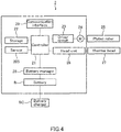
- FIG. 4 is a block diagram to represent an internal configuration of the printer 2.
- the printer 2 includes: for example, a controller 21; a storage 22; a driver circuit 23; the motor 24 which is mechanically connected to the platen roller 25; a head unit 26 that drives the thermal head 27; a battery manager 28; a communication interface (I/F) 29; the sensor 205; and the battery B.
- the communication interface 29 (exemplary communication part and exemplary first communication part) employs a communication circuit to communicate with an outside device.
- the battery manager 28 may be integrated into the battery B. Note that the head unit 26 and the thermal head 27 function as a printing part.
- the controller 21 is comprised of a microcomputer and memories (namely, a random access memory (RAM) and a read-only memory (ROM)) to control operations of the printer 2.
- the microcomputer loads a firmware from the ROM when the printer 2 is powered on, and executes the firmware.
- Execution of the firmware causes the controller 21 to function as print instruction means for instructing to print predetermined information on a business form.
- Execution of the firmware causes the controller 21 to function as determining means for determining a number of business forms on which the printer can print with present remaining battery capacity of the battery B, based on information related to variation of remaining battery capacity of the battery B relative to a number of business forms that have been issued.
- the storage 22 is a storage device such as a solid state drive (SDD).
- the storage 22 may store information of print format(s) applied when information is printed on each business form, in addition to print data to be printed on each business form.
- a cumulative number of rotations of the platen roller 25 (namely, a cumulative number of platen roller rotations) is stored in the storage 22. The cumulative number of platen roller rotations is sequentially updated by the controller 21.
- the driver circuit 23 is a circuit that drives the motor 24 for controlling rotation of the platen roller 25, responsive to a feed request form the controller 21.
- the motor 24 is a stepping motor, for example.
- the feed request includes, for example, information about a feed direction (namely, a forward direction or a reverse direction) and a feed amount (a number of steps, etc.).
- the head unit 26 includes a circuit that causes current to selectively flow through each of a plurality of heating elements of the thermal head 27, based on each line data of print data transmitted from the controller 21.
- a color develops at a part of the continuous paper to which the heating elements are pushed, thereby printing information on the continuous paper CP.
- the battery manager 28 includes, for example, a voltage sensor, a current sensor, a temperature sensor, and a control circuit.
- the control circuit is configured to process detection signals from the sensors to compute and record battery status information of the battery B.
- the voltage sensor is configured to detect a voltage between terminals of the battery B.
- the temperature sensor may be attached to the battery B, or may be disposed in the vicinity of the battery B.
- the temperature sensor is configured to detect a temperature of the battery B.
- the current sensor is disposed on a line connected to one terminal of the battery B to detect current that flows in the line (namely, current that flows through the battery B ) .
- the battery manager 28 transmits the battery status information of the battery B, responsive to an instruction from the controller 21, or at a predetermined time.
- the battery status information of the battery B, which is managed by the battery manager 28, may include, but not limited to:
- the battery B can be recharged when a user connects the both terminals of the battery B in the printer 2, to a charger BC.
- the charger BC is connected to commercial power supply such as 100V AC power supply with which to charge the battery B.
- Functions that are realized by execution of the firmware in the controller 21 may include at least the following functions (i) to (iv):
- FIG. 5 shows a method for computing a number-of-forms-issuable.
- FIG. 5 shows a relation between a number of business forms that have been issued by the printer 2 and SOC (%) (namely, remaining battery capacity) of the battery B.
- SOC namely, remaining battery capacity
- a period which starts at a time t1 (referred to as “measurement start time") and ends at a time t2 (referred to as “measurement end time”) is set.
- the time t2 corresponds to one when a number-of-forms-issuable of the business forms is computed.
- the controller 21 of the printer 2 computes a decrease rate of remaining battery capacity of the battery B relative to business forms that have been issued, based on a decreased amount of the remaining battery capacity of the battery B during the period from the time t1 to the time t2, and a number of business forms that have been issued during the period. That is, the controller 21 computes a decreased amount of the remaining battery capacity of the battery B for issuing a single business form.
- SOC or a charge amount at the time t1 is CR1 and that SOC or a charge amount at the time t2 is CR2. It is also assumed that a threshold of a lower limit of the SOC of the battery B is TH1. If the SOC of the battery B decreases to the threshold TH1, then the battery B needs to be charged by the charger BC.
- the threshold TH1 may be set to be 40% to 50% in light of a long-life of the battery B, for example.
- a number of business forms that have been issued during the period from the time t1 to the time t2 may be computed in a method described below.
- a diameter D of the platen roller 25 is known.
- a number of pulses n2 that have been actually applied for printing is divided by a number of pulses n1 of the stepping motor for a single rotation of the platen roller 25, to find a number of rotations (n2/n1) of the stepping motor during a period of time in which business forms have been fed. That is, a feed amount of the business forms in printing can be found by ⁇ D*(n2/n1).
- the feed amount of business forms in printing can be computed; however, in a case of continuous issuance, a number of business forms that have been issued cannot be counted.
- the sensor 205 transmits to the controller 21, a detection signal indicating that the sensor 205 has detected the location detection mark M.
- the location detection mark M is formed with predetermined intervals on the rear face of the continuous paper CP to indicate a positon of each business form.
- a number of pulses n3 of the stepping motor for feeding a distance between adjoining location detection marks M can be detected.
- the number of pulses n2 that have been actually applied for printing is divided by n3, to enable to count the number of business forms that have been issued (n2/n3).
- a decrease rate (that is, a decrease amount of the remaining battery capacity of the battery B for issuing a signal business form) can be found.
- a decrease rate Rb of the remaining battery capacity of the battery B relative to the number of business forms that have been issued is found by the following equation (1) for example.
- a value of (CR1-CR2) corresponds to a variation of the remaining battery capacity.
- Rb CR 1 ⁇ CR 2 N n
- a number-of-forms-issuable PLn is found by the following equation (2) for example.
- the number-of-forms-issuable PLn is a number of business forms that can be issued during a period of time in which the SOC varies from CR2 at the time t2 to the threshold TH1.
- PLn CR 2 ⁇ TH 1 CR 1 ⁇ CR 2 ⁇ N n
- a time when the number-of-forms-issuable is computed is not limited.
- computation of the number-of-forms-issuable may be triggered by an input performed by a user to the printer 2 while the printer 2 is in the operation period.
- the measurement start time t1 is not limited.
- the measurement start time t1 may be a time when the printer 2 is detached from the charger BC to start the operation period of the printer 2, or may be a time when a user performs an input to the printer 2 during the operation period of the printer 2.
- the controller 21 computes a decrease rate of the SOC during the measurement period.
- the measurement period is within the operation period in which the printer 2 is not connected to the charger BC. Based on the decrease rate, the controller 21 then computes the number-of-forms-issuable of the business forms with remaining battery capacity of the battery B at the present time.
- the measurement end time may not necessarily coincide with the present time (that is, a time when the number-of-forms-issuable is computed). As long as the measurement end time in the operation period has elapsed and the decrease rate of the SOC has been computed, the number-of-forms-issuable may be able to be computed at any time after the measurement end time.
- FIG. 6 is a flowchart showing a sequence of instructions performed by the printer 2.
- the flowchart shown in FIG. 6 is mainly executed by the controller 21 of the printer 2.
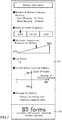
- FIG. 7 shows a print example by the printer 2.
- the controller 21 obtains battery status information of the battery B from the battery manager 28 at the measurement start time (step S10: YES, step S12), and records the obtained battery status information of the battery B and a cumulative number of platen roller rotations, in the RAM for example (step S14).
- the battery status information of the battery B includes at least information related to SOC of the battery B.
- the controller 21 determines a number of platen roller rotations for printing a single business form, based on a detection result of the sensor 205 (step S16).
- the controller 21 obtains battery status information of the battery B from the battery manager 28 at the measurement end time (step S18: YES, step S20).
- the status battery information of the battery B includes at least information related to SOC of the battery B.
- the controller 21 then computes a number-of-forms-issuable in accordance with the equation (2) described above (step S22). That is, the controller 21 reads out the SOC (corresponding to CR1 in FIG. 5 ) of the battery B and the cumulative number of platen roller rotations, which have been recorded at the step S14. Based on: the data that have been read out; the SOC (corresponding to CR2 in FIG. 5 ) of the battery B, which have been obtained at the step S20; a cumulative number of platen roller rotations at the present time; and a threshold (corresponding to TH1 in FIG. 5 ), which is a fixed parameter, the controller 21 computes the number-of-forms-issuable in accordance with the equation (2) described above.
- the controller 21 is configured to print information related to the number-of-forms-issuable (step S24).
- a print example of such information is illustrated in FIG. 7 .
- FIG. 7 shows a preferable example in which the information related to the number-of-forms-issuable is printed on a print region A2 and information of the battery B is printed on a print region A1 .
- Printed on the print region A1 in the example of FIG. 7 are pieces of information related to items including: “Number of Battery Charging”; “State of Health of Battery”; “Maximum Temperature Exposure for Battery”; “Log Factor”; “Overall Safety Level for Battery”; and “Present Comment for Battery.” Note that information for all items may not be necessarily printed on the print region A1, and that a piece of information corresponding to at least one of items may be printed on the print region A1.
- “Number of Battery Charging” is information that indicates a total number of battery charging. If a number of fast charging and a number of slow charging are separately counted, then “Number of Battery Charging” indicates each number of charging. In this case, the number of battery charging is counted every time the battery manager 28 charges the battery. Since battery deterioration proceeds as the number of battery charging increases, the number of battery charging is an indicator of battery deterioration.
- SOH State of Health of Battery
- the SOH is represented by a ratio of present battery capacity relative to initial battery capacity, or by a ratio of the present internal resistance relative to an initial internal resistance of the battery.
- one of three levels (“good”, “caution”, and “swap") is indicated by an arrow as “State of Health of Battery” based on the SOH.
- Maximum Temperature Exposure for Battery corresponds to a maximum temperature under which the battery has exposed to date.
- the battery manager 28 records a history of temperature of the battery. Based on the history of temperature of the battery, the battery manager 28 transmits data related to the maximum temperature, to the controller 21.
- Log Factor corresponds to an inverted value of a capacity recovery rate of the battery. The greater “Log Factor” indicates, the further battery deterioration proceeds.
- “Overall Safety Level for Battery” is information of the battery that is indicated on a graph.
- the number of battery charging is indicated in a horizontal axis, while the state of health (SOH) is indicated in a vertical axis.
- Message for Battery is text information for present battery status, which has been determined in accordance with certain criteria based on information of respective items described above.
- the controller 21 obtains from the battery manager 28 at the step S20, in addition to the SOC of the battery, information related to a number of battery charging, and a temperature history of the battery B, SOH, a capacity recovery rate, a resistance of the battery.
- Printing the battery information allows a user to recognize present status of the battery B.
- the controller 21 may be configured to display the information related to the number-of-forms-issuable on the display, thereby notifying a user of the information.
- the printer 2 is capable of communicating with other information terminal (as an example of "external device") having a display, such as a handy terminal, then the controller 21 may transmit the information related to the computed number-of-forms-issuable to the information terminal, and the information terminal may display the information related to the number-of-forms-issuable.
- the measurement start time and the measurement end time are not limited.
- the measurement start time and the measurement end time may be set to be a start time and an end time of the operation period of the printer 2 respectively.
- the measurement start time may correspond to a time when a user detaches the printer 2 from the charger BC after arriving for work at a delivery center and goes out with the printer 2.
- the controller 21 of the printer 2 recognizes the measurement start time by detecting disconnection between the battery B and the charger BC.
- the measurement end time may correspond to a time when the user returns to the delivery center and connects the printer 2 to the charger BC before leaving.
- the controller 21 of the printer 2 recognizes the measurement end time by detecting connection between the battery B and the charger BC.
- the user is able to recognize the number-of-forms-issuable of the printer 2 when returning to the delivery center and connecting the printer 2 to the charger BC.
- useless charging may be prevented, depending on the number-of-forms-issuable.
- the measurement start time and the measurement end time may be set to be a start time of the operation period and a time when a user performs a predetermined manipulation, respectively.
- a user perform the predetermined manipulation at a desired time while using the printer 2 outside. Then, the controller 21 of the printer 2 recognizes the measurement end time, and prints or displays a number-of-forms-issuable. Since, in this example, the user can recognize the number-of-forms-issuable at a desired time while using the printer 2 (that is, in the operation period), the user may take necessary actions. Such actions may include returning to the delivery center to replace the printer 2 or the battery when the number-of-forms-issuable is small, for example.
- a plurality of printers is connected to a server through a network, and information of each printer of the plurality of printers is centrally managed by the server. While it has been described in the first embodiment that computation of a number-of-forms-issuable is executed by the printer 2, the server, in the second embodiment, is configured to compute a number-of-forms-issuable of each printer and to notify each printer of the number-of-forms-issuable.
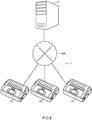
- FIG. 8 shows an overview of system configuration of an information processing system 1 according to the present embodiment.
- FIG. 9 is a block diagram to represent internal configuration of each device of the information processing system 1 according to the present embodiment.
- FIG. 10 shows an example of a printer database in the information processing system 1 according to the present embodiment.
- the information processing system 1 includes a plurality of printers 2A, 2B, 2C and a server 5.
- Each printer is capable of communicating with the server 5, through a network NW such as a local area network (LAN), a wide area network (WAN), or Internet.
- NW such as a local area network (LAN), a wide area network (WAN), or Internet.
- Each of the plurality of printers 2A, 2B, 2C has the same configuration as the printer 2 of the first embodiment.
- the printers 2A, 2B, 2C are collectively represented by "printer 2" when things common to the printers are referred to in the following description. It should be noted that the exemplary system configuration illustrated in FIG. 8 is not intended to limit printers centrally managed by the server 5, to ones having the same internal configuration.
- the server 5 includes a controller 51, a storage 52, and a communication interface (I/F) 53.
- the communication interface (communication I/F) 53 (an exemplary second communication part) has a communication circuit for communicating with the printer 2.
- the controller 51 is comprised of a microcomputer and memories (namely, a RAM and a ROM) to control operations of the server 5.
- the microcomputer loads a program from the ROM when the server 5 is powered on, and executes the program.
- the storage 52 is a storage device such as a hard disk drive (HDD).
- the storage 52 is configured to store a printer database, which is shown in FIG. 10 for example, in order to centrally manage the printers 2 connected to the server 5.
- the printer database includes information of a cumulative number of platen roller rotations and battery status information, for a printer ID that identifies each printer 2.
- the printer ID is information for identifying each printer 2, and may be a serial number, a manufacturing number, etc.
- printer IDs: A001, B002, C003 correspond to the printers 2A, 2B, 2C respectively.
- Each of the information of a cumulative number of platen roller rotations and the battery status information has the latest values and a previous values.
- the controller 51 updates the printer database such that the latest values are written in the previous record and then the received values are written in the newly latest record.
- Functions realized by execution of the program in the controller 51 includes at least the following functions (i) to (iii):
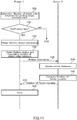
- FIG. 11 shows a sequence chart showing an exemplary behavior of the information processing system 1 according to the present embodiment.
- a sequence of instructions for the printer 2 is mainly executed by the controller 21, while a sequence of instructions for the server 5 is mainly executed by the controller 51.
- the printer 2 notifies the server 5 of printer information, at a time in the operation period in which the charger BC is not connected to the printer 2, or at a freely determined time.
- the server 5 updates the printer database based on the notified information, and transmits to the printer 2, as a response, information about a number-of-forms-issuable of the printer 2.
- the printer 2 invariably determines a number of platen roller rotations for a single business form (step S30).
- the number of platen roller rotations for a single business form should be constant, as long as a type of the paper roll R applied is not changed.
- the number of platen roller rotations for a single business form may be determined at least once during the operation period.
- the printer 2 obtains battery status information of the battery B from the battery manager 28 (step S34), and then obtains information related to a cumulative number of platen roller rotations (step S36). As information for a cumulative number of platen roller rotations is sequentially recorded in the storage 22, the controller 21 obtains the information for the cumulative number of platen roller rotations from the storage 22.
- the printer 2 transmits, to the server 5, the printer information which has been obtained at the steps S30 to S32 (step S38).
- the server 5 updates records of the printer database such that the information received at the Step S38 becomes the latest values, and a record which had been the latest before receiving the information becomes a previous record (step S40).
- the server 5 then computes a number-of-forms-issuable for the printer 2, based on records having the latest values and the previous values in the printer database, and data of the number of platen roller rotations for a single business, which have been received at the step S38.
- the computing method for the number-of-forms-issuable may be the same as described in the first embodiment.
- SOCs in the previous values and the latest values in the printer database correspond to CR1 and CR2 in the equation (2) described above, and the threshold TH1 for a lower limit of the SOC of the battery B is known by the server 5.
- a number N of platen roller rotations is found by a difference between a previous value and the latest value for the cumulative number of the platen roller rotations.
- the server 5 transmits, to the printer 2, information for the number-of-forms-issuable, which have been computed at the step S42 (step S44), and the printer 2 prints the received information for the number-of-forms-issuable (step S46).
- the printer 2 may display the information for the number-of-forms-issuable, which have been received at the step S44.
- the printer 2 may print the battery status information of the battery B, which has been obtained at the step S34, in addition to the information for the number-of-forms-issuable, as shown in FIG. 7 .
- a number-of-forms-issuable is computed, assuming that a relation between SOC of the battery and a number of the business forms that have been issued is linear; however, the present invention is not limited to this computation method.
- the relation may be defined to be nonlinear in line with actual situation, and a number-of-forms-issuable may be computed based on the nonlinear relation.
- a decrease rate in remaining battery capacity of the battery relative to a number of the business forms that have been issued is computed in each time; however, the present invention is not limited to this computation method.
- the decrease rate may be preliminarily measured, and a number-of-forms-issuable may be computed based on the measured decreased rate as a fixed value.
Landscapes
- Engineering & Computer Science (AREA)
- Theoretical Computer Science (AREA)
- Human Computer Interaction (AREA)
- Physics & Mathematics (AREA)
- General Engineering & Computer Science (AREA)
- General Physics & Mathematics (AREA)
- Accessory Devices And Overall Control Thereof (AREA)
- Printers Characterized By Their Purpose (AREA)
- Charge And Discharge Circuits For Batteries Or The Like (AREA)
- Electronic Switches (AREA)
Abstract
Description
- A present disclosure relates to a printer, a program, and an information processing system.
- In recent years, a rechargeable battery (also referred to as a secondary battery) such as a lithium-ion battery has been applied to a relatively small printer (see
Japanese Laid-open patent publication 2010-58292 - While a user brings outside a printer having a rechargeable battery and uses the printer outside, power of the battery is consumed as the printer issues print media such as business forms. Consequently, the user may have a worry about print quality deterioration of the print media or incapability of issuing a print medium due to too low remaining battery capacity.
- In view of the above, the present invention aims to preliminarily notify a user of a number of print media on which a printer equipped with a rechargeable battery is able to print.
- An embodiment according to the present invention is a printer for issuing a print medium, comprising: a rechargeable battery configured to supply power to the printer; a printing part configured to print information on the print medium; a controller configured to determine a number of print media on which the printing part can print with present remaining battery capacity of the battery, based on information related to variation of remaining battery capacity of the battery relative to a number of print media that have been issued.
- The embodiment according to the present invention is capable of preliminarily notifying a user of a number of print media on which a printer equipped with a rechargeable battery is able to print.
-
-
FIG. 1 is a perspective view of a printer with its cover closed according to a first embodiment. -
FIG. 2 is a perspective view of the printer with its cover opened according to the first embodiment. -
FIG. 3 is a partial sectional view of the printer according to the first embodiment to show a feeding path. -
FIG. 4 is a block diagram to represent an internal configuration of the printer according to the first embodiment. -
FIG. 5 shows a method for computing a number-of-forms-issuable. -
FIG. 6 is a flowchart of instructions performed by the printer according to the first embodiment. -
FIG. 7 shows a print example by the printer according to the first embodiment. -
FIG. 8 shows an overview of system configuration of an information processing system according to a second embodiment. -
FIG. 9 is a block diagram to represent internal configuration of each device of the information processing system according to the second embodiment. -
FIG. 10 shows an example of a printer database in the information processing system according to the second embodiment. -
FIG. 11 shows a sequence chart showing an exemplary behavior of the information processing system according to the second embodiment. - The present invention relates to a
Japanese patent application No. 2018-244793 filed on December 27, 2018 - In the following description, "remaining battery capacity" has substantially the same meaning as level of charge or state of charge (SOC). Remaining battery capacity indicates 100% when a battery is fully charged, and 0% when the battery is fully discharged.
- "Information related to variation of remaining battery capacity of a battery relative to a number of print media that have been issued" may be, for example, information related to variation of remaining battery capacity varied or decreased by issuing a predetermined number (one or ten, for example) of print media, or may be information related to a decrease rate in remaining battery capacity of the battery relative to a number of print media that have been issued.
- First, overview of configuration of a printer according to the present embodiment will be described with reference to
FIGS. 1 to 3 .FIG. 1 is a perspective view of aprinter 2 with its cover closed.FIG. 2 is a perspective view of theprinter 2 with its cover opened.FIG. 3 is a partial sectional view of theprinter 2 to show a feeding path in theprinter 2. - The
printer 2 is, for example, a mobile small-sized printer and operates with power of a battery. The battery is a secondary battery such as a lithium-ion battery. - As illustrated in
FIG. 1 , theprinter 2 is a mobile printer that has a flat cuboid shape, for example. A user may use theprinter 2 with transverse posture, or may use theprinter 2 with a belt hook (not illustrated) or a shoulder belt (not illustrated) equipped. Non-limiting applications of theprinter 2 includes a case in which a delivery person of a package uses theprinter 2 to issue, at a receiver's address, a printed business form such as a receipt or a delivery absence notice. - A period in which the
printer 2 is activated is assumed to include an operation period and a non-operation period. The operation period is a period in which a user carries theprinter 2, which has been detached from a charger, and intermittently issues a business form as a print medium. The non-operation period is a period in which a business is not issued. In the case described above for example, the "operation period" corresponds to a period of time beginning from a time when a delivery person detaches theprinter 2 from a charger after arriving for work at a delivery center and starts delivery of packages with theprinter 2, and ending at a time when the delivery person returns to the delivery center after completing the delivery of the packages and connects theprinter 2 to the charger. The "non-operation period" corresponds to a period of time in which theprinter 2 is connected to the charger. That is, the "non-operation period" is a period other than the operation period. The battery of theprinter 2 is charged during the non-operation period. - The
exemplary printer 2 shown inFIGS. 1 and2 has abody case 201 and acover 202. As illustrated inFIG 2 , an end of thecover 202 is pivotally supported to thebody case 201 with a hinge. The end of thecover 202 is structured so that thecover 202 is swingable in a direction away from and in a direction toward thebody case 201. Pushing abutton 204 causes thecover 202 to open, and a container SP is opened. The container SP is space in which a paper roll R, which is illustrated inFIG. 2 , for example, is contained. - The paper roll R is made by winding a belt-shaped long strip of continuous paper CP into a roll shape. The paper roll R is stored (loaded) in the container SP in a drop-in manner when the
cover 202 is open. In an example of the present embodiment, the paper roll R does not have a core, and is therefore made by winding the belt-shaped continuous paper CP so that a cylindrical hollow part with a predetermined diameter is formed. - A heat-sensitive color developing layer is formed on a print face of the continuous paper CP. The layer's color develops when temperature of the layer reaches a predetermined temperature range.
- A location detection marks M are provided on the rear side of the print face of the continuous paper CP, in a longitudinal direction, to indicate a print reference position of each business form. The location detection marks M are rectangular marks printed in black on the rear side of the print face of the continuous paper CP, and are formed with predetermined intervals.
- A
battery cover 203 is attached to one side of thebody case 201 in a openable and closable manner. Thebattery cover 203 opens or closes a batter housing in which a battery B (illustrated inFIG. 4 ) is contained. - A
platen roller 25 is pivotally supported at the front end of thecover 202 so that theplaten roller 25 can rotate in a forward direction and a reverse direction. Theplaten roller 25 is a feed roller configured to feed the continuous paper CP extracted from the paper roll R. Theplaten roller 25 extends in the width direction of the continuous paper CP. Theplaten roller 25 is formed to extend along a width direction of the continuous paper CP. Theplaten roller 25 is driven by a motor 24 (illustrated inFIG. 4 ) via a gear, etc. - As illustrated in
FIG. 2 , asensor 205 is disposed on a portion of thecover 202 in the vicinity of theplaten roller 25. More specifically, thesensor 205 is disposed on a surface of thecover 202 facing a feeding path when thecover 202 is closed. Thesensor 205 is configured to detect a reference position of the business form (namely, the location detection mark M of the continuous paper CP). Thesensor 205 is a reflective type optical sensor. -
FIG. 3 shows a feeding path in a bold line when the paper roll R is contained in the container SP. InFIG. 3 , the paper roll R is made by winding the continuous paper CP counterclockwise. - As shown in
FIG. 3 , when thecover 202 is closed, a portion of thecover 202 and a portion of afeed guide 207 are opposed with a slight gap. The gap forms a feeding path of the continuous paper CP, which is extracted from the paper roll R, directing from the container SP toward theplaten roller 25. Note that thesensor 205, which is disposed at thecover 202, is opposed to the feeding path, in order to detect the location detection marks M of the continuous paper CP that passes through the feeding path. - With the continuous paper CP pinched between the
platen roller 25 and athermal head 27, theprinter 2 prints on the respective business forms. Printing on the respective business forms is timed based on detection of the location detection marks M by thesensor 205 for example. - Next, an internal configuration of the
printer 2 will be described with reference toFIG. 4. FIG. 4 is a block diagram to represent an internal configuration of theprinter 2. - As shown in
FIG. 4 , theprinter 2 includes: for example, acontroller 21; astorage 22; adriver circuit 23; themotor 24 which is mechanically connected to theplaten roller 25; ahead unit 26 that drives thethermal head 27; abattery manager 28; a communication interface (I/F) 29; thesensor 205; and the battery B. The communication interface 29 (exemplary communication part and exemplary first communication part) employs a communication circuit to communicate with an outside device. - The
battery manager 28 may be integrated into the battery B. Note that thehead unit 26 and thethermal head 27 function as a printing part. - The
controller 21 is comprised of a microcomputer and memories (namely, a random access memory (RAM) and a read-only memory (ROM)) to control operations of theprinter 2. The microcomputer loads a firmware from the ROM when theprinter 2 is powered on, and executes the firmware. - Execution of the firmware causes the
controller 21 to function as print instruction means for instructing to print predetermined information on a business form. - Execution of the firmware causes the
controller 21 to function as determining means for determining a number of business forms on which the printer can print with present remaining battery capacity of the battery B, based on information related to variation of remaining battery capacity of the battery B relative to a number of business forms that have been issued. - The
storage 22 is a storage device such as a solid state drive (SDD). Thestorage 22 may store information of print format(s) applied when information is printed on each business form, in addition to print data to be printed on each business form. A cumulative number of rotations of the platen roller 25 (namely, a cumulative number of platen roller rotations) is stored in thestorage 22. The cumulative number of platen roller rotations is sequentially updated by thecontroller 21. - The
driver circuit 23 is a circuit that drives themotor 24 for controlling rotation of theplaten roller 25, responsive to a feed request form thecontroller 21. Themotor 24 is a stepping motor, for example. The feed request includes, for example, information about a feed direction (namely, a forward direction or a reverse direction) and a feed amount (a number of steps, etc.). - The
head unit 26 includes a circuit that causes current to selectively flow through each of a plurality of heating elements of thethermal head 27, based on each line data of print data transmitted from thecontroller 21. When heating elements heated by the current are pushed to the continuous paper CP fed by theplaten roller 25, a color develops at a part of the continuous paper to which the heating elements are pushed, thereby printing information on the continuous paper CP. - The
battery manager 28 includes, for example, a voltage sensor, a current sensor, a temperature sensor, and a control circuit. The control circuit is configured to process detection signals from the sensors to compute and record battery status information of the battery B. The voltage sensor is configured to detect a voltage between terminals of the battery B. The temperature sensor may be attached to the battery B, or may be disposed in the vicinity of the battery B. The temperature sensor is configured to detect a temperature of the battery B. The current sensor is disposed on a line connected to one terminal of the battery B to detect current that flows in the line (namely, current that flows through the battery B). - The
battery manager 28 transmits the battery status information of the battery B, responsive to an instruction from thecontroller 21, or at a predetermined time. - The battery status information of the battery B, which is managed by the
battery manager 28, may include, but not limited to: - a number of charging to the battery B (namely, a number of fast charging and a number of slow charging);
- temperature-exposure history of the battery B
- one of, or a combination of estimate values including state of charge (SOC), state of power (SOP), state of health (SOH; namely, indicator of battery degradation), a capacity recovery rate, and an internal resistance of the battery B
- The battery B can be recharged when a user connects the both terminals of the battery B in the
printer 2, to a charger BC. For example, the charger BC is connected to commercial power supply such as 100V AC power supply with which to charge the battery B. - Functions that are realized by execution of the firmware in the
controller 21 may include at least the following functions (i) to (iv): - (i) Obtaining battery status information of the battery B;
- (ii) Updating a cumulative number of platen roller rotations;
- (iii) Determining a number of platen roller rotations for printing a single business form; and
- (iv) Computing a number-of-forms-issuable (that is, a number of business forms on which the printer can print with remaining battery capacity of the battery B).
- Next, a principle of computing a number-of-forms-issuable with remaining battery capacity at a time in the
printer 2 according to the present embodiment, will be explained.FIG. 5 shows a method for computing a number-of-forms-issuable. -
FIG. 5 shows a relation between a number of business forms that have been issued by theprinter 2 and SOC (%) (namely, remaining battery capacity) of the battery B. As shown inFIG. 5 , as theprinter 2 issues a business form, power is consumed, thereby reducing the remaining battery capacity of the battery B in theprinter 2. Thus, a number-of-forms-issuable with the remaining battery capacity of the battery B varies (decreases) from time to time. Note thatFIG. 5 applies approximation, assuming that a relation between the number-of-forms-issuable and the SOC of the battery B is linear. - When the
printer 2 is not charged, for example, not in an operation period (the aforementioned "operation period"), a period which starts at a time t1 (referred to as "measurement start time") and ends at a time t2 (referred to as "measurement end time") is set. The time t2 corresponds to one when a number-of-forms-issuable of the business forms is computed. - The
controller 21 of theprinter 2 computes a decrease rate of remaining battery capacity of the battery B relative to business forms that have been issued, based on a decreased amount of the remaining battery capacity of the battery B during the period from the time t1 to the time t2, and a number of business forms that have been issued during the period. That is, thecontroller 21 computes a decreased amount of the remaining battery capacity of the battery B for issuing a single business form. - In
FIG. 5 , it is assumed that SOC or a charge amount at the time t1 is CR1 and that SOC or a charge amount at the time t2 is CR2. It is also assumed that a threshold of a lower limit of the SOC of the battery B is TH1. If the SOC of the battery B decreases to the threshold TH1, then the battery B needs to be charged by the charger BC. The threshold TH1 may be set to be 40% to 50% in light of a long-life of the battery B, for example. - In a case in which a stepping motor is used in the
printer 2, for example, a number of business forms that have been issued during the period from the time t1 to the time t2, may be computed in a method described below. - First, a diameter D of the
platen roller 25 is known. Next, a number of pulses n2 that have been actually applied for printing, is divided by a number of pulses n1 of the stepping motor for a single rotation of theplaten roller 25, to find a number of rotations (n2/n1) of the stepping motor during a period of time in which business forms have been fed. That is, a feed amount of the business forms in printing can be found by πD*(n2/n1). - The feed amount of business forms in printing can be computed; however, in a case of continuous issuance, a number of business forms that have been issued cannot be counted.
- In view of the above, the
sensor 205 transmits to thecontroller 21, a detection signal indicating that thesensor 205 has detected the location detection mark M. The location detection mark M is formed with predetermined intervals on the rear face of the continuous paper CP to indicate a positon of each business form. Incidentally, a number of pulses n3 of the stepping motor for feeding a distance between adjoining location detection marks M, can be detected. Thus, the number of pulses n2 that have been actually applied for printing, is divided by n3, to enable to count the number of business forms that have been issued (n2/n3). - Base on the number of business forms that have been issued during the period from the time t1 to the time t2, and the SOC or the charge amount, a decrease rate (or amount) (that is, a decrease amount of the remaining battery capacity of the battery B for issuing a signal business form) can be found.
- Note that, as the diameter of the
platen roller 25 decreases as it wears in use, a feed amount of the continuous paper CP by a single pulse of the stepping motor also decreases. Thus, the number of business forms that have been issued, computed later in life of the platen roller, will slightly deviate from that computed at the start of use of the platen roller. Nevertheless, such deviation can be limited by processing broken numbers, such as rounding off fractions. - Referring to
FIG. 5 , a decrease rate Rb of the remaining battery capacity of the battery B relative to the number of business forms that have been issued, is found by the following equation (1) for example. In the equation (1), a value of (CR1-CR2) corresponds to a variation of the remaining battery capacity.
- A number-of-forms-issuable PLn is found by the following equation (2) for example. The number-of-forms-issuable PLn is a number of business forms that can be issued during a period of time in which the SOC varies from CR2 at the time t2 to the threshold TH1.

- As described above, a number-of-forms-issuable of the business forms can be computed.
- It should be noted that, a time when the number-of-forms-issuable is computed, is not limited. For example, computation of the number-of-forms-issuable may be triggered by an input performed by a user to the
printer 2 while theprinter 2 is in the operation period. - Additionally, the measurement start time t1 is not limited. For example, the measurement start time t1 may be a time when the
printer 2 is detached from the charger BC to start the operation period of theprinter 2, or may be a time when a user performs an input to theprinter 2 during the operation period of theprinter 2. - As described above, based on a variation of the SOC of the battery B during a measurement period from the measurement start time to the measurement end time, the
controller 21 computes a decrease rate of the SOC during the measurement period. The measurement period is within the operation period in which theprinter 2 is not connected to the charger BC. Based on the decrease rate, thecontroller 21 then computes the number-of-forms-issuable of the business forms with remaining battery capacity of the battery B at the present time. - Note that the measurement end time may not necessarily coincide with the present time (that is, a time when the number-of-forms-issuable is computed). As long as the measurement end time in the operation period has elapsed and the decrease rate of the SOC has been computed, the number-of-forms-issuable may be able to be computed at any time after the measurement end time.
- Next, an exemplary behavior of the
printer 2 according to the present embodiment will be described with reference toFIGS. 6 and7 . -
FIG. 6 is a flowchart showing a sequence of instructions performed by theprinter 2. The flowchart shown inFIG. 6 is mainly executed by thecontroller 21 of theprinter 2.FIG. 7 shows a print example by theprinter 2. - In the flowchart of
FIG. 6 , thecontroller 21 obtains battery status information of the battery B from thebattery manager 28 at the measurement start time (step S10: YES, step S12), and records the obtained battery status information of the battery B and a cumulative number of platen roller rotations, in the RAM for example (step S14). The battery status information of the battery B includes at least information related to SOC of the battery B. - The
controller 21 then determines a number of platen roller rotations for printing a single business form, based on a detection result of the sensor 205 (step S16). - The
controller 21 obtains battery status information of the battery B from thebattery manager 28 at the measurement end time (step S18: YES, step S20). The status battery information of the battery B includes at least information related to SOC of the battery B. - The
controller 21 then computes a number-of-forms-issuable in accordance with the equation (2) described above (step S22). That is, thecontroller 21 reads out the SOC (corresponding to CR1 inFIG. 5 ) of the battery B and the cumulative number of platen roller rotations, which have been recorded at the step S14. Based on: the data that have been read out; the SOC (corresponding to CR2 inFIG. 5 ) of the battery B, which have been obtained at the step S20; a cumulative number of platen roller rotations at the present time; and a threshold (corresponding to TH1 inFIG. 5 ), which is a fixed parameter, thecontroller 21 computes the number-of-forms-issuable in accordance with the equation (2) described above. - According to an example of the present embodiment, the
controller 21 is configured to print information related to the number-of-forms-issuable (step S24). A print example of such information is illustrated inFIG. 7 . -
FIG. 7 shows a preferable example in which the information related to the number-of-forms-issuable is printed on a print region A2 and information of the battery B is printed on a print region A1. - In the example of
FIG. 7 , "85 forms", which is printed on the print region A2, is a value of the number-of-forms-issuable, which has been computed at the step S22. - Printed on the print region A1 in the example of
FIG. 7 are pieces of information related to items including: "Number of Battery Charging"; "State of Health of Battery"; "Maximum Temperature Exposure for Battery"; "Log Factor"; "Overall Safety Level for Battery"; and "Present Comment for Battery." Note that information for all items may not be necessarily printed on the print region A1, and that a piece of information corresponding to at least one of items may be printed on the print region A1. - "Number of Battery Charging" is information that indicates a total number of battery charging. If a number of fast charging and a number of slow charging are separately counted, then "Number of Battery Charging" indicates each number of charging. In this case, the number of battery charging is counted every time the
battery manager 28 charges the battery. Since battery deterioration proceeds as the number of battery charging increases, the number of battery charging is an indicator of battery deterioration. - "State of Health of Battery", which corresponds to SOH of the battery, is a factor indicating health condition (or status of health) of the battery. The SOH is represented by a ratio of present battery capacity relative to initial battery capacity, or by a ratio of the present internal resistance relative to an initial internal resistance of the battery. In
FIG. 7 , one of three levels ("good", "caution", and "swap") is indicated by an arrow as "State of Health of Battery" based on the SOH. - "Maximum Temperature Exposure for Battery", indicated by an arrow, corresponds to a maximum temperature under which the battery has exposed to date. The
battery manager 28 records a history of temperature of the battery. Based on the history of temperature of the battery, thebattery manager 28 transmits data related to the maximum temperature, to thecontroller 21. - "Log Factor" corresponds to an inverted value of a capacity recovery rate of the battery. The greater "Log Factor" indicates, the further battery deterioration proceeds.
- "Overall Safety Level for Battery" is information of the battery that is indicated on a graph. In the graph, the number of battery charging is indicated in a horizontal axis, while the state of health (SOH) is indicated in a vertical axis.
- "Message for Battery" is text information for present battery status, which has been determined in accordance with certain criteria based on information of respective items described above.
- In order to print the information included in the print region A1 of
FIG. 7 at the step S24, thecontroller 21 obtains from thebattery manager 28 at the step S20, in addition to the SOC of the battery, information related to a number of battery charging, and a temperature history of the battery B, SOH, a capacity recovery rate, a resistance of the battery. - Printing the battery information, as shown in the print region A1 of
FIG. 7 as an example, allows a user to recognize present status of the battery B. - With reference to
FIGS. 6 and7 , a case has been described that information related to the number-of-forms-issuable is printed; however, the present invention is not limited to this case. If theprinter 2 is equipped with a display, then thecontroller 21 may be configured to display the information related to the number-of-forms-issuable on the display, thereby notifying a user of the information. - If the
printer 2 is capable of communicating with other information terminal (as an example of "external device") having a display, such as a handy terminal, then thecontroller 21 may transmit the information related to the computed number-of-forms-issuable to the information terminal, and the information terminal may display the information related to the number-of-forms-issuable. - As described above, the measurement start time and the measurement end time are not limited. For example, as shown in
FIG. 6 , the measurement start time and the measurement end time may be set to be a start time and an end time of the operation period of theprinter 2 respectively. - For example, the measurement start time may correspond to a time when a user detaches the
printer 2 from the charger BC after arriving for work at a delivery center and goes out with theprinter 2. In this case, thecontroller 21 of theprinter 2 recognizes the measurement start time by detecting disconnection between the battery B and the charger BC. The measurement end time may correspond to a time when the user returns to the delivery center and connects theprinter 2 to the charger BC before leaving. In this case, thecontroller 21 of theprinter 2 recognizes the measurement end time by detecting connection between the battery B and the charger BC. - In this example, the user is able to recognize the number-of-forms-issuable of the
printer 2 when returning to the delivery center and connecting theprinter 2 to the charger BC. Thus, useless charging may be prevented, depending on the number-of-forms-issuable. - In other example, the measurement start time and the measurement end time may be set to be a start time of the operation period and a time when a user performs a predetermined manipulation, respectively.
- For example, a user perform the predetermined manipulation at a desired time while using the
printer 2 outside. Then, thecontroller 21 of theprinter 2 recognizes the measurement end time, and prints or displays a number-of-forms-issuable. Since, in this example, the user can recognize the number-of-forms-issuable at a desired time while using the printer 2 (that is, in the operation period), the user may take necessary actions. Such actions may include returning to the delivery center to replace theprinter 2 or the battery when the number-of-forms-issuable is small, for example. - Next, an information processing system of the second embodiment according to the present invention will be described with reference to
FIGS. 8 to 11 . - In the information processing system of the second embodiment, a plurality of printers is connected to a server through a network, and information of each printer of the plurality of printers is centrally managed by the server. While it has been described in the first embodiment that computation of a number-of-forms-issuable is executed by the
printer 2, the server, in the second embodiment, is configured to compute a number-of-forms-issuable of each printer and to notify each printer of the number-of-forms-issuable. -
FIG. 8 shows an overview of system configuration of aninformation processing system 1 according to the present embodiment.FIG. 9 is a block diagram to represent internal configuration of each device of theinformation processing system 1 according to the present embodiment.FIG. 10 shows an example of a printer database in theinformation processing system 1 according to the present embodiment. - As shown in
FIG. 8 , theinformation processing system 1 according to the present embodiment includes a plurality ofprinters server 5. Each printer is capable of communicating with theserver 5, through a network NW such as a local area network (LAN), a wide area network (WAN), or Internet. Each of the plurality ofprinters printer 2 of the first embodiment. Theprinters printer 2" when things common to the printers are referred to in the following description. It should be noted that the exemplary system configuration illustrated inFIG. 8 is not intended to limit printers centrally managed by theserver 5, to ones having the same internal configuration. - As the internal configuration of the
printer 2 inFIG. 9 is the same as that shown inFIG. 4 , redundant explanation for the internal configuration will be omitted here. - As shown in
FIG. 9 , theserver 5 includes acontroller 51, astorage 52, and a communication interface (I/F) 53. The communication interface (communication I/F) 53 (an exemplary second communication part) has a communication circuit for communicating with theprinter 2. - The
controller 51 is comprised of a microcomputer and memories (namely, a RAM and a ROM) to control operations of theserver 5. The microcomputer loads a program from the ROM when theserver 5 is powered on, and executes the program. - The
storage 52 is a storage device such as a hard disk drive (HDD). Thestorage 52 is configured to store a printer database, which is shown inFIG. 10 for example, in order to centrally manage theprinters 2 connected to theserver 5. - As shown in
FIG. 10 , the printer database includes information of a cumulative number of platen roller rotations and battery status information, for a printer ID that identifies eachprinter 2. - The printer ID is information for identifying each
printer 2, and may be a serial number, a manufacturing number, etc. In an example of the present embodiment, printer IDs: A001, B002, C003 correspond to theprinters - Each of the information of a cumulative number of platen roller rotations and the battery status information has the latest values and a previous values. When receiving, from each
printer 2, a value of information of a cumulative number of rotations of the platen roller and a value of the battery status, thecontroller 51 updates the printer database such that the latest values are written in the previous record and then the received values are written in the newly latest record. - Functions realized by execution of the program in the
controller 51 includes at least the following functions (i) to (iii): - (i) Obtaining, from each
printer 2, battery status information of the battery B, information related to a cumulative number of platen roller rotations, and information related to a number of platen roller rotations for a single business form (which are collectively referred to as "printer information"); - (ii) Updating the printer database; and
- (iii) Computing a number-of-forms-issuable of business forms with remaining battery capacity of the battery B of each
printer 2, and notifying eachprinter 2 of the number-of-forms-issuable. - Next, an exemplary behavior of the
information processing system 1 according to the present embodiment will be described with reference toFIG. 11. FIG. 11 shows a sequence chart showing an exemplary behavior of theinformation processing system 1 according to the present embodiment. InFIG. 11 , a sequence of instructions for theprinter 2 is mainly executed by thecontroller 21, while a sequence of instructions for theserver 5 is mainly executed by thecontroller 51. - According to the example shown in
FIG. 11 , theprinter 2 notifies theserver 5 of printer information, at a time in the operation period in which the charger BC is not connected to theprinter 2, or at a freely determined time. Theserver 5 updates the printer database based on the notified information, and transmits to theprinter 2, as a response, information about a number-of-forms-issuable of theprinter 2. - In
FIG. 11 , theprinter 2 invariably determines a number of platen roller rotations for a single business form (step S30). The number of platen roller rotations for a single business form should be constant, as long as a type of the paper roll R applied is not changed. Thus, the number of platen roller rotations for a single business form may be determined at least once during the operation period. - At a time when the
printer 2 notifies theserver 5 of printer information (step S32: YES), theprinter 2 obtains battery status information of the battery B from the battery manager 28 (step S34), and then obtains information related to a cumulative number of platen roller rotations (step S36). As information for a cumulative number of platen roller rotations is sequentially recorded in thestorage 22, thecontroller 21 obtains the information for the cumulative number of platen roller rotations from thestorage 22. - The
printer 2 transmits, to theserver 5, the printer information which has been obtained at the steps S30 to S32 (step S38). - The
server 5 updates records of the printer database such that the information received at the Step S38 becomes the latest values, and a record which had been the latest before receiving the information becomes a previous record (step S40). Theserver 5 then computes a number-of-forms-issuable for theprinter 2, based on records having the latest values and the previous values in the printer database, and data of the number of platen roller rotations for a single business, which have been received at the step S38. - The computing method for the number-of-forms-issuable may be the same as described in the first embodiment. Note that, in the present embodiment, SOCs in the previous values and the latest values in the printer database correspond to CR1 and CR2 in the equation (2) described above, and the threshold TH1 for a lower limit of the SOC of the battery B is known by the
server 5. A number N of platen roller rotations is found by a difference between a previous value and the latest value for the cumulative number of the platen roller rotations. - The
server 5 transmits, to theprinter 2, information for the number-of-forms-issuable, which have been computed at the step S42 (step S44), and theprinter 2 prints the received information for the number-of-forms-issuable (step S46). Note that, when equipped with a display part, theprinter 2 may display the information for the number-of-forms-issuable, which have been received at the step S44. - In the step S46, the
printer 2 may print the battery status information of the battery B, which has been obtained at the step S34, in addition to the information for the number-of-forms-issuable, as shown inFIG. 7 . - The embodiments of the present invention have been described in details. However, scope of the present invention is not limited to the aforementioned embodiments described above. The aforementioned embodiments may be improved or modified in a variety of ways to such an extent that does not depart from the spirit of the present invention.
- For example, it has been described in the first embodiment that, a number-of-forms-issuable is computed, assuming that a relation between SOC of the battery and a number of the business forms that have been issued is linear; however, the present invention is not limited to this computation method. The relation may be defined to be nonlinear in line with actual situation, and a number-of-forms-issuable may be computed based on the nonlinear relation.
- In the aforementioned embodiments, it has been described that, a decrease rate in remaining battery capacity of the battery relative to a number of the business forms that have been issued, is computed in each time; however, the present invention is not limited to this computation method. The decrease rate may be preliminarily measured, and a number-of-forms-issuable may be computed based on the measured decreased rate as a fixed value.
Claims (8)
- A printer for issuing a print medium, comprising:a rechargeable battery configured to supply power to the printer;a printing part configured to print information on the print medium;a controller configured to determine a number of print media on which the printing part can print with present remaining battery capacity of the battery, based on information related to variation of remaining battery capacity of the battery relative to a number of print media that have been issued.
- The printer according to claim 1, wherein the controller computes a decrease rate of remaining battery capacity of the battery, based on a number of print media that have been issued during an operating period, and variation of the remaining battery capacity of the battery during the operating period.
- The printer according to claim 1 or 2, wherein the printing part is configured to print information related to the number of print media determined by the controller, on the print medium.
- The printer according to any one of claims 1 to 3, further comprising a display part configured to display information related to the number of print media determined by the controller.
- The printer according to any one of claims 1 to 4, further comprising a communication part configured to transmit to an outside device, information related to the number of print media determined by the controller.
- The printer according to any one of claims 1 to 5,wherein the controller is configured to obtain from the battery at least one piece of information including:information related to a number of charging to the battery;information related to a capacity recovery rate of the battery;information related to a maximum temperature of the battery to date; andinformation related to the number of print media, andwherein the printing part is configured to print the at least one piece of information obtained by the controller, on the print medium.
- A program executed in a printer that operates with power from a rechargeable battery and issues a print medium, the program being configured to cause a computer to function to:instruct to print information on the print medium, anddetermine a number of print media on which the printer can print with present remaining battery capacity of the battery, based on information related to variation of remaining battery capacity of the battery relative to a number of print media that have been issued.
- An information processing system including a server and a printer, the printer being capable of communicating with the server and issuing a print medium,wherein the printer comprises:a rechargeable battery configured to supply power to the printer;a printing part configured to print information on the print medium; anda first communication part configured to transmit to the server, information related to present remaining battery capacity of the battery and information related to variation of remaining battery capacity of the battery relative to a number of print media that have been issued, andwherein the server comprises:a controller configured to determine, based on the information transmitted, a number of print media on which the printing part can print with the present remaining battery capacity of the battery; anda second communication part configured to transmit to the printer, information related to the number of print media determined by the controller.
Applications Claiming Priority (2)
| Application Number | Priority Date | Filing Date | Title |
|---|---|---|---|
| JP2018244793A JP7492313B2 (en) | 2018-12-27 | 2018-12-27 | Printer, program, and information processing system |
| PCT/JP2019/045906 WO2020137295A1 (en) | 2018-12-27 | 2019-11-25 | Printer, program, and information processing system |
Publications (3)
| Publication Number | Publication Date |
|---|---|
| EP3904106A1 true EP3904106A1 (en) | 2021-11-03 |
| EP3904106A4 EP3904106A4 (en) | 2022-02-23 |
| EP3904106B1 EP3904106B1 (en) | 2024-07-31 |
Family
ID=71126578
Family Applications (1)
| Application Number | Title | Priority Date | Filing Date |
|---|---|---|---|
| EP19901760.9A Active EP3904106B1 (en) | 2018-12-27 | 2019-11-25 | Printer, program, and information processing system |
Country Status (4)
| Country | Link |
|---|---|
| US (1) | US11698761B2 (en) |
| EP (1) | EP3904106B1 (en) |
| JP (1) | JP7492313B2 (en) |
| WO (1) | WO2020137295A1 (en) |
Families Citing this family (2)
| Publication number | Priority date | Publication date | Assignee | Title |
|---|---|---|---|---|
| JP7664713B2 (en) * | 2021-02-26 | 2025-04-18 | サトーホールディングス株式会社 | Printers, printing systems, programs |
| JP2023160097A (en) * | 2022-04-21 | 2023-11-02 | キヤノン株式会社 | Printing device, its control method, and program |
Family Cites Families (20)
| Publication number | Priority date | Publication date | Assignee | Title |
|---|---|---|---|---|
| JPH10207585A (en) * | 1997-01-27 | 1998-08-07 | Tec Corp | Information communication system utilizing portable electronic equipment and the portable electronic equipment |
| JPH11339771A (en) * | 1998-05-22 | 1999-12-10 | Fuji Photo Film Co Ltd | Nonaqueous secondary battery |
| JP2002137506A (en) * | 2000-08-21 | 2002-05-14 | Olympus Optical Co Ltd | Printer |
| JP2004195806A (en) | 2002-12-18 | 2004-07-15 | Canon Inc | Battery Level Display Method for Portable Printing Equipment |
| JP2005343084A (en) * | 2004-06-04 | 2005-12-15 | Canon Inc | Image output apparatus and control method thereof |
| US7443529B2 (en) * | 2004-07-07 | 2008-10-28 | Sharp Laboratories Of America, Inc. | Volume of work estimating for combined processing and unprocessed imaging jobs |
| US7540581B2 (en) * | 2005-01-06 | 2009-06-02 | Seiko Epson Corporation | Print control method |
| JP4898488B2 (en) * | 2006-03-29 | 2012-03-14 | キヤノン株式会社 | Printing system, printing apparatus, control method thereof, program, and storage medium |
| JP2007283604A (en) * | 2006-04-14 | 2007-11-01 | Sharp Corp | Printing device |
| JP5361291B2 (en) | 2008-09-01 | 2013-12-04 | 富士通コンポーネント株式会社 | Printing method of thermal printer |
| JP2011076562A (en) * | 2009-10-02 | 2011-04-14 | Mitsumi Electric Co Ltd | Mobile device, notifying method, and notification program |
| JP2011198134A (en) * | 2010-03-19 | 2011-10-06 | Seiko Instruments Inc | Printing system, printer, and printer management device |
| JP5522594B2 (en) * | 2010-05-27 | 2014-06-18 | ブラザー工業株式会社 | Printing control device, printing system |
| JP5510234B2 (en) * | 2010-09-16 | 2014-06-04 | 株式会社リコー | Information processing apparatus and information processing program |
| GB201018303D0 (en) | 2010-10-29 | 2010-12-15 | Dymo Nv | Printer |
| JP2013203012A (en) | 2012-03-29 | 2013-10-07 | Toshiba Tec Corp | Label printer, program of label printer, and method of displaying number of printing sheets of label printer |
| JP2014168939A (en) | 2013-03-05 | 2014-09-18 | Ricoh Co Ltd | Image formation device |
| JP6314453B2 (en) * | 2013-12-03 | 2018-04-25 | 株式会社リコー | Image processing apparatus and program |
| JP2016147710A (en) | 2015-02-09 | 2016-08-18 | 株式会社イシダ | Label printer |
| US10261564B1 (en) * | 2015-02-25 | 2019-04-16 | Amazon Technologies, Inc. | Goal oriented device configuration |
-
2018
- 2018-12-27 JP JP2018244793A patent/JP7492313B2/en active Active
-
2019
- 2019-11-25 US US17/414,539 patent/US11698761B2/en active Active
- 2019-11-25 EP EP19901760.9A patent/EP3904106B1/en active Active
- 2019-11-25 WO PCT/JP2019/045906 patent/WO2020137295A1/en not_active Ceased
Also Published As
| Publication number | Publication date |
|---|---|
| EP3904106A4 (en) | 2022-02-23 |
| JP2020104380A (en) | 2020-07-09 |
| EP3904106B1 (en) | 2024-07-31 |
| US20220075568A1 (en) | 2022-03-10 |
| US11698761B2 (en) | 2023-07-11 |
| JP7492313B2 (en) | 2024-05-29 |
| WO2020137295A1 (en) | 2020-07-02 |
Similar Documents
| Publication | Publication Date | Title |
|---|---|---|
| US6863364B2 (en) | Systems and methods for estimating pages remaining for a printing device component | |
| US7245839B2 (en) | Printer | |
| EP3904106B1 (en) | Printer, program, and information processing system | |
| EP2619638A1 (en) | Printer with battery charged via usb port | |
| CN101976025A (en) | Toner cartridge | |
| CN1333321C (en) | Electronic apparatus that determines a characteristic of a battery | |
| US11092920B2 (en) | Image forming apparatus | |
| JP7159040B2 (en) | Printers, Information Processing Systems, and Programs | |
| JP2003302879A (en) | Developing member storage cartridge and image forming apparatus | |
| JP6826320B2 (en) | Battery charging device, recording device | |
| CN116568518B (en) | Printers, printing systems, storage media | |
| JP2013203012A (en) | Label printer, program of label printer, and method of displaying number of printing sheets of label printer | |
| JP5445434B2 (en) | Printing device | |
| JP4621135B2 (en) | Secondary battery powered printer | |
| JP5445433B2 (en) | Printing device | |
| JP2005065429A5 (en) | ||
| KR100476959B1 (en) | Method for alarming replacement-time of articles for consumption in the printer | |
| JP3873530B2 (en) | Battery-powered electronic device and program recording medium thereof | |
| EP2894037B1 (en) | Method of controlling printer and printer | |
| JP2020135583A (en) | Printing management system and printing management program | |
| JP6166626B2 (en) | Printer and printing method thereof | |
| CN102520599A (en) | Image forming apparatus and image forming system | |
| KR100645963B1 (en) | An image forming apparatus and method using a configuration unit having a CRMB memory | |
| JPH05246070A (en) | Thermal line printer | |
| JP2014091309A (en) | Printing apparatus and method for controlling the same |
Legal Events
| Date | Code | Title | Description |
|---|---|---|---|
| STAA | Information on the status of an ep patent application or granted ep patent |
Free format text: STATUS: THE INTERNATIONAL PUBLICATION HAS BEEN MADE |
|
| PUAI | Public reference made under article 153(3) epc to a published international application that has entered the european phase |
Free format text: ORIGINAL CODE: 0009012 |
|
| STAA | Information on the status of an ep patent application or granted ep patent |
Free format text: STATUS: REQUEST FOR EXAMINATION WAS MADE |
|
| 17P | Request for examination filed |
Effective date: 20210616 |
|
| AK | Designated contracting states |
Kind code of ref document: A1 Designated state(s): AL AT BE BG CH CY CZ DE DK EE ES FI FR GB GR HR HU IE IS IT LI LT LU LV MC MK MT NL NO PL PT RO RS SE SI SK SM TR |
|
| A4 | Supplementary search report drawn up and despatched |
Effective date: 20220124 |
|
| RIC1 | Information provided on ipc code assigned before grant |
Ipc: B41J 29/393 20060101ALI20220118BHEP Ipc: B41J 11/46 20060101ALI20220118BHEP Ipc: G06F 3/12 20060101ALI20220118BHEP Ipc: B41J 29/46 20060101ALI20220118BHEP Ipc: B41J 29/38 20060101ALI20220118BHEP Ipc: B41J 3/36 20060101ALI20220118BHEP Ipc: B41J 2/32 20060101AFI20220118BHEP |
|
| DAV | Request for validation of the european patent (deleted) | ||
| DAX | Request for extension of the european patent (deleted) | ||
| GRAP | Despatch of communication of intention to grant a patent |
Free format text: ORIGINAL CODE: EPIDOSNIGR1 |
|
| STAA | Information on the status of an ep patent application or granted ep patent |
Free format text: STATUS: GRANT OF PATENT IS INTENDED |
|
| INTG | Intention to grant announced |
Effective date: 20240318 |
|
| GRAS | Grant fee paid |
Free format text: ORIGINAL CODE: EPIDOSNIGR3 |
|
| P01 | Opt-out of the competence of the unified patent court (upc) registered |
Effective date: 20240517 |
|
| GRAA | (expected) grant |
Free format text: ORIGINAL CODE: 0009210 |
|
| STAA | Information on the status of an ep patent application or granted ep patent |
Free format text: STATUS: THE PATENT HAS BEEN GRANTED |
|
| AK | Designated contracting states |
Kind code of ref document: B1 Designated state(s): AL AT BE BG CH CY CZ DE DK EE ES FI FR GB GR HR HU IE IS IT LI LT LU LV MC MK MT NL NO PL PT RO RS SE SI SK SM TR |
|
| REG | Reference to a national code |
Ref country code: CH Ref legal event code: EP Ref country code: GB Ref legal event code: FG4D |
|
| REG | Reference to a national code |
Ref country code: DE Ref legal event code: R096 Ref document number: 602019056359 Country of ref document: DE |
|
| REG | Reference to a national code |
Ref country code: IE Ref legal event code: FG4D |
|
| REG | Reference to a national code |
Ref country code: LT Ref legal event code: MG9D |
|
| REG | Reference to a national code |
Ref country code: NL Ref legal event code: MP Effective date: 20240731 |
|
| PG25 | Lapsed in a contracting state [announced via postgrant information from national office to epo] |
Ref country code: PT Free format text: LAPSE BECAUSE OF FAILURE TO SUBMIT A TRANSLATION OF THE DESCRIPTION OR TO PAY THE FEE WITHIN THE PRESCRIBED TIME-LIMIT Effective date: 20241202 |
|
| REG | Reference to a national code |
Ref country code: AT Ref legal event code: MK05 Ref document number: 1708130 Country of ref document: AT Kind code of ref document: T Effective date: 20240731 |
|
| PG25 | Lapsed in a contracting state [announced via postgrant information from national office to epo] |
Ref country code: PT Free format text: LAPSE BECAUSE OF FAILURE TO SUBMIT A TRANSLATION OF THE DESCRIPTION OR TO PAY THE FEE WITHIN THE PRESCRIBED TIME-LIMIT Effective date: 20241202 |
|
| PG25 | Lapsed in a contracting state [announced via postgrant information from national office to epo] |
Ref country code: NO Free format text: LAPSE BECAUSE OF FAILURE TO SUBMIT A TRANSLATION OF THE DESCRIPTION OR TO PAY THE FEE WITHIN THE PRESCRIBED TIME-LIMIT Effective date: 20241031 |
|
| PG25 | Lapsed in a contracting state [announced via postgrant information from national office to epo] |
Ref country code: GR Free format text: LAPSE BECAUSE OF FAILURE TO SUBMIT A TRANSLATION OF THE DESCRIPTION OR TO PAY THE FEE WITHIN THE PRESCRIBED TIME-LIMIT Effective date: 20241101 Ref country code: NL Free format text: LAPSE BECAUSE OF FAILURE TO SUBMIT A TRANSLATION OF THE DESCRIPTION OR TO PAY THE FEE WITHIN THE PRESCRIBED TIME-LIMIT Effective date: 20240731 Ref country code: FI Free format text: LAPSE BECAUSE OF FAILURE TO SUBMIT A TRANSLATION OF THE DESCRIPTION OR TO PAY THE FEE WITHIN THE PRESCRIBED TIME-LIMIT Effective date: 20240731 Ref country code: PL Free format text: LAPSE BECAUSE OF FAILURE TO SUBMIT A TRANSLATION OF THE DESCRIPTION OR TO PAY THE FEE WITHIN THE PRESCRIBED TIME-LIMIT Effective date: 20240731 |
|
| PG25 | Lapsed in a contracting state [announced via postgrant information from national office to epo] |
Ref country code: BG Free format text: LAPSE BECAUSE OF FAILURE TO SUBMIT A TRANSLATION OF THE DESCRIPTION OR TO PAY THE FEE WITHIN THE PRESCRIBED TIME-LIMIT Effective date: 20240731 |
|
| PG25 | Lapsed in a contracting state [announced via postgrant information from national office to epo] |
Ref country code: LV Free format text: LAPSE BECAUSE OF FAILURE TO SUBMIT A TRANSLATION OF THE DESCRIPTION OR TO PAY THE FEE WITHIN THE PRESCRIBED TIME-LIMIT Effective date: 20240731 |
|
| PG25 | Lapsed in a contracting state [announced via postgrant information from national office to epo] |
Ref country code: IS Free format text: LAPSE BECAUSE OF FAILURE TO SUBMIT A TRANSLATION OF THE DESCRIPTION OR TO PAY THE FEE WITHIN THE PRESCRIBED TIME-LIMIT Effective date: 20241130 Ref country code: AT Free format text: LAPSE BECAUSE OF FAILURE TO SUBMIT A TRANSLATION OF THE DESCRIPTION OR TO PAY THE FEE WITHIN THE PRESCRIBED TIME-LIMIT Effective date: 20240731 |
|
| PG25 | Lapsed in a contracting state [announced via postgrant information from national office to epo] |
Ref country code: HR Free format text: LAPSE BECAUSE OF FAILURE TO SUBMIT A TRANSLATION OF THE DESCRIPTION OR TO PAY THE FEE WITHIN THE PRESCRIBED TIME-LIMIT Effective date: 20240731 |
|
| PG25 | Lapsed in a contracting state [announced via postgrant information from national office to epo] |
Ref country code: ES Free format text: LAPSE BECAUSE OF FAILURE TO SUBMIT A TRANSLATION OF THE DESCRIPTION OR TO PAY THE FEE WITHIN THE PRESCRIBED TIME-LIMIT Effective date: 20240731 Ref country code: RS Free format text: LAPSE BECAUSE OF FAILURE TO SUBMIT A TRANSLATION OF THE DESCRIPTION OR TO PAY THE FEE WITHIN THE PRESCRIBED TIME-LIMIT Effective date: 20241031 |
|
| PG25 | Lapsed in a contracting state [announced via postgrant information from national office to epo] |
Ref country code: RS Free format text: LAPSE BECAUSE OF FAILURE TO SUBMIT A TRANSLATION OF THE DESCRIPTION OR TO PAY THE FEE WITHIN THE PRESCRIBED TIME-LIMIT Effective date: 20241031 Ref country code: PL Free format text: LAPSE BECAUSE OF FAILURE TO SUBMIT A TRANSLATION OF THE DESCRIPTION OR TO PAY THE FEE WITHIN THE PRESCRIBED TIME-LIMIT Effective date: 20240731 Ref country code: NO Free format text: LAPSE BECAUSE OF FAILURE TO SUBMIT A TRANSLATION OF THE DESCRIPTION OR TO PAY THE FEE WITHIN THE PRESCRIBED TIME-LIMIT Effective date: 20241031 Ref country code: NL Free format text: LAPSE BECAUSE OF FAILURE TO SUBMIT A TRANSLATION OF THE DESCRIPTION OR TO PAY THE FEE WITHIN THE PRESCRIBED TIME-LIMIT Effective date: 20240731 Ref country code: LV Free format text: LAPSE BECAUSE OF FAILURE TO SUBMIT A TRANSLATION OF THE DESCRIPTION OR TO PAY THE FEE WITHIN THE PRESCRIBED TIME-LIMIT Effective date: 20240731 Ref country code: IS Free format text: LAPSE BECAUSE OF FAILURE TO SUBMIT A TRANSLATION OF THE DESCRIPTION OR TO PAY THE FEE WITHIN THE PRESCRIBED TIME-LIMIT Effective date: 20241130 Ref country code: HR Free format text: LAPSE BECAUSE OF FAILURE TO SUBMIT A TRANSLATION OF THE DESCRIPTION OR TO PAY THE FEE WITHIN THE PRESCRIBED TIME-LIMIT Effective date: 20240731 Ref country code: GR Free format text: LAPSE BECAUSE OF FAILURE TO SUBMIT A TRANSLATION OF THE DESCRIPTION OR TO PAY THE FEE WITHIN THE PRESCRIBED TIME-LIMIT Effective date: 20241101 Ref country code: FI Free format text: LAPSE BECAUSE OF FAILURE TO SUBMIT A TRANSLATION OF THE DESCRIPTION OR TO PAY THE FEE WITHIN THE PRESCRIBED TIME-LIMIT Effective date: 20240731 Ref country code: ES Free format text: LAPSE BECAUSE OF FAILURE TO SUBMIT A TRANSLATION OF THE DESCRIPTION OR TO PAY THE FEE WITHIN THE PRESCRIBED TIME-LIMIT Effective date: 20240731 Ref country code: BG Free format text: LAPSE BECAUSE OF FAILURE TO SUBMIT A TRANSLATION OF THE DESCRIPTION OR TO PAY THE FEE WITHIN THE PRESCRIBED TIME-LIMIT Effective date: 20240731 Ref country code: AT Free format text: LAPSE BECAUSE OF FAILURE TO SUBMIT A TRANSLATION OF THE DESCRIPTION OR TO PAY THE FEE WITHIN THE PRESCRIBED TIME-LIMIT Effective date: 20240731 |
|
| PG25 | Lapsed in a contracting state [announced via postgrant information from national office to epo] |
Ref country code: RO Free format text: LAPSE BECAUSE OF FAILURE TO SUBMIT A TRANSLATION OF THE DESCRIPTION OR TO PAY THE FEE WITHIN THE PRESCRIBED TIME-LIMIT Effective date: 20240731 Ref country code: DK Free format text: LAPSE BECAUSE OF FAILURE TO SUBMIT A TRANSLATION OF THE DESCRIPTION OR TO PAY THE FEE WITHIN THE PRESCRIBED TIME-LIMIT Effective date: 20240731 Ref country code: SM Free format text: LAPSE BECAUSE OF FAILURE TO SUBMIT A TRANSLATION OF THE DESCRIPTION OR TO PAY THE FEE WITHIN THE PRESCRIBED TIME-LIMIT Effective date: 20240731 |
|
| PG25 | Lapsed in a contracting state [announced via postgrant information from national office to epo] |
Ref country code: EE Free format text: LAPSE BECAUSE OF FAILURE TO SUBMIT A TRANSLATION OF THE DESCRIPTION OR TO PAY THE FEE WITHIN THE PRESCRIBED TIME-LIMIT Effective date: 20240731 |
|
| PG25 | Lapsed in a contracting state [announced via postgrant information from national office to epo] |
Ref country code: CZ Free format text: LAPSE BECAUSE OF FAILURE TO SUBMIT A TRANSLATION OF THE DESCRIPTION OR TO PAY THE FEE WITHIN THE PRESCRIBED TIME-LIMIT Effective date: 20240731 |
|
| PG25 | Lapsed in a contracting state [announced via postgrant information from national office to epo] |
Ref country code: SK Free format text: LAPSE BECAUSE OF FAILURE TO SUBMIT A TRANSLATION OF THE DESCRIPTION OR TO PAY THE FEE WITHIN THE PRESCRIBED TIME-LIMIT Effective date: 20240731 Ref country code: IT Free format text: LAPSE BECAUSE OF FAILURE TO SUBMIT A TRANSLATION OF THE DESCRIPTION OR TO PAY THE FEE WITHIN THE PRESCRIBED TIME-LIMIT Effective date: 20240731 |
|
| REG | Reference to a national code |
Ref country code: DE Ref legal event code: R097 Ref document number: 602019056359 Country of ref document: DE |
|
| PLBE | No opposition filed within time limit |
Free format text: ORIGINAL CODE: 0009261 |
|
| STAA | Information on the status of an ep patent application or granted ep patent |
Free format text: STATUS: NO OPPOSITION FILED WITHIN TIME LIMIT |
|
| REG | Reference to a national code |
Ref country code: CH Ref legal event code: PL |
|
| PG25 | Lapsed in a contracting state [announced via postgrant information from national office to epo] |
Ref country code: MC Free format text: LAPSE BECAUSE OF FAILURE TO SUBMIT A TRANSLATION OF THE DESCRIPTION OR TO PAY THE FEE WITHIN THE PRESCRIBED TIME-LIMIT Effective date: 20240731 |
|
| 26N | No opposition filed |
Effective date: 20250501 |
|
| PG25 | Lapsed in a contracting state [announced via postgrant information from national office to epo] |
Ref country code: LU Free format text: LAPSE BECAUSE OF NON-PAYMENT OF DUE FEES Effective date: 20241125 |
|
| REG | Reference to a national code |
Ref country code: CH Ref legal event code: PL |
|
| PG25 | Lapsed in a contracting state [announced via postgrant information from national office to epo] |
Ref country code: CH Free format text: LAPSE BECAUSE OF NON-PAYMENT OF DUE FEES Effective date: 20241130 |
|
| REG | Reference to a national code |
Ref country code: BE Ref legal event code: MM Effective date: 20241130 |
|
| PG25 | Lapsed in a contracting state [announced via postgrant information from national office to epo] |
Ref country code: SE Free format text: LAPSE BECAUSE OF FAILURE TO SUBMIT A TRANSLATION OF THE DESCRIPTION OR TO PAY THE FEE WITHIN THE PRESCRIBED TIME-LIMIT Effective date: 20240731 |
|
| PG25 | Lapsed in a contracting state [announced via postgrant information from national office to epo] |
Ref country code: BE Free format text: LAPSE BECAUSE OF NON-PAYMENT OF DUE FEES Effective date: 20241130 |
|
| PG25 | Lapsed in a contracting state [announced via postgrant information from national office to epo] |
Ref country code: IE Free format text: LAPSE BECAUSE OF NON-PAYMENT OF DUE FEES Effective date: 20241125 |
|
| PGFP | Annual fee paid to national office [announced via postgrant information from national office to epo] |
Ref country code: DE Payment date: 20251119 Year of fee payment: 7 |
|
| PGFP | Annual fee paid to national office [announced via postgrant information from national office to epo] |
Ref country code: GB Payment date: 20251121 Year of fee payment: 7 |
|
| PGFP | Annual fee paid to national office [announced via postgrant information from national office to epo] |
Ref country code: FR Payment date: 20251126 Year of fee payment: 7 |
|
| PG25 | Lapsed in a contracting state [announced via postgrant information from national office to epo] |
Ref country code: HU Free format text: LAPSE BECAUSE OF FAILURE TO SUBMIT A TRANSLATION OF THE DESCRIPTION OR TO PAY THE FEE WITHIN THE PRESCRIBED TIME-LIMIT; INVALID AB INITIO Effective date: 20191125 |
|
| PG25 | Lapsed in a contracting state [announced via postgrant information from national office to epo] |
Ref country code: CY Free format text: LAPSE BECAUSE OF FAILURE TO SUBMIT A TRANSLATION OF THE DESCRIPTION OR TO PAY THE FEE WITHIN THE PRESCRIBED TIME-LIMIT; INVALID AB INITIO Effective date: 20191125 |