EP3904021A1 - Electric scissors - Google Patents
Electric scissors Download PDFInfo
- Publication number
- EP3904021A1 EP3904021A1 EP21170703.9A EP21170703A EP3904021A1 EP 3904021 A1 EP3904021 A1 EP 3904021A1 EP 21170703 A EP21170703 A EP 21170703A EP 3904021 A1 EP3904021 A1 EP 3904021A1
- Authority
- EP
- European Patent Office
- Prior art keywords
- movable blade
- blade
- holding part
- electric scissors
- reinforcing bar
- Prior art date
- Legal status (The legal status is an assumption and is not a legal conclusion. Google has not performed a legal analysis and makes no representation as to the accuracy of the status listed.)
- Granted
Links
Images



Classifications
-
- B—PERFORMING OPERATIONS; TRANSPORTING
- B26—HAND CUTTING TOOLS; CUTTING; SEVERING
- B26B—HAND-HELD CUTTING TOOLS NOT OTHERWISE PROVIDED FOR
- B26B29/00—Guards or sheaths or guides for hand cutting tools; Arrangements for guiding hand cutting tools
- B26B29/04—Guards or sheaths for scissors, e.g. combined with manicuring appliances
-
- B—PERFORMING OPERATIONS; TRANSPORTING
- B26—HAND CUTTING TOOLS; CUTTING; SEVERING
- B26B—HAND-HELD CUTTING TOOLS NOT OTHERWISE PROVIDED FOR
- B26B15/00—Hand-held shears with motor-driven blades
-
- B—PERFORMING OPERATIONS; TRANSPORTING
- B23—MACHINE TOOLS; METAL-WORKING NOT OTHERWISE PROVIDED FOR
- B23D—PLANING; SLOTTING; SHEARING; BROACHING; SAWING; FILING; SCRAPING; LIKE OPERATIONS FOR WORKING METAL BY REMOVING MATERIAL, NOT OTHERWISE PROVIDED FOR
- B23D29/00—Hand-held metal-shearing or metal-cutting devices
- B23D29/002—Hand-held metal-shearing or metal-cutting devices for cutting wire or the like
-
- B—PERFORMING OPERATIONS; TRANSPORTING
- B26—HAND CUTTING TOOLS; CUTTING; SEVERING
- B26B—HAND-HELD CUTTING TOOLS NOT OTHERWISE PROVIDED FOR
- B26B17/00—Hand cutting tools, i.e. with the cutting action actuated by muscle power with two jaws which come into abutting contact
-
- A—HUMAN NECESSITIES
- A01—AGRICULTURE; FORESTRY; ANIMAL HUSBANDRY; HUNTING; TRAPPING; FISHING
- A01G—HORTICULTURE; CULTIVATION OF VEGETABLES, FLOWERS, RICE, FRUIT, VINES, HOPS OR SEAWEED; FORESTRY; WATERING
- A01G3/00—Cutting implements specially adapted for horticultural purposes; Delimbing standing trees
- A01G3/02—Secateurs; Flower or fruit shears
- A01G2003/023—Secateurs; Flower or fruit shears with means for grasping or collecting the cut objects
Definitions
- the present invention relates to electric scissors configured to cut a to-be-cut object such as a reinforcing bar by using a drive force of a motor.
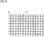
- FIG. 16 illustrates an example of arrangement of reinforcing bars in a concrete structure.
- reinforcing bars are used so as to improve strength.
- reinforcing bars S are arranged in a lattice shape, and intersection points thereof are bound with wires.
- end portions E1 of the reinforcing bars S arranged in this way are cut in some cases.
- the two reinforcing bars S at a lattice-shaped lattice place E2 are cut at four places so that a pipe and the like can pass through.
- Scissors configured to cut a round bar-shaped to-be-cut object by a pair of movable blades have a configuration of pressing and cutting diametrically the round bar by acute-angled blade edges. While cutting the round bar by the pair of movable blades, a cutting load, which is applied in a vertical direction relative to an extension direction of the round bar, and a load, which tears off the round bar in the extension direction of the round bar that is the vertical direction relative to the cutting load, are generated.
- nippers configured to cut a relatively thin wire rod such as an electric wire and a wire and to be opened and closed by a hand
- a technology of providing a cutting blade with a wire rod sandwiching member configured to hold the wire rod with an elastic force so as to prevent the wire rod cut as a to-be-cut object from being scattered for example, refer to JP S64-43865 U ).
- the present invention has been made in view of the above situations, and an object thereof is to provide electric scissors capable of holding a to-be-cut object and regulating a direction of the to-be-cut object with respect to a movable blade with a simple configuration.
- Electric scissors includes: at least one movable blade having a blade portion configured to cut a to-be-cut object; a drive unit configured to open and close the at least one movable blade; a holding part configured to hold the to-be-cut object that is cut by the at least one movable blade, and a support part configured to support the to-be-cut object, which is cut by the at least one movable blade, while regulating a direction of the to-be-cut object.
- the to-be-cut object is cut by the movable blade in a state where a direction of the to-be-cut object, which is to be cut by the movable blade, is regulated by the support part and the to-be-cut object is held by the holding part.
- the to-be-cut object while cutting the to-be-cut object by the movable blade, the to-be-cut object is suppressed from being tilted with respect to the movable blade, so that the electric scissors can be suppressed from being tilted with respect to the to-be-cut object.
- the to-be-cut object is held by the holding part while cutting the to-be-cut object by the movable blade, and the cut to-be-cut object can be held by the electric scissors even after the to-be-cut object is cut, so that it is possible to prevent the to-be-cut object from being scattered.
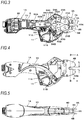
- FIG. 1 is a partially broken perspective view depicting an example of electric scissors of the present embodiment
- FIG. 2 is an exploded perspective view of main parts depicting the example of the electric scissors of the present embodiment
- FIG. 3 is a side sectional view depicting the example of the electric scissors of the present embodiment
- FIG. 4 is a side view depicting the example of the electric scissors of the present embodiment
- FIG. 5 is a top view depicting the example of the electric scissors of the present embodiment
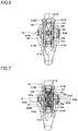
- FIG. 6 is a front view depicting the example of the electric scissors of the present embodiment
- FIG. 7 is a sectional view taken along a line A-A of FIG. 4 , depicting the example of the electric scissors of the present embodiment.
- Electric scissors 1A of the present embodiment include a first movable blade 2A and a second movable blade 2B, which are a pair of movable blades, a first holding part 3A and a second holding part 3B configured to hold a reinforcing bar S, which is a to-be-cut object to be cut by the first movable blade 2A and the second movable blade 2B, and a first support part 4A and a second support part 4B configured to suppress the reinforcing bar S from being tilted with respect to the first movable blade 2A and the second movable blade 2B and to suppress the first holding part 3A and the second holding part 3B from being deformed in a direction other than a desired direction.
- the electric scissors 1A also include a drive unit 5 configured to drive the first movable blade 2A and the second movable blade 2B.
- the first movable blade 2A has a blade portion 20A, which is formed in a plate-shaped member made of steel or the like and having a predetermined shape and has a wedge-shaped section toward one side and an acute-angled blade edge.
- the second movable blade 2B has a blade portion 20B, which is formed in a plate-shaped member made of steel or the like and having a predetermined shape and has a wedge-shaped section toward one side and an acute-angled blade edge.
- the first movable blade 2A is rotatably supported by a shaft 21A supported to the first support part 4A and the second support part 4B.
- the first movable blade 2A is formed with a shaft hole portion 22A in which the shaft 21A is inserted, and has the blade portion 20A formed on one side with the shaft hole portion 22A being interposed therebetween and a link part 23A formed on the other side with the shaft hole portion 22A being interposed therebetween and coupled to the drive unit 5.
- the second movable blade 2B is rotatably supported by a shaft 21B supported to the first support part 4A and the second support part 4B in a direction parallel to the shaft 21A.
- the second movable blade 2B is formed with a shaft hole portion 22B in which the shaft 21B is inserted, and has the blade portion 20B formed on one side with the shaft hole portion 22B being interposed therebetween and a link part 23B formed on the other side with the shaft hole portion 22B being interposed therebetween and coupled to the drive unit 5.
- an extension direction of the blade portion 20A and an extension direction of the blade portion 20B are parallel.
- a position of the blade portion 20A along an axis direction of the shaft 21A and a position of the blade portion 20B along an axis direction of the shaft 21B overlap.
- the first movable blade 2A is moved in directions in which the blade portion 20A comes close to and gets away from the blade portion 20B of the second movable blade 2B.
- the second movable blade 2B is moved in directions in which the blade portion 20B comes close to and gets away from the blade portion 20A of the first movable blade 2A.
- the first movable blade 2A and the second movable blade 2B are moved away from each other, so that a gap, in which a reinforcing bar S is inserted, is formed between the blade portion 20A of the first movable blade 2A and the blade portion 20B of the second movable blade 2B.
- the first movable blade 2A and the second movable blade 2B are moved toward each other, so that the blade portion 20A of the first movable blade 2A and the blade portion 20B of the second movable blade 2B are contacted to each other.
- the first holding part 3A is constituted by an elastic member.
- the first holding part 3A is opened at a portion facing the blade portion 20A of the first movable blade 2A, is attached to the first movable blade 2A in such an aspect of covering both sides of the first movable blade 2A and a back portion of the first movable blade 2A opposite to the blade portion 20A, and is configured to operate in conjunction with opening and closing of the first movable blade 2A.
- the first holding part 3A may also be provided on both sides or one side of the first movable blade 2A in a vertical direction relative to the opening and closing direction of the first movable blade 2A.
- An inner surface-side of the first holding part 3A which faces the blade portion 20A of the first movable blade 2A, has a shape conforming to the blade portion 20A of the first movable blade 2A having a wedge-shaped section.
- the second holding part 3B is constituted by an elastic member.
- the second holding part 3B is opened at a portion facing the blade portion 20B of the second movable blade 2B, is attached to the second movable blade 2B in such an aspect of covering both sides of the second movable blade 2B and a back portion of the second movable blade 2B opposite to the blade portion 20B, and is configured to operate in conjunction with opening and closing of the second movable blade 2B.
- the second holding part 3B may also be provided on both sides or one side of the second movable blade 2B in a vertical direction relative to the opening and closing direction of the second movable blade 2B.
- An inner surface-side of the second holding part 3B which faces the blade portion 20B of the second movable blade 2B, has a shape conforming to the blade portion 20B of the second movable blade 2B having a wedge-shaped section.
- the first movable blade 2A protrudes from the first holding part 3A as the first holding part 3A is elastically deformed.
- a surface of the second holding part 3B, which faces the first holding part 3A attached to the first movable blade 2A, is located in a substantially equal position as the blade portion 20B of the second movable blade 2B.
- the second movable blade 2B protrudes from the second holding part 3B as the second holding part 3B is elastically deformed.
- the first holding part 3A and the second holding part 3B may be formed of urethane, nitrile rubber, chloroprene rubber, ethylene rubber, butyl rubber, fluorine-contained rubber, silicon rubber, high-strength silicon rubber and the like, for example, and urethane is preferably used from viewpoints of compressive stress, hardness, friction coefficient and the like of an elastic body.
- the first support part 4A and the second support part 4B are made of metal plates such as iron.
- the first support part 4A has a groove portion 40A in which the reinforcing bar S is inserted.
- An opened width L of the groove portion 40A is set slightly greater than a diameter (refer to FIG. 4 ) of the reinforcing bar S to be cut.
- the second support part 4B has a groove portion 40B in which the reinforcing bar S is inserted.
- An opened width L of the groove portion 40B is set slightly greater than the diameter of the reinforcing bar S to be cut.
- the first support part 4A and the second support part 4B are fixed to a housing 10 in a state where the first support part 4A and the second support part 4B are fixed to coupling members 41A inserted therebetween by screws 41B and an interval between the first support part 4A and the second support part 4B is kept by the coupling members 41A.
- the groove portion 40A of the first support part 4A and the groove portion 40B of the second support part 4B are provided in positions along the axis directions of the shaft 21A and the shaft 21B with respect to a space between the blade portion 20A and the blade portion 20B opened as the first movable blade 2A and the second movable blade 2B are rotated away from each other.
- the reinforcing bar S inserted between the groove portion 40A of the first support part 4A and the groove portion 40B of the second support part 4B is introduced between the blade portion 20A of the first movable blade 2A and the blade portion 20B of the second movable blade 2B in an opened state.
- the first support part 4A is provided at a part facing one side surfaces in the vertical direction relative to the opening and closing direction of the first movable blade 2A and the first holding part 3A and one side surfaces in the vertical direction relative to the opening and closing direction of the second movable blade 2B and the second holding part 3B.
- the second support part 4B is provided at a part facing the other side surfaces of the first movable blade 2A and the first holding part 3A and the other side surfaces of the second movable blade 2B and the second holding part 3B.
- An interval between the first support part 4A and the second support part 4B is substantially equal to a width of the first holding part 3A in the axis direction of the shaft 21A and a width of the second holding part 3B in the axis direction of the shaft 21B, and the first support part 4A is in contact with one side surfaces of the first holding part 3A and the second holding part 3B. Also, the second support part 4B is in contact with the other side surfaces of the first holding part 3A and the second holding part 3B.
- the first support part 4A is provided with holes 42A and 43A in which one end portions of the shaft 21A and the shaft 21B are inserted, and the second support part 4B is provided with holes 42B and 43B in which the other end portions of the shaft 21A and the shaft 21B are inserted.
- the shaft 21A and the shaft 21B are each fixed via E-rings 24 so that they do not come off from the first support part 4A and the second support part 4B. Thereby, both axial ends of the shaft 21A and the shaft 21B are supported by the first support part 4A and the second support part 4B, so that occurrence of inclination of the axis line between the shaft 21A and the shaft 21B is suppressed.
- the drive unit 5 includes a motor 50, a decelerator 51, a feed screw mechanism 52, and a toggle link mechanism 53.
- a drive shaft of the motor 50 is coupled to the decelerator 51 using a planetary gear, for example.
- the feed screw mechanism 52 has a screw shaft 52A coupled to an output shaft of the decelerator 51, and a movable member 52B having a convex part (not shown) engaged to a screw groove of the screw shaft 52A.
- the toggle link mechanism 53 has a link part 54A rotatably coupled to the link part 23A of the first movable blade 2A, a link part 54B rotatably coupled to the link part 23B of the second movable blade 2B, and a link part 54C configured to couple the link part 54A and link part 54B and the movable member 52B.
- the link part 23A and the link part 54A are coupled to be rotatable about a shaft 55A as a support point.
- the link part 23B and the link part 54B are coupled to be rotatable about a shaft 55B as a support point.
- the link part 54A and link part 54B and the link part 54C are coupled to be rotatable about a shaft 55C as a support point, and the link part 54C and the movable member 52B are coupled to be rotatable about a shaft 55D as a support point.
- the link part 23A of the first movable blade 2A and the link part 54A form a bent shape at a coupled part by the shaft 55A
- the link part 23B of the second movable blade 2B and the link part 54B form a bent shape at a coupled part by the shaft 55B, according to a position of the movable member 52B.
- the link part 23A and the link part 54A form a bent shape at the coupled part by the shaft 55A
- the link part 23B and the link part 54B form a bent shape at the coupled part by the shaft 55B.
- a gap in which the reinforcing bar S is introduced is formed between the blade portion 20A the blade portion 20B.
- the angle between the link part 23A and the link part 54A at the coupled part by the shaft 55A is closed and the angle between the link part 23B and the link part 54B at the coupled part by the shaft 55B is closed by movement of the movable member 52B.
- the first movable blade 2A rotates about the shaft 21A as a support point in a direction in which the angle between the link part 23A and the link part 54A is closed and the second movable blade 2B rotates about the shaft 21B as a support point in a direction in which the angle between the link part 23B and the link part 54B and is closed
- the first movable blade 2A and the second movable blade 2B are moved in a direction in which the blade portions thereof come close to each other, so that the blade portion 20A and the blade portion 20B are contacted to each other.
- the electric scissors 1A include an operation unit 11 configured to perform the opening and closing operations of the first movable blade 2A and the second movable blade 2B.
- the operation unit 11 has a first switch 11A and a second switch 11B configured to control a rotating direction, a rotating amount and a rotating speed of the motor 50.
- the electric scissors 1A may have such an aspect that a power supply unit such as a battery for supplying electricity to the motor 50 and the like is provided independently of the electric scissors 1A and the electric scissors 1A and the power supply unit are connected by a cable.
- the electric scissors 1A may also have such a configuration that a power supply unit such as a battery for supplying electricity to the motor 50 and the like is detachably mounted to the electric scissors 1A. In this case, charging is performed in a state where the power supply unit is detached from the electric scissors 1A.
- the electric scissors 1A may also have such a configuration that a power supply unit such as a battery for supplying electricity to the motor 50 and the like is embedded in the electric scissors 1A. In this case, the power supply unit is charged in a state where the electric scissors 1A and a charger are connected to each other.
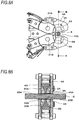
- FIG. 8A is a side sectional view of main parts depicting an example of an operation of the electric scissors of the present embodiment
- FIG. 8B is a sectional view taken along a line B-B of FIG. 8A , depicting an example of the operation of the electric scissors of the present embodiment
- FIG. 9A is a side sectional view of main parts depicting an example of the operation of the electric scissors of the present embodiment
- FIG. 9B is a sectional view taken along a line C-C of FIG. 9A , depicting an example of the operation of the electric scissors of the present embodiment
- FIG. 10 is a side view of main parts depicting an example of the operation of the electric scissors of the present embodiment.
- a gap in which the reinforcing bar S is introduced is formed between the blade portion 20A of the first movable blade 2A and the blade portion 20B of the second movable blade 2B.
- the reinforcing bar S is inserted into the groove portion 40A of the first support part 4A and the groove portion 40B of the second support part 4B, the reinforcing bar S is inserted between the blade portion 20A of the first movable blade 2A and the blade portion 20B of the second movable blade 2B, as shown in FIGS. 8A and 8B .
- the motor 50 rotates in a predetermined direction.
- the rotation of the motor 50 is converted into movement of the movable member 52B by the screw shaft 52A and the movable member 52B of the feed screw mechanism 52, and the movement of the movable member 52B is transmitted to the first movable blade 2A and the second movable blade 2B by the toggle link mechanism 53.
- the first movable blade 2A rotates about the shaft 21A as a support point and the second movable blade 2B rotates about the shaft 21B as a support point in the direction in which the blade portion 20A of the first movable blade 2A and the blade portion 20B of the second movable blade 2B come close to each other.
- the first movable blade 2A and the second movable blade 2B are moved in the direction in which the blade portion 20A and the blade portion 20B come close to each other, so that the blade portion 20A presses and cuts the reinforcing bar S from one side of the reinforcing bar S in a diametrical direction, and the blade portion 20B presses and cuts the reinforcing bar S from the other side of the reinforcing bar S in the diametrical direction, thereby starting cutting the reinforcing bar S.
- FIG. 11A is a side view of main parts of electric scissors depicting a problem of the related art
- FIG. 11B is a sectional view taken along a line D-D of FIG. 11A , depicting the problem of the related art.
- a cutting load F1 which is applied in a vertical direction relative to an extension direction of the reinforcing bar S
- a load F2 which tears off the reinforcing bar S in the extension direction of the reinforcing bar S that is the vertical direction relative to the cutting load F1 are generated.
- the first movable blade 2A and the second movable blade 2B are provided with the holding parts
- the first holding part 3A is pushed and elastically deformed by the reinforcing bar S, so that the blade portion 20A protrudes from the first holding part 3A.
- the blade portion 20B of the second movable blade 2B presses and cuts the reinforcing bar S
- the second holding part 3B is pushed and elastically deformed by the reinforcing bar S, so that the blade portion 20B protrudes from the second holding part 3B.
- the first holding part 3A diametrically pushes the reinforcing bar S from one side by a restoring force
- the second holding part 3B diametrically pushes the reinforcing bar S from the other side by a restoring force.
- the first movable blade 2A and the second movable blade 2B are moved to positions in which the blade portion 20A and the blade portion 20B are contacted to each other, thereby cutting the reinforcing bar S.
- the reinforcing bar S is sandwiched and held between the first holding part 3A and the second holding part 3B, movement of the reinforcing bar S due to the load F2 that tears off the reinforcing bar S in the vertical direction relative to the cutting load F1 is suppressed by the first holding part 3A and the second holding part 3B, as shown in FIG. 9B .
- the cut reinforcing bar S is suppressed from being scattered.
- the blade portion 20A presses and cuts the reinforcing bar S
- the first holding part 3A is pushed and elastically deformed by the reinforcing bar S
- the force by which the first holding part 3A diametrically pushes the reinforcing bar S from one side by the restoring force is weakened.
- first support part 4A is provided on one side part of the first movable blade 2A having the first holding part 3A attached thereto and the second movable blade 2B having the second holding part 3B attached thereto
- second support part 4B is provided on the other side part of the first movable blade 2A having the first holding part 3A attached thereto and the second movable blade 2B having the second holding part 3B attached thereto.
- the blade portion 20A presses and cuts the reinforcing bar S
- the first holding part 3A is pushed and elastically deformed by the reinforcing bar S
- the outward bulging along the extension direction of the reinforcing bar S is suppressed by the first support part 4A and second support part 4B and deformation of the concave portions 30A provided to the first holding part 3A. Therefore, the first holding part 3A is elastically deformed in such an aspect of being compressed in the vertical direction relative to the extension direction of the reinforcing bar S.
- the force by which the first holding part 3A diametrically pushes the reinforcing bar S from one side by the restoring force is increased.
- the blade portion 20B presses and cuts the reinforcing bar S
- the second holding part 3B is pushed and elastically deformed by the reinforcing bar S
- the outward bulging along the extension direction of the reinforcing bar S is suppressed by the first support part 4A and second support part 4B and deformation of the concave portions 30B provided to the second holding part 3B. Therefore, the second holding part 3B is elastically deformed in such an aspect of being compressed in the vertical direction relative to the extension direction of the reinforcing bar S.
- the force by which the second holding part 3B diametrically pushes the reinforcing bar S from one side by the restoring force is increased.
- the material and hardness of the first holding part 3A and the second holding part 3B were selected in consideration of optimal states such as a pressing force against the reinforcing bar S and a deformed state that does not interfere with the cutting of the reinforcing bar S, from viewpoints of compressive stress, hardness, friction coefficient and the like of an elastic body.
- urethane hardness Hs: 70°, compressive stress: 170 to 190N/cm 2 , dynamic friction coefficient: 0.624 to 0.648 was used for the first holding part 3A and the second holding part 3B.
- the reinforcing bar S may be tilted with respect to each of the movable blades, so that the electric scissors are tilted with respect to the reinforcing bar S. For this reason, a worker should press the electric scissors so that the scissors are not tilted, which increases the burden.
- the worker can perform the operation of cutting the reinforcing bar S with gripping the electric scissors 1A with one hand and can freely use the other hand, so that it is possible to secure favorable operability even in a cutting operation at a high place, for example.
- the cut reinforcing bar S can be suppressed from being scattered.
- the closed state of the first movable blade 2A and the second movable blade 2B is kept by operating the operation unit 11, so that it is possible to keep a state where the reinforcing bar S is held by the electric scissors 1A.
- the worker can move to a discard site while holding the cut reinforcing bar S with the electric scissors 1A, and operate the operation unit 11 to open the first movable blade 2A and the second movable blade 2B, thereby discarding the reinforcing bar S at the discard site. Therefore, it is possible to exclude operations of collecting the scattered reinforcing bars S and taking the same to the discard site for discard.
- FIG. 12 is a front sectional view depicting a first modified embodiment of the electric scissors of the present embodiment.
- Electric scissors 1B of the first modified embodiment have a configuration where one of the pair of movable blades is provided with a holding part and the other movable blade is not provided with a holding part. That is, in the electric scissors 1B, the first movable blade 2A is provided with a holding part 3A' and the second movable blade 2B is not provided with a holding part.
- the second movable blade 2B may be provided with a holding part, and the first movable blade 2A may not be provided with a holding part.
- the holding part 3A' may have the same configuration as the first holding part 3A.
- the holding part 3A' is pushed and elastically deformed by the reinforcing bar S.
- the holding part 3A' pushes diametrically the reinforcing bar S from one side by a restoring force.
- FIG. 13 is a front sectional view depicting a second modified embodiment of the electric scissors of the present embodiment.
- Electric scissors 1C of the second modified embodiment include members having a magnetic force where the first holding part 3A has a magnet 31A, and the second holding part 3B has a magnet 31B. Note that, the first holding part 3A and the second holding part 3B may have a magnetic force as a whole.
- the first holding part 3A is pushed and elastically deformed by the reinforcing bar S.
- the holding part 3A pushes diametrically the reinforcing bar S from one side by a restoring force.
- the second holding part 3B is also pushed and elastically deformed by the reinforcing bar S.
- the second holding part 3B pushes diametrically the reinforcing bar S from the other side by a restoring force.
- the magnet 31A of the first holding part 3A is sucked to the reinforcing bar S
- the magnet 31B of the second holding part 3B is sucked to the reinforcing bar S.
- the first movable blade 2A and the second movable blade 2B hold the reinforcing bar S between the first holding part 3A and the second holding part 3B by the elastic deformations of the first holding part 3A and the second holding part 3B and the magnets 31A and 31B. Therefore, the cut reinforcing bar S is suppressed from being scattered.
- FIG. 14 is a front sectional view depicting a third modified embodiment of the electric scissors of the present embodiment.
- electric scissors 1D of the third modified embodiment a position of a surface of the first holding part 3A facing the second holding part 3B is varied with respect to the blade edge of the blade portion 20A of the first movable blade 2A, according to the diameter of the reinforcing bar S.
- a position of a surface of the second holding part 3B facing the first holding part 3A is varied with respect to the blade edge of the blade portion 20B of the second movable blade 2B, according to the diameter of the reinforcing bar S.
- a retreat amount of the first holding part 3A with respect to the blade edge of the blade portion 20A of the first movable blade 2A is increased and a retreat amount of the second holding part 3B with respect to the blade edge of the blade portion 20B of the second movable blade 2B is increased, thereby widening the interval between the first holding part 3A and the second holding part 3B.
- the load is suppressed from being excessive when the first movable blade 2A and the second movable blade 2B are rotated.
- FIG. 15 is a front sectional view depicting a fourth modified embodiment of the electric scissors of the present embodiment.
- electric scissors 1E of the fourth modified embodiment a blade edge of a blade portion 20C of a first movable blade 2C and a blade edge of a blade portion 20D of a second movable blade 2D are each formed to have an obtuse angle.
- the cutting load F1 which is applied in the vertical direction relative to the extension direction of the reinforcing bar S
- the load F2 which tears off the reinforcing bar S in the extension direction of the reinforcing bar S that is the vertical direction relative to the cutting load F1
- the blade edge of the blade portion 20C of the first movable blade 2C and the blade edge of the blade portion 20D of the second movable blade 2D are formed to have an obtuse angle
- the load F2 that tears off the reinforcing bar S is sufficiently reduced with respect to the cutting load F1. Thereby, the cut reinforcing bar S is dropped along the moving direction of the movable blade and is suppressed from being scattered.
Landscapes
- Engineering & Computer Science (AREA)
- Mechanical Engineering (AREA)
- Life Sciences & Earth Sciences (AREA)
- Forests & Forestry (AREA)
- Scissors And Nippers (AREA)
- Shearing Machines (AREA)
Abstract
Description
- The present invention relates to electric scissors configured to cut a to-be-cut object such as a reinforcing bar by using a drive force of a motor.
-
FIG. 16 illustrates an example of arrangement of reinforcing bars in a concrete structure. For concrete structures, reinforcing bars are used so as to improve strength. As shown inFIG. 16 , reinforcing bars S are arranged in a lattice shape, and intersection points thereof are bound with wires. On construction sites, end portions E1 of the reinforcing bars S arranged in this way are cut in some cases. In some cases, the two reinforcing bars S at a lattice-shaped lattice place E2 are cut at four places so that a pipe and the like can pass through. - Scissors configured to cut a round bar-shaped to-be-cut object by a pair of movable blades have a configuration of pressing and cutting diametrically the round bar by acute-angled blade edges. While cutting the round bar by the pair of movable blades, a cutting load, which is applied in a vertical direction relative to an extension direction of the round bar, and a load, which tears off the round bar in the extension direction of the round bar that is the vertical direction relative to the cutting load, are generated.
- With the scissors of the related art, it is not possible to suppress the round bar from moving due to the load that tears off the round bar in the vertical direction relative to the cutting load. Thereby, when the reinforcing bars S arranged as shown in
FIG. 16 are cut at the cutting places by the pair of movable blades, the reinforcing bars S are applied with a force of moving the same in the extension direction, so that the cut reinforcing bars S are scattered. - In contrast, as for nippers configured to cut a relatively thin wire rod such as an electric wire and a wire and to be opened and closed by a hand, suggested is a technology of providing a cutting blade with a wire rod sandwiching member configured to hold the wire rod with an elastic force so as to prevent the wire rod cut as a to-be-cut object from being scattered (for example, refer to
JP S64-43865 U - On the other hand, in order to cut a reinforcing bar and a thick round bar, which are to-be-cut objects, it is necessary to apply a higher cutting force. As described above, while cutting the round bar by the pair of movable blades, a reactive force to the cutting load applied in the vertical direction relative to the extension direction of the round bar is applied to the movable blades. For this reason, when the higher cutting force is applied, the scissors are tilted relative to the round bar. For this reason, a worker should press the scissors so that the scissors are not tilted.
- Therefore, suggested is a technology of preventing a pipe, which is a to-be-cut object, from being tilted by providing pressing members configured to hold the pipe by urging of torsion springs on both sides of a cutting blade (for example, refer to
JP 2005-87642 A - However, in the configuration where the to-be-cut object is pressed using the urging of the spring, it is necessary to provide a further stronger torsion spring so as to cut a round bar having a large diameter, which increases a size of a tool and deteriorates operability of the tool.
- The present invention has been made in view of the above situations, and an object thereof is to provide electric scissors capable of holding a to-be-cut object and regulating a direction of the to-be-cut object with respect to a movable blade with a simple configuration.
- Electric scissors according to an aspect of the present invention includes: at least one movable blade having a blade portion configured to cut a to-be-cut object; a drive unit configured to open and close the at least one movable blade; a holding part configured to hold the to-be-cut object that is cut by the at least one movable blade, and a support part configured to support the to-be-cut object, which is cut by the at least one movable blade, while regulating a direction of the to-be-cut object.
- In the aspect of the present invention, the to-be-cut object is cut by the movable blade in a state where a direction of the to-be-cut object, which is to be cut by the movable blade, is regulated by the support part and the to-be-cut object is held by the holding part.
- According to the aspect of the present invention, while cutting the to-be-cut object by the movable blade, the to-be-cut object is suppressed from being tilted with respect to the movable blade, so that the electric scissors can be suppressed from being tilted with respect to the to-be-cut object. In addition, the to-be-cut object is held by the holding part while cutting the to-be-cut object by the movable blade, and the cut to-be-cut object can be held by the electric scissors even after the to-be-cut object is cut, so that it is possible to prevent the to-be-cut object from being scattered.
-
-
FIG. 1 is a partially broken perspective view depicting an example of electric scissors of the present embodiment. -
FIG. 2 is an exploded perspective view of main parts depicting the example of the electric scissors of the present embodiment. -
FIG. 3 is a side sectional view depicting the example of the electric scissors of the present embodiment. -
FIG. 4 is a side view depicting the example of the electric scissors of the present embodiment. -
FIG. 5 is a top view depicting the example of the electric scissors of the present embodiment. -
FIG. 6 is a front view depicting the example of the electric scissors of the present embodiment. -
FIG. 7 is a sectional view taken along a line A-A ofFIG. 4 , depicting the example of the electric scissors of the present embodiment. -
FIG. 8A is a side sectional view of main parts depicting an example of an operation of the electric scissors of the present embodiment. -
FIG. 8B is a sectional view taken along a line B-B ofFIG. 8A , depicting an example of the operation of the electric scissors of the present embodiment. -
FIG. 9A is a side sectional view of main parts depicting an example of the operation of the electric scissors of the present embodiment. -
FIG. 9B is a sectional view taken along a line C-C ofFIG. 9A , depicting an example of the operation of the electric scissors of the present embodiment. -
FIG. 10 is a side view of main parts depicting an example of the operation of the electric scissors of the present embodiment. -
FIG. 11A is a side view of main parts of electric scissors depicting a problem of the related art. -
FIG. 11B is a sectional view taken along a line D-D ofFIG. 11A , depicting the problem of the related art. -
FIG. 12 is a front sectional view depicting a first modified embodiment of the electric scissors of the present embodiment. -
FIG. 13 is a front sectional view depicting a second modified embodiment of the electric scissors of the present embodiment. -
FIG. 14 is a front sectional view depicting a third modified embodiment of the electric scissors of the present embodiment. -
FIG. 15 is a front sectional view depicting a fourth modified embodiment of the electric scissors of the present embodiment. -
FIG. 16 illustrates an example of arrangement of reinforcing bars in a concrete structure. - Hereinbelow, embodiments of the electric scissors of the present invention will be described with reference to the drawings.
-
FIG. 1 is a partially broken perspective view depicting an example of electric scissors of the present embodiment, andFIG. 2 is an exploded perspective view of main parts depicting the example of the electric scissors of the present embodiment.FIG. 3 is a side sectional view depicting the example of the electric scissors of the present embodiment,FIG. 4 is a side view depicting the example of the electric scissors of the present embodiment, andFIG. 5 is a top view depicting the example of the electric scissors of the present embodiment.FIG. 6 is a front view depicting the example of the electric scissors of the present embodiment, andFIG. 7 is a sectional view taken along a line A-A ofFIG. 4 , depicting the example of the electric scissors of the present embodiment. -
Electric scissors 1A of the present embodiment include a firstmovable blade 2A and a secondmovable blade 2B, which are a pair of movable blades, afirst holding part 3A and asecond holding part 3B configured to hold a reinforcing bar S, which is a to-be-cut object to be cut by the firstmovable blade 2A and the secondmovable blade 2B, and afirst support part 4A and asecond support part 4B configured to suppress the reinforcing bar S from being tilted with respect to the firstmovable blade 2A and the secondmovable blade 2B and to suppress the first holdingpart 3A and thesecond holding part 3B from being deformed in a direction other than a desired direction. Theelectric scissors 1A also include adrive unit 5 configured to drive the firstmovable blade 2A and the secondmovable blade 2B. - The first
movable blade 2A has ablade portion 20A, which is formed in a plate-shaped member made of steel or the like and having a predetermined shape and has a wedge-shaped section toward one side and an acute-angled blade edge. The secondmovable blade 2B has ablade portion 20B, which is formed in a plate-shaped member made of steel or the like and having a predetermined shape and has a wedge-shaped section toward one side and an acute-angled blade edge. - The first
movable blade 2A is rotatably supported by ashaft 21A supported to thefirst support part 4A and thesecond support part 4B. The firstmovable blade 2A is formed with ashaft hole portion 22A in which theshaft 21A is inserted, and has theblade portion 20A formed on one side with theshaft hole portion 22A being interposed therebetween and alink part 23A formed on the other side with theshaft hole portion 22A being interposed therebetween and coupled to thedrive unit 5. - The second
movable blade 2B is rotatably supported by ashaft 21B supported to thefirst support part 4A and thesecond support part 4B in a direction parallel to theshaft 21A. The secondmovable blade 2B is formed with ashaft hole portion 22B in which theshaft 21B is inserted, and has theblade portion 20B formed on one side with theshaft hole portion 22B being interposed therebetween and alink part 23B formed on the other side with theshaft hole portion 22B being interposed therebetween and coupled to thedrive unit 5. - As for the first
movable blade 2A and the secondmovable blade 2B, an extension direction of theblade portion 20A and an extension direction of theblade portion 20B are parallel. In addition, as for the firstmovable blade 2A and the secondmovable blade 2B, a position of theblade portion 20A along an axis direction of theshaft 21A and a position of theblade portion 20B along an axis direction of theshaft 21B overlap. - During a rotating operation about the
shaft 21A as a support point, the firstmovable blade 2A is moved in directions in which theblade portion 20A comes close to and gets away from theblade portion 20B of the secondmovable blade 2B. In addition, during a rotating operation about theshaft 21B as a support point, the secondmovable blade 2B is moved in directions in which theblade portion 20B comes close to and gets away from theblade portion 20A of the firstmovable blade 2A. - The first
movable blade 2A and the secondmovable blade 2B are moved away from each other, so that a gap, in which a reinforcing bar S is inserted, is formed between theblade portion 20A of the firstmovable blade 2A and theblade portion 20B of the secondmovable blade 2B. In addition, the firstmovable blade 2A and the secondmovable blade 2B are moved toward each other, so that theblade portion 20A of the firstmovable blade 2A and theblade portion 20B of the secondmovable blade 2B are contacted to each other. - The
first holding part 3A is constituted by an elastic member. Thefirst holding part 3A is opened at a portion facing theblade portion 20A of the firstmovable blade 2A, is attached to the firstmovable blade 2A in such an aspect of covering both sides of the firstmovable blade 2A and a back portion of the firstmovable blade 2A opposite to theblade portion 20A, and is configured to operate in conjunction with opening and closing of the firstmovable blade 2A. Note that, the first holdingpart 3A may also be provided on both sides or one side of the firstmovable blade 2A in a vertical direction relative to the opening and closing direction of the firstmovable blade 2A. - An inner surface-side of the first holding
part 3A, which faces theblade portion 20A of the firstmovable blade 2A, has a shape conforming to theblade portion 20A of the firstmovable blade 2A having a wedge-shaped section. An outer surface-side of the first holdingpart 3A, which faces thefirst support part 4A and thesecond support part 4B, is formed withconcave portions 30A for assisting elastic deformation and restoration of the first holdingpart 3A. - The
second holding part 3B is constituted by an elastic member. Thesecond holding part 3B is opened at a portion facing theblade portion 20B of the secondmovable blade 2B, is attached to the secondmovable blade 2B in such an aspect of covering both sides of the secondmovable blade 2B and a back portion of the secondmovable blade 2B opposite to theblade portion 20B, and is configured to operate in conjunction with opening and closing of the secondmovable blade 2B. Note that, thesecond holding part 3B may also be provided on both sides or one side of the secondmovable blade 2B in a vertical direction relative to the opening and closing direction of the secondmovable blade 2B. - An inner surface-side of the
second holding part 3B, which faces theblade portion 20B of the secondmovable blade 2B, has a shape conforming to theblade portion 20B of the secondmovable blade 2B having a wedge-shaped section. An outer surface-side of thesecond holding part 3B, which faces thefirst support part 4A and thesecond support part 4B, is formed withconcave portions 30B for assisting elastic deformation and restoration of thesecond holding part 3B. - A surface of the first holding
part 3A, which faces thesecond holding part 3B attached to the secondmovable blade 2B, is located in a substantially equal position as theblade portion 20A of the firstmovable blade 2A. The firstmovable blade 2A protrudes from the first holdingpart 3A as the first holdingpart 3A is elastically deformed. A surface of thesecond holding part 3B, which faces the first holdingpart 3A attached to the firstmovable blade 2A, is located in a substantially equal position as theblade portion 20B of the secondmovable blade 2B. The secondmovable blade 2B protrudes from thesecond holding part 3B as thesecond holding part 3B is elastically deformed. - The
first holding part 3A and thesecond holding part 3B may be formed of urethane, nitrile rubber, chloroprene rubber, ethylene rubber, butyl rubber, fluorine-contained rubber, silicon rubber, high-strength silicon rubber and the like, for example, and urethane is preferably used from viewpoints of compressive stress, hardness, friction coefficient and the like of an elastic body. - The
first support part 4A and thesecond support part 4B are made of metal plates such as iron. Thefirst support part 4A has agroove portion 40A in which the reinforcing bar S is inserted. An opened width L of thegroove portion 40A is set slightly greater than a diameter (refer toFIG. 4 ) of the reinforcing bar S to be cut. Thesecond support part 4B has agroove portion 40B in which the reinforcing bar S is inserted. An opened width L of thegroove portion 40B is set slightly greater than the diameter of the reinforcing bar S to be cut. - The
first support part 4A and thesecond support part 4B are fixed to ahousing 10 in a state where thefirst support part 4A and thesecond support part 4B are fixed tocoupling members 41A inserted therebetween byscrews 41B and an interval between thefirst support part 4A and thesecond support part 4B is kept by thecoupling members 41A. - The
groove portion 40A of thefirst support part 4A and thegroove portion 40B of thesecond support part 4B are provided in positions along the axis directions of theshaft 21A and theshaft 21B with respect to a space between theblade portion 20A and theblade portion 20B opened as the firstmovable blade 2A and the secondmovable blade 2B are rotated away from each other. Thereby, the reinforcing bar S inserted between thegroove portion 40A of thefirst support part 4A and thegroove portion 40B of thesecond support part 4B is introduced between theblade portion 20A of the firstmovable blade 2A and theblade portion 20B of the secondmovable blade 2B in an opened state. - The
first support part 4A is provided at a part facing one side surfaces in the vertical direction relative to the opening and closing direction of the firstmovable blade 2A and the first holdingpart 3A and one side surfaces in the vertical direction relative to the opening and closing direction of the secondmovable blade 2B and thesecond holding part 3B. Also, thesecond support part 4B is provided at a part facing the other side surfaces of the firstmovable blade 2A and the first holdingpart 3A and the other side surfaces of the secondmovable blade 2B and thesecond holding part 3B. An interval between thefirst support part 4A and thesecond support part 4B is substantially equal to a width of the first holdingpart 3A in the axis direction of theshaft 21A and a width of thesecond holding part 3B in the axis direction of theshaft 21B, and thefirst support part 4A is in contact with one side surfaces of the first holdingpart 3A and thesecond holding part 3B. Also, thesecond support part 4B is in contact with the other side surfaces of the first holdingpart 3A and thesecond holding part 3B. - The
first support part 4A is provided withholes shaft 21A and theshaft 21B are inserted, and thesecond support part 4B is provided withholes shaft 21A and theshaft 21B are inserted. - The
shaft 21A and theshaft 21B are each fixed via E-rings 24 so that they do not come off from thefirst support part 4A and thesecond support part 4B. Thereby, both axial ends of theshaft 21A and theshaft 21B are supported by thefirst support part 4A and thesecond support part 4B, so that occurrence of inclination of the axis line between theshaft 21A and theshaft 21B is suppressed. - The
drive unit 5 includes amotor 50, adecelerator 51, afeed screw mechanism 52, and atoggle link mechanism 53. A drive shaft of themotor 50 is coupled to thedecelerator 51 using a planetary gear, for example. Thefeed screw mechanism 52 has ascrew shaft 52A coupled to an output shaft of thedecelerator 51, and amovable member 52B having a convex part (not shown) engaged to a screw groove of thescrew shaft 52A. - In the
feed screw mechanism 52, when thescrew shaft 52A is rotationally driven, themovable member 52B is linearly moved along thescrew shaft 52A. Thereby, in thefeed screw mechanism 52, a rotating operation of themotor 50 is converted into a linear operation of themovable member 52B, and a moving direction of themovable member 52B is switched according to a rotating direction of themotor 50. - The
toggle link mechanism 53 has alink part 54A rotatably coupled to thelink part 23A of the firstmovable blade 2A, alink part 54B rotatably coupled to thelink part 23B of the secondmovable blade 2B, and alink part 54C configured to couple thelink part 54A and linkpart 54B and themovable member 52B. - The
link part 23A and thelink part 54A are coupled to be rotatable about ashaft 55A as a support point. Thelink part 23B and thelink part 54B are coupled to be rotatable about ashaft 55B as a support point. Thelink part 54A and linkpart 54B and thelink part 54C are coupled to be rotatable about ashaft 55C as a support point, and thelink part 54C and themovable member 52B are coupled to be rotatable about ashaft 55D as a support point. - In the
toggle link mechanism 53, thelink part 23A of the firstmovable blade 2A and thelink part 54A form a bent shape at a coupled part by theshaft 55A, and thelink part 23B of the secondmovable blade 2B and thelink part 54B form a bent shape at a coupled part by theshaft 55B, according to a position of themovable member 52B. - In the first
movable blade 2A and the secondmovable blade 2B, thelink part 23A and thelink part 54A form a bent shape at the coupled part by theshaft 55A, and thelink part 23B and thelink part 54B form a bent shape at the coupled part by theshaft 55B. In the firstmovable blade 2A and the secondmovable blade 2B, when an angle between thelink part 23A and thelink part 54A and an angle between thelink part 23B and thelink part 54B are opened, a gap in which the reinforcing bar S is introduced is formed between theblade portion 20A theblade portion 20B. - In the
toggle link mechanism 53, the angle between thelink part 23A and thelink part 54A at the coupled part by theshaft 55A is closed and the angle between thelink part 23B and thelink part 54B at the coupled part by theshaft 55B is closed by movement of themovable member 52B. - When the first
movable blade 2A rotates about theshaft 21A as a support point in a direction in which the angle between thelink part 23A and thelink part 54A is closed and the secondmovable blade 2B rotates about theshaft 21B as a support point in a direction in which the angle between thelink part 23B and thelink part 54B and is closed, the firstmovable blade 2A and the secondmovable blade 2B are moved in a direction in which the blade portions thereof come close to each other, so that theblade portion 20A and theblade portion 20B are contacted to each other. - The
electric scissors 1A include anoperation unit 11 configured to perform the opening and closing operations of the firstmovable blade 2A and the secondmovable blade 2B. Theoperation unit 11 has afirst switch 11A and asecond switch 11B configured to control a rotating direction, a rotating amount and a rotating speed of themotor 50. - The
electric scissors 1A may have such an aspect that a power supply unit such as a battery for supplying electricity to themotor 50 and the like is provided independently of theelectric scissors 1A and theelectric scissors 1A and the power supply unit are connected by a cable. Theelectric scissors 1A may also have such a configuration that a power supply unit such as a battery for supplying electricity to themotor 50 and the like is detachably mounted to theelectric scissors 1A. In this case, charging is performed in a state where the power supply unit is detached from theelectric scissors 1A. Theelectric scissors 1A may also have such a configuration that a power supply unit such as a battery for supplying electricity to themotor 50 and the like is embedded in theelectric scissors 1A. In this case, the power supply unit is charged in a state where theelectric scissors 1A and a charger are connected to each other. -
FIG. 8A is a side sectional view of main parts depicting an example of an operation of the electric scissors of the present embodiment, andFIG. 8B is a sectional view taken along a line B-B ofFIG. 8A , depicting an example of the operation of the electric scissors of the present embodiment.FIG. 9A is a side sectional view of main parts depicting an example of the operation of the electric scissors of the present embodiment, andFIG. 9B is a sectional view taken along a line C-C ofFIG. 9A , depicting an example of the operation of the electric scissors of the present embodiment.FIG. 10 is a side view of main parts depicting an example of the operation of the electric scissors of the present embodiment. - In a standby state of the
electric scissors 1A, a gap in which the reinforcing bar S is introduced is formed between theblade portion 20A of the firstmovable blade 2A and theblade portion 20B of the secondmovable blade 2B. In this state, as shown inFIG. 10 , when the reinforcing bar S is inserted into thegroove portion 40A of thefirst support part 4A and thegroove portion 40B of thesecond support part 4B, the reinforcing bar S is inserted between theblade portion 20A of the firstmovable blade 2A and theblade portion 20B of the secondmovable blade 2B, as shown inFIGS. 8A and 8B . - When the
first switch 11A of theoperation unit 11 is operated in the state where the reinforcing bar S is inserted between theblade portion 20A and theblade portion 20B, themotor 50 rotates in a predetermined direction. The rotation of themotor 50 is converted into movement of themovable member 52B by thescrew shaft 52A and themovable member 52B of thefeed screw mechanism 52, and the movement of themovable member 52B is transmitted to the firstmovable blade 2A and the secondmovable blade 2B by thetoggle link mechanism 53. Thereby, the firstmovable blade 2A rotates about theshaft 21A as a support point and the secondmovable blade 2B rotates about theshaft 21B as a support point in the direction in which theblade portion 20A of the firstmovable blade 2A and theblade portion 20B of the secondmovable blade 2B come close to each other. - The first
movable blade 2A and the secondmovable blade 2B are moved in the direction in which theblade portion 20A and theblade portion 20B come close to each other, so that theblade portion 20A presses and cuts the reinforcing bar S from one side of the reinforcing bar S in a diametrical direction, and theblade portion 20B presses and cuts the reinforcing bar S from the other side of the reinforcing bar S in the diametrical direction, thereby starting cutting the reinforcing bar S. -
FIG. 11A is a side view of main parts of electric scissors depicting a problem of the related art, andFIG. 11B is a sectional view taken along a line D-D ofFIG. 11A , depicting the problem of the related art. - While cutting the reinforcing bar S by the first
movable blade 2A and the secondmovable blade 2B, as shown inFIG. 11B , a cutting load F1, which is applied in a vertical direction relative to an extension direction of the reinforcing bar S, and a load F2, which tears off the reinforcing bar S in the extension direction of the reinforcing bar S that is the vertical direction relative to the cutting load F1, are generated. - As shown in
FIGS. 11A and 11B , in a configuration where the firstmovable blade 2A and the secondmovable blade 2B are not provided with the holding parts, it is not possible to suppress the reinforcing bar S from moving due to the load F2 that tears off the reinforcing bar S in the vertical direction relative to the cutting load F1. Thereby, the cut reinforcing bar S is scattered. - In contrast, in the configuration where the first
movable blade 2A and the secondmovable blade 2B are provided with the holding parts, while theblade portion 20A of the firstmovable blade 2A presses and cuts the reinforcing bar S, the first holdingpart 3A is pushed and elastically deformed by the reinforcing bar S, so that theblade portion 20A protrudes from the first holdingpart 3A. Also, while theblade portion 20B of the secondmovable blade 2B presses and cuts the reinforcing bar S, thesecond holding part 3B is pushed and elastically deformed by the reinforcing bar S, so that theblade portion 20B protrudes from thesecond holding part 3B. - On the other hand, the first holding
part 3A diametrically pushes the reinforcing bar S from one side by a restoring force, and thesecond holding part 3B diametrically pushes the reinforcing bar S from the other side by a restoring force. Thereby, during the rotating operation where the firstmovable blade 2A and the secondmovable blade 2B move in the direction in which theblade portion 20A and theblade portion 20B come close to each other, the firstmovable blade 2A and the secondmovable blade 2B sandwich and hold the reinforcing bar S between the first holdingpart 3A and thesecond holding part 3B. - The first
movable blade 2A and the secondmovable blade 2B are moved to positions in which theblade portion 20A and theblade portion 20B are contacted to each other, thereby cutting the reinforcing bar S. While pushing and cutting the reinforcing bar S, since the reinforcing bar S is sandwiched and held between the first holdingpart 3A and thesecond holding part 3B, movement of the reinforcing bar S due to the load F2 that tears off the reinforcing bar S in the vertical direction relative to the cutting load F1 is suppressed by the first holdingpart 3A and thesecond holding part 3B, as shown inFIG. 9B . Thereby, the cut reinforcing bar S is suppressed from being scattered. - In addition, while the
blade portion 20A presses and cuts the reinforcing bar S, when the first holdingpart 3A is pushed and elastically deformed by the reinforcing bar S, if the first holdingpart 3A is deformed in a direction in which it bulges outward along the extension direction of the reinforcing bar S, the force by which the first holdingpart 3A diametrically pushes the reinforcing bar S from one side by the restoring force is weakened. Similarly, while theblade portion 20B presses and cuts the reinforcing bar S, when thesecond holding part 3B is pushed and elastically deformed by the reinforcing bar S, if thesecond holding part 3B is deformed in a direction in which it bulges outward along the extension direction of the reinforcing bar S, the force by which thesecond holding part 3B diametrically pushes the reinforcing bar S from one side by the restoring force is weakened. - In contrast, the
first support part 4A is provided on one side part of the firstmovable blade 2A having the first holdingpart 3A attached thereto and the secondmovable blade 2B having thesecond holding part 3B attached thereto, and thesecond support part 4B is provided on the other side part of the firstmovable blade 2A having the first holdingpart 3A attached thereto and the secondmovable blade 2B having thesecond holding part 3B attached thereto. - Thereby, while the
blade portion 20A presses and cuts the reinforcing bar S, when the first holdingpart 3A is pushed and elastically deformed by the reinforcing bar S, the outward bulging along the extension direction of the reinforcing bar S is suppressed by thefirst support part 4A andsecond support part 4B and deformation of theconcave portions 30A provided to the first holdingpart 3A. Therefore, the first holdingpart 3A is elastically deformed in such an aspect of being compressed in the vertical direction relative to the extension direction of the reinforcing bar S. Thereby, the force by which the first holdingpart 3A diametrically pushes the reinforcing bar S from one side by the restoring force is increased. - In addition, while the
blade portion 20B presses and cuts the reinforcing bar S, when thesecond holding part 3B is pushed and elastically deformed by the reinforcing bar S, the outward bulging along the extension direction of the reinforcing bar S is suppressed by thefirst support part 4A andsecond support part 4B and deformation of theconcave portions 30B provided to thesecond holding part 3B. Therefore, thesecond holding part 3B is elastically deformed in such an aspect of being compressed in the vertical direction relative to the extension direction of the reinforcing bar S. Thereby, the force by which thesecond holding part 3B diametrically pushes the reinforcing bar S from one side by the restoring force is increased. - Note that, the material and hardness of the first holding
part 3A and thesecond holding part 3B were selected in consideration of optimal states such as a pressing force against the reinforcing bar S and a deformed state that does not interfere with the cutting of the reinforcing bar S, from viewpoints of compressive stress, hardness, friction coefficient and the like of an elastic body. In the present embodiment, urethane (hardness Hs: 70°, compressive stress: 170 to 190N/cm2, dynamic friction coefficient: 0.624 to 0.648) was used for the first holdingpart 3A and thesecond holding part 3B. - Further, while the
blade portion 20A and theblade portion 20B press and cut the reinforcing bar S, a reactive force to the cutting load F1 that is applied in the vertical direction relative to the extension direction of the reinforcing bar S is applied to the firstmovable blade 2A and the secondmovable blade 2B. In a configuration where thefirst support part 4A and thesecond support part 4B are not provided, the reinforcing bar S may be tilted with respect to each of the movable blades, so that the electric scissors are tilted with respect to the reinforcing bar S. For this reason, a worker should press the electric scissors so that the scissors are not tilted, which increases the burden. - In contrast, in the configuration where the
first support part 4A having thegroove portion 40A in which the reinforcing bar S is introduced is provided on one side part of the firstmovable blade 2A and the secondmovable blade 2B and thesecond support part 4B having thegroove portion 40B in which the reinforcing bar S is introduced is provided on the other side part of the firstmovable blade 2A and the secondmovable blade 2B, a position of the reinforcing bar S is regulated on both sides of the firstmovable blade 2A and the secondmovable blade 2B along the axis directions of theshaft 21A and theshaft 21B. - Thereby, even when the reactive force to the cutting load F1 that is applied in the vertical direction relative to the extension direction of the reinforcing bar S is applied to the first
movable blade 2A and the secondmovable blade 2B, the reinforcing bar S is suppressed from being tilted with respect to the firstmovable blade 2A and the secondmovable blade 2B. Therefore, even though the worker does not apply the force for pressing theelectric scissors 1A so that the scissors are not tilted, theelectric scissors 1A are suppressed from being tilted with respect to the reinforcing bar S. - Therefore, the worker can perform the operation of cutting the reinforcing bar S with gripping the
electric scissors 1A with one hand and can freely use the other hand, so that it is possible to secure favorable operability even in a cutting operation at a high place, for example. In addition, the cut reinforcing bar S can be suppressed from being scattered. Further, after cutting the reinforcing bar S, the closed state of the firstmovable blade 2A and the secondmovable blade 2B is kept by operating theoperation unit 11, so that it is possible to keep a state where the reinforcing bar S is held by theelectric scissors 1A. Therefore, the worker can move to a discard site while holding the cut reinforcing bar S with theelectric scissors 1A, and operate theoperation unit 11 to open the firstmovable blade 2A and the secondmovable blade 2B, thereby discarding the reinforcing bar S at the discard site. Therefore, it is possible to exclude operations of collecting the scattered reinforcing bars S and taking the same to the discard site for discard. -
FIG. 12 is a front sectional view depicting a first modified embodiment of the electric scissors of the present embodiment.Electric scissors 1B of the first modified embodiment have a configuration where one of the pair of movable blades is provided with a holding part and the other movable blade is not provided with a holding part. That is, in theelectric scissors 1B, the firstmovable blade 2A is provided with a holdingpart 3A' and the secondmovable blade 2B is not provided with a holding part. Alternatively, although not shown, the secondmovable blade 2B may be provided with a holding part, and the firstmovable blade 2A may not be provided with a holding part. The holdingpart 3A' may have the same configuration as the first holdingpart 3A. - In the
electric scissors 1B, while pressing and cutting the reinforcing bar S by theblade portion 20A of the firstmovable blade 2A and theblade portion 20B of the secondmovable blade 2B, the holdingpart 3A' is pushed and elastically deformed by the reinforcing bar S. On the other hand, the holdingpart 3A' pushes diametrically the reinforcing bar S from one side by a restoring force. Thereby, when theblade portion 20A of the firstmovable blade 2A and theblade portion 20B of the secondmovable blade 2B are moved toward each other, the reinforcing bar S is sandwiched and held between the holdingpart 3A' and thegroove portion 40A of thefirst support part 4A andgroove portion 40B of thesecond support part 4B. Thereby, the cut reinforcing bar S is suppressed from being scattered. -
FIG. 13 is a front sectional view depicting a second modified embodiment of the electric scissors of the present embodiment.Electric scissors 1C of the second modified embodiment include members having a magnetic force where the first holdingpart 3A has amagnet 31A, and thesecond holding part 3B has amagnet 31B. Note that, the first holdingpart 3A and thesecond holding part 3B may have a magnetic force as a whole. - In the
electric scissors 1C, while pressing and cutting the reinforcing bar S by theblade portion 20A of the firstmovable blade 2A and theblade portion 20B of the secondmovable blade 2B, the first holdingpart 3A is pushed and elastically deformed by the reinforcing bar S. On the other hand, the holdingpart 3A pushes diametrically the reinforcing bar S from one side by a restoring force. Thesecond holding part 3B is also pushed and elastically deformed by the reinforcing bar S. On the other hand, thesecond holding part 3B pushes diametrically the reinforcing bar S from the other side by a restoring force. In addition, themagnet 31A of the first holdingpart 3A is sucked to the reinforcing bar S, and themagnet 31B of thesecond holding part 3B is sucked to the reinforcing bar S. - Thereby, during the rotating operation where the
blade portion 20A and theblade portion 20B are moved toward each other, the firstmovable blade 2A and the secondmovable blade 2B hold the reinforcing bar S between the first holdingpart 3A and thesecond holding part 3B by the elastic deformations of the first holdingpart 3A and thesecond holding part 3B and themagnets -
FIG. 14 is a front sectional view depicting a third modified embodiment of the electric scissors of the present embodiment. Inelectric scissors 1D of the third modified embodiment, a position of a surface of the first holdingpart 3A facing thesecond holding part 3B is varied with respect to the blade edge of theblade portion 20A of the firstmovable blade 2A, according to the diameter of the reinforcing bar S. In addition, a position of a surface of thesecond holding part 3B facing the first holdingpart 3A is varied with respect to the blade edge of theblade portion 20B of the secondmovable blade 2B, according to the diameter of the reinforcing bar S. - For example, in a case where the diameter of the reinforcing bar S is large, a retreat amount of the first holding
part 3A with respect to the blade edge of theblade portion 20A of the firstmovable blade 2A is increased and a retreat amount of thesecond holding part 3B with respect to the blade edge of theblade portion 20B of the secondmovable blade 2B is increased, thereby widening the interval between the first holdingpart 3A and thesecond holding part 3B. In contrast, when the diameter of the reinforcing bar S is small, the retreat amount of the first holdingpart 3A with respect to the blade edge of theblade portion 20A of the firstmovable blade 2A is reduced and the retreat amount of thesecond holding part 3B with respect to the blade edge of theblade portion 20B of the secondmovable blade 2B is reduced, thereby narrowing the interval between the first holdingpart 3A and thesecond holding part 3B. - Thereby, when the first holding
part 3A and thesecond holding part 3B are elastically deformed, the amount of deformation is suppressed from being excessive or too small, and the reinforcing bar S can be securely held. In addition, the load is suppressed from being excessive when the firstmovable blade 2A and the secondmovable blade 2B are rotated. -
FIG. 15 is a front sectional view depicting a fourth modified embodiment of the electric scissors of the present embodiment. Inelectric scissors 1E of the fourth modified embodiment, a blade edge of a blade portion 20C of a first movable blade 2C and a blade edge of a blade portion 20D of a second movable blade 2D are each formed to have an obtuse angle. - While cutting the reinforcing bar S by the first movable blade 2C and the second movable blade 2D, the cutting load F1, which is applied in the vertical direction relative to the extension direction of the reinforcing bar S, and the load F2, which tears off the reinforcing bar S in the extension direction of the reinforcing bar S that is the vertical direction relative to the cutting load F1, are generated. When the blade edge of the blade portion 20C of the first movable blade 2C and the blade edge of the blade portion 20D of the second movable blade 2D are formed to have an obtuse angle, the load F2 that tears off the reinforcing bar S is sufficiently reduced with respect to the cutting load F1. Thereby, the cut reinforcing bar S is dropped along the moving direction of the movable blade and is suppressed from being scattered.
Claims (13)
- Electric scissors comprising:at least one movable blade having a blade portion configured to cut a to-be-cut object;a drive unit configured to open and close the at least one movable blade;a holding part configured to hold the to-be-cut object that is cut by the at least one movable blade; anda support part configured to support the to-be-cut object, which is cut by the at least one movable blade, while regulating a direction of the to-be-cut object.
- The electric scissors according to Claim 1, wherein the holding part is attached to the at least one movable blade and is configured to operate in conjunction with opening and closing of the at least one movable blade.
- The electric scissors according to Claim 1 or 2, wherein the support part is a component independent of the at least one movable blade, and is configured not to operate in conjunction with opening and closing of the at least one movable blade.
- The electric scissors according to one of Claims 1 to 3, wherein the support part is provided on both sides of the at least one movable blade in a vertical direction relative to an opening and closing direction of the at least one movable blade.
- The electric scissors according to one of Claims 1 to 4, wherein the holding part is provided on one side or both sides of the at least one movable blade in a vertical direction relative to an opening and closing direction of the at least one movable blade.
- The electric scissors according to Claim 5, wherein the support part is provided on an outer side of the holding part in the vertical direction relative to the opening and closing direction of the at least one movable blade, and is in contact with the holding part.
- The electric scissors according to one of Claims 1 to 6, wherein the at least one movable blade includes a pair of movable blades configured to open and close in directions in which blade portions thereof come close to and get away from each other, and
wherein the holding part is provided to one or both movable blades of the pair of movable blades. - The electric scissors according to one of Claims 1 to 7, wherein the holding part is constituted by an elastic member.
- The electric scissors according to one of Claims 1 to 8, wherein the holding part is constituted by a member having a magnetic force.
- The electric scissors according to one of Claims 1 to 9, wherein the support part is configured to support the to-be-cut object in an opening and closing direction of the at least one movable blade.
- The electric scissors according to Claim 10, wherein the support part faces the at least one movable blade in a vertical direction relative to the opening and closing direction of the at least one movable blade.
- The electric scissors according to Claim 11, wherein the support part is apart from the at least one movable blade in the vertical direction relative to the opening and closing direction of the at least one movable blade.
- The electric scissors according to any one of Claims 10 to 12, wherein the support part includes a groove portion into which the to-be-cut object is inserted, and
wherein the groove portion is provided in a position along a vertical direction relative to the opening and closing direction of the at least one movable blade with respect to a space, which is formed by the at least one movable blade in an opened state, into which the to-be-cut object is introduced.
Applications Claiming Priority (1)
| Application Number | Priority Date | Filing Date | Title |
|---|---|---|---|
| JP2020080673A JP7396189B2 (en) | 2020-04-30 | 2020-04-30 | electric scissors |
Publications (3)
| Publication Number | Publication Date |
|---|---|
| EP3904021A1 true EP3904021A1 (en) | 2021-11-03 |
| EP3904021C0 EP3904021C0 (en) | 2025-02-19 |
| EP3904021B1 EP3904021B1 (en) | 2025-02-19 |
Family
ID=75728570
Family Applications (1)
| Application Number | Title | Priority Date | Filing Date |
|---|---|---|---|
| EP21170703.9A Active EP3904021B1 (en) | 2020-04-30 | 2021-04-27 | Electric scissors |
Country Status (8)
| Country | Link |
|---|---|
| US (1) | US12042946B2 (en) |
| EP (1) | EP3904021B1 (en) |
| JP (2) | JP7396189B2 (en) |
| CN (1) | CN113580208A (en) |
| AU (1) | AU2021202636B2 (en) |
| ES (1) | ES3015663T3 (en) |
| PL (1) | PL3904021T3 (en) |
| TW (1) | TWI862829B (en) |
Families Citing this family (12)
| Publication number | Priority date | Publication date | Assignee | Title |
|---|---|---|---|---|
| WO2023065028A1 (en) | 2021-10-22 | 2023-04-27 | Ring Rescue Inc. | Ring cutter for safely transecting a ring trapped on an appendage |
| USD1003137S1 (en) * | 2022-03-25 | 2023-10-31 | Innovation Fabrication Commercialisation Infaco | Hedge trimmer |
| JP7785589B2 (en) * | 2022-03-28 | 2025-12-15 | 株式会社関電工 | Cutter head |
| JP2024093744A (en) * | 2022-12-27 | 2024-07-09 | マックス株式会社 | Cutting device |
| JP7905039B2 (en) * | 2022-12-27 | 2026-08-14 | マックス株式会社 | cutting device |
| JP2024093790A (en) * | 2022-12-27 | 2024-07-09 | マックス株式会社 | Cutting device |
| CA3224768A1 (en) | 2022-12-27 | 2024-06-27 | Max Co., Ltd. | Cutting device |
| JP2024093782A (en) * | 2022-12-27 | 2024-07-09 | マックス株式会社 | Cutting device |
| CA3224827A1 (en) | 2022-12-27 | 2024-06-27 | Max Co., Ltd. | Cutting device |
| USD1089340S1 (en) | 2023-06-22 | 2025-08-19 | Ring Rescue Inc. | Ring cutter |
| JP2025035018A (en) | 2023-08-31 | 2025-03-13 | マックス株式会社 | Cutting device |
| JP2026099176A (en) * | 2024-12-06 | 2026-06-18 | マックス株式会社 | cutting blade |
Citations (7)
| Publication number | Priority date | Publication date | Assignee | Title |
|---|---|---|---|---|
| US2775032A (en) * | 1953-10-19 | 1956-12-25 | Edgar P Sorensen | Workpiece-holding pruning shears with resilient in-drawing gripper element |
| JPS6443865U (en) | 1987-09-08 | 1989-03-16 | ||
| US5398415A (en) * | 1994-08-22 | 1995-03-21 | Collins, Jr.; Moseley C. | Cutter with gripper |
| JP2005087642A (en) | 2003-09-19 | 2005-04-07 | Sekisui House Ltd | Pipe cutter |
| JP2006230263A (en) * | 2005-02-24 | 2006-09-07 | Musashi:Kk | Fixture |
| US20150000491A1 (en) * | 2013-06-28 | 2015-01-01 | Premark Packaging Llc | Powered two-stage strap cutter |
| EP3103598A1 (en) * | 2015-06-08 | 2016-12-14 | Makita Corporation | Electrical scissors |
Family Cites Families (31)
| Publication number | Priority date | Publication date | Assignee | Title |
|---|---|---|---|---|
| CA687769A (en) * | 1964-06-02 | Henry H. Townshend, Jr. | Cable cutter | |
| DE610644C (en) * | 1935-03-14 | Georg Seibt A G Dr | Wire cutter | |
| US1279389A (en) * | 1917-05-29 | 1918-09-17 | Albert Malsin | Safety-scissors. |
| US2268728A (en) * | 1941-02-27 | 1942-01-06 | Toop Frederick | Shearing mechanism |
| US2591740A (en) * | 1950-02-03 | 1952-04-08 | Wilber M Stilwell | Child's safety scissors |
| US3010206A (en) * | 1960-09-23 | 1961-11-28 | American Can Co | Safety hand shears |
| US3710445A (en) * | 1971-02-12 | 1973-01-16 | H Roth | A cutter device with illuminated cutting blade |
| JPS49143087U (en) * | 1973-04-05 | 1974-12-10 | ||
| JPS5350157Y2 (en) * | 1975-09-30 | 1978-12-01 | ||
| US4043238A (en) * | 1976-04-21 | 1977-08-23 | Sanders Associates, Inc. | Cable cutter |
| FR2503000B1 (en) * | 1981-04-03 | 1986-11-14 | Gallego Joseph | PORTABLE SHEAR DEVICE FOR SECTIONING ACCIDENTAL VEHICLE BODIES |
| JPS5836024U (en) * | 1981-08-31 | 1983-03-09 | 野島 隆介 | Angle material clipper for snow removal |
| US4807363A (en) * | 1987-03-05 | 1989-02-28 | Clifton Jr Thomas S | Apparatus for trimming venetian blinds |
| JPH081770Y2 (en) * | 1991-03-30 | 1996-01-24 | 石原機械工業株式会社 | Protector to prevent shreds |
| JP3014545U (en) * | 1994-09-05 | 1995-08-15 | 産機興業株式会社 | Handheld cutting machine |
| US5566454A (en) * | 1995-09-05 | 1996-10-22 | United Industrial Trading Corp. | Power cutting shears |
| US5993303A (en) * | 1998-03-06 | 1999-11-30 | Pacific International Tool & Shear, Ltd. | Hand-held cutting tool for cutting fiber-cement siding |
| US6145203A (en) * | 1999-08-31 | 2000-11-14 | Appleman; Michael P. | Miter cutting shears for curved metal trim |
| US7231860B1 (en) * | 2000-03-01 | 2007-06-19 | Suehiro Mizukawa | Blade material cutting device |
| US6640441B1 (en) * | 2002-04-05 | 2003-11-04 | Hung Chuan Hsian Industries Co., Ltd. | Pipe shears provided with means to locate securely pipe to be cut thereby |
| JP3765803B2 (en) * | 2003-06-10 | 2006-04-12 | 吉川工業株式会社 | Cutting machine |
| JP2005066282A (en) * | 2003-08-25 | 2005-03-17 | Wakayo Iwasa | Gray hair cutter without aid |
| JP2006068839A (en) * | 2004-08-31 | 2006-03-16 | Mitsubishi Heavy Ind Ltd | Portable cutter and cutter blade |
| US7421788B2 (en) * | 2005-09-08 | 2008-09-09 | Illinois Tool Works Inc. | Cutting tool for a strap |
| JP5034348B2 (en) * | 2006-07-20 | 2012-09-26 | マックス株式会社 | Electric scissors |
| US20110314680A1 (en) * | 2009-03-06 | 2011-12-29 | Positec Power Tools (Suzhou) Co., Ltd. | Shearing Tool |
| US20110214292A1 (en) * | 2010-03-02 | 2011-09-08 | Moon Heh | Electric scissors having a replaceable blade |
| JP5872608B2 (en) * | 2014-03-17 | 2016-03-01 | 中国電力株式会社 | Hydraulic cutter |
| CN107889635A (en) * | 2018-01-16 | 2018-04-10 | 王振宇 | A kind of efficient garden shears |
| US10960473B2 (en) * | 2018-08-22 | 2021-03-30 | Milwaukee Electric Tool Corporation | Rebar cutting tool |
| US11890763B2 (en) * | 2020-03-26 | 2024-02-06 | Ridge Tool Company | Threaded rod shearing mechanism |
-
2020
- 2020-04-30 JP JP2020080673A patent/JP7396189B2/en active Active
-
2021
- 2021-04-27 TW TW110115067A patent/TWI862829B/en active
- 2021-04-27 PL PL21170703.9T patent/PL3904021T3/en unknown
- 2021-04-27 EP EP21170703.9A patent/EP3904021B1/en active Active
- 2021-04-27 ES ES21170703T patent/ES3015663T3/en active Active
- 2021-04-28 AU AU2021202636A patent/AU2021202636B2/en active Active
- 2021-04-28 CN CN202110465563.8A patent/CN113580208A/en active Pending
- 2021-04-29 US US17/243,749 patent/US12042946B2/en active Active
-
2023
- 2023-11-30 JP JP2023202294A patent/JP7729370B2/en active Active
Patent Citations (7)
| Publication number | Priority date | Publication date | Assignee | Title |
|---|---|---|---|---|
| US2775032A (en) * | 1953-10-19 | 1956-12-25 | Edgar P Sorensen | Workpiece-holding pruning shears with resilient in-drawing gripper element |
| JPS6443865U (en) | 1987-09-08 | 1989-03-16 | ||
| US5398415A (en) * | 1994-08-22 | 1995-03-21 | Collins, Jr.; Moseley C. | Cutter with gripper |
| JP2005087642A (en) | 2003-09-19 | 2005-04-07 | Sekisui House Ltd | Pipe cutter |
| JP2006230263A (en) * | 2005-02-24 | 2006-09-07 | Musashi:Kk | Fixture |
| US20150000491A1 (en) * | 2013-06-28 | 2015-01-01 | Premark Packaging Llc | Powered two-stage strap cutter |
| EP3103598A1 (en) * | 2015-06-08 | 2016-12-14 | Makita Corporation | Electrical scissors |
Also Published As
| Publication number | Publication date |
|---|---|
| ES3015663T3 (en) | 2025-05-07 |
| EP3904021C0 (en) | 2025-02-19 |
| PL3904021T3 (en) | 2025-04-14 |
| CN113580208A (en) | 2021-11-02 |
| US12042946B2 (en) | 2024-07-23 |
| JP2024009338A (en) | 2024-01-19 |
| AU2021202636A1 (en) | 2021-11-18 |
| JP7396189B2 (en) | 2023-12-12 |
| JP7729370B2 (en) | 2025-08-26 |
| AU2021202636B2 (en) | 2026-03-12 |
| JP2021171580A (en) | 2021-11-01 |
| US20210339410A1 (en) | 2021-11-04 |
| EP3904021B1 (en) | 2025-02-19 |
| TWI862829B (en) | 2024-11-21 |
| TW202208135A (en) | 2022-03-01 |
Similar Documents
| Publication | Publication Date | Title |
|---|---|---|
| EP3904021B1 (en) | Electric scissors | |
| JP5332662B2 (en) | Electric scissors | |
| US4951886A (en) | Concrete crusher | |
| CN106863165B (en) | Cutting or compressing tools | |
| EP0837203A1 (en) | Stabilized crushing device | |
| EP2468406A1 (en) | Multiple tool attachment system | |
| JPWO2005060732A1 (en) | Work tools | |
| US20190168319A1 (en) | Reciprocating Cutting Tool | |
| CN111715737B (en) | Auxiliary tool and working unit | |
| EP2371494B1 (en) | Manually operated cable cutting tool | |
| KR102170148B1 (en) | Wire cutter | |
| KR20230075933A (en) | Safety electric scissors | |
| JP7032245B2 (en) | Shearing tool | |
| JPH0910449A (en) | Cutting tool | |
| JP7425683B2 (en) | Attachment pedal drive mechanism | |
| JP5856586B2 (en) | Cutting tool | |
| EP4245466B1 (en) | Portable hydraulic tool comprising a handle | |
| JPH04193413A (en) | Cut-off device for metal material and the like | |
| JPH0815682B2 (en) | Steel shears | |
| JPH0621814U (en) | Metal cutting equipment | |
| CN120228314A (en) | Screw cutting mechanism and power tool | |
| JPH059824U (en) | Metal cutting equipment | |
| JP2025035018A (en) | Cutting device | |
| JP2020103463A (en) | Scissors structure device using electric drill | |
| JP2022056020A (en) | Attachment for construction machine and construction machine |
Legal Events
| Date | Code | Title | Description |
|---|---|---|---|
| PUAI | Public reference made under article 153(3) epc to a published international application that has entered the european phase |
Free format text: ORIGINAL CODE: 0009012 |
|
| STAA | Information on the status of an ep patent application or granted ep patent |
Free format text: STATUS: THE APPLICATION HAS BEEN PUBLISHED |
|
| AK | Designated contracting states |
Kind code of ref document: A1 Designated state(s): AL AT BE BG CH CY CZ DE DK EE ES FI FR GB GR HR HU IE IS IT LI LT LU LV MC MK MT NL NO PL PT RO RS SE SI SK SM TR |
|
| B565 | Issuance of search results under rule 164(2) epc |
Effective date: 20210908 |
|
| STAA | Information on the status of an ep patent application or granted ep patent |
Free format text: STATUS: REQUEST FOR EXAMINATION WAS MADE |
|
| 17P | Request for examination filed |
Effective date: 20220428 |
|
| RBV | Designated contracting states (corrected) |
Designated state(s): AL AT BE BG CH CY CZ DE DK EE ES FI FR GB GR HR HU IE IS IT LI LT LU LV MC MK MT NL NO PL PT RO RS SE SI SK SM TR |
|
| STAA | Information on the status of an ep patent application or granted ep patent |
Free format text: STATUS: EXAMINATION IS IN PROGRESS |
|
| 17Q | First examination report despatched |
Effective date: 20230816 |
|
| GRAP | Despatch of communication of intention to grant a patent |
Free format text: ORIGINAL CODE: EPIDOSNIGR1 |
|
| STAA | Information on the status of an ep patent application or granted ep patent |
Free format text: STATUS: GRANT OF PATENT IS INTENDED |
|
| INTG | Intention to grant announced |
Effective date: 20240911 |
|
| GRAS | Grant fee paid |
Free format text: ORIGINAL CODE: EPIDOSNIGR3 |
|
| GRAA | (expected) grant |
Free format text: ORIGINAL CODE: 0009210 |
|
| STAA | Information on the status of an ep patent application or granted ep patent |
Free format text: STATUS: THE PATENT HAS BEEN GRANTED |
|
| AK | Designated contracting states |
Kind code of ref document: B1 Designated state(s): AL AT BE BG CH CY CZ DE DK EE ES FI FR GB GR HR HU IE IS IT LI LT LU LV MC MK MT NL NO PL PT RO RS SE SI SK SM TR |
|
| REG | Reference to a national code |
Ref country code: GB Ref legal event code: FG4D |
|
| REG | Reference to a national code |
Ref country code: CH Ref legal event code: EP |
|
| REG | Reference to a national code |
Ref country code: IE Ref legal event code: FG4D |
|
| REG | Reference to a national code |
Ref country code: DE Ref legal event code: R096 Ref document number: 602021026245 Country of ref document: DE |
|
| U01 | Request for unitary effect filed |
Effective date: 20250310 |
|
| U07 | Unitary effect registered |
Designated state(s): AT BE BG DE DK EE FI FR IT LT LU LV MT NL PT RO SE SI Effective date: 20250318 |
|
| U20 | Renewal fee for the european patent with unitary effect paid |
Year of fee payment: 5 Effective date: 20250320 |
|
| PG25 | Lapsed in a contracting state [announced via postgrant information from national office to epo] |
Ref country code: RS Free format text: LAPSE BECAUSE OF FAILURE TO SUBMIT A TRANSLATION OF THE DESCRIPTION OR TO PAY THE FEE WITHIN THE PRESCRIBED TIME-LIMIT Effective date: 20250519 |
|
| PG25 | Lapsed in a contracting state [announced via postgrant information from national office to epo] |
Ref country code: IS Free format text: LAPSE BECAUSE OF FAILURE TO SUBMIT A TRANSLATION OF THE DESCRIPTION OR TO PAY THE FEE WITHIN THE PRESCRIBED TIME-LIMIT Effective date: 20250619 |
|
| PG25 | Lapsed in a contracting state [announced via postgrant information from national office to epo] |
Ref country code: HR Free format text: LAPSE BECAUSE OF FAILURE TO SUBMIT A TRANSLATION OF THE DESCRIPTION OR TO PAY THE FEE WITHIN THE PRESCRIBED TIME-LIMIT Effective date: 20250219 |
|
| PG25 | Lapsed in a contracting state [announced via postgrant information from national office to epo] |
Ref country code: GR Free format text: LAPSE BECAUSE OF FAILURE TO SUBMIT A TRANSLATION OF THE DESCRIPTION OR TO PAY THE FEE WITHIN THE PRESCRIBED TIME-LIMIT Effective date: 20250520 |
|
| PG25 | Lapsed in a contracting state [announced via postgrant information from national office to epo] |
Ref country code: SM Free format text: LAPSE BECAUSE OF FAILURE TO SUBMIT A TRANSLATION OF THE DESCRIPTION OR TO PAY THE FEE WITHIN THE PRESCRIBED TIME-LIMIT Effective date: 20250219 |
|
| PG25 | Lapsed in a contracting state [announced via postgrant information from national office to epo] |
Ref country code: CZ Free format text: LAPSE BECAUSE OF FAILURE TO SUBMIT A TRANSLATION OF THE DESCRIPTION OR TO PAY THE FEE WITHIN THE PRESCRIBED TIME-LIMIT Effective date: 20250219 |
|
| PG25 | Lapsed in a contracting state [announced via postgrant information from national office to epo] |
Ref country code: SK Free format text: LAPSE BECAUSE OF FAILURE TO SUBMIT A TRANSLATION OF THE DESCRIPTION OR TO PAY THE FEE WITHIN THE PRESCRIBED TIME-LIMIT Effective date: 20250219 |
|
| REG | Reference to a national code |
Ref country code: CH Ref legal event code: H13 Free format text: ST27 STATUS EVENT CODE: U-0-0-H10-H13 (AS PROVIDED BY THE NATIONAL OFFICE) Effective date: 20251125 |
|
| PG25 | Lapsed in a contracting state [announced via postgrant information from national office to epo] |
Ref country code: MC Free format text: LAPSE BECAUSE OF FAILURE TO SUBMIT A TRANSLATION OF THE DESCRIPTION OR TO PAY THE FEE WITHIN THE PRESCRIBED TIME-LIMIT Effective date: 20250219 |
|
| PLBE | No opposition filed within time limit |
Free format text: ORIGINAL CODE: 0009261 |
|
| STAA | Information on the status of an ep patent application or granted ep patent |
Free format text: STATUS: NO OPPOSITION FILED WITHIN TIME LIMIT |
|
| PG25 | Lapsed in a contracting state [announced via postgrant information from national office to epo] |
Ref country code: CH Free format text: LAPSE BECAUSE OF NON-PAYMENT OF DUE FEES Effective date: 20250430 |
|
| 26N | No opposition filed |
Effective date: 20251120 |
|
| PGFP | Annual fee paid to national office [announced via postgrant information from national office to epo] |
Ref country code: GB Payment date: 20260313 Year of fee payment: 6 |
|
| PG25 | Lapsed in a contracting state [announced via postgrant information from national office to epo] |
Ref country code: IE Free format text: LAPSE BECAUSE OF NON-PAYMENT OF DUE FEES Effective date: 20250427 |
|
| U20 | Renewal fee for the european patent with unitary effect paid |
Year of fee payment: 6 Effective date: 20260310 |
|
| PGFP | Annual fee paid to national office [announced via postgrant information from national office to epo] |
Ref country code: PL Payment date: 20260313 Year of fee payment: 6 |
|
| U1N | Appointed representative for the unitary patent procedure changed after the registration of the unitary effect |
Representative=s name: MARKS & CLERK LLP; GB |
|
| PG25 | Lapsed in a contracting state [announced via postgrant information from national office to epo] |
Ref country code: CY Free format text: LAPSE BECAUSE OF FAILURE TO SUBMIT A TRANSLATION OF THE DESCRIPTION OR TO PAY THE FEE WITHIN THE PRESCRIBED TIME-LIMIT Effective date: 20250219 |
|
| PGFP | Annual fee paid to national office [announced via postgrant information from national office to epo] |
Ref country code: ES Payment date: 20260518 Year of fee payment: 6 |
|
| PGFP | Annual fee paid to national office [announced via postgrant information from national office to epo] |
Ref country code: NO Payment date: 20260409 Year of fee payment: 6 |