EP3903974A1 - Surface-coated cutting tool - Google Patents
Surface-coated cutting tool Download PDFInfo
- Publication number
- EP3903974A1 EP3903974A1 EP19902513.1A EP19902513A EP3903974A1 EP 3903974 A1 EP3903974 A1 EP 3903974A1 EP 19902513 A EP19902513 A EP 19902513A EP 3903974 A1 EP3903974 A1 EP 3903974A1
- Authority
- EP
- European Patent Office
- Prior art keywords
- layer
- tialcn
- tialcn layer
- composition
- content ratio
- Prior art date
- Legal status (The legal status is an assumption and is not a legal conclusion. Google has not performed a legal analysis and makes no representation as to the accuracy of the status listed.)
- Pending
Links
- 238000005520 cutting process Methods 0.000 title claims abstract description 63
- 239000010410 layer Substances 0.000 claims abstract description 333
- 239000000203 mixture Substances 0.000 claims abstract description 84
- FAPWRFPIFSIZLT-UHFFFAOYSA-M Sodium chloride Chemical compound [Na+].[Cl-] FAPWRFPIFSIZLT-UHFFFAOYSA-M 0.000 claims abstract description 36
- 239000011247 coating layer Substances 0.000 claims abstract description 31
- 239000011780 sodium chloride Substances 0.000 claims abstract description 18
- 229910052984 zinc sulfide Inorganic materials 0.000 claims abstract description 14
- 239000013078 crystal Substances 0.000 claims description 49
- 229910052719 titanium Inorganic materials 0.000 claims description 31
- 229910052782 aluminium Inorganic materials 0.000 claims description 30
- 150000004767 nitrides Chemical class 0.000 claims description 17
- 229910052757 nitrogen Inorganic materials 0.000 claims description 16
- 239000007789 gas Substances 0.000 description 65
- 239000010936 titanium Substances 0.000 description 43
- 230000015572 biosynthetic process Effects 0.000 description 26
- 239000012495 reaction gas Substances 0.000 description 18
- 230000000052 comparative effect Effects 0.000 description 17
- 239000000843 powder Substances 0.000 description 17
- VSCWAEJMTAWNJL-UHFFFAOYSA-K aluminium trichloride Chemical compound Cl[Al](Cl)Cl VSCWAEJMTAWNJL-UHFFFAOYSA-K 0.000 description 12
- 229910001018 Cast iron Inorganic materials 0.000 description 11
- 229910003074 TiCl4 Inorganic materials 0.000 description 8
- ATJFFYVFTNAWJD-UHFFFAOYSA-N Tin Chemical compound [Sn] ATJFFYVFTNAWJD-UHFFFAOYSA-N 0.000 description 8
- 239000000463 material Substances 0.000 description 8
- XJDNKRIXUMDJCW-UHFFFAOYSA-J titanium tetrachloride Chemical compound Cl[Ti](Cl)(Cl)Cl XJDNKRIXUMDJCW-UHFFFAOYSA-J 0.000 description 8
- 238000012360 testing method Methods 0.000 description 7
- 238000002156 mixing Methods 0.000 description 6
- 230000006911 nucleation Effects 0.000 description 6
- 238000010899 nucleation Methods 0.000 description 6
- 230000000694 effects Effects 0.000 description 5
- CSCPPACGZOOCGX-UHFFFAOYSA-N Acetone Chemical compound CC(C)=O CSCPPACGZOOCGX-UHFFFAOYSA-N 0.000 description 4
- UQZIWOQVLUASCR-UHFFFAOYSA-N alumane;titanium Chemical compound [AlH3].[Ti] UQZIWOQVLUASCR-UHFFFAOYSA-N 0.000 description 4
- 239000011248 coating agent Substances 0.000 description 4
- 238000000576 coating method Methods 0.000 description 4
- 238000010894 electron beam technology Methods 0.000 description 4
- 238000010884 ion-beam technique Methods 0.000 description 4
- 239000002994 raw material Substances 0.000 description 4
- 229910003470 tongbaite Inorganic materials 0.000 description 4
- ZMKAVICCBWPNSR-UHFFFAOYSA-G aluminum;tetrachlorotitanium;trichloride Chemical compound [Al+3].[Cl-].[Cl-].[Cl-].[Cl-].[Cl-].[Cl-].[Cl-].[Ti+4] ZMKAVICCBWPNSR-UHFFFAOYSA-G 0.000 description 3
- 230000002547 anomalous effect Effects 0.000 description 3
- 238000010586 diagram Methods 0.000 description 3
- 230000007774 longterm Effects 0.000 description 3
- 238000005259 measurement Methods 0.000 description 3
- 238000000034 method Methods 0.000 description 3
- 229910000851 Alloy steel Inorganic materials 0.000 description 2
- IJGRMHOSHXDMSA-UHFFFAOYSA-N Atomic nitrogen Chemical compound N#N IJGRMHOSHXDMSA-UHFFFAOYSA-N 0.000 description 2
- 229910004349 Ti-Al Inorganic materials 0.000 description 2
- 229910004692 Ti—Al Inorganic materials 0.000 description 2
- 238000002441 X-ray diffraction Methods 0.000 description 2
- 238000004458 analytical method Methods 0.000 description 2
- 239000011195 cermet Substances 0.000 description 2
- PMHQVHHXPFUNSP-UHFFFAOYSA-M copper(1+);methylsulfanylmethane;bromide Chemical compound Br[Cu].CSC PMHQVHHXPFUNSP-UHFFFAOYSA-M 0.000 description 2
- 230000001678 irradiating effect Effects 0.000 description 2
- 238000003801 milling Methods 0.000 description 2
- 239000002245 particle Substances 0.000 description 2
- 238000005498 polishing Methods 0.000 description 2
- 238000005245 sintering Methods 0.000 description 2
- GSJBKPNSLRKRNR-UHFFFAOYSA-N $l^{2}-stannanylidenetin Chemical compound [Sn].[Sn] GSJBKPNSLRKRNR-UHFFFAOYSA-N 0.000 description 1
- UUFQTNFCRMXOAE-UHFFFAOYSA-N 1-methylmethylene Chemical compound C[CH] UUFQTNFCRMXOAE-UHFFFAOYSA-N 0.000 description 1
- 238000012935 Averaging Methods 0.000 description 1
- ZAMOUSCENKQFHK-UHFFFAOYSA-N Chlorine atom Chemical compound [Cl] ZAMOUSCENKQFHK-UHFFFAOYSA-N 0.000 description 1
- 241000206607 Porphyra umbilicalis Species 0.000 description 1
- 229910052581 Si3N4 Inorganic materials 0.000 description 1
- RTAQQCXQSZGOHL-UHFFFAOYSA-N Titanium Chemical compound [Ti] RTAQQCXQSZGOHL-UHFFFAOYSA-N 0.000 description 1
- 230000001133 acceleration Effects 0.000 description 1
- XAGFODPZIPBFFR-UHFFFAOYSA-N aluminium Chemical compound [Al] XAGFODPZIPBFFR-UHFFFAOYSA-N 0.000 description 1
- PNEYBMLMFCGWSK-UHFFFAOYSA-N aluminium oxide Inorganic materials [O-2].[O-2].[O-2].[Al+3].[Al+3] PNEYBMLMFCGWSK-UHFFFAOYSA-N 0.000 description 1
- BVKZGUZCCUSVTD-UHFFFAOYSA-N carbonic acid Chemical compound OC(O)=O BVKZGUZCCUSVTD-UHFFFAOYSA-N 0.000 description 1
- 239000000919 ceramic Substances 0.000 description 1
- 238000005229 chemical vapour deposition Methods 0.000 description 1
- 239000000460 chlorine Substances 0.000 description 1
- 229910052801 chlorine Inorganic materials 0.000 description 1
- 150000001875 compounds Chemical class 0.000 description 1
- 239000000470 constituent Substances 0.000 description 1
- 229910052593 corundum Inorganic materials 0.000 description 1
- 238000005530 etching Methods 0.000 description 1
- 238000004519 manufacturing process Methods 0.000 description 1
- 238000000691 measurement method Methods 0.000 description 1
- 229910052758 niobium Inorganic materials 0.000 description 1
- TWNQGVIAIRXVLR-UHFFFAOYSA-N oxo(oxoalumanyloxy)alumane Chemical compound O=[Al]O[Al]=O TWNQGVIAIRXVLR-UHFFFAOYSA-N 0.000 description 1
- 230000035515 penetration Effects 0.000 description 1
- 230000002035 prolonged effect Effects 0.000 description 1
- 238000000682 scanning probe acoustic microscopy Methods 0.000 description 1
- 238000001004 secondary ion mass spectrometry Methods 0.000 description 1
- 230000035939 shock Effects 0.000 description 1
- HBMJWWWQQXIZIP-UHFFFAOYSA-N silicon carbide Chemical compound [Si+]#[C-] HBMJWWWQQXIZIP-UHFFFAOYSA-N 0.000 description 1
- 229910010271 silicon carbide Inorganic materials 0.000 description 1
- HQVNEWCFYHHQES-UHFFFAOYSA-N silicon nitride Chemical compound N12[Si]34N5[Si]62N3[Si]51N64 HQVNEWCFYHHQES-UHFFFAOYSA-N 0.000 description 1
- 238000005211 surface analysis Methods 0.000 description 1
- 229910052715 tantalum Inorganic materials 0.000 description 1
- 238000013519 translation Methods 0.000 description 1
- MTPVUVINMAGMJL-UHFFFAOYSA-N trimethyl(1,1,2,2,2-pentafluoroethyl)silane Chemical compound C[Si](C)(C)C(F)(F)C(F)(F)F MTPVUVINMAGMJL-UHFFFAOYSA-N 0.000 description 1
- UONOETXJSWQNOL-UHFFFAOYSA-N tungsten carbide Chemical compound [W+]#[C-] UONOETXJSWQNOL-UHFFFAOYSA-N 0.000 description 1
- 229910001845 yogo sapphire Inorganic materials 0.000 description 1
Images
Classifications
-
- B—PERFORMING OPERATIONS; TRANSPORTING
- B23—MACHINE TOOLS; METAL-WORKING NOT OTHERWISE PROVIDED FOR
- B23B—TURNING; BORING
- B23B27/00—Tools for turning or boring machines; Tools of a similar kind in general; Accessories therefor
- B23B27/14—Cutting tools of which the bits or tips or cutting inserts are of special material
- B23B27/148—Composition of the cutting inserts
-
- C—CHEMISTRY; METALLURGY
- C23—COATING METALLIC MATERIAL; COATING MATERIAL WITH METALLIC MATERIAL; CHEMICAL SURFACE TREATMENT; DIFFUSION TREATMENT OF METALLIC MATERIAL; COATING BY VACUUM EVAPORATION, BY SPUTTERING, BY ION IMPLANTATION OR BY CHEMICAL VAPOUR DEPOSITION, IN GENERAL; INHIBITING CORROSION OF METALLIC MATERIAL OR INCRUSTATION IN GENERAL
- C23C—COATING METALLIC MATERIAL; COATING MATERIAL WITH METALLIC MATERIAL; SURFACE TREATMENT OF METALLIC MATERIAL BY DIFFUSION INTO THE SURFACE, BY CHEMICAL CONVERSION OR SUBSTITUTION; COATING BY VACUUM EVAPORATION, BY SPUTTERING, BY ION IMPLANTATION OR BY CHEMICAL VAPOUR DEPOSITION, IN GENERAL
- C23C16/00—Chemical coating by decomposition of gaseous compounds, without leaving reaction products of surface material in the coating, i.e. chemical vapour deposition [CVD] processes
- C23C16/22—Chemical coating by decomposition of gaseous compounds, without leaving reaction products of surface material in the coating, i.e. chemical vapour deposition [CVD] processes characterised by the deposition of inorganic material, other than metallic material
- C23C16/30—Deposition of compounds, mixtures or solid solutions, e.g. borides, carbides, nitrides
- C23C16/36—Carbonitrides
-
- B—PERFORMING OPERATIONS; TRANSPORTING
- B23—MACHINE TOOLS; METAL-WORKING NOT OTHERWISE PROVIDED FOR
- B23B—TURNING; BORING
- B23B51/00—Tools for drilling machines
-
- C—CHEMISTRY; METALLURGY
- C23—COATING METALLIC MATERIAL; COATING MATERIAL WITH METALLIC MATERIAL; CHEMICAL SURFACE TREATMENT; DIFFUSION TREATMENT OF METALLIC MATERIAL; COATING BY VACUUM EVAPORATION, BY SPUTTERING, BY ION IMPLANTATION OR BY CHEMICAL VAPOUR DEPOSITION, IN GENERAL; INHIBITING CORROSION OF METALLIC MATERIAL OR INCRUSTATION IN GENERAL
- C23C—COATING METALLIC MATERIAL; COATING MATERIAL WITH METALLIC MATERIAL; SURFACE TREATMENT OF METALLIC MATERIAL BY DIFFUSION INTO THE SURFACE, BY CHEMICAL CONVERSION OR SUBSTITUTION; COATING BY VACUUM EVAPORATION, BY SPUTTERING, BY ION IMPLANTATION OR BY CHEMICAL VAPOUR DEPOSITION, IN GENERAL
- C23C16/00—Chemical coating by decomposition of gaseous compounds, without leaving reaction products of surface material in the coating, i.e. chemical vapour deposition [CVD] processes
- C23C16/22—Chemical coating by decomposition of gaseous compounds, without leaving reaction products of surface material in the coating, i.e. chemical vapour deposition [CVD] processes characterised by the deposition of inorganic material, other than metallic material
- C23C16/30—Deposition of compounds, mixtures or solid solutions, e.g. borides, carbides, nitrides
- C23C16/34—Nitrides
-
- C—CHEMISTRY; METALLURGY
- C23—COATING METALLIC MATERIAL; COATING MATERIAL WITH METALLIC MATERIAL; CHEMICAL SURFACE TREATMENT; DIFFUSION TREATMENT OF METALLIC MATERIAL; COATING BY VACUUM EVAPORATION, BY SPUTTERING, BY ION IMPLANTATION OR BY CHEMICAL VAPOUR DEPOSITION, IN GENERAL; INHIBITING CORROSION OF METALLIC MATERIAL OR INCRUSTATION IN GENERAL
- C23C—COATING METALLIC MATERIAL; COATING MATERIAL WITH METALLIC MATERIAL; SURFACE TREATMENT OF METALLIC MATERIAL BY DIFFUSION INTO THE SURFACE, BY CHEMICAL CONVERSION OR SUBSTITUTION; COATING BY VACUUM EVAPORATION, BY SPUTTERING, BY ION IMPLANTATION OR BY CHEMICAL VAPOUR DEPOSITION, IN GENERAL
- C23C28/00—Coating for obtaining at least two superposed coatings either by methods not provided for in a single one of groups C23C2/00 - C23C26/00 or by combinations of methods provided for in subclasses C23C and C25C or C25D
-
- C—CHEMISTRY; METALLURGY
- C23—COATING METALLIC MATERIAL; COATING MATERIAL WITH METALLIC MATERIAL; CHEMICAL SURFACE TREATMENT; DIFFUSION TREATMENT OF METALLIC MATERIAL; COATING BY VACUUM EVAPORATION, BY SPUTTERING, BY ION IMPLANTATION OR BY CHEMICAL VAPOUR DEPOSITION, IN GENERAL; INHIBITING CORROSION OF METALLIC MATERIAL OR INCRUSTATION IN GENERAL
- C23C—COATING METALLIC MATERIAL; COATING MATERIAL WITH METALLIC MATERIAL; SURFACE TREATMENT OF METALLIC MATERIAL BY DIFFUSION INTO THE SURFACE, BY CHEMICAL CONVERSION OR SUBSTITUTION; COATING BY VACUUM EVAPORATION, BY SPUTTERING, BY ION IMPLANTATION OR BY CHEMICAL VAPOUR DEPOSITION, IN GENERAL
- C23C28/00—Coating for obtaining at least two superposed coatings either by methods not provided for in a single one of groups C23C2/00 - C23C26/00 or by combinations of methods provided for in subclasses C23C and C25C or C25D
- C23C28/04—Coating for obtaining at least two superposed coatings either by methods not provided for in a single one of groups C23C2/00 - C23C26/00 or by combinations of methods provided for in subclasses C23C and C25C or C25D only coatings of inorganic non-metallic material
-
- C—CHEMISTRY; METALLURGY
- C23—COATING METALLIC MATERIAL; COATING MATERIAL WITH METALLIC MATERIAL; CHEMICAL SURFACE TREATMENT; DIFFUSION TREATMENT OF METALLIC MATERIAL; COATING BY VACUUM EVAPORATION, BY SPUTTERING, BY ION IMPLANTATION OR BY CHEMICAL VAPOUR DEPOSITION, IN GENERAL; INHIBITING CORROSION OF METALLIC MATERIAL OR INCRUSTATION IN GENERAL
- C23C—COATING METALLIC MATERIAL; COATING MATERIAL WITH METALLIC MATERIAL; SURFACE TREATMENT OF METALLIC MATERIAL BY DIFFUSION INTO THE SURFACE, BY CHEMICAL CONVERSION OR SUBSTITUTION; COATING BY VACUUM EVAPORATION, BY SPUTTERING, BY ION IMPLANTATION OR BY CHEMICAL VAPOUR DEPOSITION, IN GENERAL
- C23C28/00—Coating for obtaining at least two superposed coatings either by methods not provided for in a single one of groups C23C2/00 - C23C26/00 or by combinations of methods provided for in subclasses C23C and C25C or C25D
- C23C28/04—Coating for obtaining at least two superposed coatings either by methods not provided for in a single one of groups C23C2/00 - C23C26/00 or by combinations of methods provided for in subclasses C23C and C25C or C25D only coatings of inorganic non-metallic material
- C23C28/044—Coating for obtaining at least two superposed coatings either by methods not provided for in a single one of groups C23C2/00 - C23C26/00 or by combinations of methods provided for in subclasses C23C and C25C or C25D only coatings of inorganic non-metallic material coatings specially adapted for cutting tools or wear applications
-
- C—CHEMISTRY; METALLURGY
- C23—COATING METALLIC MATERIAL; COATING MATERIAL WITH METALLIC MATERIAL; CHEMICAL SURFACE TREATMENT; DIFFUSION TREATMENT OF METALLIC MATERIAL; COATING BY VACUUM EVAPORATION, BY SPUTTERING, BY ION IMPLANTATION OR BY CHEMICAL VAPOUR DEPOSITION, IN GENERAL; INHIBITING CORROSION OF METALLIC MATERIAL OR INCRUSTATION IN GENERAL
- C23C—COATING METALLIC MATERIAL; COATING MATERIAL WITH METALLIC MATERIAL; SURFACE TREATMENT OF METALLIC MATERIAL BY DIFFUSION INTO THE SURFACE, BY CHEMICAL CONVERSION OR SUBSTITUTION; COATING BY VACUUM EVAPORATION, BY SPUTTERING, BY ION IMPLANTATION OR BY CHEMICAL VAPOUR DEPOSITION, IN GENERAL
- C23C28/00—Coating for obtaining at least two superposed coatings either by methods not provided for in a single one of groups C23C2/00 - C23C26/00 or by combinations of methods provided for in subclasses C23C and C25C or C25D
- C23C28/04—Coating for obtaining at least two superposed coatings either by methods not provided for in a single one of groups C23C2/00 - C23C26/00 or by combinations of methods provided for in subclasses C23C and C25C or C25D only coatings of inorganic non-metallic material
- C23C28/048—Coating for obtaining at least two superposed coatings either by methods not provided for in a single one of groups C23C2/00 - C23C26/00 or by combinations of methods provided for in subclasses C23C and C25C or C25D only coatings of inorganic non-metallic material with layers graded in composition or physical properties
-
- C—CHEMISTRY; METALLURGY
- C23—COATING METALLIC MATERIAL; COATING MATERIAL WITH METALLIC MATERIAL; CHEMICAL SURFACE TREATMENT; DIFFUSION TREATMENT OF METALLIC MATERIAL; COATING BY VACUUM EVAPORATION, BY SPUTTERING, BY ION IMPLANTATION OR BY CHEMICAL VAPOUR DEPOSITION, IN GENERAL; INHIBITING CORROSION OF METALLIC MATERIAL OR INCRUSTATION IN GENERAL
- C23C—COATING METALLIC MATERIAL; COATING MATERIAL WITH METALLIC MATERIAL; SURFACE TREATMENT OF METALLIC MATERIAL BY DIFFUSION INTO THE SURFACE, BY CHEMICAL CONVERSION OR SUBSTITUTION; COATING BY VACUUM EVAPORATION, BY SPUTTERING, BY ION IMPLANTATION OR BY CHEMICAL VAPOUR DEPOSITION, IN GENERAL
- C23C28/00—Coating for obtaining at least two superposed coatings either by methods not provided for in a single one of groups C23C2/00 - C23C26/00 or by combinations of methods provided for in subclasses C23C and C25C or C25D
- C23C28/40—Coatings including alternating layers following a pattern, a periodic or defined repetition
- C23C28/42—Coatings including alternating layers following a pattern, a periodic or defined repetition characterized by the composition of the alternating layers
-
- C—CHEMISTRY; METALLURGY
- C23—COATING METALLIC MATERIAL; COATING MATERIAL WITH METALLIC MATERIAL; CHEMICAL SURFACE TREATMENT; DIFFUSION TREATMENT OF METALLIC MATERIAL; COATING BY VACUUM EVAPORATION, BY SPUTTERING, BY ION IMPLANTATION OR BY CHEMICAL VAPOUR DEPOSITION, IN GENERAL; INHIBITING CORROSION OF METALLIC MATERIAL OR INCRUSTATION IN GENERAL
- C23C—COATING METALLIC MATERIAL; COATING MATERIAL WITH METALLIC MATERIAL; SURFACE TREATMENT OF METALLIC MATERIAL BY DIFFUSION INTO THE SURFACE, BY CHEMICAL CONVERSION OR SUBSTITUTION; COATING BY VACUUM EVAPORATION, BY SPUTTERING, BY ION IMPLANTATION OR BY CHEMICAL VAPOUR DEPOSITION, IN GENERAL
- C23C30/00—Coating with metallic material characterised only by the composition of the metallic material, i.e. not characterised by the coating process
- C23C30/005—Coating with metallic material characterised only by the composition of the metallic material, i.e. not characterised by the coating process on hard metal substrates
-
- B—PERFORMING OPERATIONS; TRANSPORTING
- B23—MACHINE TOOLS; METAL-WORKING NOT OTHERWISE PROVIDED FOR
- B23B—TURNING; BORING
- B23B2228/00—Properties of materials of tools or workpieces, materials of tools or workpieces applied in a specific manner
- B23B2228/10—Coatings
Definitions
- the present invention relates to a surface-coated cutting tool (hereinafter, referred to as a coated tool) that exhibits excellent cutting performance over a long-term use because the hard coating layer has excellent chipping resistance even when used for high-speed intermittent cutting of cast iron or the like.
- WC tungsten carbide
- the coated tool of the related art which is formed by coating with the Ti-Al-based complex carbonitride layer has relatively excellent wear resistance
- anomalous wear such as chipping is likely to occur when the coated tool is used under high-speed intermittent cutting conditions or the like, and thus various proposals have been made for improving the hard coating layer.
- Patent Document 1 describes a titanium aluminum nitride film coated tool in which a coating layer including one layer or multiple layers is provided on a tool body; at least one layer of the coating layer is a titanium aluminum nitride film containing at least titanium, aluminum, and nitrogen; and the titanium aluminum nitride film has a cubic crystal structure, has tensile residual stress, and contains 0.01 to 2% by mass of chlorine.
- Patent Document 2 describes a coated tool coated with a hard material in which an Al 2 O 3 layer is disposed as an outer layer on a plurality of Ti 1-x Al x N layers and/or Ti 1-x Al x C layers and/or Ti 1-x Al x CN layer (in formulae, x is 0.65 to 0.95) which are formed by CVD.
- Patent Document 3 describes a coated tool including a coating film having a multilayer structure in which a first unit layer including Ti 1-x Al x N and a second unit layer including Ti 1-y Al y N are alternately laminated, as a plurality of layers, in which the first unit layer has an fcc type crystal structure, and satisfies 0 ⁇ x ⁇ 0.65, and the second unit layer has an hcp type crystal structure, and satisfies 0.65 ⁇ y ⁇ 1.
- Patent Document 4 describes a coated tool including a hard coating film including a plurality of crystal grains and an amorphous phase between the crystal grains, wherein each of the crystal grains has a structure in which a Ti 1-x Al x N layer having an fcc structure and Ti 1-y Al y N layer having an hcp structure are alternately laminated, and satisfies relationships of 0 ⁇ x ⁇ 1, 0 ⁇ y ⁇ 1, and (y-x) ⁇ 0.1, and the amorphous phase contains carbide, nitride, or carbonitride of at least one of Ti and Al.
- Patent Document 5 describes a hard film including a lower layer including a titanium aluminum nitride film mainly having an fcc structure and an upper layer including aluminum nitride having an hcp structure, in which the upper layer has a columnar crystal structure, the columnar crystal has an average cross-sectional diameter of 0.05 to 0.6 ⁇ m, and a ratio of an X-ray diffraction peak Ia (002) on a (002) plane to an X-ray diffraction peak value Ia (100) on a (100) plane in the upper layer has a relationship of Ia (002)/Ia (100) ⁇ 6.
- an objective of the present invention is to provide a coated tool that exhibits excellent cutting performance over a long-term use because a hard coating layer has excellent anti-chipping even when used for high-speed intermittent cutting of cast iron or the like.
- the present inventors conducted extensive studies on chipping occurrence due to an anomalous damage such as thermal cracks of a complex nitride layer or a complex carbonitride layer of Ti and Al as a hard coating layer (hereinafter, this complex nitride layer or a complex carbonitride layer also referred to as a TiAlCN layer), and have found a novel finding that when the TiAlCN layer having a NaCl type face-centered cubic structure having good wear resistance is made close to a tool body (a layer on a tool body side) and a layer having a wurtzite type hexagonal structure (may referred to as a hexagonal crystal) of a TiAlCN layer having good thermal crack resistance is laminated, the chipping resistance is improved in high-speed intermittent cutting of cast iron or the like.
- the present invention is based on the finding, and is to provide "
- the surface-coated cutting tool of the present invention exhibits excellent effects of preventing damage from the rake face to the flank face by preventing thermal cracks on the rake face while maintaining wear resistance on the flank face and long life even in high-speed intermittent cutting of cast iron or the like.
- the coated tool to the present invention has a laminated structure having one TiAlCN layer ⁇ (1) containing 70 area% or more (an upper limit may be 100 area%) of crystal grains having a wurtzite type hexagonal structure of a complex nitride or a complex carbonitride of Ti and Al, on a tool surface side (S) and one TiAlCN layer ⁇ (2) containing 70 area% or more (an upper limit may be 100 area%) of crystal grains having a NaCl type face-centered cubic structure of a complex nitride or complex carbonitride of Ti and Al, on the tool body side (B).
- the reason for adopting the laminated structure is that when the TiAlCN layer ⁇ (1) having good thermal crack resistance is disposed on the tool surface side (S) and the TiAlCN layer ⁇ (2) having good wear resistance is disposed on the tool body side (B), thermal cracks on a rake face (5) are prevented from occurring while maintaining the wear resistance in the flank face (6), and furthermore, the damage from the rake face (5) to the flank face (6) can be prevented from occurring, and excellent cutting performance can be exhibited for a long period of time even in high-speed intermittent cutting of cast iron or the like.
- both the TiAlCN layer ⁇ (1) and the TiAlCN layer ⁇ (2) contain Al, the adhesion between the layers can be improved.
- the TiAlCN layer ⁇ (1) is a layer containing at least crystal grains of a complex nitride or a complex carbonitride of Ti and Al, the crystal grains having a wurtzite type hexagonal structure having excellent thermal crack resistance (thermal shock resistance), and is provided on the tool surface side (S).
- a composition of the TiAlCN layer ⁇ (1) is controlled such that when the composition is represented by Composition Formula: (Ti (i-x ⁇ ) Al x ⁇ )(C y ⁇ N (1-y ⁇ ) ), an average content ratio x ⁇ of Al in a total amount of Ti and Al and an average content ratio y ⁇ of C in a total amount of C and N (here, x ⁇ and y ⁇ are atomic ratios) satisfy 0.70 ⁇ x ⁇ ⁇ 0.95 and 0.000 ⁇ y ⁇ ⁇ 0.010.
- the reason for setting the x ⁇ in the range is that when the x ⁇ is less than 0.70, the wurtzite type hexagonal structure is not stably formed and the thermal crack resistance is lowered, which are not preferable, and when x ⁇ is more than 0.95, the adhesion to the TiAlCN layer ⁇ (2) is lowered and the wear resistance is lowered, which are not preferable. Also, the reason for setting the y ⁇ in the range is that when the y ⁇ is in the range, lubricity is improved to alleviate impact during cutting and improve chipping resistance, and when the y ⁇ is out of the range, the adhesion to the TiAlCN layer ⁇ (2) is reduced.
- Average layer thickness of TiAlCN layer ⁇ Average layer thickness of TiAlCN layer ⁇ :
- the average layer thickness La of the TiAlCN layer ⁇ (1) is preferably 0.5 ⁇ m to 10.0 ⁇ m.
- the reason for setting the range is that when the average layer thickness is less than 0.5 ⁇ m, the hard coating layer is worn out at an early stage even on the rake face (5), the effect of improving the thermal crack resistance is not exhibited, and when the average layer thickness is more than 10.0 ⁇ m, the crystal grains become coarse and the chipping resistance is lowered.
- the average layer thickness range is more preferably 1.0 ⁇ m to 3.0 ⁇ m.
- Area ratio of crystal grains having wurtzite type hexagonal structure in TiAlCN layer ⁇ The area ratio of the crystal grains having a wurtzite type hexagonal structure in the TiAlCN layer ⁇ (1) is 70 area% or more. When the area ratio is not 70 area% or more, the amount of the crystal grains having a wurtzite type hexagonal structure is not sufficient, and the thermal crack resistance and the chipping resistance are lowered.
- the area ratio is more preferably 85 area% or more, and may also be 100 area%.
- the TiAlCN layer ⁇ (2) is a layer containing at least crystal grains of a complex nitride or a complex carbonitride of Ti and Al, the crystal grains having a NaCl type face-centered cubic structure having excellent wear resistance, and is provided on the tool body side (B).
- a composition of the TiAlCN layer ⁇ (2) is controlled such that when the composition is represented by Composition Formula: (Ti (1-x ⁇ ) Al x ⁇ ) (C y ⁇ N (1-y ⁇ ) ), an average content ratio x ⁇ of Al in a total amount of Ti and Al and an average content ratio y ⁇ of C in a total amount of C and N (here, x ⁇ and y ⁇ are atomic ratios) satisfy 0.65 ⁇ x ⁇ ⁇ 0.95 and 0.000 ⁇ y ⁇ ⁇ 0.010.
- the reason for setting the x ⁇ in the range is that when the x ⁇ is less than 0.65, the hardness of the TiAlCN layer ⁇ (2) is reduced and the wear resistance is not sufficient, and when the x ⁇ is more than 0.95, the Ti content ratio is relatively reduced, and thus it is likely to contain the crystal grains having a wurtzite type hexagonal structure to lead to decrease in the wear resistance, which is not preferable.
- the adhesion between the TiAlCN layer ⁇ (2) and the tool body(3) or a lower layer to be described later is improved, the lubricity is improved to alleviate the impact during cutting, and the chipping resistance and fracturing resistance of the TiAlCN layer ⁇ (2) are improved.
- the adhesion to the TiAlCN layer ⁇ (1) is lowered, which is not preferable.
- Average layer thickness of TiAlCN layer ⁇ Average layer thickness of TiAlCN layer ⁇ :
- the average layer thickness L ⁇ of the TiAlCN layer ⁇ (2) is preferably 1.0 ⁇ m to 20.0 ⁇ m.
- the reason for setting the range is that when the average layer thickness is less than 1.0 ⁇ m, sufficient wear resistance cannot be ensured over a long-term use because the layer thickness is thin.
- the average layer thickness is more than 20.0 ⁇ m, the crystal grains of the TiAlCN layer ⁇ (2) is easy to be coarsened and chipping is likely to occur, which is not preferable.
- the average layer thickness range is more preferably 5.0 ⁇ m to 12.0 ⁇ m.
- the area ratio of the crystal grains having a NaCl type face-centered cubic structure in the TiAlCN layer ⁇ (2) is 70 area% or more. When the area ratio is not 70 area% or more, the wear resistance is lowered, the flank face (6) is easily worn, and the life of the coated tool is reached at an early stage.
- the area ratio is more preferably 85 area% or more, and may also be 100 area%.
- the composition difference between the average content ratio x ⁇ of Al in the TiAlCN layer ⁇ (1) and the average content ratio x ⁇ of Al in the TiAlCN layer ⁇ (2) is preferably
- the difference is in the range, the adhesion between the TiAlCN layer ⁇ (1) and the TiAlCN layer ⁇ (2) is enhanced, and it becomes easy to prevent chipping after the occurrence of thermal cracks from occurring.
- a TiAlCN layer ⁇ (4) having a NaCl type face-centered cubic structure is provided between the two layers.
- Average layer thickness of TiAlCN layer ⁇ Average layer thickness of TiAlCN layer ⁇ :
- the average layer thickness of the TiAlCN layer ⁇ is 0.1 to 1.0 ⁇ m.
- the reason for setting the range is that when the average layer thickness is less than 0.1 ⁇ m, the TiAlCN layer ⁇ has too thin average layer thickness, and a region of the TiAlCN layer ⁇ (2) which is not sufficiently coated with the TiAlCN layer ⁇ , and when the average layer thickness is more than 1.0 ⁇ m, the crystal grains of the TiAlCN layer ⁇ become coarse, and the initial nucleation of the crystal grains of the TiAlCN layer ⁇ (1) is not sufficiently formed and the nucleation density is low. In either case, enhancement in the adhesion between the TiAlCN layer ⁇ (1) and the TiAlCN layer ⁇ (2) cannot be expected.
- a TiAlCN layer ⁇ having a NaCl type face-centered cubic structure is provided between the two layers, instead of the TiAlCN layer ⁇ .
- an average content ratio x ⁇ L of Al in a total amount of Ti and Al and an average content ratio y ⁇ L of C in a total amount of C and N (here, x ⁇ L and y ⁇ L are atomic ratios) when a composition of a region on the tool body side (B) is represented by Composition Formula: (Ti (1-x ⁇ L) Al x ⁇ L )(C y ⁇ L N (1-y ⁇ L) ) and an average content ratio x ⁇ H of Al in a total amount of Ti and Al and an average content ratio y ⁇ H of C in a total amount of C and N (here, x ⁇ H and y ⁇ H are atomic ratios) when a composition of a region on the tool surface side (S) is represented by Composition Formula: (Ti (1-x ⁇ II) Al x ⁇ II )(C y ⁇ II
- the adhesion between the TiAlCN layer ⁇ (2) and the TiAlCN layer ⁇ (4) can further be enhanced by bringing the x ⁇ in the TiAlCN layer ⁇ (2) closer to the x ⁇ L of the TiAlCN layer ⁇ .
- the adhesion between the TiAlCN layer ⁇ (1) and the TiAlCN layer ⁇ (4) can also be enhanced by bringing the x ⁇ in the TiAlCN layer ⁇ (1) and the x ⁇ H of the TiAlCN layer ⁇ (4) close to each other, and the adhesion between the TiAlCN layer ⁇ (1) and the TiAlCN layer ⁇ (2) can be enhanced to get higher chipping resistance.
- Average layer thickness of TiAlCN layer ⁇ Average layer thickness of TiAlCN layer ⁇ :
- the average layer thickness of the TiAlCN layer ⁇ (4) is 0.1 to 1.0 ⁇ m.
- the reason for setting the range is that when the average layer thickness is less than 0.1 ⁇ m, the TiAlCN layer ⁇ (4) has too thin average layer thickness, and a region of the TiAlCN layer ⁇ (2) which is not sufficiently coated with the TiAlCN layer ⁇ (4), and when the average layer thickness is more than 1.0 ⁇ m, the crystal grains of the TiAlCN layer ⁇ (4) become coarse, and the initial nucleation of the crystal grains of the TiAlCN layer ⁇ (1) is not sufficiently formed and the nucleation density is low. Accordingly, in either case, enhancement in the adhesion between the TiAlCN layer ⁇ (1) and the TiAlCN layer ⁇ (2) cannot be expected.
- Hard coating layer having laminated structure containing TiAlCN layer ⁇ and TiAlCN layer ⁇ on rake face, and TiAlCN layer ⁇ on surface of flank face:
- the hard coating layer having a laminated structure including the TiAlCN layer ⁇ (1) and the TiAlCN layer ⁇ (2) is provided on the rake face (5) and the TiAlCN layer ⁇ (2) is provided on the surface of the flank face (6).
- the TiAlCN layer ⁇ (1) may be provided on the flank face (6), but when the TiAlCN layer ⁇ (1) having low wear resistance does not exist on the surface of the flank face (6) that most rubs against a work material, it is possible to prevent the TiAlCN layer ⁇ (1) together with the TiAlCN layer ⁇ (2) from falling off, and the tool life is further prolonged.
- the hard coating layer having the laminated structure of the present invention may include other layers.
- a lower layer having a Ti-compound layer which is formed of one or more layers among a carbide layer, a nitride layer, a carbonitride layer, a carbonic acid layer, and a oxycarbonitride layer of Ti, and has an average total layer thickness of 0.1 to 20.0 ⁇ m is provided adjacent to the tool body (3), along with the effects of the layers, it is possible to exhibit even better wear resistance and thermal stability.
- the average total layer thickness of the lower layer is less than 0.1 ⁇ m, the effect of the lower layer is not sufficiently exhibited.
- the average total layer thickness is more than 20.0 ⁇ m, the crystal grains of the lower layer are likely to be coarsened and chipping is likely to occur.
- a boundary between TiAlCN layers of the TiAlCN layer ⁇ (1), the TiAlCN layer ⁇ (2), the TiAlCN layer ⁇ (4), and the TiAlCN layer ⁇ (4) is determined in a manner that: a vertical section (a cross section perpendicular to the tool body) obtained by polishing the hard coating layer is prepared using a focused ion beam device (FIB: Focused Ion Beam system), a cross section polisher (CP), and the like; in the vertical section, a quadrangle in which the vertical direction is the thickness of the entire hard coating layer and the transverse direction is 100 ⁇ m parallel to the tool body is set as a measurement area; and a crystal structure of each crystal grain is analyzed using an electron beam backscatter analysis device based on an electron beam backscatter diffraction image obtained by irradiating the measurement area with an electron beam having an acceleration voltage of 15 kV and an irradiation current of 1 nA at an incident angle of 70 degrees with a step of 0.
- a point where there is an orientation difference of 5 degrees or more between adjacent measurement points (pixels) is defined as the grain boundary.
- pixels A point where there is an orientation difference of 5 degrees or more between adjacent measurement points (pixels) is defined as the grain boundary.
- a pixel that exists independently and has the orientation difference of 5 degrees or more from all adjacent pixels is not treated as a crystal grain, and one that is connected by 2 pixels or more is treated as the crystal grain.
- each layer is specified, and an area ratio of the crystal grains having the wurtzite type hexagonal structure or the NaCl type face-centered cubic structure in each layer can be determined.
- the average layer thickness can be determined between the boundary areas of the defined each layer, and an average content ratio (x ⁇ , x ⁇ , x ⁇ , x ⁇ L, and x ⁇ H) of Al in each layer can be determined irradiating the layer with an electron beam using an Auger electron spectroscopy and performing a plurality of line analyzes (for example, 5 or more lines) in the layer thickness direction, and averaging the analysis results obtained.
- the average content ratio of C (ya, y ⁇ , y ⁇ , y ⁇ L, and y ⁇ H) of each layer can be determined for each layer by secondary ion mass spectrometry. That is, the content ratio in a depth direction is measured by alternately repeating the surface analysis using an ion beam and etching using a sputtered ion beam. Specifically, in each of the TiAlCN layers, an average value obtained by measuring at least 0.5 ⁇ m of length at a pitch of 0.1 ⁇ m or less is determined from the points where penetration occurs by 0.5 ⁇ m or more, and this operation is performed at 5 or more points to obtain the average content ratio of C in each layer.
- the tool body (3) any base material known in the related art as the type of a tool body can be used as long as the material does not hinder the achievement of the objective of the present invention.
- the tool body is preferably any one of a cemented carbide (such as a WC-based cemented carbide and cemented carbide containing Co in addition to WC and further containing carbonitrides such as Ti, Ta, and Nb), cermet (cermet containing TiC, TiN, TiCN, and the like as main components), ceramics (such as titanium carbide, silicon carbide, silicon nitride, aluminum nitride, and aluminum oxide), or a cBN sintered material.
- a cemented carbide such as a WC-based cemented carbide and cemented carbide containing Co in addition to WC and further containing carbonitrides such as Ti, Ta, and Nb
- cermet cermet containing TiC, TiN, TiCN, and the like as main components
- ceramics such as titanium carbide, silicon carb
- Each TiAlCN layer of the present invention can be obtained, for example, supplying two kinds of reaction gases including a gas group A and a gas group B having the following compositions, with a predetermined phase difference on the tool body or at least one or more layers of a carbide layer, a nitride layer, a carbonitride layer, a oxycarbide layer, and a oxycarbonitride layer of Ti on the tool body.
- % represents a % by volume (the sum of the gas group A and the gas group B is the whole).
- a gas composition change is linear (gradient change) from the start of film formation to the end of film formation of the same layer, or the TiAlCN layer ⁇ can be formed by fixing the composition for a certain period of time a plurality of times while changing the gas composition from the start of film formation to the end of film formation of the same layer.
- coated tool of the present invention a coated tool applied to an insert cutting tool using the WC-based cemented carbide as the tool body will be described, but the same is applied to a case where the above-described other tool bodies are used as the tool body, and the same is applied to the case where it is applied to a drill, an end mill, or the like.
- a WC powder, a TiC powder, a TaC powder, a NbC powder, a Cr 3 C 2 powder, and a Co powder all having an average particle size of 1 to 3 ⁇ m were prepared. These raw material powders were blended to have a blending composition shown in Table 1, and a wax was further added and subjected to ball-mill mixing in acetone for 24 hours. The mixture was dried under a reduced pressure. Then, the mixture was press-molded into a green compact having a predetermined shape at a pressure of 98 MPa, and the press-molded body was vacuum-sintered in a vacuum of 5 Pa under conditions at a predetermined temperature in a range of 1370 to 1470°C for a holding time of 1 hour. After the sintering, tool bodies A to C made of the WC-based cemented carbide having an insert shape of ISO standard SEEN 1203 AFSN were produced.
- the film forming conditions are as shown in Tables 2 to 4, but are generally as follows.
- % of the gas composition is the % by volume (the sum of the gas group A and the gas group B is the whole (100% by volume)).
- TiAlCN layer ⁇ had no change in the gas composition, and in the formation of the TiAlCN layer ⁇ , a gas composition change is L (gradient change) from the start of film formation to the end of film formation of the same layer, or S (stepwise change) of fixing the composition for a certain period of time a plurality of times while changing the gas composition from the start of film formation to the end of film formation of the same layer.
- L gradient change
- S stepwise change
- the TiAlCN layer ⁇ on the flank face is removed by polishing using an elastic grindstone.
- coated tools 4 to 6 and 8 to 10 of the present invention were formed to have the lower layer shown in Table 6 under the film forming conditions shown in Table 5.
- comparative coated tools 1 to 10 shown in Table 7 were produced by film formation on the surfaces of the tool bodies A to C by a CVD apparatus under the conditions shown in Tables 2 to 4.
- the comparative coated tools 4 to 6 and 8 to 10 were formed to have the lower layer shown in Table 6 under the film forming conditions shown in Table 5.
- the composition of each TiAlCN layer, the average layer thickness, the area ratio of the crystal grains of the wurtzite type hexagonal structure, and the area ratio of the crystal grains having the NaCl type face-centered cubic structure were determined using the above method, and the results thereof are shown in Table 7.
- the gas composition in the upper row is a composition at the time of starting film formation and the gas composition in the lower row is a composition at the time of end of the film formation, when the change is the gradient change L
- the gas composition in the upper row is a composition at the first half of the film formation and the gas composition in the lower row is a composition at the second half of the film formation, when the change is the stepwise change S
- Constituent layer of hard coating layer Formation condition Pressure represents kPa and temperature represents °C in reaction atmosphere
- Type Formation symbol Reaction gas composition (% by volume) Reaction atmosphere Pressure
- Temperature TiAlCN layer TiAlCN TiAlCN See Tables 2 to 4 See Tables 2 to 4 Ti compound layer TiN TiN TiCl 4 :4.2%, N 2 :30.0%, H 2 : Balance 7.0 800 TiCN TiCN TiCl 4 :2.0%, CH 3 CH:0.7%, N 2 :10.0%, H 2 : Balance 7.0 800
- coated tools 1 to 10 of the present invention and comparative coated tools 1 to 10 were subjected to the following cutting test.
- the cutting time (minute) until the end of the life of the comparative coated tool represents the cutting time until the end of the life due to the occurrence of chipping.
- a WC powder, a TiC powder, a ZrC powder, a TaC powder, a NbC powder, a Cr 3 C 2 powder, a TiN powder, and a Co powder all having an average particle size of 1 to 3 ⁇ m were prepared. These raw material powders were blended to have a blending composition shown in Table 9, and a wax was further added and subjected to ball-mill mixing in acetone for 24 hours. The mixture was dried under a reduced pressure.
- the mixture was press-molded into a green compact having a predetermined shape at a pressure of 98 MPa, and the green compact was vacuum-sintered in a vacuum of 5 Pa under conditions at a predetermined temperature in a range of 1370 to 1470°C for a holding time of 1 hour.
- tool bodies ⁇ to ⁇ made of the WC-based cemented carbide having an insert shape of ISO standard CNMG 120412 were produced by subjecting to a honing of R: 0.07 mm to the cutting edge.
- the TiAlCN layer ⁇ , the TiAlCN layer ⁇ , the TiAlCN layer ⁇ , and the TiAlCN layer ⁇ were formed on the surfaces of these tool body ⁇ to ⁇ , by using a CVD apparatus under the conditions shown in Tables 2 to 4 in the same method as in Example 1 to obtain coated tools 11 to 20 of the present invention shown in Table 11.
- coated tools 14 to 16, 18, and 19 of the present invention were formed to have the lower layer shown in Table 10 under the film forming conditions shown in Table 5.
- comparative coated tools 11 to 20 shown in Table 11 were produced by using the CVD method on the surfaces of the tool bodies ⁇ to ⁇ under the conditions shown in Tables 2 to 4.
- the comparative coated tools 14 to 16, 18, and 19 were formed to have the lower layer shown in Table 10 under the forming conditions shown in Table 5.
- Example 1 for the hard coating layers of the coated tools 11 to 20 of the present invention and the comparative coated tools 11 to 20, the composition of each TiAlCN layer, the average layer thickness, the area ratio of the crystal grains of the wurtzite type hexagonal structure, and the area ratio of the crystal grains having the NaCl type face-centered cubic structure were determined using the above method. The results thereof are shown in Table 11.
- Type Blending composition (% by mass) Co TiC ZrC TaC NbC Cr 3 C 2 TiN WC Tool body ⁇ 6.5 - 1.5 - 2.5 0.1 1.5 Balance ⁇ 7.5 2.4 - 4.0 0.5 - 1.0 Balance ⁇ 6.0 - - - - - - Balance
- Type Tool body symbol Hard coating layer (Numerical value in a lower row represents an average layer thickness ( ⁇ m) of the layer)
- Lower layer First layer Second layer Coated tool of present invention and Comparative coated tool 11 ⁇ - - 12 ⁇ - - 13 ⁇ - - 14 ⁇ TiN (2.0) - 15 ⁇ TiN (0.5) TiCN (5.0) 16 ⁇ TiN (1.0) TiCN (7.0) 17 ⁇ - - 18 ⁇ TiN (1.0) TiCN (7.0) 19 ⁇ TiN (0.5) TiCN (20.0) 20 ⁇ - - -
- the coated tools 11 to 20 of the present invention and the comparative coated tools 11 to 20 were subjected to dry high-speed intermittent cutting test shown below, and the width of flank wear of the cutting edge was measured. The results thereof are shown in Table 12. Since the comparative coated tools 11 to 20 have reached the end of the life due to the occurrence of chipping, the time until the end of the life is shown.
- the cutting time (minute) until the end of the life of the comparative coated tool represents the cutting time until the end of the life due to the occurrence of chipping.
- the hard coating layer of each of the coated tool 1 to 20 of the present invention has excellent chipping resistance. Therefore, even when used for high-speed intermittent cutting of cast iron or the like, chipping does not occur and excellent wear resistance is exhibited over a long period of time. On the other hand, in the comparative coated tools 1 to 20 which do not satisfy even one of the matters specified in the coated tool of the present invention, chipping occurs when used for the high-speed intermittent cutting of cast iron or the like, and the tool life has reached the end in a short time.
- the coated tool of the present invention can be used as a coated tool for high-speed intermittent cutting of cast iron or the like, and also exhibits excellent wear resistance for a long period of time. Therefore, it is possible to fully satisfy the labor saving and energy saving of the cutting and the cost reduction.
Landscapes
- Chemical & Material Sciences (AREA)
- Engineering & Computer Science (AREA)
- Mechanical Engineering (AREA)
- Chemical Kinetics & Catalysis (AREA)
- Materials Engineering (AREA)
- Metallurgy (AREA)
- Organic Chemistry (AREA)
- Inorganic Chemistry (AREA)
- General Chemical & Material Sciences (AREA)
- Cutting Tools, Boring Holders, And Turrets (AREA)
- Chemical Vapour Deposition (AREA)
Abstract
Description
- The present invention relates to a surface-coated cutting tool (hereinafter, referred to as a coated tool) that exhibits excellent cutting performance over a long-term use because the hard coating layer has excellent chipping resistance even when used for high-speed intermittent cutting of cast iron or the like.
- Priority is claimed on
Japanese Patent Application No. 2018-243963, filed December 27, 2018 Japanese Patent Application No. 2019-227056, filed December 17, 2019 - In the related art, there are coated tools formed by coating a surface of a tool body of a tungsten carbide (hereinafter, referred to as WC)-based cemented carbide with a Ti-Al-based complex carbonitride layer as a hard coating layer, and these coated tools are known to exhibit excellent wear resistance.
- However, although the coated tool of the related art, which is formed by coating with the Ti-Al-based complex carbonitride layer has relatively excellent wear resistance, anomalous wear such as chipping is likely to occur when the coated tool is used under high-speed intermittent cutting conditions or the like, and thus various proposals have been made for improving the hard coating layer.
- For example,
Patent Document 1 describes a titanium aluminum nitride film coated tool in which a coating layer including one layer or multiple layers is provided on a tool body; at least one layer of the coating layer is a titanium aluminum nitride film containing at least titanium, aluminum, and nitrogen; and the titanium aluminum nitride film has a cubic crystal structure, has tensile residual stress, and contains 0.01 to 2% by mass of chlorine. - Further, for example,
Patent Document 2 describes a coated tool coated with a hard material in which an Al2O3 layer is disposed as an outer layer on a plurality of Ti1-xAlxN layers and/or Ti1-xAlxC layers and/or Ti1-xAlxCN layer (in formulae, x is 0.65 to 0.95) which are formed by CVD. - Further, for example,
Patent Document 3 describes a coated tool including a coating film having a multilayer structure in which a first unit layer including Ti1-xAlxN and a second unit layer including Ti1-yAlyN are alternately laminated, as a plurality of layers, in which the first unit layer has an fcc type crystal structure, and satisfies 0 < x < 0.65, and the second unit layer has an hcp type crystal structure, and satisfies 0.65 ≤ y <1. - In addition, for example,
Patent Document 4 describes a coated tool including a hard coating film including a plurality of crystal grains and an amorphous phase between the crystal grains, wherein each of the crystal grains has a structure in which a Ti1-xAlxN layer having an fcc structure and Ti1-yAlyN layer having an hcp structure are alternately laminated, and satisfies relationships of 0 ≤ x <1, 0 < y ≤ 1, and (y-x) ≥ 0.1, and the amorphous phase contains carbide, nitride, or carbonitride of at least one of Ti and Al. - In addition, for example,
Patent Document 5 describes a hard film including a lower layer including a titanium aluminum nitride film mainly having an fcc structure and an upper layer including aluminum nitride having an hcp structure, in which the upper layer has a columnar crystal structure, the columnar crystal has an average cross-sectional diameter of 0.05 to 0.6 µm, and a ratio of an X-ray diffraction peak Ia (002) on a (002) plane to an X-ray diffraction peak value Ia (100) on a (100) plane in the upper layer has a relationship of Ia (002)/Ia (100) ≥ 6. -
- [Patent Document 1]
Japanese Unexamined Patent Application, First Publication No. 2001-341008 - [Patent Document 2] Published
Japanese Translation No. 2011-516722 of the PCT - [Patent Document 3]
Japanese Unexamined Patent Application, First Publication No. 2015-124407 - [Patent Document 4]
Japanese Unexamined Patent Application, First Publication No. 2016-3369 - [Patent Document 5]
PCT International Publication No. WO2018/008554 - However, when the coated tools described in
Patent Documents 1 to 4 are subjected to high-speed intermittent cutting of cast iron or the like, anomalous damage such as thermal cracks occurs in a film on a rake face of the coated tool, and chipping is likely to occur starting from that. Thus, it cannot be said that satisfactory cutting performance is exhibited. - However, when the coated tool described in
Patent Document 5 is subjected to high-speed intermittent cutting of cast iron or the like, adhesion between the upper layer and the lower layer is not sufficient, and peeling of the upper layer and chipping starting from it are likely to occur. Thus, it cannot be said that satisfactory cutting performance is exhibited. - Accordingly, an objective of the present invention is to provide a coated tool that exhibits excellent cutting performance over a long-term use because a hard coating layer has excellent anti-chipping even when used for high-speed intermittent cutting of cast iron or the like.
- The present inventors conducted extensive studies on chipping occurrence due to an anomalous damage such as thermal cracks of a complex nitride layer or a complex carbonitride layer of Ti and Al as a hard coating layer (hereinafter, this complex nitride layer or a complex carbonitride layer also referred to as a TiAlCN layer), and have found a novel finding that when the TiAlCN layer having a NaCl type face-centered cubic structure having good wear resistance is made close to a tool body (a layer on a tool body side) and a layer having a wurtzite type hexagonal structure (may referred to as a hexagonal crystal) of a TiAlCN layer having good thermal crack resistance is laminated, the chipping resistance is improved in high-speed intermittent cutting of cast iron or the like.
- The present invention is based on the finding, and is to provide "
- (1) a surface-coated cutting tool including:
- a tool body and a hard coating layer provided on a surface of the tool body,
- in which
- (a) the hard coating layer has a laminated structure having one TiAlCN layer α containing 70 area% or more of crystal grains having a wurtzite type hexagonal structure of a complex nitride or a complex carbonitride of Ti and Al, on a tool surface side and one TiAlCN layer β containing 70 area% or more of crystal grains having a NaCl type face-centered cubic structure of a complex nitride or complex carbonitride of Ti and Al, on a tool body side,
- (b) when a composition of the TiAlCN layer α is represented by Composition Formula: (Ti(1-xα)Alxα)CyαN(1-yα)), an average content ratio xα of Al in a total amount of Ti and Al and an average content ratio yα of C in a total amount of C and N (here, xα and yα are atomic ratios) satisfy 0.70 ≤ xα ≤ 0.95 and 0.000 ≤ yα ≤ 0.010,
- (c) when a composition of the TiAlCN layer β is represented by Composition Formula: (Ti(1-xβ)Alxβ)(Cyβ)N(1-yβ)), an average content ratio xβ of Al in a total amount of Ti and Al and an average content ratio yβ of C in a total amount of C and N (here, xβ and yβ are atomic ratios) satisfy 0.65 ≤ xβ ≤ 0.95 and 0.000 ≤ yβ ≤ 0.010, and
- (d) when average layer thicknesses of the TiAlCN layer α and the TiAlCN layer β are defined as La and Lβ, the TiAlCN layer α and the TiAlCN layer β satisfy 0.5 µm ≤ La ≤ 10.0 µm and 1.0 µm ≤ Lβ ≤ 20.0 µm.
- (2) The surface-coated cutting tool according to (1),
in which a difference between the xα and the xβ satisfies |xα-xβ| ≤ 0.20. - (3) The surface-coated cutting tool according to (1) or (2),
in which a TiAlCN layer γ containing at least crystal grains having a NaCl type face-centered cubic structure of a complex nitride or a complex carbonitride of Ti and Al, exists between the TiAlCN layer α and the TiAlCN layer β,- (a) when a composition of the TiAlCN layer γ is represented by Composition Formula: (Ti(1-xγ)Alxγ)(CyγN(1-yγ)), xγ satisfies xα ≤ xγ ≤ xβ or xα ≥ xγ ≥ xβ and yγ satisfies 0.000 ≤ yγ ≤ 0.010, regarding an average content ratio xγ of Al in a total amount of Ti and Al and an average content ratio yγ of C in a total amount of C and N (here, xγ and yγ are atomic ratios), and
- (b) when an average layer thickness of the TiAlCN layer γ is defined as Lγ, 0.1 µm ≤ Lγ ≤ 1.0 µm is satisfied.
- (4) The surface-coated cutting tool according to (1) or (2),
in which, when the xα and the xβ satisfy xα ≠ xβ, a TiAlCN layer δ containing at least crystal grains having a NaCl type face-centered cubic structure of a complex nitride or a complex carbonitride of Ti and Al, exists between the TiAlCN layer α and the TiAlCN layer β,- (a) in the TiAlCN layer δ, an average content ratio xδL of Al in a total amount of Ti and Al and an average content ratio yδL of C in a total amount of C and N (here, xδL and yδL are atomic ratios) when a composition of a region on the tool body side of the TiAlCN layer δ divided into two equal parts in a layer thickness direction of the TiAlCN layer δ is represented by Composition Formula: (Ti(1-xδL)AlxδL)(CyδLN(1-yδL)) and an average content ratio xδH of Al in a total amount of Ti and Al and an average content ratio yδH of C in a total amount of C and N (here, xδH and yδH are atomic ratios) when a composition of a region on the tool surface side of the TiAlCN layer δ divided into two equal parts in the layer thickness direction of the TiAlCN layer δ is represented by Composition Formula: (Ti(i-xδH)AlxδH)(CyδHN(1-yδH)) satisfy xα ≤ xδH <xδL ≤ xβ or xβ ≤ xδL < xδH ≤ xα and 0.000 ≤ yδH ≤ 0.010 and 0.000 ≤ yδL ≤ 0.010, and
- (b) when an average layer thickness of the TiAlCN layer δ is defined as Lδ, the TiAlCN layer δ satisfies 0.1 µm ≤ Lδ ≤ 1.0 µm.
- (5) The surface-coated cutting tool according to any one of (1) to (4),
- in which the hard coating layer having the laminated structure of the TiAlCN layer α and the TiAlCN layer β is provided on the rake face of the surface-coated cutting tool, and
- the TiAlCN layer β is provided on a surface of a flank face."
- The surface-coated cutting tool of the present invention exhibits excellent effects of preventing damage from the rake face to the flank face by preventing thermal cracks on the rake face while maintaining wear resistance on the flank face and long life even in high-speed intermittent cutting of cast iron or the like.
-
-
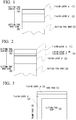
Fig. 1 is a schematic diagram representing an embodiment of a vertical section (a cross section perpendicular to a tool body) of a hard coating layer of a surface-coated cutting tool according to the present invention, in which a TiAlCN layer γ and a TiAlCN layer δ are not provided between a TiAlCN layer α on a tool surface side and a TiAlCN layer β on a tool body side. -
Fig. 2 is a schematic diagram representing another embodiment of a vertical section (a cross section perpendicular to a tool body) of a hard coating layer of a surface-coated cutting tool according to the present invention, in which a TiAlCN layer γ or a TiAlCN layer δ is provided between a TiAlCN layer α on a tool surface side and a TiAlCN layer β on a tool body side. -
Fig. 3 is a schematic diagram representing still another embodiment of a vertical section (a cross section perpendicular to a tool body) of a hard coating layer of a surface-coated cutting tool according to the present invention, in which a hard coating layer having a laminated structure of a TiAlCN layer α and a TiAlCN layer β are provided on a rake face and a TiAlCN layer β is provided on a flank face. - Hereinafter, a coated tool of the present invention will be described in more detail. In the descriptions of the present specification and Claims, when a numerical range is expressed by using "to", the range includes numerical values of an upper limit and a lower limit.
- As shown in
Fig. 1 , the coated tool to the present invention has a laminated structure having one TiAlCN layer α (1) containing 70 area% or more (an upper limit may be 100 area%) of crystal grains having a wurtzite type hexagonal structure of a complex nitride or a complex carbonitride of Ti and Al, on a tool surface side (S) and one TiAlCN layer β (2) containing 70 area% or more (an upper limit may be 100 area%) of crystal grains having a NaCl type face-centered cubic structure of a complex nitride or complex carbonitride of Ti and Al, on the tool body side (B). - The reason for adopting the laminated structure is that when the TiAlCN layer α (1) having good thermal crack resistance is disposed on the tool surface side (S) and the TiAlCN layer β (2) having good wear resistance is disposed on the tool body side (B), thermal cracks on a rake face (5) are prevented from occurring while maintaining the wear resistance in the flank face (6), and furthermore, the damage from the rake face (5) to the flank face (6) can be prevented from occurring, and excellent cutting performance can be exhibited for a long period of time even in high-speed intermittent cutting of cast iron or the like.
- Further, when both the TiAlCN layer α (1) and the TiAlCN layer β (2) contain Al, the adhesion between the layers can be improved. In addition, as shown in
Fig. 2 , as needed, in order to improve the adhesion between the TiAlCN layer α (1) and the TiAlCN layer β (2), it is preferable that either a TiAlCN layer γ having a NaCl type face-centered cubic structure or a TiAlCN layer δ having the same structure is provided between the two layers. - Hereinafter, each layer will be described in detail.
- The TiAlCN layer α (1) is a layer containing at least crystal grains of a complex nitride or a complex carbonitride of Ti and Al, the crystal grains having a wurtzite type hexagonal structure having excellent thermal crack resistance (thermal shock resistance), and is provided on the tool surface side (S).
- A composition of the TiAlCN layer α (1) is controlled such that when the composition is represented by Composition Formula: (Ti(i-xα)Alxα)(CyαN(1-yα)), an average content ratio xα of Al in a total amount of Ti and Al and an average content ratio yα of C in a total amount of C and N (here, xα and yα are atomic ratios) satisfy 0.70 ≤ xα ≤ 0.95 and 0.000 ≤ yα ≤ 0.010.
- The reason for setting the xα in the range is that when the xα is less than 0.70, the wurtzite type hexagonal structure is not stably formed and the thermal crack resistance is lowered, which are not preferable, and when xα is more than 0.95, the adhesion to the TiAlCN layer β (2) is lowered and the wear resistance is lowered, which are not preferable. Also, the reason for setting the yα in the range is that when the yα is in the range, lubricity is improved to alleviate impact during cutting and improve chipping resistance, and when the yα is out of the range, the adhesion to the TiAlCN layer β (2) is reduced.
- The average layer thickness La of the TiAlCN layer α (1) is preferably 0.5 µm to 10.0 µm. The reason for setting the range is that when the average layer thickness is less than 0.5 µm, the hard coating layer is worn out at an early stage even on the rake face (5), the effect of improving the thermal crack resistance is not exhibited, and when the average layer thickness is more than 10.0 µm, the crystal grains become coarse and the chipping resistance is lowered. The average layer thickness range is more preferably 1.0 µm to 3.0 µm.
- Area ratio of crystal grains having wurtzite type hexagonal structure in TiAlCN layer α:
The area ratio of the crystal grains having a wurtzite type hexagonal structure in the TiAlCN layer α (1) is 70 area% or more. When the area ratio is not 70 area% or more, the amount of the crystal grains having a wurtzite type hexagonal structure is not sufficient, and the thermal crack resistance and the chipping resistance are lowered. The area ratio is more preferably 85 area% or more, and may also be 100 area%. - The TiAlCN layer β (2) is a layer containing at least crystal grains of a complex nitride or a complex carbonitride of Ti and Al, the crystal grains having a NaCl type face-centered cubic structure having excellent wear resistance, and is provided on the tool body side (B).
- A composition of the TiAlCN layer β (2) is controlled such that when the composition is represented by Composition Formula: (Ti(1-xβ)Alxβ)(CyβN(1-yβ)), an average content ratio xβ of Al in a total amount of Ti and Al and an average content ratio yβ of C in a total amount of C and N (here, xβ and yβ are atomic ratios) satisfy 0.65 ≤ xβ ≤ 0.95 and 0.000 ≤ yβ ≤ 0.010.
- The reason for setting the xβ in the range is that when the xβ is less than 0.65, the hardness of the TiAlCN layer β (2) is reduced and the wear resistance is not sufficient, and when the xβ is more than 0.95, the Ti content ratio is relatively reduced, and thus it is likely to contain the crystal grains having a wurtzite type hexagonal structure to lead to decrease in the wear resistance, which is not preferable. Further, when the yβ is in the range, the adhesion between the TiAlCN layer β (2) and the tool body(3) or a lower layer to be described later is improved, the lubricity is improved to alleviate the impact during cutting, and the chipping resistance and fracturing resistance of the TiAlCN layer β (2) are improved. On the other hand, when the yβ is out of the range, the adhesion to the TiAlCN layer α (1) is lowered, which is not preferable.
- The average layer thickness Lβ of the TiAlCN layer β (2) is preferably 1.0 µm to 20.0 µm. The reason for setting the range is that when the average layer thickness is less than 1.0 µm, sufficient wear resistance cannot be ensured over a long-term use because the layer thickness is thin. On the other hand, when the average layer thickness is more than 20.0 µm, the crystal grains of the TiAlCN layer β (2) is easy to be coarsened and chipping is likely to occur, which is not preferable. The average layer thickness range is more preferably 5.0 µm to 12.0 µm.
- The area ratio of the crystal grains having a NaCl type face-centered cubic structure in the TiAlCN layer β (2) is 70 area% or more. When the area ratio is not 70 area% or more, the wear resistance is lowered, the flank face (6) is easily worn, and the life of the coated tool is reached at an early stage. The area ratio is more preferably 85 area% or more, and may also be 100 area%.
- The composition difference between the average content ratio xα of Al in the TiAlCN layer α (1) and the average content ratio xβ of Al in the TiAlCN layer β (2) is preferably |xα-xβ| ≤ 0.20, that is, -0.20 ≤ xα-xβ ≤ 0.20. When the difference is in the range, the adhesion between the TiAlCN layer α (1) and the TiAlCN layer β (2) is enhanced, and it becomes easy to prevent chipping after the occurrence of thermal cracks from occurring.
- In order to improve the adhesion between the TiAlCN layer α (1) and the TiAlCN layer β (2), it is preferable that a TiAlCN layer γ (4) having a NaCl type face-centered cubic structure is provided between the two layers.
- When a composition of the TiAlCN layer γ (4) is represented by Composition Formula: (Ti(1-xγ)Alxγ)(CyγN(1-yγ)), an average content ratio xγ of Al in a total amount of Ti and Al and an average content ratio and the average content ratio yγ of C in a total amount of C and N (here, x and yγ are atomic ratios) satisfy xα ≤ xγ ≤ xβ or xα ≤ xγ ≤ xβ, and are preferably 0.000 ≤ yα ≤ 0.010. When providing the TiAlCN layer γ (4) having the composition, an initial nucleation of the crystal grains of the TiAlCN layer α (1) is easily formed and a nucleation density can be raised, and adhesion between the TiAlCN layer α (1) and the TiAlCN layer β (2) can be enhanced to get higher chipping resistance.
- The average layer thickness of the TiAlCN layer γ is 0.1 to 1.0 µm. The reason for setting the range is that when the average layer thickness is less than 0.1 µm, the TiAlCN layer γ has too thin average layer thickness, and a region of the TiAlCN layer β (2) which is not sufficiently coated with the TiAlCN layer γ, and when the average layer thickness is more than 1.0 µm, the crystal grains of the TiAlCN layer γ become coarse, and the initial nucleation of the crystal grains of the TiAlCN layer α (1) is not sufficiently formed and the nucleation density is low. In either case, enhancement in the adhesion between the TiAlCN layer α (1) and the TiAlCN layer β (2) cannot be expected.
- When the xα and the xβ satisfy xα ≠ xβ, in order to enhance the adhesion between the TiAlCN layer α (1) and the TiAlCN layer β (2), it is further preferable that a TiAlCN layer δ having a NaCl type face-centered cubic structure is provided between the two layers, instead of the TiAlCN layer γ.
- When the TiAlCN layer δ is divided into two equal parts in a layer thickness direction of the TiAlCN layer δ, it is preferable that an average content ratio xδL of Al in a total amount of Ti and Al and an average content ratio yδL of C in a total amount of C and N (here, xδL and yδL are atomic ratios) when a composition of a region on the tool body side (B) is represented by Composition Formula: (Ti(1-xδL)AlxδL)(CyδLN(1-yδL)) and an average content ratio xδH of Al in a total amount of Ti and Al and an average content ratio yδH of C in a total amount of C and N (here, xδH and yδH are atomic ratios) when a composition of a region on the tool surface side (S) is represented by Composition Formula: (Ti(1-xδII)AlxδII)(CyδIIN(1-yδII)) satisfy xα ≤ xδH <xδL ≤ xβ or xβ ≤ xδL < xδH ≤ xα and 0.000 ≤ yδH ≤ 0.010 and 0.000 ≤ yδL ≤ 0.010.
- When specifying the composition as above, the adhesion between the TiAlCN layer β (2) and the TiAlCN layer δ (4) can further be enhanced by bringing the xβ in the TiAlCN layer β (2) closer to the xδL of the TiAlCN layer δ. In addition, the adhesion between the TiAlCN layer α (1) and the TiAlCN layer δ (4) can also be enhanced by bringing the xα in the TiAlCN layer α (1) and the xδH of the TiAlCN layer δ (4) close to each other, and the adhesion between the TiAlCN layer α (1) and the TiAlCN layer β (2) can be enhanced to get higher chipping resistance.
- The average layer thickness of the TiAlCN layer δ (4) is 0.1 to 1.0 µm. The reason for setting the range is that when the average layer thickness is less than 0.1 µm, the TiAlCN layer δ (4) has too thin average layer thickness, and a region of the TiAlCN layer β (2) which is not sufficiently coated with the TiAlCN layer δ (4), and when the average layer thickness is more than 1.0 µm, the crystal grains of the TiAlCN layer δ (4) become coarse, and the initial nucleation of the crystal grains of the TiAlCN layer α (1) is not sufficiently formed and the nucleation density is low. Accordingly, in either case, enhancement in the adhesion between the TiAlCN layer α (1) and the TiAlCN layer β (2) cannot be expected.
- As shown in
Fig. 3 , it is preferable that the hard coating layer having a laminated structure including the TiAlCN layer α (1) and the TiAlCN layer β (2) is provided on the rake face (5) and the TiAlCN layer β (2) is provided on the surface of the flank face (6). The TiAlCN layer α (1) may be provided on the flank face (6), but when the TiAlCN layer α (1) having low wear resistance does not exist on the surface of the flank face (6) that most rubs against a work material, it is possible to prevent the TiAlCN layer α (1) together with the TiAlCN layer β (2) from falling off, and the tool life is further prolonged. - The hard coating layer having the laminated structure of the present invention may include other layers. For example, when a lower layer having a Ti-compound layer which is formed of one or more layers among a carbide layer, a nitride layer, a carbonitride layer, a carbonic acid layer, and a oxycarbonitride layer of Ti, and has an average total layer thickness of 0.1 to 20.0 µm is provided adjacent to the tool body (3), along with the effects of the layers, it is possible to exhibit even better wear resistance and thermal stability.
- Here, when the average total layer thickness of the lower layer is less than 0.1 µm, the effect of the lower layer is not sufficiently exhibited. On the other hand, when the average total layer thickness is more than 20.0 µm, the crystal grains of the lower layer are likely to be coarsened and chipping is likely to occur.
- A boundary between TiAlCN layers of the TiAlCN layer α (1), the TiAlCN layer β (2), the TiAlCN layer γ (4), and the TiAlCN layer δ (4) is determined in a manner that: a vertical section (a cross section perpendicular to the tool body) obtained by polishing the hard coating layer is prepared using a focused ion beam device (FIB: Focused Ion Beam system), a cross section polisher (CP), and the like; in the vertical section, a quadrangle in which the vertical direction is the thickness of the entire hard coating layer and the transverse direction is 100 µm parallel to the tool body is set as a measurement area; and a crystal structure of each crystal grain is analyzed using an electron beam backscatter analysis device based on an electron beam backscatter diffraction image obtained by irradiating the measurement area with an electron beam having an acceleration voltage of 15 kV and an irradiation current of 1 nA at an incident angle of 70 degrees with a step of 0.01 µm.
- A point where there is an orientation difference of 5 degrees or more between adjacent measurement points (pixels) is defined as the grain boundary. However, a pixel that exists independently and has the orientation difference of 5 degrees or more from all adjacent pixels is not treated as a crystal grain, and one that is connected by 2 pixels or more is treated as the crystal grain.
- By determining each crystal grain and distinguishing the crystal structure thereof as above, each layer is specified, and an area ratio of the crystal grains having the wurtzite type hexagonal structure or the NaCl type face-centered cubic structure in each layer can be determined.
- When the boundary of each layer of the TiAlCN layers is defined, the average layer thickness can be determined between the boundary areas of the defined each layer, and an average content ratio (xα, xβ, xγ, xδL, and xδH) of Al in each layer can be determined irradiating the layer with an electron beam using an Auger electron spectroscopy and performing a plurality of line analyzes (for example, 5 or more lines) in the layer thickness direction, and averaging the analysis results obtained.
- Further, the average content ratio of C (ya, yβ, yγ, yδL, and yδH) of each layer can be determined for each layer by secondary ion mass spectrometry. That is, the content ratio in a depth direction is measured by alternately repeating the surface analysis using an ion beam and etching using a sputtered ion beam. Specifically, in each of the TiAlCN layers, an average value obtained by measuring at least 0.5 µm of length at a pitch of 0.1 µm or less is determined from the points where penetration occurs by 0.5 µm or more, and this operation is performed at 5 or more points to obtain the average content ratio of C in each layer.
- As the tool body (3), any base material known in the related art as the type of a tool body can be used as long as the material does not hinder the achievement of the objective of the present invention. For example, the tool body is preferably any one of a cemented carbide (such as a WC-based cemented carbide and cemented carbide containing Co in addition to WC and further containing carbonitrides such as Ti, Ta, and Nb), cermet (cermet containing TiC, TiN, TiCN, and the like as main components), ceramics (such as titanium carbide, silicon carbide, silicon nitride, aluminum nitride, and aluminum oxide), or a cBN sintered material.
- Each TiAlCN layer of the present invention can be obtained, for example, supplying two kinds of reaction gases including a gas group A and a gas group B having the following compositions, with a predetermined phase difference on the tool body or at least one or more layers of a carbide layer, a nitride layer, a carbonitride layer, a oxycarbide layer, and a oxycarbonitride layer of Ti on the tool body.
- As an example of the gas composition of the reaction gas is as follows, and % represents a % by volume (the sum of the gas group A and the gas group B is the whole).
- (1) Reaction gas α for forming TiAlCN layer α
- Gas group A: 5.0 to 10.0% of NH3, 3.0 to 5.0% of N2, 1.0 to 5.0% of Ar, and 50 to 60% of H2
- Gas group B: 0.70 to 1.20% of AlCl3, 0.10 to 0.30% of TiCl4, 3.0 to 12.0% of N2, 0.00 to 0.10% of HCl, 0.0 to 0.5% of C2H4, and H2 as a balance
- Reaction atmosphere pressure: 4.5 to 5.0 kPa
- Reaction atmosphere temperature: 750 to 950°C
- Supply cycle: 4.0 to 12.0 seconds
- Gas supply time per cycle: 0.20 to 0.70 seconds
- Phase difference between supply of gas group A and gas group B: 0.18 to 0.60 seconds
- (2) Reaction gas β for forming TiAlCN layer β
- Gas group A: 1.0 to 2.0% of NH3, 1.0 to 5.0% of Ar, and 50 to 60% of H2
- Gas group B: 0.60 to 1.40% of AlCl3 and 0.05 to 0.50% of TiCl4, 0.0 to 5.0% of N2, 0.0 to 0.5% of C2H4, and H2 as a balance
- Reaction atmosphere pressure: 4.5 to 5.0 kPa
- Reaction atmosphere temperature: 700 to 850°C
- Supply cycle: 4.0 to 12.0 seconds
- Gas supply time per cycle: 0.20 to 0.70 seconds
- Phase difference between supply of gas group A and gas group B: 0.18 to 0.60 seconds
- (3) Reaction gases γ and δ for forming TiAlCN layers γ and δ
- Gas group A: 3.0 to 4.0% of NH3, 1.0 to 2.0% of N2, 1.0 to 5.0% of Ar, and 50 to 60% of H2
- Gas group B: 0.6 to 1.2% of AlCl3 and 0.10 to 0.30% of TiCl4, 0.0 to 5.0% of N2, 0.0 to 0.5% of C2H4, and H2 as a balance
- Reaction atmosphere pressure: 4.5 to 5.0 kPa
- Reaction atmosphere temperature: 700 to 850°C
- Supply cycle: 4.0 to 12.0 seconds
- Gas supply time per cycle: 0.20 to 0.70 seconds
- Phase difference between supply of gas group A and gas group B: 0.18 to 0.60 seconds
- In the formation of the TiAlCN layer δ, a gas composition change is linear (gradient change) from the start of film formation to the end of film formation of the same layer, or the TiAlCN layer δ can be formed by fixing the composition for a certain period of time a plurality of times while changing the gas composition from the start of film formation to the end of film formation of the same layer.
- Here, as a specific example of the coated tool of the present invention, a coated tool applied to an insert cutting tool using the WC-based cemented carbide as the tool body will be described, but the same is applied to a case where the above-described other tool bodies are used as the tool body, and the same is applied to the case where it is applied to a drill, an end mill, or the like.
- As raw material powders, a WC powder, a TiC powder, a TaC powder, a NbC powder, a Cr3C2 powder, and a Co powder all having an average particle size of 1 to 3 µm were prepared. These raw material powders were blended to have a blending composition shown in Table 1, and a wax was further added and subjected to ball-mill mixing in acetone for 24 hours. The mixture was dried under a reduced pressure. Then, the mixture was press-molded into a green compact having a predetermined shape at a pressure of 98 MPa, and the press-molded body was vacuum-sintered in a vacuum of 5 Pa under conditions at a predetermined temperature in a range of 1370 to 1470°C for a holding time of 1 hour. After the sintering, tool bodies A to C made of the WC-based cemented carbide having an insert shape of ISO standard SEEN 1203 AFSN were produced.
- Next, a TiAlCN layer was formed on the surfaces of the tool bodies A to C by CVD using a CVD apparatus to obtain
coated tools 1 to 10 of the present invention shown in Table 7. - The film forming conditions are as shown in Tables 2 to 4, but are generally as follows. % of the gas composition is the % by volume (the sum of the gas group A and the gas group B is the whole (100% by volume)).
- (1) Reaction gas α for forming TiAlCN layer α (Table 2)
- Gas group A: 5.0 to 10.0% of NH3, 3.0 to 5.0% of N2, 1.0 to 5.0% of Ar, and 50 to 60% of H2
- Gas group B: 0.70 to 1.20% of AlCl3, 0.10 to 0.30% of TiCl4, 3.0 to 12.0% of N2, 0.00 to 0.10% of HCl, 0.0 to 0.5% of C2H4, and H2 as a balance
- Reaction atmosphere pressure: 4.5 to 5.0 kPa
- Reaction atmosphere temperature: 750 to 950°C
- Supply cycle: 4.0 to 12.0 seconds
- Gas supply time per cycle: 0.20 to 0.70 seconds
- Phase difference between supply of gas group A and gas group B: 0.18 to 0.60 seconds
- (2) Reaction gas β for forming TiAlCN layer β (Table 3)
- Gas group A: 1.0 to 2.0% of NH3, 1.0 to 5.0% of Ar, and 50 to 60% of H2
- Gas group B: 0.60 to 1.40% of AlCl3 and 0.05 to 0.50% of TiCl4, 0.0 to 5.0% of N2, 0.0 to 0.5% of C2H4, and H2 as a balance
- Reaction atmosphere pressure: 4.5 to 5.0 kPa
- Reaction atmosphere temperature: 700 to 850°C
- Supply cycle: 4.0 to 12.0 seconds
- Gas supply time per cycle: 0.20 to 0.70 seconds
- Phase difference between supply of gas group A and gas group B: 0.18 to 0.60 seconds
- (3) Reaction gases γ and δ for forming TiAlCN layers γ and δ (Table 4)
- Gas group A: 3.0 to 4.0% of NH3, 1.0 to 2.0% of N2, 1.0 to 5.0% of Ar, and 50 to 60% of H2
- Gas group B: 0.6 to 1.2% of AlCl3 and 0.10 to 0.30% of TiCl4, 0.0 to 5.0% of N2, 0.0 to 0.5% of C2H4, and H2 as a balance
- Reaction atmosphere pressure: 4.5 to 5.0 kPa
- Reaction atmosphere temperature: 700 to 850°C
- Supply cycle: 4.0 to 12.0 seconds
- Gas supply time per cycle: 0.20 to 0.70 seconds
- Phase difference between supply of gas group A and gas group B: 0.18 to 0.60 seconds
- As shown in Table 4, TiAlCN layer γ had no change in the gas composition, and in the formation of the TiAlCN layer δ, a gas composition change is L (gradient change) from the start of film formation to the end of film formation of the same layer, or S (stepwise change) of fixing the composition for a certain period of time a plurality of times while changing the gas composition from the start of film formation to the end of film formation of the same layer.
- Further, in the coated tool of the present invention in which the hard coating layer on the flank face is only the TiAlCN layer β, the TiAlCN layer α on the flank face is removed by polishing using an elastic grindstone.
- The
coated tools 4 to 6 and 8 to 10 of the present invention were formed to have the lower layer shown in Table 6 under the film forming conditions shown in Table 5. - For the objective of comparison, comparative
coated tools 1 to 10 shown in Table 7 were produced by film formation on the surfaces of the tool bodies A to C by a CVD apparatus under the conditions shown in Tables 2 to 4. - The comparative
coated tools 4 to 6 and 8 to 10 were formed to have the lower layer shown in Table 6 under the film forming conditions shown in Table 5. - For the
coated tools 1 to 10 of the present invention and the comparative coatedtools 1 to 10, the composition of each TiAlCN layer, the average layer thickness, the area ratio of the crystal grains of the wurtzite type hexagonal structure, and the area ratio of the crystal grains having the NaCl type face-centered cubic structure were determined using the above method, and the results thereof are shown in Table 7.[Table 1] Type Blending composition (% by mass) Co TiC TaC NbC Cr3C2 WC Tool body A 6.0 - 0.4 0.6 - Balance B 8.5 1.1 - - 0.3 Balance C 10 - - - 1.0 Balance [Table 2] Formation of TiAlCN layer α Gas composition of reaction gas α Reaction condition of reaction gas α Type of film formation step Formation symbol Composition of reaction gas group A (% by volume) Composition of reaction gas group B (% by volume) Gas group A Gas group B Phase difference between supply of gas group A and gas group B (Second) Reaction atmosphere Supply cycle (Second Supply time per cycle (Second) Supply cycle (Second ) Supply time per cycle (Second) I Pressure (kPa) Temperature (°C) NH3 N2 Ar H2 AlCl3 TiCl4 N2 HCl C2H4 H2 Step of present invention A 7.0 3.5 3.2 53 0.80 0.10 6.0 0.01 0.1 Balance 4.1 0.27 4.1 0.27 0.25 4.6 800 B 5.5 3.0 3.5 50 1.10 0.10 5.0 0.04 0.0 Balance 6.9 0.52 6.9 0.52 0.44 4.7 900 C 10.0 4.5 1.0 56 0.70 0.30 12.0 0.03 0.2 Balance 12.0 0.40 12.0 0.40 0.18 4.5 950 D 5.6 3.0 5.0 55 0.70 0.12 6.0 0.06 0.4 Balance 10.2 0.20 10.2 0.20 0.30 4.8 900 E 7.5 5.0 1.5 54 1.20 0.10 10.0 0.05 0.0 Balance 10.0 0.70 10.0 0.70 0.55 4.9 950 F 6.1 4.3 2.0 60 0.80 0.30 11.0 0.07 0.5 Balance 5.5 0.65 5.5 0.65 0.60 4.8 750 G 6.0 3.2 4.0 57 1.15 0.10 6.0 0.00 0.0 Balance 11.0 0.30 11.0 0.30 0.50 5.0 750 H 5.7 3.0 3.0 55 0.90 0.10 11.0 0.09 0.3 Balance 4.0 0.40 4.0 0.40 0.35 4.7 850 I 8.6 4.0 2.0 53 0.90 0.25 3.0 0.10 0.0 Balance 6.3 0.50 6.3 0.50 0.60 5.0 850 J 5.0 4.0 4.0 50 1.00 0.17 4.0 0.00 0.0 Balance 5.0 0.60 5.0 0.60 0.58 4.6 900 Step for comparison A' 10.0 2.0 1.0 35 1.50 0.10 3.0 1.00 0.1 Balance 4.1 0.27 4.1 0.27 0.25 4.6 800 B' 2.0 4.3 1.0 45 0.20 0.20 3.0 0.10 0.0 Balance 6.9 0.52 6.9 0.52 0.44 4.7 650 C' 3.0 2.0 3.0 58 0.60 0.20 3.0 2.00 5.0 Balance 12.0 0.40 12.0 0.40 0.18 4.5 850 D' 1.0 0.0 0.0 60 0.30 0.30 3.0 1.50 0.0 Balance 10.2 0.20 10.2 0.20 0.30 4.8 1000 E' 9.0 8.0 0.0 50 1.10 0.00 10.0 0.00 0.0 Balance 10.0 0.70 10.0 0.70 0.65 4.9 900 F' 4.0 2.0 2.3 57 0.80 0.30 4.0 0.00 0.4 Balance 5.5 0.65 5.5 0.65 0.70 4.8 800 G' 3.5 2.1 6.3 41 1.80 0.60 4.0 5.00 0.0 Balance 11.0 0.30 11.0 0.30 0.50 5.0 950 H' 3.0 2.0 4.1 55 0.90 0.90 1.5 2.10 0.4 Balance 4.0 0.40 4.0 0.40 0.35 4.7 700 I' 7.3 10.0 0.0 56 2.00 0.10 3.0 1.00 0.0 Balance 6.3 0.50 6.3 0.50 0.60 4.8 1050 J' 2.3 4.0 4.0 50 1.70 0.27 4.0 0.00 0.0 Balance 5.0 0.60 5.0 0.60 0.58 4.6 650 [Table 3] Formation of TiAlCN layer β Gas composition of reaction gas β Reaction condition of reaction gas β Type of film formation step Formation symbol Composition of reaction gas group A (% by volume) Composition of reaction gas group B (% by volume) Gas group A Gas group B Phase difference between supply of gas group A and gas group B (Second) Reaction atmosphere Supply cycle (Second) Supply time per cycle (Second) Supply cycle (Second) Supply time per cycle (Second) Pressure (kPa) Temperature (°C) NH3 Ar H2 AlCl3 TiCl4 N2 C2H 4 H2 Step of present invention A 1.0 4.3 58 0.65 0.30 1.8 0.0 Balance 4.1 0.27 4.1 0.27 0.25 4.6 700 B 1.8 1.3 52 1.00 0.20 0.5 0.1 Balance 6.9 0.52 6.9 0.52 0.44 4.7 700 C 1.2 3.6 54 0.88 0.05 1.8 0.1 Balance 12.0 0.40 12.0 0.40 0.18 4.5 800 D 1.6 4.7 56 0.95 0.10 3.9 0.0 Balance 10.2 0.20 10.2 0.20 0.30 4.8 850 E 1.8 5.0 53 0.95 0.50 2.8 0.3 Balance 10.0 0.70 10.0 0.70 0.55 4.9 700 F 1.9 3.2 60 0.90 0.20 0.0 0.2 Balance 5.5 0.65 5.5 0.65 0.60 4.8 750 G 2.0 1.0 50 0.80 0.35 3.6 0.0 Balance 11.0 0.30 11.0 0.30 0.50 5.0 750 H 1.4 1.5 55 0.60 0.07 5.0 0.0 Balance 4.0 0.40 4.0 0.40 0.35 4.7 850 I 1.2 2.6 52 1.40 0.30 4.0 0.1 Balance 6.3 0.50 6.3 0.50 0.60 5.0 800 J 1.3 3.3 53 0.75 0.30 4.5 0.2 Balance 5.0 0.60 5.0 0.60 0.58 4.6 800 Step for comparison A' 5.0 1.0 70 1.20 0.20 1.0 0.0 Balance 4.1 0.27 4.1 0.27 0.25 4.6 950 B' 1.0 3.0 55 0.30 0.20 1.0 0.0 Balance 6.9 0.52 6.9 0.52 0.44 6.0 750 C' 3.0 2.0 40 0.80 0.10 0.0 5.0 Balance 12.0 0.40 12.0 0.40 0.18 4.5 800 D' 6.0 0.0 30 2.00 0.20 2.0 0.0 Balance 10.2 0.20 10.2 0.20 0.30 4.8 900 E' 2.0 5.0 53 1.00 0.50 5.0 0.3 Balance 10.0 0.70 10.0 0.70 0.65 4.9 750 F' 3.0 1.0 45 0.00 0.70 1.0 0.0 Balance 5.5 0.65 5.5 0.65 0.70 4.8 950 G' 2.0 1.0 50 0.80 0.35 3.6 0.0 Balance 11.0 0.30 11.0 0.30 0.50 5.0 800 H' 2.0 1.2 53 0.60 0.60 0.0 0.0 Balance 4.0 0.40 4.0 0.40 0.35 4.7 800 I' 1.5 2.1 50 1.40 0.30 3.0 0.1 Balance 6.3 0.50 6.3 0.50 0.60 4.8 750 J' 1.3 3.3 53 0.75 0.30 4.5 0.2 Balance 5.0 0.60 5.0 0.60 0.58 4.6 800 [Table 4] Formation of TiAlCN layer γ or δ Gas composition of reaction gas γ or δ Reaction condition of reaction gas γ or δ Type of film formation step Formation symbol Composition of reaction gas group A (% by volume) Composition of reaction gas group B (% by volume) Change in gas composition * Gas group A Gas group B Phase difference between supply of gas group A and gas group B Reaction atmosphere Supply cycle (Second) Supply time per cycle (Second) Supply cycle (Second) Supply time per cycle (Second) Pressure (kPa) Temperature (°C) NH3 N2 Ar H2 AlCl3 TiCl4 N2 C2H4 H2 Step of present invention C 3.3 1.9 5.0 55 1.2 0.10 1.7 0.0 Balance None 12.0 0.40 12.0 0.40 0.18 4.5 850 D 3.0 1.0 3.5 51 0.8 0.10 1.5 0.3 Balance Balance L 10.2 0.20 10.2 0.20 0.30 4.8 850 3.5 2.0 2.5 60 0.7 0.10 1.6 0.0 E 4.0 1.5 1.0 58 0.9 0.30 1.3 0.5 Balance S 10.0 0.70 10.0 0.70 0.55 4.9 850 3.5 1.5 1.0 56 0.6 0.10 1.0 0.5 F 3.7 1.8 2.0 50 0.8 0.20 1.0 0.2 Balance None 5.5 0.65 5.5 0.65 0.60 4.8 750 I 3.5 1.2 4.0 52 1.1 0.25 2.0 0.5 Balance None 6.3 0.50 6.3 0.50 0.60 5.0 800 J 3.0 1.3 2.8 56 0.7 0.20 1.6 0.0 Balance Balance L 5.0 0.60 5.0 0.60 0.58 4.6 850 4.0 1.5 2.3 56 1.2 0.30 2.0 0.0 Step for comparison C' 2.0 1.0 0.0 66 0.9 0.10 3.0 0.5 Balance None 12.0 0.40 12.0 0.40 0.18 4.5 950 D' 8.0 1.0 6.5 50 0.8 0.10 3.0 0.0 Balance Balance L 10.2 0.20 10.2 0.20 0.30 4.8 850 1.0 1.0 3.4 66 0.7 0.10 2.0 0.0 E' 4.0 1.5 1.0 58 0.9 0.30 1.3 0.5 Balance S 10.0 0.70 10.0 0.70 0.65 4.9 850 3.5 1.5 1.0 56 0.6 0.10 1.0 0.5 F' 3.2 1.5 2.5 50 0.8 0.20 1.0 0.2 Balance None 5.5 0.65 5.5 0.65 0.70 4.8 750 I' 3.5 1.2 4.0 52 1.1 0.25 2.0 0.5 Balance None 6.3 0.50 6.3 0.50 0.60 5.0 800 J' 3.0 1.3 2.8 56 0.7 0.20 1.6 0.0 Balance Balance L 5.0 0.60 5.0 0.60 0.58 4.6 900 4.0 1.5 2.3 56 1.2 0.30 2.0 0.0 Note 1: L shows that a change of a gas composition is a gradient change and S shows that a change of a gas composition is a stepwise change.
Note 2: The gas composition in the upper row is a composition at the time of starting film formation and the gas composition in the lower row is a composition at the time of end of the film formation, when the change is the gradient change L
Note 3: The gas composition in the upper row is a composition at the first half of the film formation and the gas composition in the lower row is a composition at the second half of the film formation, when the change is the stepwise change S[Table 5] Constituent layer of hard coating layer Formation condition (Pressure represents kPa and temperature represents °C in reaction atmosphere) Type Formation symbol Reaction gas composition (% by volume) Reaction atmosphere Pressure Temperature TiAlCN layer TiAlCN TiAlCN See Tables 2 to 4 See Tables 2 to 4 Ti compound layer TiN TiN TiCl4:4.2%, N2:30.0%, H2: Balance 7.0 800 TiCN TiCN TiCl4:2.0%, CH3CH:0.7%, N2:10.0%, H2: Balance 7.0 800 [Table 6] Type Tool body symbol Hard coating layer (Numerical value in a represents an average layer thickness (µm) of the layer) Lower layer First laver Second layer Coated tool of present invention and Comparative coated tool 1 A - - 2 B - - 3 C - - 4 A TiN(0.1) - 5 B TiN(0.3) TiCN(5.0) 6 C TiN(0.5) TiCN(3.0) 7 A - - 8 B TiN(1.0) TiCN(3.0) 9 C TiN(0.5) TiCN(2.0) 10 A TiN(0.3) TiCN(3.0) 

- Next, the
coated tools 1 to 10 of the present invention and comparativecoated tools 1 to 10 were subjected to the following cutting test. - In a state where the various coated tools were clamped to the tip of an alloy steel cutter with a cutter diameter of 85 mm with a fixing jig, the following wet high-speed face milling and center cut cutting test for cast iron were performed and the width of flank wear of a cutting edge was measured. Table 8 shows the results of the cutting test. Since the comparative coated
tools 1 to 10 have reached the end of the life due to the occurrence of chipping, the time until the end of the life is shown. - Cutting test: Wet high-speed face milling and center cut cutting test
- Cutter diameter: 85 mm
- Work material: JIS/FCD700 Block material with a width of 60 mm and a length of 400 mm
- Rotation speed: 1124 min-1
- Cutting speed: 300 m/min
- Depth of cut: 3.0 mm
- Feed rate: 0.3 mm/tooth
- Cutting time: 5 minutes
- (Normal cutting speed is 200m/min)
- The cutting time (minute) until the end of the life of the comparative coated tool represents the cutting time until the end of the life due to the occurrence of chipping.
- As raw material powders, a WC powder, a TiC powder, a ZrC powder, a TaC powder, a NbC powder, a Cr3C2 powder, a TiN powder, and a Co powder all having an average particle size of 1 to 3 µm were prepared. These raw material powders were blended to have a blending composition shown in Table 9, and a wax was further added and subjected to ball-mill mixing in acetone for 24 hours. The mixture was dried under a reduced pressure. Thereafter, the mixture was press-molded into a green compact having a predetermined shape at a pressure of 98 MPa, and the green compact was vacuum-sintered in a vacuum of 5 Pa under conditions at a predetermined temperature in a range of 1370 to 1470°C for a holding time of 1 hour. After the sintering, tool bodies α to γ made of the WC-based cemented carbide having an insert shape of ISO standard CNMG 120412 were produced by subjecting to a honing of R: 0.07 mm to the cutting edge.
- Next, the TiAlCN layer α, the TiAlCN layer β, the TiAlCN layer γ, and the TiAlCN layer δ were formed on the surfaces of these tool body α to γ, by using a CVD apparatus under the conditions shown in Tables 2 to 4 in the same method as in Example 1 to obtain coated tools 11 to 20 of the present invention shown in Table 11.
- The coated tools 14 to 16, 18, and 19 of the present invention were formed to have the lower layer shown in Table 10 under the film forming conditions shown in Table 5.
- Also, as in the Example 1, for the objective of comparison, comparative coated tools 11 to 20 shown in Table 11 were produced by using the CVD method on the surfaces of the tool bodies α to γ under the conditions shown in Tables 2 to 4.
- The comparative coated tools 14 to 16, 18, and 19 were formed to have the lower layer shown in Table 10 under the forming conditions shown in Table 5.
- Also, as in Example 1, for the hard coating layers of the coated tools 11 to 20 of the present invention and the comparative coated tools 11 to 20, the composition of each TiAlCN layer, the average layer thickness, the area ratio of the crystal grains of the wurtzite type hexagonal structure, and the area ratio of the crystal grains having the NaCl type face-centered cubic structure were determined using the above method. The results thereof are shown in Table 11.
[Table 9] Type Blending composition (% by mass) Co TiC ZrC TaC NbC Cr3C2 TiN WC Tool body α 6.5 - 1.5 - 2.5 0.1 1.5 Balance β 7.5 2.4 - 4.0 0.5 - 1.0 Balance γ 6.0 - - - - - - Balance [Table 10] Type Tool body symbol Hard coating layer (Numerical value in a lower row represents an average layer thickness (µm) of the layer) Lower layer First layer Second layer Coated tool of present invention and Comparative coated tool 11 α - - 12 β - - 13 γ - - 14 α TiN (2.0) - 15 β TiN (0.5) TiCN (5.0) 16 γ TiN (1.0) TiCN (7.0) 17 α - - 18 β TiN (1.0) TiCN (7.0) 19 γ TiN (0.5) TiCN (20.0) 20 α - - 

- Next, In a state where the various coated tools were screwed to the tip of the alloy steel cutting tool with a fixing jig, the coated tools 11 to 20 of the present invention and the comparative coated tools 11 to 20 were subjected to dry high-speed intermittent cutting test shown below, and the width of flank wear of the cutting edge was measured. The results thereof are shown in Table 12. Since the comparative coated tools 11 to 20 have reached the end of the life due to the occurrence of chipping, the time until the end of the life is shown.
- Cutting test: Dry high-speed intermittent cutting
- Work material: JIS/FCD600 Round bar with 8 vertical grooves at equal intervals in a length direction
- Cutting speed: 350m/min
- Depth of cut: 3.0 mm
- Feed: 0.3 mm/rev
- Cutting time: 5 minutes
- The cutting time (minute) until the end of the life of the comparative coated tool represents the cutting time until the end of the life due to the occurrence of chipping.
- From the results shown in Tables 8 and 12, the hard coating layer of each of the
coated tool 1 to 20 of the present invention has excellent chipping resistance. Therefore, even when used for high-speed intermittent cutting of cast iron or the like, chipping does not occur and excellent wear resistance is exhibited over a long period of time. On the other hand, in the comparative coatedtools 1 to 20 which do not satisfy even one of the matters specified in the coated tool of the present invention, chipping occurs when used for the high-speed intermittent cutting of cast iron or the like, and the tool life has reached the end in a short time. - As described above, the coated tool of the present invention can be used as a coated tool for high-speed intermittent cutting of cast iron or the like, and also exhibits excellent wear resistance for a long period of time. Therefore, it is possible to fully satisfy the labor saving and energy saving of the cutting and the cost reduction.
-
- 1:
- TiAlCN layer a
- 2:
- TiAlCN layer β
- 3:
- Tool body
- 4:
- TiAlCN layer γ or TiAlCN layer δ
- 5:
- Rake face
- 6:
- Flank face
- S:
- Tool surface side
- B:
- Tool body side
| Type | width of flank wear (mm) | Type | *: Cutting time until end of life (Minute) | ||
| Coated tool of | 1 | 0.19 | Comparative | 1 | 3.8 |
| 2 | 0.18 | 2 | 3.0 | ||
| 3 | 0.17 | 3 | 4.3 | ||
| 4 | 0.15 | 4 | 4.3 | ||
| 5 | 0.16 | 5 | 4.2 | ||
| 6 | 0.12 | 6 | 2.8 | ||
| 7 | 0.18 | 7 | 3.2 | ||
| 8 | 0.17 | 8 | 3.0 | ||
| 9 | 0.11 | 9 | 4.6 | ||
| 10 | 0.10 | 10 | 4.8 | ||
| Type | width of flank wear (mm) | Type | *: Cutting time until end of life (Minute) | ||
| Coated tool of present invention | 11 | 0.18 | Comparative coated tool | 11 | 3.8 |
| 12 | 0.17 | 12 | 2.7 | ||
| 13 | 0.17 | 13 | 4.2 | ||
| 14 | 0.14 | 14 | 4.1 | ||
| 15 | 0.15 | 15 | 4.0 | ||
| 16 | 0.11 | 16 | 2.3 | ||
| 17 | 0.18 | 17 | 3.2 | ||
| 18 | 0.16 | 18 | 3.0 | ||
| 19 | 0.11 | 19 | 4.4 | ||
| 20 | 0.09 | 20 | 4.5 | ||
Claims (5)
- A surface-coated cutting tool comprising:a tool body; anda hard coating layer provided on a surface of the tool body, wherein(a) the hard coating layer has a laminated structure having one TiAlCN layer α containing 70 area% or more of crystal grains having a wurtzite type hexagonal structure of a complex nitride or a complex carbonitride of Ti and Al, on a tool surface side and one TiAlCN layer β containing 70 area% or more of crystal grains having a NaCl type face-centered cubic structure of a complex nitride or complex carbonitride of Ti and Al, on a tool body side,(b) when a composition of the TiAlCN layer α is represented by Composition Formula: (Ti(1-xα)Alxα)(CyαN(1-yα)), an average content ratio xα of Al in a total amount of Ti and Al and an average content ratio yα of C in a total amount of C and N (here, xα and yα are atomic ratios) satisfy 0.70 ≤ xα ≤ 0.95 and 0.000 ≤ yα ≤ 0.010,(c) when a composition of the TiAlCN layer β is represented by Composition Formula: (Ti(1-xβ)Alxβ)(CyβN(1-yβ)), an average content ratio xβ of Al in a total amount of Ti and Al and an average content ratio yβ of C in a total amount of C and N (here, xβ and yβ are atomic ratios) satisfy 0.65 ≤ xβ ≤ 0.95 and 0.000 ≤ yβ ≤ 0.010, and(d) when average layer thicknesses of the TiAlCN layer α and the TiAlCN layer β are defined as Lα and Lβ, the TiAlCN layer α and the TiAlCN layer β satisfy 0.5 µm ≤ Lα ≤ 10.0 µm and 1.0 µm ≤ Lβ ≤ 20.0 µm.
- The surface-coated cutting tool according to Claim 1, wherein a difference between the xα and the xβ satisfies |xα-xβ| ≤ 0.20.
- The surface-coated cutting tool according to Claim 1 or 2, wherein
a TiAlCN layer γ containing at least crystal grains having a NaCl type face-centered cubic structure of a complex nitride or a complex carbonitride of Ti and Al, exists between the TiAlCN layer α and the TiAlCN layer β,(a) when a composition of the TiAlCN layer γ is represented by Composition Formula: (Ti(1-xγ)Alxγ)(CyγN(1-yγ)), xγ satisfies xα ≤ xγ ≤ xβ or xα ≥ xγ ≥ xβ and yγ satisfies 0.000 ≤ yγ ≤ 0.010, regarding an average content ratio xγ of Al in a total amount of Ti and Al and an average content ratio yγ of C in a total amount of C and N (here, xγ and yγ are atomic ratios), and(b) when an average layer thickness of the TiAlCN layer γ is defined as Lγ, 0.1 µm ≤ Lγ ≤ 1.0 µm is satisfied. - The surface-coated cutting tool according to Claim 1 or 2, wherein
when the xα and the xβ satisfy xα ≠ xβ, a TiAlCN layer δ containing at least crystal grains having a NaCl type face-centered cubic structure of a complex nitride or a complex carbonitride of Ti and Al, exists between the TiAlCN layer α and the TiAlCN layer β,(a) in the TiAlCN layer δ, an average content ratio xδL of Al in a total amount of Ti and Al and an average content ratio yδL of C in a total amount of C and N (here, xδL and yδL are atomic ratios) when a composition of a region on the tool body side of the TiAlCN layer δ divided into two equal parts in a layer thickness direction of the TiAlCN layer δ is represented by Composition Formula: (Ti(1-xδL)AlxδL)(CyδLN(1-yδL)) and an average content ratio xδH of Al in a total amount of Ti and Al and an average content ratio yδH of C in a total amount of C and N (here, xδH and yδH are atomic ratios) when a composition of a region on the tool surface side of the TiAlCN layer δ divided into two equal parts in the layer thickness direction of the TiAlCN layer δ is represented by Composition Formula: (Ti(1-xδII)AlxδII)(CyδIIN(1-yδII)) satisfy xα ≤ xδH <xδL ≤ xβ or xβ ≤ xδL < xδH ≤ xα and 0.000 ≤ yδH ≤ 0.010 and 0.000 ≤ yδL ≤ 0.010, and(b) when an average layer thickness of the TiAlCN layer δ is defined as Lδ, the TiAlCN layer δ satisfies 0.1 µm ≤ Lδ ≤ 1.0 µm. - The surface-coated cutting tool according to any one of Claims 1 to 4,wherein the hard coating layer having the laminated structure of the TiAlCN layer α and the TiAlCN layer β is provided on the rake face of the surface-coated cutting tool, andthe TiAlCN layer β is provided on a surface of a flank face.
Applications Claiming Priority (3)
| Application Number | Priority Date | Filing Date | Title |
|---|---|---|---|
| JP2018243963 | 2018-12-27 | ||
| JP2019227056A JP7520286B2 (en) | 2018-12-27 | 2019-12-17 | Surface-coated cutting tools |
| PCT/JP2019/051161 WO2020138304A1 (en) | 2018-12-27 | 2019-12-26 | Surface-coated cutting tool |
Publications (2)
| Publication Number | Publication Date |
|---|---|
| EP3903974A1 true EP3903974A1 (en) | 2021-11-03 |
| EP3903974A4 EP3903974A4 (en) | 2022-06-15 |
Family
ID=71129522
Family Applications (1)
| Application Number | Title | Priority Date | Filing Date |
|---|---|---|---|
| EP19902513.1A Pending EP3903974A4 (en) | 2018-12-27 | 2019-12-26 | Surface-coated cutting tool |
Country Status (3)
| Country | Link |
|---|---|
| US (1) | US12162079B2 (en) |
| EP (1) | EP3903974A4 (en) |
| WO (1) | WO2020138304A1 (en) |
Families Citing this family (4)
| Publication number | Priority date | Publication date | Assignee | Title |
|---|---|---|---|---|
| JP7319600B6 (en) * | 2021-12-10 | 2023-08-18 | 株式会社タンガロイ | coated cutting tools |
| CN115537772B (en) * | 2022-09-20 | 2024-04-26 | 株洲钻石切削刀具股份有限公司 | Coated cutting tool |
| EP4678315A1 (en) * | 2023-03-07 | 2026-01-14 | Mitsubishi Materials Corporation | Surface-coated cutting tool |
| WO2025132516A1 (en) * | 2023-12-20 | 2025-06-26 | Walter Ag | A coated cutting tool |
Family Cites Families (23)
| Publication number | Priority date | Publication date | Assignee | Title |
|---|---|---|---|---|
| JP2001341008A (en) | 2000-06-02 | 2001-12-11 | Hitachi Tool Engineering Ltd | Titanium nitride-aluminum film coated tool and manufacturing method therefor |
| JP2005271133A (en) | 2004-03-24 | 2005-10-06 | Sumitomo Electric Hardmetal Corp | Coated cutting tool |
| DE102007000512B3 (en) | 2007-10-16 | 2009-01-29 | Fraunhofer-Gesellschaft zur Förderung der angewandten Forschung e.V. | Hard-coated body with a multi-layer system for tools and components such as drills, millers and indexable inserts, comprises a bonding layer applied on the body, a single- or multi-phase hard layer, and a phase gradient layer |
| DE102008013965A1 (en) | 2008-03-12 | 2009-09-17 | Kennametal Inc. | Hard material coated body |
| US8277958B2 (en) * | 2009-10-02 | 2012-10-02 | Kennametal Inc. | Aluminum titanium nitride coating and method of making same |
| DE102009046667B4 (en) * | 2009-11-12 | 2016-01-28 | Fraunhofer-Gesellschaft zur Förderung der angewandten Forschung e.V. | Coated bodies of metal, hardmetal, cermet or ceramic, and methods of coating such bodies |
| JP5710008B2 (en) * | 2011-08-30 | 2015-04-30 | 京セラ株式会社 | Cutting tools |
| WO2014002948A1 (en) * | 2012-06-29 | 2014-01-03 | 住友電工ハードメタル株式会社 | Cutting tool for surface coating |
| JP6090063B2 (en) * | 2012-08-28 | 2017-03-08 | 三菱マテリアル株式会社 | Surface coated cutting tool |
| JP6206133B2 (en) | 2012-11-30 | 2017-10-04 | 三菱マテリアル株式会社 | Surface coated cutting tool |
| JP6268530B2 (en) | 2013-04-01 | 2018-01-31 | 三菱マテリアル株式会社 | Surface coated cutting tool with excellent chipping resistance due to hard coating layer |
| DE102013104254A1 (en) | 2013-04-26 | 2014-10-30 | Walter Ag | Tool with CVD coating |
| JP2015066644A (en) * | 2013-09-30 | 2015-04-13 | 三菱マテリアル株式会社 | Surface-coated cutting tool with hard coating layer showing excellent wear resistance and chipping resistance in high-speed cutting work |
| JP6238131B2 (en) | 2013-12-26 | 2017-11-29 | 住友電工ハードメタル株式会社 | Coating and cutting tools |
| JP6344602B2 (en) | 2014-06-17 | 2018-06-20 | 住友電工ハードメタル株式会社 | Hard coating, cutting tool, and manufacturing method of hard coating |
| EP3000913B1 (en) | 2014-09-26 | 2020-07-29 | Walter Ag | Coated cutting tool insert with MT-CVD TiCN on TiAI(C,N) |
| JP6120229B2 (en) * | 2015-01-14 | 2017-04-26 | 住友電工ハードメタル株式会社 | Hard coating, cutting tool, and manufacturing method of hard coating |
| JP6590255B2 (en) | 2015-03-13 | 2019-10-16 | 三菱マテリアル株式会社 | Surface coated cutting tool with excellent chipping resistance due to hard coating layer |
| JP6507959B2 (en) * | 2015-09-14 | 2019-05-08 | 三菱マテリアル株式会社 | Surface coated cutting tool exhibiting excellent chipping resistance with hard coating layer |
| JP6638936B2 (en) | 2016-01-13 | 2020-02-05 | 住友電工ハードメタル株式会社 | Surface coated cutting tool and method of manufacturing the same |
| JP2019511378A (en) * | 2016-03-31 | 2019-04-25 | ヴァルター アーゲー | Coated cutting tools with h-AlN and Ti1-xAlxCyNz layers |
| WO2018008554A1 (en) | 2016-07-07 | 2018-01-11 | 三菱日立ツール株式会社 | Hard coating, hard coating-covered tool, and methods for producing both |
| JP6781954B2 (en) | 2017-01-25 | 2020-11-11 | 三菱マテリアル株式会社 | Surface coating cutting tool with excellent chipping resistance and peeling resistance with a hard coating layer |
-
2019
- 2019-12-26 EP EP19902513.1A patent/EP3903974A4/en active Pending
- 2019-12-26 US US17/417,631 patent/US12162079B2/en active Active
- 2019-12-26 WO PCT/JP2019/051161 patent/WO2020138304A1/en not_active Ceased
Also Published As
| Publication number | Publication date |
|---|---|
| WO2020138304A1 (en) | 2020-07-02 |
| US20220111446A1 (en) | 2022-04-14 |
| EP3903974A4 (en) | 2022-06-15 |
| US12162079B2 (en) | 2024-12-10 |
Similar Documents
| Publication | Publication Date | Title |
|---|---|---|
| EP2823923B1 (en) | Surface-coated cutting tool having therein hard coating layer capable of exhibiting excellent chipping resistance during high-speed intermittent cutting work | |
| JP4518260B2 (en) | Surface-coated cermet cutting tool whose hard coating layer exhibits excellent chipping resistance in high-speed intermittent cutting | |
| EP2085500B1 (en) | Surface-coated cutting tool with hard coating layer having excellent abrasion resistance | |
| EP3135412B1 (en) | Surface-coated cutting tool having a hard coating layer that exhibits excellent chipping resistance | |
| EP3150309B1 (en) | Surface-coated cutting tool | |
| EP3202515A1 (en) | Surface-coated cutting tool having excellent chip resistance | |
| EP2982466A1 (en) | Surface-coated cutting tool | |
| EP2891536A1 (en) | Surface-coated cutting tool | |
| EP3199275A1 (en) | Surface-coated cutting tool in which hard coating layer exhibits excellent chipping resistance | |
| EP3150310B1 (en) | Surface-coated cutting tool comprising hard coating layer that exhibits excellent chipping resistance | |
| EP3456858B1 (en) | Coated cutting tool | |
| US12162079B2 (en) | Surface-coated cutting tool | |
| JP2016168669A (en) | Surface coated cutting tool with hard-coated layer exhibiting superior chipping resistance | |
| EP3225338A1 (en) | Surface-coated cutting tool | |
| EP3213840A1 (en) | Surface-coated cutting tool | |
| JP6905807B2 (en) | Surface coating cutting tool with excellent chipping resistance and peeling resistance with a hard coating layer | |
| EP3858524A1 (en) | Surface coated cutting tool having hard coating layer exhibiting excellent chipping resistance | |
| JP2020055097A (en) | Surface-coated cutting tool with hard coating layer for excellent chipping resistance | |
| US12350742B2 (en) | Surface-coated cutting tool | |
| JP6850998B2 (en) | Surface coating cutting tool with a hard coating layer that exhibits excellent wear resistance and chipping resistance | |
| CN113474111B (en) | Surface-coated cutting tool | |
| JP7137149B2 (en) | A surface-coated cutting tool with a hard coating layer that exhibits excellent chipping resistance | |
| JP6957824B2 (en) | Surface coating cutting tool with excellent chipping resistance and wear resistance with a hard coating layer | |
| JP2020146820A (en) | Cutting tool with excellent chipping resistance due to the hard coating layer | |
| JP7610181B2 (en) | Surface-coated cutting tools |
Legal Events
| Date | Code | Title | Description |
|---|---|---|---|
| STAA | Information on the status of an ep patent application or granted ep patent |
Free format text: STATUS: THE INTERNATIONAL PUBLICATION HAS BEEN MADE |
|
| PUAI | Public reference made under article 153(3) epc to a published international application that has entered the european phase |
Free format text: ORIGINAL CODE: 0009012 |
|
| STAA | Information on the status of an ep patent application or granted ep patent |
Free format text: STATUS: REQUEST FOR EXAMINATION WAS MADE |
|
| 17P | Request for examination filed |
Effective date: 20210726 |
|
| AK | Designated contracting states |
Kind code of ref document: A1 Designated state(s): AL AT BE BG CH CY CZ DE DK EE ES FI FR GB GR HR HU IE IS IT LI LT LU LV MC MK MT NL NO PL PT RO RS SE SI SK SM TR |
|
| DAV | Request for validation of the european patent (deleted) | ||
| DAX | Request for extension of the european patent (deleted) | ||
| A4 | Supplementary search report drawn up and despatched |
Effective date: 20220518 |
|
| RIC1 | Information provided on ipc code assigned before grant |
Ipc: B23B 27/14 20060101ALN20220512BHEP Ipc: C23C 16/34 20060101ALI20220512BHEP Ipc: C23C 30/00 20060101ALI20220512BHEP Ipc: C23C 28/04 20060101ALI20220512BHEP Ipc: C23C 16/36 20060101AFI20220512BHEP |