EP3903973B1 - Metal cutting tool with nozzle for providing coolant fluid to a cutting edge - Google Patents
Metal cutting tool with nozzle for providing coolant fluid to a cutting edge Download PDFInfo
- Publication number
- EP3903973B1 EP3903973B1 EP20171564.6A EP20171564A EP3903973B1 EP 3903973 B1 EP3903973 B1 EP 3903973B1 EP 20171564 A EP20171564 A EP 20171564A EP 3903973 B1 EP3903973 B1 EP 3903973B1
- Authority
- EP
- European Patent Office
- Prior art keywords
- nozzle
- coolant
- outlet
- cutting tool
- internal
- Prior art date
- Legal status (The legal status is an assumption and is not a legal conclusion. Google has not performed a legal analysis and makes no representation as to the accuracy of the status listed.)
- Active
Links
Images



Classifications
-
- B—PERFORMING OPERATIONS; TRANSPORTING
- B23—MACHINE TOOLS; METAL-WORKING NOT OTHERWISE PROVIDED FOR
- B23B—TURNING; BORING
- B23B27/00—Tools for turning or boring machines; Tools of a similar kind in general; Accessories therefor
- B23B27/10—Cutting tools with special provision for cooling
-
- B—PERFORMING OPERATIONS; TRANSPORTING
- B05—SPRAYING OR ATOMISING IN GENERAL; APPLYING FLUENT MATERIALS TO SURFACES, IN GENERAL
- B05B—SPRAYING APPARATUS; ATOMISING APPARATUS; NOZZLES
- B05B1/00—Nozzles, spray heads or other outlets, with or without auxiliary devices such as valves, heating means
- B05B1/14—Nozzles, spray heads or other outlets, with or without auxiliary devices such as valves, heating means with multiple outlet openings; with strainers in or outside the outlet opening
-
- B—PERFORMING OPERATIONS; TRANSPORTING
- B05—SPRAYING OR ATOMISING IN GENERAL; APPLYING FLUENT MATERIALS TO SURFACES, IN GENERAL
- B05B—SPRAYING APPARATUS; ATOMISING APPARATUS; NOZZLES
- B05B1/00—Nozzles, spray heads or other outlets, with or without auxiliary devices such as valves, heating means
- B05B1/34—Nozzles, spray heads or other outlets, with or without auxiliary devices such as valves, heating means designed to influence the nature of flow of the liquid or other fluent material, e.g. to produce swirl
-
- B—PERFORMING OPERATIONS; TRANSPORTING
- B05—SPRAYING OR ATOMISING IN GENERAL; APPLYING FLUENT MATERIALS TO SURFACES, IN GENERAL
- B05B—SPRAYING APPARATUS; ATOMISING APPARATUS; NOZZLES
- B05B9/00—Spraying apparatus for discharge of liquids or other fluent material, without essentially mixing with gas or vapour
- B05B9/03—Spraying apparatus for discharge of liquids or other fluent material, without essentially mixing with gas or vapour characterised by means for supplying liquid or other fluent material
- B05B9/035—Spraying apparatus for discharge of liquids or other fluent material, without essentially mixing with gas or vapour characterised by means for supplying liquid or other fluent material to several spraying apparatus
-
- B—PERFORMING OPERATIONS; TRANSPORTING
- B23—MACHINE TOOLS; METAL-WORKING NOT OTHERWISE PROVIDED FOR
- B23B—TURNING; BORING
- B23B27/00—Tools for turning or boring machines; Tools of a similar kind in general; Accessories therefor
- B23B27/14—Cutting tools of which the bits or tips or cutting inserts are of special material
- B23B27/16—Cutting tools of which the bits or tips or cutting inserts are of special material with exchangeable cutting bits or cutting inserts, e.g. able to be clamped
- B23B27/1625—Cutting tools of which the bits or tips or cutting inserts are of special material with exchangeable cutting bits or cutting inserts, e.g. able to be clamped with plate-like cutting inserts of special shape clamped by a clamping member acting almost perpendicularly on the chip-forming plane
-
- B—PERFORMING OPERATIONS; TRANSPORTING
- B23—MACHINE TOOLS; METAL-WORKING NOT OTHERWISE PROVIDED FOR
- B23C—MILLING
- B23C5/00—Milling-cutters
- B23C5/28—Features relating to lubricating or cooling
-
- B—PERFORMING OPERATIONS; TRANSPORTING
- B23—MACHINE TOOLS; METAL-WORKING NOT OTHERWISE PROVIDED FOR
- B23B—TURNING; BORING
- B23B2250/00—Compensating adverse effects during turning, boring or drilling
- B23B2250/12—Cooling and lubrication
-
- B—PERFORMING OPERATIONS; TRANSPORTING
- B23—MACHINE TOOLS; METAL-WORKING NOT OTHERWISE PROVIDED FOR
- B23B—TURNING; BORING
- B23B5/00—Turning-machines or devices specially adapted for particular work; Accessories specially adapted therefor
- B23B5/28—Turning-machines or devices specially adapted for particular work; Accessories specially adapted therefor for turning wheels or wheel sets or cranks thereon, i.e. wheel lathes
-
- Y—GENERAL TAGGING OF NEW TECHNOLOGICAL DEVELOPMENTS; GENERAL TAGGING OF CROSS-SECTIONAL TECHNOLOGIES SPANNING OVER SEVERAL SECTIONS OF THE IPC; TECHNICAL SUBJECTS COVERED BY FORMER USPC CROSS-REFERENCE ART COLLECTIONS [XRACs] AND DIGESTS
- Y02—TECHNOLOGIES OR APPLICATIONS FOR MITIGATION OR ADAPTATION AGAINST CLIMATE CHANGE
- Y02P—CLIMATE CHANGE MITIGATION TECHNOLOGIES IN THE PRODUCTION OR PROCESSING OF GOODS
- Y02P70/00—Climate change mitigation technologies in the production process for final industrial or consumer products
- Y02P70/10—Greenhouse gas [GHG] capture, material saving, heat recovery or other energy efficient measures, e.g. motor control, characterised by manufacturing processes, e.g. for rolling metal or metal working
Definitions
- the present invention relates to a nozzle for providing coolant fluid to a cutting edge of a metal cutting tool and to such a metal cutting tool.
- coolant fluid could be delivered as close to the cutting edge as possible.
- a number of cooling systems are available on the market today where coolant fluid delivery is supplied through the tool holder and coolant nozzles at high pressure, e.g. EP 3167985 A1 .
- US2011/305531A , EP1080811A , WO2017/179972A and US2010/196105A which discloses the preamble of claim 1, disclose related prior art.
- the object of the present invention is achieved by the subject-matter of claim 1.
- the plenum chamber By introducing a plenum chamber into the nozzle where the total cross-sectional area of the inlet openings is larger than the total cross-sectional area of the outlet openings, the plenum chamber will be filled with coolant fluid which will increase the fluid pressure in the subsequent internal outlet channels and thereby also at the coolant outlets.
- coolant fluid By providing coolant fluid with an increased pressure towards the cutting edge, the chip breaking properties of the coolant fluid will increase, which will contribute to reducing the friction between the chip and the tool and thereby reducing the heat load on the tool.
- nozzle represents a unit, preferably a removable unit, for delivering coolant fluid to the cutting edge, preferably as close as possible to the cutting edge.
- a nozzle can for example be realized in form of a clamp or inducer.
- coolant fluid represents a fluid, either in liquid or gaseous form, for improving the cutting conditions and also the tool life. This type of fluid is also commonly designated as “coolant”, “cutting fluid”, “cutting oil”, or “lubrication fluid”.
- the plenum chamber is an internal volume of any geometrical shape that could be filled with coolant fluid in order to build up a fluid pressure, such as a "chamber”, “cavity”, “container” or “reservoir”.
- the inlet openings can have any geometric shape and are adapted to connect the inlet channels with the plenum chamber.
- the outlet openings can have any geometric shape and are adapted to connect the outlet channels with the plenum chamber.
- the cross-sectional area represents an area perpendicular to the flow direction measured at the inner wall of the inlet and outlet openings.
- the at least one outlet opening is fully located in a plane P, and the coolant outlet is located in a plane Q, wherein the plane P is parallel with the plane Q.
- the planes Q and P are arranged at an acute angle to each other.
- the direction of the ejected coolant fluid can be arranged to an optimum.
- the at least one internal coolant outlet channel is linear with a constant cross-sectional area A2 i .
- the outlet coolant channel By having a linear outlet coolant channel with a constant cross-sectional area corresponding to the cross-sectional area of the corresponding outlet opening, the outlet coolant channel will have a minimum impact on the ejected coolant fluid, which will contribute to maintaining the high pressure of the coolant fluid at the coolant outlet.
- the at least one outlet coolant channel has a cone-shape, i.e. the diameter of the at least one outlet coolant channel decreases as it goes from the plenum chamber towards the coolant outlet.
- the at least one internal outlet coolant channel has a length L out , wherein 0,5 mm ⁇ L out ⁇ 2,0 mm.
- a shorter outlet coolant channel will decrease the channels impact on the pressure.
- a longer channel than 2,0 mm will have a too large impact on the pressure of the coolant and is therefore not desirable.
- a shorter outlet channel than 0,5 mm will have a negative impact to the nozzle's strength at its outermost portion and is therefore not desirable.
- a high ratio between the total inlet opening cross-sectional area and the total outlet opening cross-sectional area will increase the amount of fluid in the plenum chamber and thus also the fluid pressure in the outlet coolant channels.
- a lower ratio than 1,3 will not give rise to the preferred increase of fluid pressure.
- a higher ratio than 56,3 will have a negative impact on the strength of the plenum chamber due to the lack of solid material.
- 1,5 mm 2 ⁇ A1 i ⁇ 15,0 mm 2 1,5 mm 2 ⁇ A1 i ⁇ 15,0 mm 2 .
- a smaller cross-sectional area than 1,5 mm 2 of the at least one inlet opening will result in that not enough coolant fluid can be provided to the cutting edge in order to achieve the preferred coolant effect as the corresponding outlet opening becomes too small since the ratio discussed above needs to be maintained.
- a larger cross-sectional area of the at least one inlet opening will have a negative impact on the strength of the plenum chamber due to the lack of solid material.
- the plenum chamber has an internal volume V, wherein 40 mm 3 ⁇ V ⁇ 420 mm 3 .
- a smaller internal volume than 40 mm 3 will not be able to create the amount of fluid pressure needed to achieve the preferred coolant effect.
- a higher internal volume than 420 mm 3 will have a negative impact on the strength of the nozzle due to the lack of solid material.
- the nozzle comprises at least two internal outlet coolant channels.
- the coolant fluid can be provided to a larger part of the cutting edge.
- the nozzle comprises at least two plenum chambers, wherein each plenum chamber comprises
- the ejected coolant fluid can be controlled to different pressures on different parts of the cutting edge, resulting in a more adaptable cooling system.
- the object of the present invention is achieved by means of a metal cutting tool as defined in claim 1.
- the metal cutting tool is preferably a turning tool, but can also be any other type of metal cutting tool e.g. a milling cutter.
- the cutting insert may be a cubic boron nitride cutting insert, a cemented carbide cutting insert, a cermet cutting insert, or a ceramic cutting insert, depending on application.
- the nozzle is a removable nozzle attached to the tool holder body. By having a removable nozzle attached to the tool, the nozzle can be easily changed if necessary.
- the nozzle is a clamp pressing against a part of the cutting insert. Such nozzle achieves that the number of components in the tool can be decreased since there is no need for a separate clamp to hold the insert in the tool holder body.
- Figure 1 illustrates a metal cutting tool (1).
- the metal cutting tool (1) comprises a tool holder body (2), a cutting insert (5) mounted in the tool holder body (2), and a nozzle (10) for providing coolant fluid to a cutting edge of the metal cutting tool (1).
- the metal cutting tool (1) according to this embodiment is a turning tool.
- FIG. 2 illustrates a side view of the nozzle (10).
- the nozzle (10) comprises an internal inlet coolant channel (16 11 ) connected to a coolant inlet (18) and an internal outlet coolant channel (17 11 ), with a length L out , connected to a coolant outlet (19 11 ) for ejecting coolant fluid towards a cutting edge of the metal cutting tool.
- the nozzle (10) further comprises a plenum chamber (20 1 ) connecting the internal inlet coolant channel (16 11 ) and internal outlet coolant channel (17 11 ).
- the outlet coolant channel (17 11 ) is connecting to the plenum chamber (20 1 ) in a plane Q and the coolant outlet (19 11 ) is located in a plane P.
- the plane Q is parallel with the plane P.
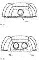
- Figure 3A illustrates a front view of a nozzle (10).
- the nozzle (10) comprises one coolant outlet (19 11 ) for ejecting the coolant fluid towards a cutting edge of the metal cutting tool.
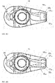
- Figure 4A illustrates a top view of a nozzle (10).
- the nozzle (10) comprises one internal inlet coolant channel (16 11 ) connecting to a coolant inlet (18) and one plenum chamber (20 1 ).
- the nozzle (10) further comprises one internal outlet coolant channel (17 11 ) connecting to a coolant outlet (19 11 ) and the plenum chamber (20 1 ).
- the nozzle (10) further comprises a bore (15) for a fastening element, e.g. a screw, for fastening the nozzle (10) to the tool holder body (2).
- a fastening element e.g. a screw
- Figure 3B illustrates a front view of a nozzle (10) according to a second embodiment.
- the nozzle (10) comprises two coolant outlets (19 11 ; 19 12 ) for ejecting the coolant fluid towards a cutting edge of the metal cutting tool.
- Figure 4B illustrates a top view of a nozzle (10).
- the nozzle (10) comprises two internal inlet coolant channels (16 11 ; 16 12 ) connecting to a coolant inlet (18) and one plenum chamber (20 1 ).
- the nozzle (10) further comprises two internal outlet coolant channels (17 11 ; 17 12 ) connecting to two coolant outlets (19 11 ; 19 12 ) and the plenum chamber (20 1 ).
- the nozzle (10) further comprises a bore (15) for a fastening element, e.g. a screw, for fastening the nozzle (10) to the tool holder body (2).
- a fastening element e.g. a screw
- FIG. 5 illustrates schematically the plenum chamber (20 1 ).
- the plenum chamber (20 1 ) has an internal volume V and comprises a first inlet opening (21 11 ) having a cross-sectional area A1 1 , and a second inlet opening (21 12 ) having a cross-sectional area A1 2 .
- the plenum chamber (20 1 ) further comprises a first outlet opening (22 11 ) having a cross-sectional area A2 1 , and a second outlet opening (22 12 ) having a cross-sectional area A2 2 .
- the plenum chamber (20 1 ) is illustrated as a rectangular block, and the inlet openings (21 11 ; 21 12 ) and the outlet openings (22 11 ; 22 12 ) as circular openings.
- the inlet openings (21 11 ; 21 12 ) and the outlet openings (22 11 ; 22 12 ) could be given, such as for example a spherical plenum chamber with square shaped inlet openings and triangular outlet openings.
- Figure 4C illustrates a top view of a nozzle (10).
- the nozzle (10) comprises one internal inlet coolant channel (16 11 ) connecting to a coolant inlet (18) and one plenum chamber (20 1 ).
- the nozzle (10) further comprises two internal outlet coolant channels (17 11 ; 17 12 ) connecting to two coolant outlets (19 11 ; 19 12 ) and the plenum chamber (20 1 ).
- the nozzle (10) further comprises a bore (15) for a fastening element, e.g. a screw, for fastening the nozzle (10) to the tool holder body (2).
- a fastening element e.g. a screw
- Figure 4D illustrates a top view of a nozzle (10) according to an embodiment of the invention.
- the nozzle (10) comprises a first internal inlet coolant channel (16 11 ) connecting to a coolant inlet (18) and a first plenum chamber (20 1 ).
- the nozzle (10) further comprises a second internal inlet coolant channel (16 21 ) connecting to a coolant inlet (18) and a second plenum chamber (20 2 ). Further, the nozzle (10) comprises a first internal outlet coolant channel (17 11 ) connecting to a coolant outlet (19 11 ) and the first plenum chamber (20 1 ), and a second internal outlet coolant channel (17 21 ) connecting to a coolant outlet (19 21 ) and the second plenum chamber (20 2 ).
- the nozzle (10) further comprises a bore (15) for a fastening element, e.g. a screw, for fastening the nozzle (10) to the tool holder body (2).
- the two internal inlet coolant channels (16 11 ; 16 12 ; 16 21 ) connects to the same coolant inlet (18). However, they could also connect to different coolant inlets.
Landscapes
- Engineering & Computer Science (AREA)
- Mechanical Engineering (AREA)
- Cutting Tools, Boring Holders, And Turrets (AREA)
Description
- The present invention relates to a nozzle for providing coolant fluid to a cutting edge of a metal cutting tool and to such a metal cutting tool.
- In some metal cutting applications, very high temperatures are generated which results in a high heat load on the cutting tool which leads to a decreased lifetime of the tool.
- In order to decrease the temperature and thereby increasing the lifetime of the tool, coolant fluid could be delivered as close to the cutting edge as possible. A number of cooling systems are available on the market today where coolant fluid delivery is supplied through the tool holder and coolant nozzles at high pressure, e.g.
EP 3167985 A1 . AlsoUS2011/305531A ,EP1080811A ,WO2017/179972A andUS2010/196105A which discloses the preamble ofclaim 1, disclose related prior art. - However, in some applications, a problem with the existing systems is that they are unsatisfactory in their ability to reduce the heat load of the cutting edge and thereby increase the lifetime of the cutting tool.
- It is an object to the present invention to overcome, or at least partially overcome, said problem by introducing a nozzle for providing coolant fluid to a cutting edge of a metal cutting tool, and such a metal cutting tool, where the coolant effect is increased.
- The object of the present invention is achieved by the subject-matter of
claim 1. - By introducing a plenum chamber into the nozzle where the total cross-sectional area of the inlet openings is larger than the total cross-sectional area of the outlet openings, the plenum chamber will be filled with coolant fluid which will increase the fluid pressure in the subsequent internal outlet channels and thereby also at the coolant outlets. By providing coolant fluid with an increased pressure towards the cutting edge, the chip breaking properties of the coolant fluid will increase, which will contribute to reducing the friction between the chip and the tool and thereby reducing the heat load on the tool.
- The term "nozzle" represents a unit, preferably a removable unit, for delivering coolant fluid to the cutting edge, preferably as close as possible to the cutting edge. A nozzle can for example be realized in form of a clamp or inducer.
- The term "coolant fluid" represents a fluid, either in liquid or gaseous form, for improving the cutting conditions and also the tool life. This type of fluid is also commonly designated as "coolant", "cutting fluid", "cutting oil", or "lubrication fluid".
- The plenum chamber is is an internal volume of any geometrical shape that could be filled with coolant fluid in order to build up a fluid pressure, such as a "chamber", "cavity", "container" or "reservoir".
- The inlet openings can have any geometric shape and are adapted to connect the inlet channels with the plenum chamber.
- The outlet openings can have any geometric shape and are adapted to connect the outlet channels with the plenum chamber.
- According to at least one embodiment, the cross-sectional area represents an area perpendicular to the flow direction measured at the inner wall of the inlet and outlet openings.
- According to one embodiment, the at least one outlet opening is fully located in a plane P, and the coolant outlet is located in a plane Q, wherein the plane P is parallel with the plane Q. By having the outlet openings parallel with the coolant outlets, the outlet coolant channels will have a minimum impact on the ejected coolant fluid which will contribute to maintaining the high pressure of the coolant fluid at the coolant outlets.
- According to another embodiment, the planes Q and P are arranged at an acute angle to each other. By having this type of orientation the direction of the ejected coolant fluid can be arranged to an optimum.
- According to one embodiment, the at least one internal coolant outlet channel is linear with a constant cross-sectional area A2i.
- By having a linear outlet coolant channel with a constant cross-sectional area corresponding to the cross-sectional area of the corresponding outlet opening, the outlet coolant channel will have a minimum impact on the ejected coolant fluid, which will contribute to maintaining the high pressure of the coolant fluid at the coolant outlet.
- According to another embodiment, the at least one outlet coolant channel has a cone-shape, i.e. the diameter of the at least one outlet coolant channel decreases as it goes from the plenum chamber towards the coolant outlet. By having this cone-shaped outlet coolant channel, the fluid pressure in the outlet coolant channel can be further increased.
- According to one embodiment, the at least one internal outlet coolant channel has a length Lout, wherein 0,5 mm ≤ Lout ≤ 2,0 mm. A shorter outlet coolant channel will decrease the channels impact on the pressure. In some applications, a longer channel than 2,0 mm will have a too large impact on the pressure of the coolant and is therefore not desirable. In some applications, a shorter outlet channel than 0,5 mm will have a negative impact to the nozzle's strength at its outermost portion and is therefore not desirable.
- According to one embodiment, the relation between the total inlet opening cross-sectional area and the total outlet opening cross-sectional area is

- A high ratio between the total inlet opening cross-sectional area and the total outlet opening cross-sectional area will increase the amount of fluid in the plenum chamber and thus also the fluid pressure in the outlet coolant channels. In some applications, a lower ratio than 1,3 will not give rise to the preferred increase of fluid pressure. In some applications, a higher ratio than 56,3 will have a negative impact on the strength of the plenum chamber due to the lack of solid material.
- According to one embodiment, 1,5 mm2 ≤ A1i ≤ 15,0 mm2. In some applications, a smaller cross-sectional area than 1,5 mm2 of the at least one inlet opening will result in that not enough coolant fluid can be provided to the cutting edge in order to achieve the preferred coolant effect as the corresponding outlet opening becomes too small since the ratio discussed above needs to be maintained. In some applications, a larger cross-sectional area of the at least one inlet opening will have a negative impact on the strength of the plenum chamber due to the lack of solid material. According to one embodiment, the plenum chamber has an internal volume V, wherein 40 mm3 ≤ V ≤ 420 mm3. In some applications, a smaller internal volume than 40 mm3 will not be able to create the amount of fluid pressure needed to achieve the preferred coolant effect. In some applications, a higher internal volume than 420 mm3 will have a negative impact on the strength of the nozzle due to the lack of solid material.
- According to one embodiment, the nozzle comprises at least two internal outlet coolant channels. By having a plurality of outlet coolant channels, the coolant fluid can be provided to a larger part of the cutting edge.
- The nozzle comprises at least two plenum chambers, wherein each plenum chamber comprises
- at least one inlet opening connecting the plenum chamber with at least one internal inlet coolant channel, and
- at least one outlet opening connecting the plenum chamber with at least one internal outlet coolant channel.
- By having a plurality of plenum chambers, the ejected coolant fluid can be controlled to different pressures on different parts of the cutting edge, resulting in a more adaptable cooling system.
- The object of the present invention is achieved by means of a metal cutting tool as defined in
claim 1. - The metal cutting tool is preferably a turning tool, but can also be any other type of metal cutting tool e.g. a milling cutter.
- The cutting insert may be a cubic boron nitride cutting insert, a cemented carbide cutting insert, a cermet cutting insert, or a ceramic cutting insert, depending on application.
- According to one embodiment, the nozzle is a removable nozzle attached to the tool holder body. By having a removable nozzle attached to the tool, the nozzle can be easily changed if necessary.
- The nozzle is a clamp pressing against a part of the cutting insert. Such nozzle achieves that the number of components in the tool can be decreased since there is no need for a separate clamp to hold the insert in the tool holder body.
- The following
figures 1,2 ,3A,3B ,4A,4B ,4C ,5 are not according to the invention and are present for illustration purposes only. -
Fig. 1 is a perspective view of a metal cutting tool, -
Fig. 2 is a side view of a nozzle, -
Fig. 3A is a front view of a nozzle, -
Fig. 3B is a front view of a nozzle, -
Fig. 4A is a top view of a nozzle, -
Fig. 4B is a top view of a nozzle, -
Fig. 4C is a top view of a nozzle, -
Fig. 4D is a top view of a nozzle according to an embodiment of the invention, -
Fig. 5 is a schematic view of the plenum chamber in the nozzle as illustrated infig 4B . - The may, however, be embodied in many different forms and should not be construed as limited to the embodiment set forth herein; rather, these embodiments are provided by way of example so that the disclosure will be thorough and complete, and will fully convey the scope of the invention to those skilled in the art. Like reference numbers refer to like elements throughout. The elements illustrated in the drawings are not necessary according to scale. Some elements might have been enlarged in order to clearly illustrate those elements.
-
Figure 1 illustrates a metal cutting tool (1). The metal cutting tool (1) comprises a tool holder body (2), a cutting insert (5) mounted in the tool holder body (2), and a nozzle (10) for providing coolant fluid to a cutting edge of the metal cutting tool (1). The metal cutting tool (1) according to this embodiment is a turning tool. -
Figure 2 illustrates a side view of the nozzle (10). The nozzle (10) comprises an internal inlet coolant channel (1611) connected to a coolant inlet (18) and an internal outlet coolant channel (1711), with a length Lout, connected to a coolant outlet (1911) for ejecting coolant fluid towards a cutting edge of the metal cutting tool. The nozzle (10) further comprises a plenum chamber (201) connecting the internal inlet coolant channel (1611) and internal outlet coolant channel (1711). The outlet coolant channel (1711) is connecting to the plenum chamber (201) in a plane Q and the coolant outlet (1911) is located in a plane P. In the illustrated embodiment the plane Q is parallel with the plane P. -
Figure 3A illustrates a front view of a nozzle (10). The nozzle (10) comprises one coolant outlet (1911) for ejecting the coolant fluid towards a cutting edge of the metal cutting tool. -
Figure 4A illustrates a top view of a nozzle (10). The nozzle (10) comprises one internal inlet coolant channel (1611) connecting to a coolant inlet (18) and one plenum chamber (201). The nozzle (10) further comprises one internal outlet coolant channel (1711) connecting to a coolant outlet (1911) and the plenum chamber (201). The nozzle (10) further comprises a bore (15) for a fastening element, e.g. a screw, for fastening the nozzle (10) to the tool holder body (2). - In the following, alternative illustrations will be described, focusing on differenting features.
-
Figure 3B illustrates a front view of a nozzle (10) according to a second embodiment. The nozzle (10) comprises two coolant outlets (1911; 1912) for ejecting the coolant fluid towards a cutting edge of the metal cutting tool. -
Figure 4B illustrates a top view of a nozzle (10). The nozzle (10) comprises two internal inlet coolant channels (1611; 1612) connecting to a coolant inlet (18) and one plenum chamber (201). The nozzle (10) further comprises two internal outlet coolant channels (1711; 1712) connecting to two coolant outlets (1911; 1912) and the plenum chamber (201). The nozzle (10) further comprises a bore (15) for a fastening element, e.g. a screw, for fastening the nozzle (10) to the tool holder body (2). -
Figure 5 illustrates schematically the plenum chamber (201). The plenum chamber (201) has an internal volume V and comprises a first inlet opening (2111) having a cross-sectional area A11, and a second inlet opening (2112) having a cross-sectional area A12. The plenum chamber (201) further comprises a first outlet opening (2211) having a cross-sectional area A21, and a second outlet opening (2212) having a cross-sectional area A22. - In
figure 5 , the plenum chamber (201) is illustrated as a rectangular block, and the inlet openings (2111; 2112) and the outlet openings (2211; 2212) as circular openings. However, in other embodiments, other geometrical shapes could be given, such as for example a spherical plenum chamber with square shaped inlet openings and triangular outlet openings. -
Figure 4C illustrates a top view of a nozzle (10). The nozzle (10) comprises one internal inlet coolant channel (1611) connecting to a coolant inlet (18) and one plenum chamber (201). The nozzle (10) further comprises two internal outlet coolant channels (1711; 1712) connecting to two coolant outlets (1911; 1912) and the plenum chamber (201). The nozzle (10) further comprises a bore (15) for a fastening element, e.g. a screw, for fastening the nozzle (10) to the tool holder body (2). -
Figure 4D illustrates a top view of a nozzle (10) according to an embodiment of the invention. In this embodiment, the nozzle (10) comprises a first internal inlet coolant channel (1611) connecting to a coolant inlet (18) and a first plenum chamber (201). - The nozzle (10) further comprises a second internal inlet coolant channel (1621) connecting to a coolant inlet (18) and a second plenum chamber (202). Further, the nozzle (10) comprises a first internal outlet coolant channel (1711) connecting to a coolant outlet (1911) and the first plenum chamber (201), and a second internal outlet coolant channel (1721) connecting to a coolant outlet (1921) and the second plenum chamber (202). The nozzle (10) further comprises a bore (15) for a fastening element, e.g. a screw, for fastening the nozzle (10) to the tool holder body (2).
- In some illustrations the two internal inlet coolant channels (1611; 1612; 1621) connects to the same coolant inlet (18). However, they could also connect to different coolant inlets.
Claims (9)
- A metal cutting tool (1), comprising- a tool holder body (2);- a cutting insert (5) mounted in the tool holder body (2); and- a nozzle (10) for providing coolant fluid to a cutting edge of a metal cutting tool (1), and being attached to the tool holder body (2), wherein the nozzle (10) is a clamp pressing against a part of the cutting insert; wherein the nozzle (10) comprises- at least one internal inlet coolant channel (161i; 162i),- at least one internal outlet coolant channel (1721i; 172i), wherein- the at least one internal inlet coolant channel (161i; 162i) is connected to a coolant inlet (18), and- the at least one internal outlet coolant channel (171i; 172i) is connected to a coolant outlet (191i; 192i) for directing the coolant fluid to the cutting edge,characterized in that the nozzle (10) further comprises- at least two plenum chambers (201; 202), wherein each plenum chamber (201; 202) comprises- at least one inlet opening (211i; 212i) connecting the at least one internal inlet coolant channel (161i; 162i) and the plenum chamber (201; 202), and- at least one outlet opening (221i; 222i) connecting the at least one internal outlet coolant channel (171i; 172i) and the plenum chamber (201; 202), wherein- each of the at least one inlet openings (211i; 212i) have a cross-sectional area A1i, and- each of the at least one outlet openings (221i; 222i) have a cross-sectional area A2i, wherein-

- The metal cutting tool (1) according to claim 1, wherein- the at least one outlet opening (221i; 222i) is located in a plane P, and- the coolant outlet (191i; 192i) is located in a plane Q, wherein- the plane P is parallel with the plane Q.
- The metal cutting tool (1) according to any of the proceeding claims, wherein- the at least one internal outlet coolant channel (171i; 172i) is linear with a constant cross-sectional area A2i.
- The metal cutting tool (1) according to any of the proceeding claims, wherein- the at least one internal outlet coolant channel (171i; 172i) has a length Lout, wherein 0,5 mm ≤ Lout ≤ 2,0 mm.
- The metal cutting tool (1) according to any of the proceeding claims, wherein

- The metal cutting tool (1) according to any of the proceeding claims, wherein 1,5 mm2 ≤ A1i ≤ 15,0 mm2.
- The metal cutting tool (1) according to any of the proceeding claims, wherein- the plenum chamber (201; 202) has an internal volume V, wherein 40 mm3 ≤ V ≤ 420 mm3.
- The metal cutting tool (1) according to any of the proceeding claims, wherein- the nozzle comprises at least two internal outlet coolant channels (171i; 172i).
- The metal cutting tool (1) according to any of the proceeding claims, wherein- the nozzle (10) is a removable nozzle attached to the tool holder body (2).
Priority Applications (4)
| Application Number | Priority Date | Filing Date | Title |
|---|---|---|---|
| EP20171564.6A EP3903973B1 (en) | 2020-04-27 | 2020-04-27 | Metal cutting tool with nozzle for providing coolant fluid to a cutting edge |
| PCT/EP2021/060083 WO2021219417A1 (en) | 2020-04-27 | 2021-04-19 | A nozzle for providing coolant fluid to a cutting edge of a metal cutting tool and a metal cutting tool |
| US17/921,493 US12440898B2 (en) | 2020-04-27 | 2021-04-19 | Nozzle for providing coolant fluid to a cutting edge of a metal cutting tool and a metal cutting tool |
| CN202180030470.0A CN115461177B (en) | 2020-04-27 | 2021-04-19 | Nozzle for supplying coolant fluid to cutting edge of metal cutting tool and metal cutting tool |
Applications Claiming Priority (1)
| Application Number | Priority Date | Filing Date | Title |
|---|---|---|---|
| EP20171564.6A EP3903973B1 (en) | 2020-04-27 | 2020-04-27 | Metal cutting tool with nozzle for providing coolant fluid to a cutting edge |
Publications (2)
| Publication Number | Publication Date |
|---|---|
| EP3903973A1 EP3903973A1 (en) | 2021-11-03 |
| EP3903973B1 true EP3903973B1 (en) | 2022-12-21 |
Family
ID=70470883
Family Applications (1)
| Application Number | Title | Priority Date | Filing Date |
|---|---|---|---|
| EP20171564.6A Active EP3903973B1 (en) | 2020-04-27 | 2020-04-27 | Metal cutting tool with nozzle for providing coolant fluid to a cutting edge |
Country Status (4)
| Country | Link |
|---|---|
| US (1) | US12440898B2 (en) |
| EP (1) | EP3903973B1 (en) |
| CN (1) | CN115461177B (en) |
| WO (1) | WO2021219417A1 (en) |
Cited By (1)
| Publication number | Priority date | Publication date | Assignee | Title |
|---|---|---|---|---|
| EP4480610A1 (en) | 2023-06-22 | 2024-12-25 | Seco Tools Ab | A metal cutting tool comprising a coolant channel |
Families Citing this family (3)
| Publication number | Priority date | Publication date | Assignee | Title |
|---|---|---|---|---|
| EP3903973B1 (en) * | 2020-04-27 | 2022-12-21 | Seco Tools Ab | Metal cutting tool with nozzle for providing coolant fluid to a cutting edge |
| CN115569759B (en) * | 2022-12-09 | 2023-02-03 | 华北理工大学 | Foldable injection device |
| US20250128333A1 (en) * | 2023-10-20 | 2025-04-24 | Kennametal Inc. | Through coolant clamps for tool holders |
Family Cites Families (53)
| Publication number | Priority date | Publication date | Assignee | Title |
|---|---|---|---|---|
| US522588A (en) * | 1894-07-10 | Means for lubricating cutting-edges of tools | ||
| US160161A (en) * | 1875-02-23 | Improvement in turning-tools for metal | ||
| US4848198A (en) * | 1988-04-21 | 1989-07-18 | Kennametal Inc. | Chip breaking tool holder |
| FR2713117B1 (en) * | 1993-12-01 | 1996-01-05 | Snecma | Method for machining parts of titanium or titanium alloys and coolant flange for such machining. |
| SE514938C2 (en) * | 1999-09-02 | 2001-05-21 | Sandvik Ab | Cutting Tools |
| SE0100652L (en) | 2001-02-27 | 2002-08-28 | Sandvik Ab | Process for chip separating machining and cutting tool for chip separating machining |
| US6652200B2 (en) * | 2001-11-01 | 2003-11-25 | Rolf H. Kraemer | Tool holder with coolant system |
| US7582004B2 (en) * | 2003-07-11 | 2009-09-01 | United Technologies Corporation | Coolant nozzle |
| SE530579C2 (en) * | 2006-11-28 | 2008-07-08 | Sandvik Intellectual Property | Tools and basic body for multi-channel chip separation machining |
| SE530581C2 (en) * | 2006-11-28 | 2008-07-08 | Sandvik Intellectual Property | Chip separation tool and basic body comprising two channels for a fluid |
| IL197095A (en) * | 2009-02-17 | 2013-02-28 | Iscar Ltd | Cutting tool having a retractable nozzle |
| DE102009060046A1 (en) * | 2009-12-21 | 2011-06-22 | Aleit GmbH, 35239 | System for fastening tool holder and shaper tool, has cooling lubricating medium groove, where cooling lubricating medium in operative position is passed from groove through hole and discharged on operative position through injector |
| IL206283A0 (en) * | 2010-06-10 | 2010-11-30 | Iscar Ltd | Cutting tool and nozzle therefor |
| IL206537A (en) * | 2010-06-22 | 2013-04-30 | Iscar Ltd | Cutting tool having a coolant supply |
| US8734062B2 (en) * | 2010-09-02 | 2014-05-27 | Kennametal Inc. | Cutting insert assembly and components thereof |
| US8388268B2 (en) * | 2011-03-07 | 2013-03-05 | Kennametal Inc. | Cutting assembly |
| DE202011101852U1 (en) * | 2011-06-14 | 2012-09-19 | Hartmetall-Werkzeugfabrik Paul Horn Gmbh | cutter |
| US8827598B2 (en) * | 2011-11-22 | 2014-09-09 | Kennametal Inc. | Cutting assembly with enhanced coolant delivery |
| US8696259B2 (en) * | 2012-02-02 | 2014-04-15 | Iscar, Ltd. | Tool holder having set screw for clamping a cutting insert therein |
| WO2014001447A1 (en) * | 2012-06-28 | 2014-01-03 | Ceramtec Gmbh | Tool for machining |
| US9434011B2 (en) * | 2013-01-25 | 2016-09-06 | Kennametal Inc. | Coolant spray nozzle and cutter with coolant spray nozzle |
| EP2789415B1 (en) * | 2013-04-09 | 2022-06-08 | Seco Tools Ab | Toolholder with clamp having fluid flow passages, and tool including such a toolholder |
| US9427807B2 (en) * | 2013-05-13 | 2016-08-30 | Dennis P. Flolo | Clamp to hold a cutting insert on a tool holder |
| US9511421B2 (en) * | 2013-06-14 | 2016-12-06 | Kennametal Inc. | Cutting tool assembly having clamp assembly comprising a clamp and a coolant plate |
| EP2873477A3 (en) * | 2013-11-14 | 2015-12-23 | Sandvik Tooling France | Cartridge for a grooving tool holder, corresponding grooving tool holder, kit and assembly thereof |
| US9387537B2 (en) * | 2014-03-28 | 2016-07-12 | Kennametal Inc. | Wedge clamp with fluid port |
| US9586263B2 (en) * | 2014-06-05 | 2017-03-07 | Kennametal Inc | Tool holder having improved internal coolant delivery |
| US10007246B2 (en) * | 2014-12-02 | 2018-06-26 | Caterpillar Inc. | Machining tool utilizing a supercritical coolant |
| DE102014119295B4 (en) * | 2014-12-19 | 2023-08-10 | Kennametal Inc. | Tool holder for a cutting insert and method for manufacturing the tool holder |
| CN204430302U (en) | 2015-01-19 | 2015-07-01 | 乐清市南方硬质合金有限公司 | GR3 cutter |
| US10596634B2 (en) * | 2015-06-30 | 2020-03-24 | Seco Tools Ab | Cutting tool with a nozzle with a coolant channel |
| EP3112063B1 (en) | 2015-06-30 | 2023-08-09 | Seco Tools Ab | A cutting tool |
| EP3408048B1 (en) * | 2016-01-29 | 2020-03-11 | Seco Tools Ab | A cutting tool |
| NL2016590B1 (en) * | 2016-04-12 | 2017-11-01 | Van Langh Holding B V | Cooling system and machining device. |
| JP2018027605A (en) * | 2016-08-19 | 2018-02-22 | 住友電工ハードメタル株式会社 | Cutting plate and cutting tool |
| DE112017004162B4 (en) * | 2016-08-22 | 2024-11-14 | Kyocera Corporation | Cutting tool holder, cutting tool and method of manufacturing a machined product using the same |
| EP3219421A1 (en) * | 2016-09-09 | 2017-09-20 | Seco Tools Ab | Toolholders with fluid supply conduits for supercritical co2 |
| EP3330024B1 (en) | 2016-12-01 | 2021-04-28 | Seco Tools Ab | Cutting tool having an anvil with curved passage and method for making such a cutting tool |
| US11890684B2 (en) * | 2016-12-01 | 2024-02-06 | Seco Tools Ab | Anvil with curved passage for cutting tool |
| DE112018000493B4 (en) * | 2017-01-24 | 2025-01-02 | Kyocera Corporation | Cutting tool and method of producing a machined product |
| US10300532B2 (en) * | 2017-06-26 | 2019-05-28 | Kennametal Inc. | Clamp for tool holder |
| TWI640376B (en) * | 2017-06-30 | 2018-11-11 | Hsien-Jen Huang | Improved structure of the tool holder |
| EP3659732B1 (en) * | 2017-07-27 | 2023-07-05 | Sumitomo Electric Hardmetal Corp. | Cutting tool holder |
| CN111372708A (en) * | 2017-11-28 | 2020-07-03 | 京瓷株式会社 | Cutting tool and method for manufacturing cut product |
| US10730115B2 (en) * | 2017-11-29 | 2020-08-04 | Iscar, Ltd. | Cutting tool fastener having internal fluid channel and spherical head abutment surface |
| US20190247926A1 (en) * | 2018-02-14 | 2019-08-15 | Kennametal Inc. | Cutting insert with internal coolant passageways |
| EP3624972B1 (en) * | 2018-04-30 | 2021-01-06 | Hartmetall-Werkzeugfabrik Paul Horn GmbH | Tool for machining a workpiece |
| FI3693110T3 (en) * | 2018-05-29 | 2023-03-20 | Ceram Gmbh | Tool system |
| EP3623083B1 (en) * | 2018-09-11 | 2022-11-09 | Walter Ag | Turning tool |
| US11541499B2 (en) * | 2020-01-22 | 2023-01-03 | Kennametal Inc. | Indexable milling cutter with precise coolant streams |
| US11590587B2 (en) * | 2020-04-16 | 2023-02-28 | Allied Machine & Engineering Corporation | Drill systems with coolant delivery arrangements and methods |
| EP3903973B1 (en) * | 2020-04-27 | 2022-12-21 | Seco Tools Ab | Metal cutting tool with nozzle for providing coolant fluid to a cutting edge |
| US12202050B2 (en) * | 2021-12-29 | 2025-01-21 | Kennametal Inc. | Turning toolholder with enhanced coolant delivery system |
-
2020
- 2020-04-27 EP EP20171564.6A patent/EP3903973B1/en active Active
-
2021
- 2021-04-19 WO PCT/EP2021/060083 patent/WO2021219417A1/en not_active Ceased
- 2021-04-19 CN CN202180030470.0A patent/CN115461177B/en active Active
- 2021-04-19 US US17/921,493 patent/US12440898B2/en active Active
Cited By (1)
| Publication number | Priority date | Publication date | Assignee | Title |
|---|---|---|---|---|
| EP4480610A1 (en) | 2023-06-22 | 2024-12-25 | Seco Tools Ab | A metal cutting tool comprising a coolant channel |
Also Published As
| Publication number | Publication date |
|---|---|
| CN115461177A (en) | 2022-12-09 |
| CN115461177B (en) | 2026-01-27 |
| WO2021219417A1 (en) | 2021-11-04 |
| EP3903973A1 (en) | 2021-11-03 |
| US20230191498A1 (en) | 2023-06-22 |
| US12440898B2 (en) | 2025-10-14 |
Similar Documents
| Publication | Publication Date | Title |
|---|---|---|
| EP3903973B1 (en) | Metal cutting tool with nozzle for providing coolant fluid to a cutting edge | |
| EP2596886B2 (en) | Cutting assembly | |
| US6045300A (en) | Tool holder with integral coolant passage and replaceable nozzle | |
| CN109661288B (en) | Cutting tool with coolant chamber having an integrally formed coolant deflecting portion and body | |
| US7997832B2 (en) | Milling cutter and milling insert with coolant delivery | |
| EP2117753B1 (en) | Milling cutter and milling insert with core and coolant delivery | |
| KR101614568B1 (en) | Removable insert-type cutting instrument | |
| US8696253B2 (en) | Cutting tool and shaped coolant outlet therefor | |
| US12502743B2 (en) | Tooling assembly with internal coolant passages for machines | |
| EP0211652A1 (en) | Method and apparatus for machining | |
| WO2008088628A1 (en) | Milling cutter and milling insert with coolant delivery | |
| WO2019220528A1 (en) | Cutting insert and milling tool | |
| CN115734831A (en) | Lightweight tool holder and cutting tool with coolant cavity having varying cross-sectional area | |
| US20060162415A1 (en) | Method and device for producing a hard metal tool | |
| JP7183916B2 (en) | Head member for grooving tool and grooving tool | |
| WO2018016412A1 (en) | Cutting tool | |
| EP3858522A1 (en) | A cutting insert for a cutting tool | |
| CN117817431A (en) | Cutting tool having a nozzle with multiple integrated fluid outlets | |
| EP4549061A1 (en) | Through coolant clamps for tool holders | |
| EP4454791A1 (en) | A toolholder and a cutting tool comprising such a toolholder | |
| CN215509022U (en) | Cutting tool with powerful internal cooling nozzle | |
| EP4480610A1 (en) | A metal cutting tool comprising a coolant channel | |
| US12280434B2 (en) | Cutting insert |
Legal Events
| Date | Code | Title | Description |
|---|---|---|---|
| PUAI | Public reference made under article 153(3) epc to a published international application that has entered the european phase |
Free format text: ORIGINAL CODE: 0009012 |
|
| STAA | Information on the status of an ep patent application or granted ep patent |
Free format text: STATUS: THE APPLICATION HAS BEEN PUBLISHED |
|
| AK | Designated contracting states |
Kind code of ref document: A1 Designated state(s): AL AT BE BG CH CY CZ DE DK EE ES FI FR GB GR HR HU IE IS IT LI LT LU LV MC MK MT NL NO PL PT RO RS SE SI SK SM TR |
|
| B565 | Issuance of search results under rule 164(2) epc |
Effective date: 20201118 |
|
| STAA | Information on the status of an ep patent application or granted ep patent |
Free format text: STATUS: REQUEST FOR EXAMINATION WAS MADE |
|
| 17P | Request for examination filed |
Effective date: 20220503 |
|
| RBV | Designated contracting states (corrected) |
Designated state(s): AL AT BE BG CH CY CZ DE DK EE ES FI FR GB GR HR HU IE IS IT LI LT LU LV MC MK MT NL NO PL PT RO RS SE SI SK SM TR |
|
| GRAP | Despatch of communication of intention to grant a patent |
Free format text: ORIGINAL CODE: EPIDOSNIGR1 |
|
| STAA | Information on the status of an ep patent application or granted ep patent |
Free format text: STATUS: GRANT OF PATENT IS INTENDED |
|
| INTG | Intention to grant announced |
Effective date: 20220927 |
|
| GRAS | Grant fee paid |
Free format text: ORIGINAL CODE: EPIDOSNIGR3 |
|
| GRAA | (expected) grant |
Free format text: ORIGINAL CODE: 0009210 |
|
| STAA | Information on the status of an ep patent application or granted ep patent |
Free format text: STATUS: THE PATENT HAS BEEN GRANTED |
|
| AK | Designated contracting states |
Kind code of ref document: B1 Designated state(s): AL AT BE BG CH CY CZ DE DK EE ES FI FR GB GR HR HU IE IS IT LI LT LU LV MC MK MT NL NO PL PT RO RS SE SI SK SM TR |
|
| REG | Reference to a national code |
Ref country code: GB Ref legal event code: FG4D |
|
| REG | Reference to a national code |
Ref country code: CH Ref legal event code: EP |
|
| REG | Reference to a national code |
Ref country code: DE Ref legal event code: R096 Ref document number: 602020007011 Country of ref document: DE |
|
| REG | Reference to a national code |
Ref country code: AT Ref legal event code: REF Ref document number: 1538742 Country of ref document: AT Kind code of ref document: T Effective date: 20230115 |
|
| REG | Reference to a national code |
Ref country code: IE Ref legal event code: FG4D |
|
| REG | Reference to a national code |
Ref country code: LT Ref legal event code: MG9D |
|
| REG | Reference to a national code |
Ref country code: NL Ref legal event code: MP Effective date: 20221221 |
|
| PG25 | Lapsed in a contracting state [announced via postgrant information from national office to epo] |
Ref country code: SE Free format text: LAPSE BECAUSE OF FAILURE TO SUBMIT A TRANSLATION OF THE DESCRIPTION OR TO PAY THE FEE WITHIN THE PRESCRIBED TIME-LIMIT Effective date: 20221221 Ref country code: NO Free format text: LAPSE BECAUSE OF FAILURE TO SUBMIT A TRANSLATION OF THE DESCRIPTION OR TO PAY THE FEE WITHIN THE PRESCRIBED TIME-LIMIT Effective date: 20230321 Ref country code: LT Free format text: LAPSE BECAUSE OF FAILURE TO SUBMIT A TRANSLATION OF THE DESCRIPTION OR TO PAY THE FEE WITHIN THE PRESCRIBED TIME-LIMIT Effective date: 20221221 Ref country code: FI Free format text: LAPSE BECAUSE OF FAILURE TO SUBMIT A TRANSLATION OF THE DESCRIPTION OR TO PAY THE FEE WITHIN THE PRESCRIBED TIME-LIMIT Effective date: 20221221 |
|
| REG | Reference to a national code |
Ref country code: AT Ref legal event code: MK05 Ref document number: 1538742 Country of ref document: AT Kind code of ref document: T Effective date: 20221221 |
|
| PG25 | Lapsed in a contracting state [announced via postgrant information from national office to epo] |
Ref country code: RS Free format text: LAPSE BECAUSE OF FAILURE TO SUBMIT A TRANSLATION OF THE DESCRIPTION OR TO PAY THE FEE WITHIN THE PRESCRIBED TIME-LIMIT Effective date: 20221221 Ref country code: LV Free format text: LAPSE BECAUSE OF FAILURE TO SUBMIT A TRANSLATION OF THE DESCRIPTION OR TO PAY THE FEE WITHIN THE PRESCRIBED TIME-LIMIT Effective date: 20221221 Ref country code: HR Free format text: LAPSE BECAUSE OF FAILURE TO SUBMIT A TRANSLATION OF THE DESCRIPTION OR TO PAY THE FEE WITHIN THE PRESCRIBED TIME-LIMIT Effective date: 20221221 Ref country code: GR Free format text: LAPSE BECAUSE OF FAILURE TO SUBMIT A TRANSLATION OF THE DESCRIPTION OR TO PAY THE FEE WITHIN THE PRESCRIBED TIME-LIMIT Effective date: 20230322 |
|
| PG25 | Lapsed in a contracting state [announced via postgrant information from national office to epo] |
Ref country code: NL Free format text: LAPSE BECAUSE OF FAILURE TO SUBMIT A TRANSLATION OF THE DESCRIPTION OR TO PAY THE FEE WITHIN THE PRESCRIBED TIME-LIMIT Effective date: 20221221 |
|
| P01 | Opt-out of the competence of the unified patent court (upc) registered |
Effective date: 20230603 |
|
| PG25 | Lapsed in a contracting state [announced via postgrant information from national office to epo] |
Ref country code: SM Free format text: LAPSE BECAUSE OF FAILURE TO SUBMIT A TRANSLATION OF THE DESCRIPTION OR TO PAY THE FEE WITHIN THE PRESCRIBED TIME-LIMIT Effective date: 20221221 Ref country code: RO Free format text: LAPSE BECAUSE OF FAILURE TO SUBMIT A TRANSLATION OF THE DESCRIPTION OR TO PAY THE FEE WITHIN THE PRESCRIBED TIME-LIMIT Effective date: 20221221 Ref country code: PT Free format text: LAPSE BECAUSE OF FAILURE TO SUBMIT A TRANSLATION OF THE DESCRIPTION OR TO PAY THE FEE WITHIN THE PRESCRIBED TIME-LIMIT Effective date: 20230421 Ref country code: ES Free format text: LAPSE BECAUSE OF FAILURE TO SUBMIT A TRANSLATION OF THE DESCRIPTION OR TO PAY THE FEE WITHIN THE PRESCRIBED TIME-LIMIT Effective date: 20221221 Ref country code: EE Free format text: LAPSE BECAUSE OF FAILURE TO SUBMIT A TRANSLATION OF THE DESCRIPTION OR TO PAY THE FEE WITHIN THE PRESCRIBED TIME-LIMIT Effective date: 20221221 Ref country code: CZ Free format text: LAPSE BECAUSE OF FAILURE TO SUBMIT A TRANSLATION OF THE DESCRIPTION OR TO PAY THE FEE WITHIN THE PRESCRIBED TIME-LIMIT Effective date: 20221221 Ref country code: AT Free format text: LAPSE BECAUSE OF FAILURE TO SUBMIT A TRANSLATION OF THE DESCRIPTION OR TO PAY THE FEE WITHIN THE PRESCRIBED TIME-LIMIT Effective date: 20221221 |
|
| PG25 | Lapsed in a contracting state [announced via postgrant information from national office to epo] |
Ref country code: SK Free format text: LAPSE BECAUSE OF FAILURE TO SUBMIT A TRANSLATION OF THE DESCRIPTION OR TO PAY THE FEE WITHIN THE PRESCRIBED TIME-LIMIT Effective date: 20221221 Ref country code: PL Free format text: LAPSE BECAUSE OF FAILURE TO SUBMIT A TRANSLATION OF THE DESCRIPTION OR TO PAY THE FEE WITHIN THE PRESCRIBED TIME-LIMIT Effective date: 20221221 Ref country code: IS Free format text: LAPSE BECAUSE OF FAILURE TO SUBMIT A TRANSLATION OF THE DESCRIPTION OR TO PAY THE FEE WITHIN THE PRESCRIBED TIME-LIMIT Effective date: 20230421 Ref country code: AL Free format text: LAPSE BECAUSE OF FAILURE TO SUBMIT A TRANSLATION OF THE DESCRIPTION OR TO PAY THE FEE WITHIN THE PRESCRIBED TIME-LIMIT Effective date: 20221221 |
|
| REG | Reference to a national code |
Ref country code: DE Ref legal event code: R097 Ref document number: 602020007011 Country of ref document: DE |
|
| PLBE | No opposition filed within time limit |
Free format text: ORIGINAL CODE: 0009261 |
|
| STAA | Information on the status of an ep patent application or granted ep patent |
Free format text: STATUS: NO OPPOSITION FILED WITHIN TIME LIMIT |
|
| PG25 | Lapsed in a contracting state [announced via postgrant information from national office to epo] |
Ref country code: DK Free format text: LAPSE BECAUSE OF FAILURE TO SUBMIT A TRANSLATION OF THE DESCRIPTION OR TO PAY THE FEE WITHIN THE PRESCRIBED TIME-LIMIT Effective date: 20221221 |
|
| 26N | No opposition filed |
Effective date: 20230922 |
|
| REG | Reference to a national code |
Ref country code: CH Ref legal event code: PL |
|
| PG25 | Lapsed in a contracting state [announced via postgrant information from national office to epo] |
Ref country code: LU Free format text: LAPSE BECAUSE OF NON-PAYMENT OF DUE FEES Effective date: 20230427 |
|
| REG | Reference to a national code |
Ref country code: BE Ref legal event code: MM Effective date: 20230430 |
|
| PG25 | Lapsed in a contracting state [announced via postgrant information from national office to epo] |
Ref country code: MC Free format text: LAPSE BECAUSE OF FAILURE TO SUBMIT A TRANSLATION OF THE DESCRIPTION OR TO PAY THE FEE WITHIN THE PRESCRIBED TIME-LIMIT Effective date: 20221221 |
|
| PG25 | Lapsed in a contracting state [announced via postgrant information from national office to epo] |
Ref country code: SI Free format text: LAPSE BECAUSE OF FAILURE TO SUBMIT A TRANSLATION OF THE DESCRIPTION OR TO PAY THE FEE WITHIN THE PRESCRIBED TIME-LIMIT Effective date: 20221221 Ref country code: MC Free format text: LAPSE BECAUSE OF FAILURE TO SUBMIT A TRANSLATION OF THE DESCRIPTION OR TO PAY THE FEE WITHIN THE PRESCRIBED TIME-LIMIT Effective date: 20221221 Ref country code: LI Free format text: LAPSE BECAUSE OF NON-PAYMENT OF DUE FEES Effective date: 20230430 Ref country code: CH Free format text: LAPSE BECAUSE OF NON-PAYMENT OF DUE FEES Effective date: 20230430 |
|
| REG | Reference to a national code |
Ref country code: IE Ref legal event code: MM4A |
|
| PG25 | Lapsed in a contracting state [announced via postgrant information from national office to epo] |
Ref country code: BE Free format text: LAPSE BECAUSE OF NON-PAYMENT OF DUE FEES Effective date: 20230430 |
|
| PG25 | Lapsed in a contracting state [announced via postgrant information from national office to epo] |
Ref country code: IE Free format text: LAPSE BECAUSE OF NON-PAYMENT OF DUE FEES Effective date: 20230427 |
|
| PG25 | Lapsed in a contracting state [announced via postgrant information from national office to epo] |
Ref country code: IE Free format text: LAPSE BECAUSE OF NON-PAYMENT OF DUE FEES Effective date: 20230427 |
|
| PG25 | Lapsed in a contracting state [announced via postgrant information from national office to epo] |
Ref country code: BG Free format text: LAPSE BECAUSE OF FAILURE TO SUBMIT A TRANSLATION OF THE DESCRIPTION OR TO PAY THE FEE WITHIN THE PRESCRIBED TIME-LIMIT Effective date: 20221221 |
|
| PG25 | Lapsed in a contracting state [announced via postgrant information from national office to epo] |
Ref country code: BG Free format text: LAPSE BECAUSE OF FAILURE TO SUBMIT A TRANSLATION OF THE DESCRIPTION OR TO PAY THE FEE WITHIN THE PRESCRIBED TIME-LIMIT Effective date: 20221221 |
|
| PGFP | Annual fee paid to national office [announced via postgrant information from national office to epo] |
Ref country code: DE Payment date: 20250305 Year of fee payment: 6 |
|
| PG25 | Lapsed in a contracting state [announced via postgrant information from national office to epo] |
Ref country code: CY Free format text: LAPSE BECAUSE OF FAILURE TO SUBMIT A TRANSLATION OF THE DESCRIPTION OR TO PAY THE FEE WITHIN THE PRESCRIBED TIME-LIMIT; INVALID AB INITIO Effective date: 20200427 |
|
| PG25 | Lapsed in a contracting state [announced via postgrant information from national office to epo] |
Ref country code: HU Free format text: LAPSE BECAUSE OF FAILURE TO SUBMIT A TRANSLATION OF THE DESCRIPTION OR TO PAY THE FEE WITHIN THE PRESCRIBED TIME-LIMIT; INVALID AB INITIO Effective date: 20200427 |
|
| PG25 | Lapsed in a contracting state [announced via postgrant information from national office to epo] |
Ref country code: TR Free format text: LAPSE BECAUSE OF FAILURE TO SUBMIT A TRANSLATION OF THE DESCRIPTION OR TO PAY THE FEE WITHIN THE PRESCRIBED TIME-LIMIT Effective date: 20221221 |
|
| PGFP | Annual fee paid to national office [announced via postgrant information from national office to epo] |
Ref country code: GB Payment date: 20260312 Year of fee payment: 7 |
|
| PGFP | Annual fee paid to national office [announced via postgrant information from national office to epo] |
Ref country code: IT Payment date: 20260320 Year of fee payment: 7 |
|
| PGFP | Annual fee paid to national office [announced via postgrant information from national office to epo] |
Ref country code: FR Payment date: 20260323 Year of fee payment: 7 |