EP3903874B1 - Cap that is destroyed once opened for small-caliber connector for gastrointestinal application - Google Patents
Cap that is destroyed once opened for small-caliber connector for gastrointestinal application Download PDFInfo
- Publication number
- EP3903874B1 EP3903874B1 EP20827959.6A EP20827959A EP3903874B1 EP 3903874 B1 EP3903874 B1 EP 3903874B1 EP 20827959 A EP20827959 A EP 20827959A EP 3903874 B1 EP3903874 B1 EP 3903874B1
- Authority
- EP
- European Patent Office
- Prior art keywords
- casing
- cap
- grooves
- top lid
- small
- Prior art date
- Legal status (The legal status is an assumption and is not a legal conclusion. Google has not performed a legal analysis and makes no representation as to the accuracy of the status listed.)
- Active
Links
Images


Classifications
-
- A—HUMAN NECESSITIES
- A61—MEDICAL OR VETERINARY SCIENCE; HYGIENE
- A61J—CONTAINERS SPECIALLY ADAPTED FOR MEDICAL OR PHARMACEUTICAL PURPOSES; DEVICES OR METHODS SPECIALLY ADAPTED FOR BRINGING PHARMACEUTICAL PRODUCTS INTO PARTICULAR PHYSICAL OR ADMINISTERING FORMS; DEVICES FOR ADMINISTERING FOOD OR MEDICINES ORALLY; BABY COMFORTERS; DEVICES FOR RECEIVING SPITTLE
- A61J1/00—Containers specially adapted for medical or pharmaceutical purposes
- A61J1/14—Details; Accessories therefor
- A61J1/1412—Containers with closing means, e.g. caps
-
- A—HUMAN NECESSITIES
- A61—MEDICAL OR VETERINARY SCIENCE; HYGIENE
- A61J—CONTAINERS SPECIALLY ADAPTED FOR MEDICAL OR PHARMACEUTICAL PURPOSES; DEVICES OR METHODS SPECIALLY ADAPTED FOR BRINGING PHARMACEUTICAL PRODUCTS INTO PARTICULAR PHYSICAL OR ADMINISTERING FORMS; DEVICES FOR ADMINISTERING FOOD OR MEDICINES ORALLY; BABY COMFORTERS; DEVICES FOR RECEIVING SPITTLE
- A61J1/00—Containers specially adapted for medical or pharmaceutical purposes
- A61J1/14—Details; Accessories therefor
- A61J1/1412—Containers with closing means, e.g. caps
- A61J1/1418—Threaded type
-
- A—HUMAN NECESSITIES
- A61—MEDICAL OR VETERINARY SCIENCE; HYGIENE
- A61J—CONTAINERS SPECIALLY ADAPTED FOR MEDICAL OR PHARMACEUTICAL PURPOSES; DEVICES OR METHODS SPECIALLY ADAPTED FOR BRINGING PHARMACEUTICAL PRODUCTS INTO PARTICULAR PHYSICAL OR ADMINISTERING FORMS; DEVICES FOR ADMINISTERING FOOD OR MEDICINES ORALLY; BABY COMFORTERS; DEVICES FOR RECEIVING SPITTLE
- A61J1/00—Containers specially adapted for medical or pharmaceutical purposes
- A61J1/14—Details; Accessories therefor
- A61J1/1412—Containers with closing means, e.g. caps
- A61J1/1425—Snap-fit type
-
- A—HUMAN NECESSITIES
- A61—MEDICAL OR VETERINARY SCIENCE; HYGIENE
- A61J—CONTAINERS SPECIALLY ADAPTED FOR MEDICAL OR PHARMACEUTICAL PURPOSES; DEVICES OR METHODS SPECIALLY ADAPTED FOR BRINGING PHARMACEUTICAL PRODUCTS INTO PARTICULAR PHYSICAL OR ADMINISTERING FORMS; DEVICES FOR ADMINISTERING FOOD OR MEDICINES ORALLY; BABY COMFORTERS; DEVICES FOR RECEIVING SPITTLE
- A61J1/00—Containers specially adapted for medical or pharmaceutical purposes
- A61J1/14—Details; Accessories therefor
- A61J1/18—Arrangements for indicating condition of container contents, e.g. sterile condition
-
- A—HUMAN NECESSITIES
- A61—MEDICAL OR VETERINARY SCIENCE; HYGIENE
- A61J—CONTAINERS SPECIALLY ADAPTED FOR MEDICAL OR PHARMACEUTICAL PURPOSES; DEVICES OR METHODS SPECIALLY ADAPTED FOR BRINGING PHARMACEUTICAL PRODUCTS INTO PARTICULAR PHYSICAL OR ADMINISTERING FORMS; DEVICES FOR ADMINISTERING FOOD OR MEDICINES ORALLY; BABY COMFORTERS; DEVICES FOR RECEIVING SPITTLE
- A61J15/00—Feeding-tubes for therapeutic purposes
- A61J15/0026—Parts, details or accessories for feeding-tubes
-
- A—HUMAN NECESSITIES
- A61—MEDICAL OR VETERINARY SCIENCE; HYGIENE
- A61M—DEVICES FOR INTRODUCING MEDIA INTO, OR ONTO, THE BODY; DEVICES FOR TRANSDUCING BODY MEDIA OR FOR TAKING MEDIA FROM THE BODY; DEVICES FOR PRODUCING OR ENDING SLEEP OR STUPOR
- A61M39/00—Tubes, tube connectors, tube couplings, valves, access sites or the like, specially adapted for medical use
- A61M39/20—Closure caps or plugs for connectors or open ends of tubes
-
- A—HUMAN NECESSITIES
- A61—MEDICAL OR VETERINARY SCIENCE; HYGIENE
- A61M—DEVICES FOR INTRODUCING MEDIA INTO, OR ONTO, THE BODY; DEVICES FOR TRANSDUCING BODY MEDIA OR FOR TAKING MEDIA FROM THE BODY; DEVICES FOR PRODUCING OR ENDING SLEEP OR STUPOR
- A61M5/00—Devices for bringing media into the body in a subcutaneous, intra-vascular or intramuscular way; Accessories therefor, e.g. filling or cleaning devices, arm-rests
- A61M5/50—Devices for bringing media into the body in a subcutaneous, intra-vascular or intramuscular way; Accessories therefor, e.g. filling or cleaning devices, arm-rests having means for preventing re-use, or for indicating if defective, used, tampered with or unsterile
-
- A—HUMAN NECESSITIES
- A61—MEDICAL OR VETERINARY SCIENCE; HYGIENE
- A61M—DEVICES FOR INTRODUCING MEDIA INTO, OR ONTO, THE BODY; DEVICES FOR TRANSDUCING BODY MEDIA OR FOR TAKING MEDIA FROM THE BODY; DEVICES FOR PRODUCING OR ENDING SLEEP OR STUPOR
- A61M5/00—Devices for bringing media into the body in a subcutaneous, intra-vascular or intramuscular way; Accessories therefor, e.g. filling or cleaning devices, arm-rests
- A61M5/50—Devices for bringing media into the body in a subcutaneous, intra-vascular or intramuscular way; Accessories therefor, e.g. filling or cleaning devices, arm-rests having means for preventing re-use, or for indicating if defective, used, tampered with or unsterile
- A61M5/5086—Devices for bringing media into the body in a subcutaneous, intra-vascular or intramuscular way; Accessories therefor, e.g. filling or cleaning devices, arm-rests having means for preventing re-use, or for indicating if defective, used, tampered with or unsterile for indicating if defective, used, tampered with or unsterile
-
- B—PERFORMING OPERATIONS; TRANSPORTING
- B65—CONVEYING; PACKING; STORING; HANDLING THIN OR FILAMENTARY MATERIAL
- B65D—CONTAINERS FOR STORAGE OR TRANSPORT OF ARTICLES OR MATERIALS, e.g. BAGS, BARRELS, BOTTLES, BOXES, CANS, CARTONS, CRATES, DRUMS, JARS, TANKS, HOPPERS, FORWARDING CONTAINERS; ACCESSORIES, CLOSURES, OR FITTINGS THEREFOR; PACKAGING ELEMENTS; PACKAGES
- B65D41/00—Caps, e.g. crown caps or crown seals, i.e. members having parts arranged for engagement with the external periphery of a neck or wall defining a pouring opening or discharge aperture; Protective cap-like covers for closure members, e.g. decorative covers of metal foil or paper
- B65D41/32—Caps or cap-like covers with lines of weakness, tearing-strips, tags, or like opening or removal devices, e.g. to facilitate formation of pouring openings
- B65D41/34—Threaded or like caps or cap-like covers provided with tamper elements formed in, or attached to, the closure skirt
-
- B—PERFORMING OPERATIONS; TRANSPORTING
- B65—CONVEYING; PACKING; STORING; HANDLING THIN OR FILAMENTARY MATERIAL
- B65D—CONTAINERS FOR STORAGE OR TRANSPORT OF ARTICLES OR MATERIALS, e.g. BAGS, BARRELS, BOTTLES, BOXES, CANS, CARTONS, CRATES, DRUMS, JARS, TANKS, HOPPERS, FORWARDING CONTAINERS; ACCESSORIES, CLOSURES, OR FITTINGS THEREFOR; PACKAGING ELEMENTS; PACKAGES
- B65D41/00—Caps, e.g. crown caps or crown seals, i.e. members having parts arranged for engagement with the external periphery of a neck or wall defining a pouring opening or discharge aperture; Protective cap-like covers for closure members, e.g. decorative covers of metal foil or paper
- B65D41/32—Caps or cap-like covers with lines of weakness, tearing-strips, tags, or like opening or removal devices, e.g. to facilitate formation of pouring openings
- B65D41/34—Threaded or like caps or cap-like covers provided with tamper elements formed in, or attached to, the closure skirt
- B65D41/3404—Threaded or like caps or cap-like covers provided with tamper elements formed in, or attached to, the closure skirt with ratchet-and-pawl mechanism between the container and the closure skirt or the tamper element
- B65D41/3409—Threaded or like caps or cap-like covers provided with tamper elements formed in, or attached to, the closure skirt with ratchet-and-pawl mechanism between the container and the closure skirt or the tamper element the tamper element being integrally connected to the closure by means of bridges
- B65D41/3414—Threaded or like caps or cap-like covers provided with tamper elements formed in, or attached to, the closure skirt with ratchet-and-pawl mechanism between the container and the closure skirt or the tamper element the tamper element being integrally connected to the closure by means of bridges with drive means between closure and tamper element
-
- B—PERFORMING OPERATIONS; TRANSPORTING
- B65—CONVEYING; PACKING; STORING; HANDLING THIN OR FILAMENTARY MATERIAL
- B65D—CONTAINERS FOR STORAGE OR TRANSPORT OF ARTICLES OR MATERIALS, e.g. BAGS, BARRELS, BOTTLES, BOXES, CANS, CARTONS, CRATES, DRUMS, JARS, TANKS, HOPPERS, FORWARDING CONTAINERS; ACCESSORIES, CLOSURES, OR FITTINGS THEREFOR; PACKAGING ELEMENTS; PACKAGES
- B65D55/00—Accessories for container closures not otherwise provided for
- B65D55/02—Locking devices; Means for discouraging or indicating unauthorised opening or removal of closure
- B65D55/022—Locking devices; Means for discouraging or indicating unauthorised opening or removal of closure with ratchet effect between relatively rotating parts
-
- B—PERFORMING OPERATIONS; TRANSPORTING
- B65—CONVEYING; PACKING; STORING; HANDLING THIN OR FILAMENTARY MATERIAL
- B65D—CONTAINERS FOR STORAGE OR TRANSPORT OF ARTICLES OR MATERIALS, e.g. BAGS, BARRELS, BOTTLES, BOXES, CANS, CARTONS, CRATES, DRUMS, JARS, TANKS, HOPPERS, FORWARDING CONTAINERS; ACCESSORIES, CLOSURES, OR FITTINGS THEREFOR; PACKAGING ELEMENTS; PACKAGES
- B65D41/00—Caps, e.g. crown caps or crown seals, i.e. members having parts arranged for engagement with the external periphery of a neck or wall defining a pouring opening or discharge aperture; Protective cap-like covers for closure members, e.g. decorative covers of metal foil or paper
- B65D41/32—Caps or cap-like covers with lines of weakness, tearing-strips, tags, or like opening or removal devices, e.g. to facilitate formation of pouring openings
- B65D41/46—Snap-on caps or cap-like covers
- B65D41/48—Snap-on caps or cap-like covers non-metallic, e.g. made of paper or plastics
- B65D41/485—Snap-on caps or cap-like covers non-metallic, e.g. made of paper or plastics with integral internal sealing means
Definitions
- the present application relates to the technical field of a small-diameter connector used for a gastrointestinal tract, and in particular to a self-destruct-upon-opening cap applicable to a small-diameter connector used for the gastrointestinal tract.
- US 2019/388626 A1 discloses a prefilled syringe, including a syringe barrel and a cap detachably attached to the syringe barrel.
- the cap has a cylindrical cap cover and a plug fixed inside the cap cover for sealing an opening of the cylindrical portion in a liquid-tight manner.
- the cap cover has a cylindrical body to which the plug is fixed, for covering the cylindrical portion, a locking portion provided on the proximal end side of the cylindrical body, and two connecting portions connecting the cylindrical body and the locking portion in a breakable manner.
- an anti-rotation portion is provided which protrudes in the proximal end direction along the axis of the cap.
- the cap has a guide, where the guide includes two first protrusions, and two second protrusions protruding in a triangular shape in the distal end direction from the distal end face of the locking portion.
- US 2008/097310 A1 discloses a prefilled syringe, including a barrel and a tamper evident tip cap.
- the tamper evident tip cap is slidably mounted on a syringe tip.
- the cap has an inner cap enclosing the syringe tip, and an sleeve with an overcap both covering the inner cap and the syringe tip.
- the inner cap is connected to the sleeve via frangible portions which break when the whole tamper evident cap is to be pulled of from the syringe.
- the sleeve is connected to the overcap by radially extending lugs.
- a self-destruct-upon-opening cap applicable to a small-diameter connector used for a gastrointestinal tract is provided according to the present application, to solve the above technical problems.
- a self-destruct-upon-opening cap applicable to a small-diameter connector used for a gastrointestinal tract includes a top lid and a cap body, the top lid is arranged on the cap body and is fixedly connected to the cap body, a connecting structure for connecting with a head portion of a feeder used for the gastrointestinal tract is arranged at one end of the cap body which is not connected to the top lid;
- the cap body includes a first casing and a second casing, the first casing is fixedly connected to the top lid, and the connecting structure is located in the second casing; one side of the second casing which is not provided with the connecting structure extends, toward the top lid, into the first casing, and a top face of the second casing is provided with serrated protrusions in a circumferential direction;
- the side of the second casing which is not provided with the connecting structure is fixedly connected to the first casing through ribs or contact points in a breakable manner; an inner side face of the top lid is provided with multiple grooves
- Each of the grooves is a concave slope structure, the grooves are arranged to be in a forward-slanted tooth shape in one direction of the circumferential direction, and in a backward-slanted tooth shape in another reversed direction of the circumferential direction.
- the connecting structure is a threaded locking structure.
- the cap is required to be connected to the head portion of the feeder for sealing after the feeder absorbs a sterile pharmaceutical preparation, and then the feeder is transported to a ward.
- an acting force during the screwing process is applied mainly to the second casing and the top lid, rather than the ribs (or the contact points) connecting the first casing and the second casing.
- the first casing and the second casing will neither move with respect to each other nor be separated from each other due to the rotation, and thus the cap sealed on the head portion of the feeder remains intact during and after the screwing process.
- the cap In the process of transporting the feeder sealed by the cap to the ward, in a case that the cap is intentionally opened, since both the grooves of the top lid of the cap and the serrated protrusions on the top face of the second casing are arranged in a forward-slanted tooth shape, the serrated protrusions are separated from the grooves of a bottom lid during the process that the cap is unscrewed from the head portion of the feeder.
- a clinician authorized for feeding in the ward can easily identify whether the feeder has been tampered or not, and if the first casing of the cap is broken or missing, the clinician will immediately find that the feeder has been tampered and will not use it, thus avoiding the risks of cross use or reuse, as well as the risks that pharmaceuticals may be transferred, replaced or abused, and thereby effectively ensuring the safety and reliability of the clinical use of sterile pharmaceutical preparations and feeders.
- a self-destruct-upon-opening cap applicable to a small-diameter connector used for a gastrointestinal tract includes a top lid and a cap body, the top lid is arranged on the cap body and is fixedly connected to the cap body, a connecting structure for connecting with a feeder used for the gastrointestinal tract is arranged at one end of the cap body which is not connected to the top lid.
- the cap body includes a first casing and a second casing; the first casing is fixedly connected to the top lid, an inner side face of the top lid is provided with serrated protrusions in a circumferential direction; the connecting structure is located inside the second casing, one side of the second casing which is not provided with the connecting structure extends, toward the top lid, into the first casing, and a top face of the second casing is provided with grooves matching with the serrated protrusions in the circumferential direction; the side of the second casing which is not provided with the connecting structure is fixedly connected to the first casing through ribs or contact points in a breakable manner, the serrated protrusions are located inside the grooves, and the grooves and the serrated protrusions are arranged in a forward-slanted tooth shape in a direction that the self-destruct-upon-opening cap is unscrewed.
- the cap is required to be connected to the head portion of the feeder for sealing after the feeder absorbs a sterile pharmaceutical preparation, and then the feeder is transported to a ward.
- an acting force during the screwing process is mainly applied to the second casing and the top lid, rather than the ribs (or the contact points) connecting the first casing and the second casing.
- the first casing and the second casing will neither move with respect to each other nor be separated from each other due to the rotation, and thus the cap sealed on the head portion of the feeder remains intact during and after the screwing process.
- the serrated protrusions of the top lid of the cap and the grooves on the top face of the second casing are arranged in a forward-slanted tooth shape in the direction that the cap is screwed off, the serrated protrusions are separated from the grooves during the process that the cap is unscrewed from the head portion of the feeder.
- the clinician authorized for feeding in the ward can easily identify whether the feeder has been tampered or not, and if the first casing of the cap is broken or missing, the clinician will immediately find that the feeder has been tampered and will not use it, thus avoiding the risks of cross use or reuse, as well as the risks that pharmaceuticals may be transferred, replaced or abused, and thereby effectively ensuring the safety and reliability of the clinical use of the sterile pharmaceutical preparations and feeders.
- a self-destruct-upon-opening cap applicable to a feeder used for a gastrointestinal tract is provided according to the present application, as shown in figures 1 to 5 .
- the cap includes a top lid 1 and a cap body 2, the top lid 1 is arranged on the cap body 2 and is fixedly connected to the cap body 2, and generally, the top lid 1 and the cap body 2 may be made into an integral structure through ultrasonic thermal bonding.
- a connecting structure for connecting with the feeder used for the gastrointestinal tract is arranged at one end of the cap body 2 which is not connected to the top lid 1, and the connecting structure may employ a conventional connecting structure.
- the cap body 2 includes a first casing 2-1 and a second casing 2-2, the first casing 2-1 is fixedly connected to the top lid 1, and the connecting structure 2-5 is located in the second casing 2-2.
- One side of the second casing 2-2 which is not provided with the connecting structure 2-5 extends into the first casing 2-1, and a top face of the second casing 2-2 is provided with multiple serrated protrusions 2-3 in a circumferential direction.
- the side of the second casing 2-2 which is not provided with the connecting structure 2-5 is fixedly connected to the first casing 2-1 through 2 to 4 ribs or contact points 2-4, the ribs may be made into an integral structure with the first casing 2-1 and the second casing 2-2 through ultrasonic heat thermal bonding, and the ribs may also be integrally formed with the first casing 2-1 and the second casing 2-2.
- An inner side face of the top lid 1 is provided with multiple grooves 1-1 matching with the serrated protrusions 2-3, and the serrated protrusions 2-3 are located inside the grooves 1-1.
- the above connecting structure may employ the conventional connecting structure, such as the screw structure specified by standard ISO 80369-3.
- both the grooves of the top lid of the cap and the serrated protrusions on the top face of the second casing are arranged in a forward-slanted tooth shape in a direction that the cap is unscrewed, the serrated protrusions are separated from the grooves during the process that the cap is unscrewed from the head portion of the feeder, and a sliding thrust is generated on slanted surfaces where the serrated protrusions and the grooves are in contact with each other.
- the sliding thrust and a rotating force act on the ribs (or the contact points) between the first casing and the second casing at the same time, causing the fragile ribs or contact points to be broken, and thus the first casing together with the top lid are separated from the second casing, and only the second casing is left for sealing the head portion of the feeder.
- a clinician authorized for feeding in the ward can easily identify whether the feeder has been tampered or not, and if the first casing of the cap is broken or missing, the clinician will immediately find that the feeder has been tampered and will not use it, thus avoiding the risks of cross use or reuse, as well as the risks that pharmaceuticals may be transferred, replaced or abused, and thereby effectively ensuring the safety and reliability of the clinical use of sterile pharmaceutical preparations and feeders.
- the authorized clinician in the ward gets the feeder with the intact sealing cap, under the controlled management of the authorized clinician, the cap having only the second casing left after the cap is opened can still ensure the sealing of the head portion of the feeder. In this way, the self-destruct-upon-opening cap is not only beneficial for identifying whether the feeder is tampered, but also facilitates the authorized clinician to carry out clinical operations.
- Embodiment 2 A difference between Embodiment 2 and Embodiment 1 is as follows.
- serrated protrusions are provided on the inner side face of the top lid in the circumferential direction, and grooves matching with the serrated protrusions are provided at the top face of the second casing.
- the principle of Embodiment 2 is the same as or similar to that of Embodiment 1, which will not be described herein.
Landscapes
- Health & Medical Sciences (AREA)
- Veterinary Medicine (AREA)
- Life Sciences & Earth Sciences (AREA)
- General Health & Medical Sciences (AREA)
- Public Health (AREA)
- Animal Behavior & Ethology (AREA)
- Engineering & Computer Science (AREA)
- Heart & Thoracic Surgery (AREA)
- Pharmacology & Pharmacy (AREA)
- Hematology (AREA)
- Biomedical Technology (AREA)
- Anesthesiology (AREA)
- Mechanical Engineering (AREA)
- Vascular Medicine (AREA)
- Pulmonology (AREA)
- Closures For Containers (AREA)
- Medical Preparation Storing Or Oral Administration Devices (AREA)
- Infusion, Injection, And Reservoir Apparatuses (AREA)
- Absorbent Articles And Supports Therefor (AREA)
Description
- This application claims the priority to
Chinese Patent Application No. 202010152116.2 titled "SELF-DESTRUCT-UPON-OPENING CAP APPLICABLE TO SMALL-DIAMETER CONNECTOR USED FOR GASTROINTESTINAL TRACT", filed with the China National Intellectual Property Administration on March 06, 2020 - The present application relates to the technical field of a small-diameter connector used for a gastrointestinal tract, and in particular to a self-destruct-upon-opening cap applicable to a small-diameter connector used for the gastrointestinal tract.
- There is a great risk in storing sterile pharmaceutical preparations when they have left the pharmacy. For example, in the process that the small-diameter connectors (such as feeders) used for the gastrointestinal tract, after absorbing the sterile pharmaceutical preparations, are transported to the ward (transportation from the pharmacy to the ward), if the traditional caps are used for sealing, since all caps are the same, the authorized doctors in the ward are not able to determine whether the feeders have been used or tampered without records. Therefore, the traditional caps make the feeders be exposed to the risks of cross use or reuse, and even the risks that the pharmaceuticals may be transferred, replaced or abused.
US 2019/388626 A1 discloses a prefilled syringe, including a syringe barrel and a cap detachably attached to the syringe barrel. The cap has a cylindrical cap cover and a plug fixed inside the cap cover for sealing an opening of the cylindrical portion in a liquid-tight manner. The cap cover has a cylindrical body to which the plug is fixed, for covering the cylindrical portion, a locking portion provided on the proximal end side of the cylindrical body, and two connecting portions connecting the cylindrical body and the locking portion in a breakable manner. At the center of the inner surface of the distal end wall of the cylindrical body, an anti-rotation portion is provided which protrudes in the proximal end direction along the axis of the cap. The cap has a guide, where the guide includes two first protrusions, and two second protrusions protruding in a triangular shape in the distal end direction from the distal end face of the locking portion. -
US 2008/097310 A1 discloses a prefilled syringe, including a barrel and a tamper evident tip cap. The tamper evident tip cap is slidably mounted on a syringe tip. The cap has an inner cap enclosing the syringe tip, and an sleeve with an overcap both covering the inner cap and the syringe tip. The inner cap is connected to the sleeve via frangible portions which break when the whole tamper evident cap is to be pulled of from the syringe. The sleeve is connected to the overcap by radially extending lugs. When an user decides to remove the cap it pulls the tamper evident syringe cap from the syringe tip, the frangible portions between the inner cap and the sleeve break, hence the sleeve with the overcap are removed and the user gains the access to the inner cap still enclosing the syringe tip. The sleeve with the overcap cannot be re-attached to the innercap and the syringe afterwards. - In view of the above problems in the conventional technology, a self-destruct-upon-opening cap applicable to a small-diameter connector used for a gastrointestinal tract is provided according to the present application, to solve the above technical problems.
- In order to achieve the above object, a technical solution provided according to the present application is described as follows.
- A self-destruct-upon-opening cap applicable to a small-diameter connector used for a gastrointestinal tract includes a top lid and a cap body, the top lid is arranged on the cap body and is fixedly connected to the cap body, a connecting structure for connecting with a head portion of a feeder used for the gastrointestinal tract is arranged at one end of the cap body which is not connected to the top lid; the cap body includes a first casing and a second casing, the first casing is fixedly connected to the top lid, and the connecting structure is located in the second casing; one side of the second casing which is not provided with the connecting structure extends, toward the top lid, into the first casing, and a top face of the second casing is provided with serrated protrusions in a circumferential direction; the side of the second casing which is not provided with the connecting structure is fixedly connected to the first casing through ribs or contact points in a breakable manner; an inner side face of the top lid is provided with multiple grooves matching with the serrated protrusions, the serrated protrusions are located inside the grooves, and the grooves and the serrated protrusions are arranged in a forward-slanted tooth shape in a direction that the self-destruct-upon-opening cap is unscrewed. Each of the grooves is a concave slope structure, the grooves are arranged to be in a forward-slanted tooth shape in one direction of the circumferential direction, and in a backward-slanted tooth shape in another reversed direction of the circumferential direction. In a case that the cap is tightly screwed to the feeder (that is, the small-diameter connector) used for the gastrointestinal tract, the grooves of the top lid and the serrated protrusions on the top face of the second casing are mutually engaged and locked. In a case that the cap is screwed off in a reversed direction, the serrated protrusions on the top face of the second casing slide with respect to the grooves of the top lid. Preferably, the connecting structure is a threaded locking structure.
- According to the self-destruct-upon-opening cap applicable to the feeder used for the gastrointestinal tract provided in the present application, the cap is required to be connected to the head portion of the feeder for sealing after the feeder absorbs a sterile pharmaceutical preparation, and then the feeder is transported to a ward. In a process of screwing the cap onto the head portion of the feeder, since the grooves of the top lid of the cap and the serrated protrusions on the top face of the second casing are mutually engaged and locked, an acting force during the screwing process is applied mainly to the second casing and the top lid, rather than the ribs (or the contact points) connecting the first casing and the second casing. Therefore, the first casing and the second casing will neither move with respect to each other nor be separated from each other due to the rotation, and thus the cap sealed on the head portion of the feeder remains intact during and after the screwing process. In the process of transporting the feeder sealed by the cap to the ward, in a case that the cap is intentionally opened, since both the grooves of the top lid of the cap and the serrated protrusions on the top face of the second casing are arranged in a forward-slanted tooth shape, the serrated protrusions are separated from the grooves of a bottom lid during the process that the cap is unscrewed from the head portion of the feeder. When the serrated protrusions and the grooves are separated, a sliding thrust is generated on slanted surfaces where the serrated protrusions and the grooves are in contact with each other. The sliding thrust and a rotating force act on the ribs (or the contact points) between the first casing and the second casing at the same time, causing the fragile ribs or contact points to be broken, and thus the first casing together with the top lid are separated from the second casing, and only the second casing is left for sealing the head portion of the feeder. In this case, when the feeder is transported to the ward, a clinician authorized for feeding in the ward can easily identify whether the feeder has been tampered or not, and if the first casing of the cap is broken or missing, the clinician will immediately find that the feeder has been tampered and will not use it, thus avoiding the risks of cross use or reuse, as well as the risks that pharmaceuticals may be transferred, replaced or abused, and thereby effectively ensuring the safety and reliability of the clinical use of sterile pharmaceutical preparations and feeders.
- Another technical solution provided according to the present application is as follows.
- A self-destruct-upon-opening cap applicable to a small-diameter connector used for a gastrointestinal tract includes a top lid and a cap body, the top lid is arranged on the cap body and is fixedly connected to the cap body, a connecting structure for connecting with a feeder used for the gastrointestinal tract is arranged at one end of the cap body which is not connected to the top lid. The cap body includes a first casing and a second casing; the first casing is fixedly connected to the top lid, an inner side face of the top lid is provided with serrated protrusions in a circumferential direction; the connecting structure is located inside the second casing, one side of the second casing which is not provided with the connecting structure extends, toward the top lid, into the first casing, and a top face of the second casing is provided with grooves matching with the serrated protrusions in the circumferential direction; the side of the second casing which is not provided with the connecting structure is fixedly connected to the first casing through ribs or contact points in a breakable manner, the serrated protrusions are located inside the grooves, and the grooves and the serrated protrusions are arranged in a forward-slanted tooth shape in a direction that the self-destruct-upon-opening cap is unscrewed.
- According to the self-destruct-upon-opening cap applicable to the feeder used for the gastrointestinal tract provided in the present application, the cap is required to be connected to the head portion of the feeder for sealing after the feeder absorbs a sterile pharmaceutical preparation, and then the feeder is transported to a ward. In a process of screwing the cap onto the head portion of the feeder, since the serrated protrusions of the top lid of the cap and the grooves on the top face of the second casing are mutually engaged and locked, an acting force during the screwing process is mainly applied to the second casing and the top lid, rather than the ribs (or the contact points) connecting the first casing and the second casing. Therefore, the first casing and the second casing will neither move with respect to each other nor be separated from each other due to the rotation, and thus the cap sealed on the head portion of the feeder remains intact during and after the screwing process. In the process of transporting the feeder sealed by the cap to the ward, in a case that the cap is intentionally opened, since both the serrated protrusions of the top lid of the cap and the grooves on the top face of the second casing are arranged in a forward-slanted tooth shape in the direction that the cap is screwed off, the serrated protrusions are separated from the grooves during the process that the cap is unscrewed from the head portion of the feeder. When the serrated protrusions and the grooves are separated, a sliding thrust is generated on slanted surfaces where the serrated protrusions and the grooves are in contact with each other. The sliding thrust and a rotating force act on the ribs (or the contact points) between the first casing and the second casing at the same time, causing the fragile ribs or contact points to be broken, and thus the first casing together with the top lid are separated from the second casing, and only the second casing is left for sealing the head portion of the feeder. In this case,, when the feeder is transported to the ward, the clinician authorized for feeding in the ward can easily identify whether the feeder has been tampered or not, and if the first casing of the cap is broken or missing, the clinician will immediately find that the feeder has been tampered and will not use it, thus avoiding the risks of cross use or reuse, as well as the risks that pharmaceuticals may be transferred, replaced or abused, and thereby effectively ensuring the safety and reliability of the clinical use of the sterile pharmaceutical preparations and feeders.
-
-
Figure 1 is a schematic overall structural view of a self-destruct-upon-opening cap applicable to a small-diameter connector used for a gastrointestinal tract according to the present application; -
Figure 2 is a schematic structural view of a cap body according to the present application; -
Figure 3 is a top view ofFigure 2 ; -
Figure 4 is a schematic internal structural view of a top lid according to the present application; and -
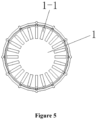
Figure 5 is a bottom view ofFigure 4 . -
1 top lid, 1-1 groove, 2 cap body, 2-1 first casing, 2-2 second casing, 2-3 serrated protrusion, 2-4 contact point, 2-5 connecting structure. - The present application will be further described in conjunction with the accompany drawings and specific embodiments, so that purposes, technical solutions and advantages of the present application can be more obvious and understandable. It should be understood that the specific embodiments described herein are only intended for interpreting the present application rather than limiting the present application. All other embodiments obtained by those skilled in the art based on the embodiments in the present application without any creative work belong to the scope of protection of the present application.
- A self-destruct-upon-opening cap applicable to a feeder used for a gastrointestinal tract is provided according to the present application, as shown in
figures 1 to 5 . The cap includes atop lid 1 and acap body 2, thetop lid 1 is arranged on thecap body 2 and is fixedly connected to thecap body 2, and generally, thetop lid 1 and thecap body 2 may be made into an integral structure through ultrasonic thermal bonding. A connecting structure for connecting with the feeder used for the gastrointestinal tract is arranged at one end of thecap body 2 which is not connected to thetop lid 1, and the connecting structure may employ a conventional connecting structure. Thecap body 2 includes a first casing 2-1 and a second casing 2-2, the first casing 2-1 is fixedly connected to thetop lid 1, and the connecting structure 2-5 is located in the second casing 2-2. One side of the second casing 2-2 which is not provided with the connecting structure 2-5 extends into the first casing 2-1, and a top face of the second casing 2-2 is provided with multiple serrated protrusions 2-3 in a circumferential direction. The side of the second casing 2-2 which is not provided with the connecting structure 2-5 is fixedly connected to the first casing 2-1 through 2 to 4 ribs or contact points 2-4, the ribs may be made into an integral structure with the first casing 2-1 and the second casing 2-2 through ultrasonic heat thermal bonding, and the ribs may also be integrally formed with the first casing 2-1 and the second casing 2-2. An inner side face of thetop lid 1 is provided with multiple grooves 1-1 matching with the serrated protrusions 2-3, and the serrated protrusions 2-3 are located inside the grooves 1-1. - The above connecting structure may employ the conventional connecting structure, such as the screw structure specified by standard ISO 80369-3.
- When the cap is used, in a process of screwing the cap onto a head portion of the feeder, since the grooves of the top lid of the cap and the serrated protrusions on the top face of the second casing are mutually engaged and locked, an acting force during the screwing process is applied mainly to the second casing and the top lid, rather than the ribs (or the contact points) connecting the first casing and the second casing. Therefore, the first casing will and the second casing will neither move with respect to each other nor be separated from each other due to the rotation, and thus the cap sealed on the head portion of the feeder remains intact during and after the screwing process. When the cap is unscrewed from the head portion of the feeder, since both the grooves of the top lid of the cap and the serrated protrusions on the top face of the second casing are arranged in a forward-slanted tooth shape in a direction that the cap is unscrewed, the serrated protrusions are separated from the grooves during the process that the cap is unscrewed from the head portion of the feeder, and a sliding thrust is generated on slanted surfaces where the serrated protrusions and the grooves are in contact with each other. The sliding thrust and a rotating force act on the ribs (or the contact points) between the first casing and the second casing at the same time, causing the fragile ribs or contact points to be broken, and thus the first casing together with the top lid are separated from the second casing, and only the second casing is left for sealing the head portion of the feeder. In this case, a clinician authorized for feeding in the ward can easily identify whether the feeder has been tampered or not, and if the first casing of the cap is broken or missing, the clinician will immediately find that the feeder has been tampered and will not use it, thus avoiding the risks of cross use or reuse, as well as the risks that pharmaceuticals may be transferred, replaced or abused, and thereby effectively ensuring the safety and reliability of the clinical use of sterile pharmaceutical preparations and feeders. In addition, when the authorized clinician in the ward gets the feeder with the intact sealing cap, under the controlled management of the authorized clinician, the cap having only the second casing left after the cap is opened can still ensure the sealing of the head portion of the feeder. In this way, the self-destruct-upon-opening cap is not only beneficial for identifying whether the feeder is tampered, but also facilitates the authorized clinician to carry out clinical operations.
- A difference between
Embodiment 2 andEmbodiment 1 is as follows. InEmbodiment 2, serrated protrusions are provided on the inner side face of the top lid in the circumferential direction, and grooves matching with the serrated protrusions are provided at the top face of the second casing. The principle ofEmbodiment 2 is the same as or similar to that ofEmbodiment 1, which will not be described herein. - The embodiments described hereinbefore are only the embodiments of the present application, and the description is specific and detailed, which cannot be understood as the limitation of the scope of the present application. It should be noted that, many modifications and improvements can be made by those skilled in the art without departing from the concept of the present application, and all these modifications and improvements belong to the protection scope of the present application.
Claims (5)
- A self-destruct-upon-opening cap for a small-diameter connector applied to a gastrointestinal tract, comprising a top lid (1) and a cap body (2), whereinthe top lid (1) is arranged on the cap body (2) and is fixedly connected to the cap body (2), a connecting structure (2-5) configured for matching and connecting with the small-diameter connector applied to the gastrointestinal tract is arranged at one end of the cap body (2) which is not connected to the top lid (1);the cap body (2) comprises a first casing (2-1) and a second casing (2-2), and the first casing (2-1) is fixedly connected to the top lid (1);the connecting structure (2-5) is located in the second casing (2-2);one side of the second casing (2-2) which is not provided with the connecting structure (2-5) extends, toward the top lid (1), into the first casing (2-1), and a top face of the second casing (2-2) is provided with serrated protrusions (2-3) in a circumferential direction;the side of the second casing (2-2) which is not provided with the connecting structure (2-5) is fixedly connected to the first casing (2-1) through ribs or contact points (2-4) in a breakable manner; andan inner side face of the top lid (1) is provided with grooves (1-1) matching with the serrated protrusions (2-3), the serrated protrusions (2-3) are located inside the grooves (1-1), and the grooves (1-1) and the serrated protrusions (2-3) are arranged in a forward-slanted tooth shape in a direction that the self-destruct-upon-opening cap is unscrewed.
- The self-destruct-upon-opening cap for the small-diameter connector applied to the gastrointestinal tract according to claim 1, wherein the connecting structure (2-5) is a threaded structure.
- The self-destruct-upon-opening cap for the small-diameter connector applied to the gastrointestinal tract according to claim 2, wherein the threaded structure is configured to be connected to the small-diameter connector applied to the gastrointestinal tract.
- The self-destruct-upon-opening cap for the small-diameter connector applied to the gastrointestinal tract according to any one of claims 1 to 3, wherein each of the grooves (1-1) is a concave slope structure, the grooves (1-1) are arranged in a forward-slanted tooth shape in one direction of the circumferential direction, and in a backward-slanted tooth shape in another reversed direction of the circumferential direction.
- The self-destruct-upon-opening cap for the small-diameter connector applied to the gastrointestinal tract according to any one of claims 1 to 4, wherein positions of the serrated protrusions (2-3) and positions of the grooves (1-1) are allowed to be exchanged with each other.
Applications Claiming Priority (2)
| Application Number | Priority Date | Filing Date | Title |
|---|---|---|---|
| CN202010152116.2A CN111135453B (en) | 2020-03-06 | 2020-03-06 | Open-and-destroy cap for gastrointestinal tract application small-caliber connector |
| PCT/CN2020/092301 WO2021174686A1 (en) | 2020-03-06 | 2020-05-26 | Cap that is destroyed once opened for small-caliber connector for gastrointestinal application |
Publications (3)
| Publication Number | Publication Date |
|---|---|
| EP3903874A1 EP3903874A1 (en) | 2021-11-03 |
| EP3903874A4 EP3903874A4 (en) | 2022-03-23 |
| EP3903874B1 true EP3903874B1 (en) | 2025-05-14 |
Family
ID=70528352
Family Applications (1)
| Application Number | Title | Priority Date | Filing Date |
|---|---|---|---|
| EP20827959.6A Active EP3903874B1 (en) | 2020-03-06 | 2020-05-26 | Cap that is destroyed once opened for small-caliber connector for gastrointestinal application |
Country Status (5)
| Country | Link |
|---|---|
| US (1) | US11111058B1 (en) |
| EP (1) | EP3903874B1 (en) |
| CN (1) | CN111135453B (en) |
| CA (1) | CA3101449C (en) |
| WO (1) | WO2021174686A1 (en) |
Families Citing this family (1)
| Publication number | Priority date | Publication date | Assignee | Title |
|---|---|---|---|---|
| CN111135453B (en) * | 2020-03-06 | 2024-08-27 | 安徽天康医疗科技股份有限公司 | Open-and-destroy cap for gastrointestinal tract application small-caliber connector |
Family Cites Families (29)
| Publication number | Priority date | Publication date | Assignee | Title |
|---|---|---|---|---|
| US2124874A (en) * | 1934-05-04 | 1938-07-26 | Colt S Mfg Co | Container closure means |
| US2054012A (en) * | 1934-05-22 | 1936-09-08 | Colt S Mfg Co | Container closure means |
| US4043334A (en) * | 1976-06-29 | 1977-08-23 | American Hospital Supply Corporation | Self righting syringe protector |
| AU518607B2 (en) * | 1978-08-28 | 1981-10-08 | Brickwood Holdings Pty. Ltd. | Tamper proof container and closure |
| US4726483A (en) * | 1987-05-18 | 1988-02-23 | Captive Plastics, Inc. | Tamper-evident closure employing inner cap and outer sleeve and container utilized therewith |
| US4941580A (en) * | 1989-05-26 | 1990-07-17 | Sunbeam Plastics Corporation | Dispensing closure |
| US5314084A (en) * | 1992-08-21 | 1994-05-24 | The West Company, Incorporated | Two piece all plastic seal |
| US7316669B2 (en) * | 2002-08-22 | 2008-01-08 | Baxa Corporation | Protective cap for medical male luer fittings |
| US20040225258A1 (en) * | 2002-03-30 | 2004-11-11 | Ernest Balestracci | Tamper evident overcap for a container |
| US7632244B2 (en) * | 2006-08-10 | 2009-12-15 | Comar, Inc. | Tamper evident tip cap assembly |
| EP2646095B1 (en) * | 2010-11-30 | 2016-10-19 | Teva Pharmaceutical Industries Ltd. | Inhalers with housing caps for inhalers |
| US9629977B2 (en) * | 2012-11-09 | 2017-04-25 | Carefusion 303, Inc. | Capping device for a medical access connector |
| EP2859911A1 (en) * | 2013-10-11 | 2015-04-15 | qSTAR Medical SAS | Vascular access port devices with incorporated sensors |
| USD759486S1 (en) * | 2014-09-08 | 2016-06-21 | Neomed, Inc. | Syringe tip cap |
| US10688251B2 (en) * | 2014-09-08 | 2020-06-23 | Neomed, Inc. | Self-righting tip cap |
| US10773067B2 (en) * | 2014-09-08 | 2020-09-15 | Neomed, Inc. | Enteral connectors having coupling features |
| USD797929S1 (en) * | 2015-03-25 | 2017-09-19 | Neomed, Inc. | Tip cap for fluid delivery device |
| IL239366B (en) * | 2015-06-11 | 2018-07-31 | Kriheli Marino | Components of a fluid transfer device |
| US10039913B2 (en) * | 2015-07-30 | 2018-08-07 | Carefusion 303, Inc. | Tamper-resistant cap |
| US9937301B2 (en) * | 2016-06-10 | 2018-04-10 | Baxter Corporation Englewood | Tamper evident syringe tip cap |
| DE102016116098A1 (en) * | 2016-08-30 | 2018-03-01 | B. Braun Avitum Ag | Cap for a cartridge-shaped container |
| CN206924201U (en) * | 2016-12-20 | 2018-01-26 | 江苏苏云医疗器材有限公司 | A kind of enteral connector protects block |
| JPWO2018164250A1 (en) * | 2017-03-10 | 2020-01-09 | テルモ株式会社 | Syringe assembly and prefilled syringe |
| CN206719896U (en) * | 2017-04-18 | 2017-12-08 | 苏州苏博包装有限公司 | Multi-function container cover and multifunction container |
| JP7104064B2 (en) * | 2017-04-21 | 2022-07-20 | ベクトン・ディキンソン・アンド・カンパニー | Connector cap |
| US11103654B2 (en) * | 2018-02-08 | 2021-08-31 | Nordson Corporation | Tamper-evident closure |
| GB2576009A (en) * | 2018-08-01 | 2020-02-05 | Obrist Closures Switzerland | A tamper-evident closure |
| CN111135453B (en) * | 2020-03-06 | 2024-08-27 | 安徽天康医疗科技股份有限公司 | Open-and-destroy cap for gastrointestinal tract application small-caliber connector |
| CN212547954U (en) * | 2020-03-06 | 2021-02-19 | 安徽天康医疗科技股份有限公司 | A quick-open cap for a small-bore connector for gastrointestinal application |
-
2020
- 2020-03-06 CN CN202010152116.2A patent/CN111135453B/en active Active
- 2020-05-26 CA CA3101449A patent/CA3101449C/en active Active
- 2020-05-26 WO PCT/CN2020/092301 patent/WO2021174686A1/en not_active Ceased
- 2020-05-26 EP EP20827959.6A patent/EP3903874B1/en active Active
- 2020-06-08 US US16/895,646 patent/US11111058B1/en active Active
Also Published As
| Publication number | Publication date |
|---|---|
| EP3903874A4 (en) | 2022-03-23 |
| CA3101449C (en) | 2023-03-21 |
| BR112022012168A2 (en) | 2022-10-18 |
| WO2021174686A1 (en) | 2021-09-10 |
| EP3903874A1 (en) | 2021-11-03 |
| US11111058B1 (en) | 2021-09-07 |
| US20210275401A1 (en) | 2021-09-09 |
| CN111135453B (en) | 2024-08-27 |
| CN111135453A (en) | 2020-05-12 |
| CA3101449A1 (en) | 2021-09-06 |
Similar Documents
| Publication | Publication Date | Title |
|---|---|---|
| EP2376147B1 (en) | Improved drug container | |
| JP4300285B2 (en) | Infusion device for single doses of liquids, especially pharmaceutical liquids | |
| US20200094036A1 (en) | Mechanical Friction Enhancement for Threaded Connection Incorporating Crushable Ribs | |
| CN202654494U (en) | Safe pen-type needle component | |
| EP0832658B1 (en) | A protective sealing barrier for a syringe | |
| KR102789526B1 (en) | Tip caps for medical syringe devices | |
| EP2000164B1 (en) | Self-destroying disposable syringe | |
| EP1044698A1 (en) | Pre-filled tamper evident syringe assembly | |
| US5489272A (en) | Injection syringe | |
| AU2788499A (en) | Vial transferset and method | |
| EP1082153A2 (en) | Safety syringe with retractable needle and universal luer coupling | |
| EP0904763B1 (en) | A locking ring connector assembly for a vial | |
| CA3101449C (en) | Self-destruct-upon-opening cap applicable to small-diameter connector used for gastrointestinal tract | |
| JP2919966B2 (en) | Unit dose container | |
| US10814075B2 (en) | Plug for placing on a connection element of a medical syringe | |
| CN212547954U (en) | A quick-open cap for a small-bore connector for gastrointestinal application | |
| US20190083716A1 (en) | Injection moulded needle assembly | |
| JP4646658B2 (en) | Prefilled syringe | |
| BR112022012168B1 (en) | PLUG THAT IS DESTROYED ONCE OPENED FOR SMALL GAUGE CONNECTOR FOR GASTROINTESTINAL APPLICATION | |
| US20250281695A1 (en) | Castellated Syringe Product Label | |
| CN214633018U (en) | Direct-insertion type feeding device tamper-proof cap | |
| CN216710301U (en) | Medicine feeder | |
| CN109125857B (en) | Pen needle multi-carrier injection system | |
| WO2000007648A9 (en) | Prefilled syringe with means for preventing plunger removal | |
| HK1032208A (en) | Pre-filled tamper evident syringe assembly |
Legal Events
| Date | Code | Title | Description |
|---|---|---|---|
| STAA | Information on the status of an ep patent application or granted ep patent |
Free format text: STATUS: UNKNOWN |
|
| STAA | Information on the status of an ep patent application or granted ep patent |
Free format text: STATUS: THE INTERNATIONAL PUBLICATION HAS BEEN MADE |
|
| PUAI | Public reference made under article 153(3) epc to a published international application that has entered the european phase |
Free format text: ORIGINAL CODE: 0009012 |
|
| STAA | Information on the status of an ep patent application or granted ep patent |
Free format text: STATUS: REQUEST FOR EXAMINATION WAS MADE |
|
| 17P | Request for examination filed |
Effective date: 20201228 |
|
| AK | Designated contracting states |
Kind code of ref document: A1 Designated state(s): AL AT BE BG CH CY CZ DE DK EE ES FI FR GB GR HR HU IE IS IT LI LT LU LV MC MK MT NL NO PL PT RO RS SE SI SK SM TR |
|
| A4 | Supplementary search report drawn up and despatched |
Effective date: 20220217 |
|
| RIC1 | Information provided on ipc code assigned before grant |
Ipc: B65D 55/02 20060101ALI20220215BHEP Ipc: A61J 1/18 20060101ALI20220215BHEP Ipc: A61J 1/14 20060101ALI20220215BHEP Ipc: A61M 5/50 20060101ALI20220215BHEP Ipc: B65D 47/02 20060101ALI20220215BHEP Ipc: A61J 15/00 20060101ALI20220215BHEP Ipc: A61M 39/20 20060101AFI20220215BHEP |
|
| DAV | Request for validation of the european patent (deleted) | ||
| DAX | Request for extension of the european patent (deleted) | ||
| GRAP | Despatch of communication of intention to grant a patent |
Free format text: ORIGINAL CODE: EPIDOSNIGR1 |
|
| STAA | Information on the status of an ep patent application or granted ep patent |
Free format text: STATUS: GRANT OF PATENT IS INTENDED |
|
| INTG | Intention to grant announced |
Effective date: 20241211 |
|
| GRAS | Grant fee paid |
Free format text: ORIGINAL CODE: EPIDOSNIGR3 |
|
| GRAA | (expected) grant |
Free format text: ORIGINAL CODE: 0009210 |
|
| STAA | Information on the status of an ep patent application or granted ep patent |
Free format text: STATUS: THE PATENT HAS BEEN GRANTED |
|
| AK | Designated contracting states |
Kind code of ref document: B1 Designated state(s): AL AT BE BG CH CY CZ DE DK EE ES FI FR GB GR HR HU IE IS IT LI LT LU LV MC MK MT NL NO PL PT RO RS SE SI SK SM TR |
|
| REG | Reference to a national code |
Ref country code: GB Ref legal event code: FG4D |
|
| REG | Reference to a national code |
Ref country code: CH Ref legal event code: EP |
|
| REG | Reference to a national code |
Ref country code: IE Ref legal event code: FG4D |
|
| REG | Reference to a national code |
Ref country code: DE Ref legal event code: R096 Ref document number: 602020051357 Country of ref document: DE |
|
| PGFP | Annual fee paid to national office [announced via postgrant information from national office to epo] |
Ref country code: DE Payment date: 20250617 Year of fee payment: 6 |
|
| PGFP | Annual fee paid to national office [announced via postgrant information from national office to epo] |
Ref country code: GB Payment date: 20250625 Year of fee payment: 6 |
|
| PGFP | Annual fee paid to national office [announced via postgrant information from national office to epo] |
Ref country code: FR Payment date: 20250530 Year of fee payment: 6 |
|
| P01 | Opt-out of the competence of the unified patent court (upc) registered |
Free format text: CASE NUMBER: UPC_APP_2035_3903874/2025 Effective date: 20250731 |
|
| REG | Reference to a national code |
Ref country code: NL Ref legal event code: MP Effective date: 20250514 |
|
| PG25 | Lapsed in a contracting state [announced via postgrant information from national office to epo] |
Ref country code: PT Free format text: LAPSE BECAUSE OF FAILURE TO SUBMIT A TRANSLATION OF THE DESCRIPTION OR TO PAY THE FEE WITHIN THE PRESCRIBED TIME-LIMIT Effective date: 20250915 Ref country code: ES Free format text: LAPSE BECAUSE OF FAILURE TO SUBMIT A TRANSLATION OF THE DESCRIPTION OR TO PAY THE FEE WITHIN THE PRESCRIBED TIME-LIMIT Effective date: 20250514 Ref country code: FI Free format text: LAPSE BECAUSE OF FAILURE TO SUBMIT A TRANSLATION OF THE DESCRIPTION OR TO PAY THE FEE WITHIN THE PRESCRIBED TIME-LIMIT Effective date: 20250514 |
|
| REG | Reference to a national code |
Ref country code: LT Ref legal event code: MG9D |
|
| PG25 | Lapsed in a contracting state [announced via postgrant information from national office to epo] |
Ref country code: GR Free format text: LAPSE BECAUSE OF FAILURE TO SUBMIT A TRANSLATION OF THE DESCRIPTION OR TO PAY THE FEE WITHIN THE PRESCRIBED TIME-LIMIT Effective date: 20250815 Ref country code: NO Free format text: LAPSE BECAUSE OF FAILURE TO SUBMIT A TRANSLATION OF THE DESCRIPTION OR TO PAY THE FEE WITHIN THE PRESCRIBED TIME-LIMIT Effective date: 20250814 |
|
| PG25 | Lapsed in a contracting state [announced via postgrant information from national office to epo] |
Ref country code: NL Free format text: LAPSE BECAUSE OF FAILURE TO SUBMIT A TRANSLATION OF THE DESCRIPTION OR TO PAY THE FEE WITHIN THE PRESCRIBED TIME-LIMIT Effective date: 20250514 Ref country code: PL Free format text: LAPSE BECAUSE OF FAILURE TO SUBMIT A TRANSLATION OF THE DESCRIPTION OR TO PAY THE FEE WITHIN THE PRESCRIBED TIME-LIMIT Effective date: 20250514 |
|
| REG | Reference to a national code |
Ref country code: AT Ref legal event code: MK05 Ref document number: 1794325 Country of ref document: AT Kind code of ref document: T Effective date: 20250514 |
|
| PG25 | Lapsed in a contracting state [announced via postgrant information from national office to epo] |
Ref country code: BG Free format text: LAPSE BECAUSE OF FAILURE TO SUBMIT A TRANSLATION OF THE DESCRIPTION OR TO PAY THE FEE WITHIN THE PRESCRIBED TIME-LIMIT Effective date: 20250514 |
|
| PG25 | Lapsed in a contracting state [announced via postgrant information from national office to epo] |
Ref country code: HR Free format text: LAPSE BECAUSE OF FAILURE TO SUBMIT A TRANSLATION OF THE DESCRIPTION OR TO PAY THE FEE WITHIN THE PRESCRIBED TIME-LIMIT Effective date: 20250514 |
|
| PG25 | Lapsed in a contracting state [announced via postgrant information from national office to epo] |
Ref country code: AT Free format text: LAPSE BECAUSE OF FAILURE TO SUBMIT A TRANSLATION OF THE DESCRIPTION OR TO PAY THE FEE WITHIN THE PRESCRIBED TIME-LIMIT Effective date: 20250514 |
|
| PG25 | Lapsed in a contracting state [announced via postgrant information from national office to epo] |
Ref country code: RS Free format text: LAPSE BECAUSE OF FAILURE TO SUBMIT A TRANSLATION OF THE DESCRIPTION OR TO PAY THE FEE WITHIN THE PRESCRIBED TIME-LIMIT Effective date: 20250814 |
|
| PG25 | Lapsed in a contracting state [announced via postgrant information from national office to epo] |
Ref country code: IS Free format text: LAPSE BECAUSE OF FAILURE TO SUBMIT A TRANSLATION OF THE DESCRIPTION OR TO PAY THE FEE WITHIN THE PRESCRIBED TIME-LIMIT Effective date: 20250914 |
|
| PG25 | Lapsed in a contracting state [announced via postgrant information from national office to epo] |
Ref country code: LV Free format text: LAPSE BECAUSE OF FAILURE TO SUBMIT A TRANSLATION OF THE DESCRIPTION OR TO PAY THE FEE WITHIN THE PRESCRIBED TIME-LIMIT Effective date: 20250514 |
|
| REG | Reference to a national code |
Ref country code: CH Ref legal event code: H13 Free format text: ST27 STATUS EVENT CODE: U-0-0-H10-H13 (AS PROVIDED BY THE NATIONAL OFFICE) Effective date: 20251223 |
|
| PG25 | Lapsed in a contracting state [announced via postgrant information from national office to epo] |
Ref country code: SM Free format text: LAPSE BECAUSE OF FAILURE TO SUBMIT A TRANSLATION OF THE DESCRIPTION OR TO PAY THE FEE WITHIN THE PRESCRIBED TIME-LIMIT Effective date: 20250514 Ref country code: DK Free format text: LAPSE BECAUSE OF FAILURE TO SUBMIT A TRANSLATION OF THE DESCRIPTION OR TO PAY THE FEE WITHIN THE PRESCRIBED TIME-LIMIT Effective date: 20250514 |
|
| PG25 | Lapsed in a contracting state [announced via postgrant information from national office to epo] |
Ref country code: LU Free format text: LAPSE BECAUSE OF NON-PAYMENT OF DUE FEES Effective date: 20250526 |
|
| PG25 | Lapsed in a contracting state [announced via postgrant information from national office to epo] |
Ref country code: CH Free format text: LAPSE BECAUSE OF NON-PAYMENT OF DUE FEES Effective date: 20250531 |
|
| PG25 | Lapsed in a contracting state [announced via postgrant information from national office to epo] |
Ref country code: CZ Free format text: LAPSE BECAUSE OF FAILURE TO SUBMIT A TRANSLATION OF THE DESCRIPTION OR TO PAY THE FEE WITHIN THE PRESCRIBED TIME-LIMIT Effective date: 20250514 |
|
| PG25 | Lapsed in a contracting state [announced via postgrant information from national office to epo] |
Ref country code: EE Free format text: LAPSE BECAUSE OF FAILURE TO SUBMIT A TRANSLATION OF THE DESCRIPTION OR TO PAY THE FEE WITHIN THE PRESCRIBED TIME-LIMIT Effective date: 20250514 |
|
| PG25 | Lapsed in a contracting state [announced via postgrant information from national office to epo] |
Ref country code: SK Free format text: LAPSE BECAUSE OF FAILURE TO SUBMIT A TRANSLATION OF THE DESCRIPTION OR TO PAY THE FEE WITHIN THE PRESCRIBED TIME-LIMIT Effective date: 20250514 Ref country code: RO Free format text: LAPSE BECAUSE OF FAILURE TO SUBMIT A TRANSLATION OF THE DESCRIPTION OR TO PAY THE FEE WITHIN THE PRESCRIBED TIME-LIMIT Effective date: 20250514 |
|
| PG25 | Lapsed in a contracting state [announced via postgrant information from national office to epo] |
Ref country code: IT Free format text: LAPSE BECAUSE OF FAILURE TO SUBMIT A TRANSLATION OF THE DESCRIPTION OR TO PAY THE FEE WITHIN THE PRESCRIBED TIME-LIMIT Effective date: 20250514 |
|
| REG | Reference to a national code |
Ref country code: BE Ref legal event code: MM Effective date: 20250531 |
|
| REG | Reference to a national code |
Ref country code: DE Ref legal event code: R097 Ref document number: 602020051357 Country of ref document: DE |
|
| PG25 | Lapsed in a contracting state [announced via postgrant information from national office to epo] |
Ref country code: MC Free format text: LAPSE BECAUSE OF FAILURE TO SUBMIT A TRANSLATION OF THE DESCRIPTION OR TO PAY THE FEE WITHIN THE PRESCRIBED TIME-LIMIT Effective date: 20250514 |
|
| PLBE | No opposition filed within time limit |
Free format text: ORIGINAL CODE: 0009261 |
|
| STAA | Information on the status of an ep patent application or granted ep patent |
Free format text: STATUS: NO OPPOSITION FILED WITHIN TIME LIMIT |
|
| REG | Reference to a national code |
Ref country code: CH Ref legal event code: L10 Free format text: ST27 STATUS EVENT CODE: U-0-0-L10-L00 (AS PROVIDED BY THE NATIONAL OFFICE) Effective date: 20260325 |
|
| PG25 | Lapsed in a contracting state [announced via postgrant information from national office to epo] |
Ref country code: IE Free format text: LAPSE BECAUSE OF NON-PAYMENT OF DUE FEES Effective date: 20250526 |
|
| PG25 | Lapsed in a contracting state [announced via postgrant information from national office to epo] |
Ref country code: BE Free format text: LAPSE BECAUSE OF NON-PAYMENT OF DUE FEES Effective date: 20250531 |
|
| 26N | No opposition filed |
Effective date: 20260217 |