EP3903701B1 - Endovascular device with a tissue piercing distal probe - Google Patents
Endovascular device with a tissue piercing distal probe Download PDFInfo
- Publication number
- EP3903701B1 EP3903701B1 EP21175649.9A EP21175649A EP3903701B1 EP 3903701 B1 EP3903701 B1 EP 3903701B1 EP 21175649 A EP21175649 A EP 21175649A EP 3903701 B1 EP3903701 B1 EP 3903701B1
- Authority
- EP
- European Patent Office
- Prior art keywords
- entry device
- probe
- distal
- aperture
- orienting
- Prior art date
- Legal status (The legal status is an assumption and is not a legal conclusion. Google has not performed a legal analysis and makes no representation as to the accuracy of the status listed.)
- Active
Links
- 239000000523 sample Substances 0.000 title claims description 45
- 239000000463 material Substances 0.000 claims description 7
- 210000001367 artery Anatomy 0.000 description 39
- 238000000034 method Methods 0.000 description 21
- 210000002808 connective tissue Anatomy 0.000 description 19
- 210000004204 blood vessel Anatomy 0.000 description 14
- 230000017531 blood circulation Effects 0.000 description 6
- 230000001684 chronic effect Effects 0.000 description 6
- 210000004351 coronary vessel Anatomy 0.000 description 6
- 238000004891 communication Methods 0.000 description 5
- 239000012530 fluid Substances 0.000 description 5
- 210000001519 tissue Anatomy 0.000 description 5
- 230000000903 blocking effect Effects 0.000 description 4
- 210000005224 forefinger Anatomy 0.000 description 4
- 210000003813 thumb Anatomy 0.000 description 4
- 238000002399 angioplasty Methods 0.000 description 3
- 210000004247 hand Anatomy 0.000 description 3
- 238000004519 manufacturing process Methods 0.000 description 3
- 230000003068 static effect Effects 0.000 description 3
- BQCADISMDOOEFD-UHFFFAOYSA-N Silver Chemical compound [Ag] BQCADISMDOOEFD-UHFFFAOYSA-N 0.000 description 2
- 230000008901 benefit Effects 0.000 description 2
- HVYWMOMLDIMFJA-DPAQBDIFSA-N cholesterol Chemical compound C1C=C2C[C@@H](O)CC[C@]2(C)[C@@H]2[C@@H]1[C@@H]1CC[C@H]([C@H](C)CCCC(C)C)[C@@]1(C)CC2 HVYWMOMLDIMFJA-DPAQBDIFSA-N 0.000 description 2
- 238000002224 dissection Methods 0.000 description 2
- 239000003550 marker Substances 0.000 description 2
- 230000008569 process Effects 0.000 description 2
- 229910052709 silver Inorganic materials 0.000 description 2
- 239000004332 silver Substances 0.000 description 2
- 206010002383 Angina Pectoris Diseases 0.000 description 1
- 201000001320 Atherosclerosis Diseases 0.000 description 1
- 239000008280 blood Substances 0.000 description 1
- 210000004369 blood Anatomy 0.000 description 1
- 238000005219 brazing Methods 0.000 description 1
- 210000000748 cardiovascular system Anatomy 0.000 description 1
- 238000005266 casting Methods 0.000 description 1
- 235000012000 cholesterol Nutrition 0.000 description 1
- 230000001419 dependent effect Effects 0.000 description 1
- 208000037765 diseases and disorders Diseases 0.000 description 1
- 210000003414 extremity Anatomy 0.000 description 1
- 210000001105 femoral artery Anatomy 0.000 description 1
- 230000036541 health Effects 0.000 description 1
- 210000005003 heart tissue Anatomy 0.000 description 1
- 208000014674 injury Diseases 0.000 description 1
- 208000028867 ischemia Diseases 0.000 description 1
- 230000003902 lesion Effects 0.000 description 1
- 238000011542 limb amputation Methods 0.000 description 1
- 238000003754 machining Methods 0.000 description 1
- 238000000465 moulding Methods 0.000 description 1
- 210000004165 myocardium Anatomy 0.000 description 1
- 230000037361 pathway Effects 0.000 description 1
- 210000003137 popliteal artery Anatomy 0.000 description 1
- 238000009877 rendering Methods 0.000 description 1
- 238000005096 rolling process Methods 0.000 description 1
- 229910000679 solder Inorganic materials 0.000 description 1
- 238000005476 soldering Methods 0.000 description 1
- 238000001356 surgical procedure Methods 0.000 description 1
- 208000024891 symptom Diseases 0.000 description 1
- 230000007704 transition Effects 0.000 description 1
- 230000008733 trauma Effects 0.000 description 1
- 230000002792 vascular Effects 0.000 description 1
- 210000005166 vasculature Anatomy 0.000 description 1
- 238000003466 welding Methods 0.000 description 1
Images


Classifications
-
- A—HUMAN NECESSITIES
- A61—MEDICAL OR VETERINARY SCIENCE; HYGIENE
- A61B—DIAGNOSIS; SURGERY; IDENTIFICATION
- A61B17/00—Surgical instruments, devices or methods, e.g. tourniquets
- A61B17/32—Surgical cutting instruments
- A61B17/3205—Excision instruments
- A61B17/3207—Atherectomy devices working by cutting or abrading; Similar devices specially adapted for non-vascular obstructions
-
- A—HUMAN NECESSITIES
- A61—MEDICAL OR VETERINARY SCIENCE; HYGIENE
- A61B—DIAGNOSIS; SURGERY; IDENTIFICATION
- A61B17/00—Surgical instruments, devices or methods, e.g. tourniquets
- A61B17/11—Surgical instruments, devices or methods, e.g. tourniquets for performing anastomosis; Buttons for anastomosis
-
- A—HUMAN NECESSITIES
- A61—MEDICAL OR VETERINARY SCIENCE; HYGIENE
- A61B—DIAGNOSIS; SURGERY; IDENTIFICATION
- A61B17/00—Surgical instruments, devices or methods, e.g. tourniquets
- A61B17/34—Trocars; Puncturing needles
- A61B17/3478—Endoscopic needles, e.g. for infusion
-
- A—HUMAN NECESSITIES
- A61—MEDICAL OR VETERINARY SCIENCE; HYGIENE
- A61M—DEVICES FOR INTRODUCING MEDIA INTO, OR ONTO, THE BODY; DEVICES FOR TRANSDUCING BODY MEDIA OR FOR TAKING MEDIA FROM THE BODY; DEVICES FOR PRODUCING OR ENDING SLEEP OR STUPOR
- A61M25/00—Catheters; Hollow probes
- A61M25/01—Introducing, guiding, advancing, emplacing or holding catheters
- A61M25/09—Guide wires
-
- A—HUMAN NECESSITIES
- A61—MEDICAL OR VETERINARY SCIENCE; HYGIENE
- A61B—DIAGNOSIS; SURGERY; IDENTIFICATION
- A61B17/00—Surgical instruments, devices or methods, e.g. tourniquets
- A61B17/32—Surgical cutting instruments
- A61B17/3205—Excision instruments
- A61B17/3207—Atherectomy devices working by cutting or abrading; Similar devices specially adapted for non-vascular obstructions
- A61B17/320758—Atherectomy devices working by cutting or abrading; Similar devices specially adapted for non-vascular obstructions with a rotating cutting instrument, e.g. motor driven
-
- A—HUMAN NECESSITIES
- A61—MEDICAL OR VETERINARY SCIENCE; HYGIENE
- A61B—DIAGNOSIS; SURGERY; IDENTIFICATION
- A61B17/00—Surgical instruments, devices or methods, e.g. tourniquets
- A61B17/00234—Surgical instruments, devices or methods, e.g. tourniquets for minimally invasive surgery
- A61B2017/00238—Type of minimally invasive operation
- A61B2017/00243—Type of minimally invasive operation cardiac
- A61B2017/00247—Making holes in the wall of the heart, e.g. laser Myocardial revascularization
- A61B2017/00252—Making holes in the wall of the heart, e.g. laser Myocardial revascularization for by-pass connections, i.e. connections from heart chamber to blood vessel or from blood vessel to blood vessel
-
- A—HUMAN NECESSITIES
- A61—MEDICAL OR VETERINARY SCIENCE; HYGIENE
- A61B—DIAGNOSIS; SURGERY; IDENTIFICATION
- A61B17/00—Surgical instruments, devices or methods, e.g. tourniquets
- A61B17/00234—Surgical instruments, devices or methods, e.g. tourniquets for minimally invasive surgery
- A61B2017/00292—Surgical instruments, devices or methods, e.g. tourniquets for minimally invasive surgery mounted on or guided by flexible, e.g. catheter-like, means
- A61B2017/00336—Surgical instruments, devices or methods, e.g. tourniquets for minimally invasive surgery mounted on or guided by flexible, e.g. catheter-like, means with a protective sleeve, e.g. retractable or slidable
-
- A—HUMAN NECESSITIES
- A61—MEDICAL OR VETERINARY SCIENCE; HYGIENE
- A61B—DIAGNOSIS; SURGERY; IDENTIFICATION
- A61B17/00—Surgical instruments, devices or methods, e.g. tourniquets
- A61B2017/0042—Surgical instruments, devices or methods, e.g. tourniquets with special provisions for gripping
- A61B2017/00438—Surgical instruments, devices or methods, e.g. tourniquets with special provisions for gripping connectable to a finger
-
- A—HUMAN NECESSITIES
- A61—MEDICAL OR VETERINARY SCIENCE; HYGIENE
- A61B—DIAGNOSIS; SURGERY; IDENTIFICATION
- A61B17/00—Surgical instruments, devices or methods, e.g. tourniquets
- A61B2017/00743—Type of operation; Specification of treatment sites
- A61B2017/00778—Operations on blood vessels
-
- A—HUMAN NECESSITIES
- A61—MEDICAL OR VETERINARY SCIENCE; HYGIENE
- A61B—DIAGNOSIS; SURGERY; IDENTIFICATION
- A61B17/00—Surgical instruments, devices or methods, e.g. tourniquets
- A61B17/11—Surgical instruments, devices or methods, e.g. tourniquets for performing anastomosis; Buttons for anastomosis
- A61B2017/1107—Surgical instruments, devices or methods, e.g. tourniquets for performing anastomosis; Buttons for anastomosis for blood vessels
-
- A—HUMAN NECESSITIES
- A61—MEDICAL OR VETERINARY SCIENCE; HYGIENE
- A61B—DIAGNOSIS; SURGERY; IDENTIFICATION
- A61B17/00—Surgical instruments, devices or methods, e.g. tourniquets
- A61B17/22—Implements for squeezing-off ulcers or the like on the inside of inner organs of the body; Implements for scraping-out cavities of body organs, e.g. bones; Calculus removers; Calculus smashing apparatus; Apparatus for removing obstructions in blood vessels, not otherwise provided for
- A61B2017/22038—Implements for squeezing-off ulcers or the like on the inside of inner organs of the body; Implements for scraping-out cavities of body organs, e.g. bones; Calculus removers; Calculus smashing apparatus; Apparatus for removing obstructions in blood vessels, not otherwise provided for with a guide wire
- A61B2017/22042—Details of the tip of the guide wire
- A61B2017/22044—Details of the tip of the guide wire with a pointed tip
-
- A—HUMAN NECESSITIES
- A61—MEDICAL OR VETERINARY SCIENCE; HYGIENE
- A61B—DIAGNOSIS; SURGERY; IDENTIFICATION
- A61B17/00—Surgical instruments, devices or methods, e.g. tourniquets
- A61B17/22—Implements for squeezing-off ulcers or the like on the inside of inner organs of the body; Implements for scraping-out cavities of body organs, e.g. bones; Calculus removers; Calculus smashing apparatus; Apparatus for removing obstructions in blood vessels, not otherwise provided for
- A61B2017/22038—Implements for squeezing-off ulcers or the like on the inside of inner organs of the body; Implements for scraping-out cavities of body organs, e.g. bones; Calculus removers; Calculus smashing apparatus; Apparatus for removing obstructions in blood vessels, not otherwise provided for with a guide wire
- A61B2017/22047—Means for immobilising the guide wire in the patient
- A61B2017/22048—Balloons
-
- A—HUMAN NECESSITIES
- A61—MEDICAL OR VETERINARY SCIENCE; HYGIENE
- A61B—DIAGNOSIS; SURGERY; IDENTIFICATION
- A61B17/00—Surgical instruments, devices or methods, e.g. tourniquets
- A61B17/22—Implements for squeezing-off ulcers or the like on the inside of inner organs of the body; Implements for scraping-out cavities of body organs, e.g. bones; Calculus removers; Calculus smashing apparatus; Apparatus for removing obstructions in blood vessels, not otherwise provided for
- A61B2017/22051—Implements for squeezing-off ulcers or the like on the inside of inner organs of the body; Implements for scraping-out cavities of body organs, e.g. bones; Calculus removers; Calculus smashing apparatus; Apparatus for removing obstructions in blood vessels, not otherwise provided for with an inflatable part, e.g. balloon, for positioning, blocking, or immobilisation
- A61B2017/22054—Implements for squeezing-off ulcers or the like on the inside of inner organs of the body; Implements for scraping-out cavities of body organs, e.g. bones; Calculus removers; Calculus smashing apparatus; Apparatus for removing obstructions in blood vessels, not otherwise provided for with an inflatable part, e.g. balloon, for positioning, blocking, or immobilisation with two balloons
-
- A—HUMAN NECESSITIES
- A61—MEDICAL OR VETERINARY SCIENCE; HYGIENE
- A61B—DIAGNOSIS; SURGERY; IDENTIFICATION
- A61B17/00—Surgical instruments, devices or methods, e.g. tourniquets
- A61B17/22—Implements for squeezing-off ulcers or the like on the inside of inner organs of the body; Implements for scraping-out cavities of body organs, e.g. bones; Calculus removers; Calculus smashing apparatus; Apparatus for removing obstructions in blood vessels, not otherwise provided for
- A61B2017/22094—Implements for squeezing-off ulcers or the like on the inside of inner organs of the body; Implements for scraping-out cavities of body organs, e.g. bones; Calculus removers; Calculus smashing apparatus; Apparatus for removing obstructions in blood vessels, not otherwise provided for for crossing total occlusions, i.e. piercing
- A61B2017/22095—Implements for squeezing-off ulcers or the like on the inside of inner organs of the body; Implements for scraping-out cavities of body organs, e.g. bones; Calculus removers; Calculus smashing apparatus; Apparatus for removing obstructions in blood vessels, not otherwise provided for for crossing total occlusions, i.e. piercing accessing a blood vessel true lumen from the sub-intimal space
-
- A—HUMAN NECESSITIES
- A61—MEDICAL OR VETERINARY SCIENCE; HYGIENE
- A61B—DIAGNOSIS; SURGERY; IDENTIFICATION
- A61B17/00—Surgical instruments, devices or methods, e.g. tourniquets
- A61B17/32—Surgical cutting instruments
- A61B2017/320044—Blunt dissectors
-
- A—HUMAN NECESSITIES
- A61—MEDICAL OR VETERINARY SCIENCE; HYGIENE
- A61B—DIAGNOSIS; SURGERY; IDENTIFICATION
- A61B17/00—Surgical instruments, devices or methods, e.g. tourniquets
- A61B17/34—Trocars; Puncturing needles
- A61B2017/348—Means for supporting the trocar against the body or retaining the trocar inside the body
- A61B2017/3482—Means for supporting the trocar against the body or retaining the trocar inside the body inside
- A61B2017/3484—Anchoring means, e.g. spreading-out umbrella-like structure
- A61B2017/3488—Fixation to inner organ or inner body tissue
-
- A—HUMAN NECESSITIES
- A61—MEDICAL OR VETERINARY SCIENCE; HYGIENE
- A61B—DIAGNOSIS; SURGERY; IDENTIFICATION
- A61B90/00—Instruments, implements or accessories specially adapted for surgery or diagnosis and not covered by any of the groups A61B1/00 - A61B50/00, e.g. for luxation treatment or for protecting wound edges
- A61B90/03—Automatic limiting or abutting means, e.g. for safety
- A61B2090/033—Abutting means, stops, e.g. abutting on tissue or skin
- A61B2090/036—Abutting means, stops, e.g. abutting on tissue or skin abutting on tissue or skin
-
- A—HUMAN NECESSITIES
- A61—MEDICAL OR VETERINARY SCIENCE; HYGIENE
- A61B—DIAGNOSIS; SURGERY; IDENTIFICATION
- A61B90/00—Instruments, implements or accessories specially adapted for surgery or diagnosis and not covered by any of the groups A61B1/00 - A61B50/00, e.g. for luxation treatment or for protecting wound edges
- A61B90/39—Markers, e.g. radio-opaque or breast lesions markers
-
- A—HUMAN NECESSITIES
- A61—MEDICAL OR VETERINARY SCIENCE; HYGIENE
- A61M—DEVICES FOR INTRODUCING MEDIA INTO, OR ONTO, THE BODY; DEVICES FOR TRANSDUCING BODY MEDIA OR FOR TAKING MEDIA FROM THE BODY; DEVICES FOR PRODUCING OR ENDING SLEEP OR STUPOR
- A61M25/00—Catheters; Hollow probes
- A61M25/0067—Catheters; Hollow probes characterised by the distal end, e.g. tips
- A61M25/0082—Catheter tip comprising a tool
- A61M2025/0096—Catheter tip comprising a tool being laterally outward extensions or tools, e.g. hooks or fibres
-
- A—HUMAN NECESSITIES
- A61—MEDICAL OR VETERINARY SCIENCE; HYGIENE
- A61M—DEVICES FOR INTRODUCING MEDIA INTO, OR ONTO, THE BODY; DEVICES FOR TRANSDUCING BODY MEDIA OR FOR TAKING MEDIA FROM THE BODY; DEVICES FOR PRODUCING OR ENDING SLEEP OR STUPOR
- A61M25/00—Catheters; Hollow probes
- A61M25/01—Introducing, guiding, advancing, emplacing or holding catheters
- A61M25/09—Guide wires
- A61M2025/09058—Basic structures of guide wires
- A61M2025/09083—Basic structures of guide wires having a coil around a core
-
- A—HUMAN NECESSITIES
- A61—MEDICAL OR VETERINARY SCIENCE; HYGIENE
- A61M—DEVICES FOR INTRODUCING MEDIA INTO, OR ONTO, THE BODY; DEVICES FOR TRANSDUCING BODY MEDIA OR FOR TAKING MEDIA FROM THE BODY; DEVICES FOR PRODUCING OR ENDING SLEEP OR STUPOR
- A61M25/00—Catheters; Hollow probes
- A61M25/01—Introducing, guiding, advancing, emplacing or holding catheters
- A61M25/09—Guide wires
- A61M2025/09175—Guide wires having specific characteristics at the distal tip
- A61M2025/09183—Guide wires having specific characteristics at the distal tip having tools at the distal tip
-
- A—HUMAN NECESSITIES
- A61—MEDICAL OR VETERINARY SCIENCE; HYGIENE
- A61M—DEVICES FOR INTRODUCING MEDIA INTO, OR ONTO, THE BODY; DEVICES FOR TRANSDUCING BODY MEDIA OR FOR TAKING MEDIA FROM THE BODY; DEVICES FOR PRODUCING OR ENDING SLEEP OR STUPOR
- A61M25/00—Catheters; Hollow probes
- A61M25/0067—Catheters; Hollow probes characterised by the distal end, e.g. tips
- A61M25/0068—Static characteristics of the catheter tip, e.g. shape, atraumatic tip, curved tip or tip structure
- A61M25/007—Side holes, e.g. their profiles or arrangements; Provisions to keep side holes unblocked
-
- A—HUMAN NECESSITIES
- A61—MEDICAL OR VETERINARY SCIENCE; HYGIENE
- A61M—DEVICES FOR INTRODUCING MEDIA INTO, OR ONTO, THE BODY; DEVICES FOR TRANSDUCING BODY MEDIA OR FOR TAKING MEDIA FROM THE BODY; DEVICES FOR PRODUCING OR ENDING SLEEP OR STUPOR
- A61M25/00—Catheters; Hollow probes
- A61M25/10—Balloon catheters
- A61M25/1002—Balloon catheters characterised by balloon shape
-
- A—HUMAN NECESSITIES
- A61—MEDICAL OR VETERINARY SCIENCE; HYGIENE
- A61M—DEVICES FOR INTRODUCING MEDIA INTO, OR ONTO, THE BODY; DEVICES FOR TRANSDUCING BODY MEDIA OR FOR TAKING MEDIA FROM THE BODY; DEVICES FOR PRODUCING OR ENDING SLEEP OR STUPOR
- A61M25/00—Catheters; Hollow probes
- A61M25/10—Balloon catheters
- A61M25/1011—Multiple balloon catheters
Definitions
- the inventions described herein relate to devices for the treatment of chronic total occlusions. More particularly, the inventions described herein relate to devices for crossing chronic total occlusions and establishing a pathway blood flow past the chronic total occlusions.
- An exemplary blood vessel in accordance with this disclosure comprises a shaft, tip member fixed to the shaft, and a probe extending beyond a distal surface of the tip member.
- the tip member is relatively atraumatic and the probe is shaped so as to be more likely to produce trauma than the tip member. Surgical methods are not claimed.
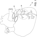
- FIG. 1 is a somewhat stylized representation of a human heart 50.
- Heart 50 includes a plurality of coronary arteries 52, all of which are susceptible to occlusion. Under certain physiological circumstances and given sufficient time, some occlusions may become total or complete, such as total occlusion 36 shown in figure 1 .
- total occlusion and complete occlusion are intended to refer to the same or similar degree of occlusion with some possible variation in the age of the occlusion.
- a total occlusion refers to a vascular lumen that is ninety percent or more functionally occluded in cross-sectional area, rendering it with little to no blood flow therethrough and making it difficult or impossible to pass a conventional guide wire therethrough.
- the older the total occlusion the more organized the occlusive material will be and the more fibrous and calcified it will become. According to one accepted clinical definition, a total occlusion is considered chronic if it is greater than two weeks old from symptom onset.
- FIG. 2 is an enlarged view further illustrating a portion of heart 50 shown in the previous figure.
- a total occlusion 36 is shown within a coronary artery 52.
- the proximal segment 32 of artery 52 i.e., the portion of artery 52 proximal of total occlusion 36
- the distal segment 34 of artery 52 i.e., the portion of artery 52 distal of total occlusion 36
- distal segment 34 has significantly reduced blood flow as compared to proximal segment 32.
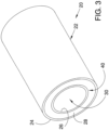
- FIG 3 is a perspective view of an artery 20 having a wall 22.
- wall 22 of artery 20 is shown having three layers.
- the outermost layer of wall 22 is the adventitia 24 and the innermost layer of wall 22 is the intima 26.
- Intima 26 defines a true lumen 30 of artery 20.
- the tissues extending between intima 26 and adventitia 24 may be collectively referred to as the media 28.
- intima 26, media 28 and adventitia 24 are each shown as a single homogenous layer in figure 3 .
- the intima and the media each comprise a number of sub-layers.
- the transition between the external most portion of the intima and the internal most portion of the media is sometimes referred to as the subintimal space 40.
- the subintimal space 40 has a generally annular shape with its radial center at the center of the true lumen.
- Some of the devices and methods discussed in this detailed description may take advantage of the position and geometry of the subintimal space 40 relative to the true lumen of the blood vessel.
- some orienting devices described herein may be adapted to orient themselves within that space. Once the orientation of the orienting device is established, the orienting device may be used to direct a re-entry device toward the true lumen.
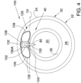
- Figure 4 is a lateral cross-sectional view of artery 20 shown in the previous figure.
- an orienting device 100 is shown disposed between adventitia 24 and intima 26 of artery 20.
- Orienting device 100 comprises a distal shaft 102 having an outer wall 128 defining a central lumen 104.
- Orienting device 100 comprises an orienting element 120 that is coupled to distal shaft 102.
- orienting element 120 comprises an inflatable member 126.
- the top of inflatable member 126 may be fixed to distal shaft 102, for example, at a first interface 190A.
- the bottom of inflatable member 126 may be fixed to distal shaft 102, for example, at a second interface 190B.
- Orienting element 120 comprises a first portion 106 and a second portion 108.
- First portion 106 of orienting element 120 extends in a first direction away from distal shaft 102.
- Second portion 108 of orienting element 120 extends away from distal shaft 102 in a second direction that is generally opposite the first direction.
- Distal shaft 102 defines a first aperture 130 and a second aperture 132.
- First aperture 130 extends in a third direction through distal shaft 102.
- Second aperture 132 extends through distal shaft 102 in a forth direction that is generally opposite the third direction.
- First aperture 130 and second aperture 132 are generally oriented at a right angle to a tangent plane TP.
- tangent plane TP is tangent to subintimal space 40.
- first aperture 130 and second aperture 132 may be facing
- This may be conceptualized in terms of degrees of freedom.
- the number of directions that an aperture may be facing is reduced from 360 degrees of freedom to two degrees of freedom, 180 degrees apart.
- orienting device 100 When inflatable member 126 of orienting element 120 is inflated between adventitia 24 and intima 26 of artery 20 orienting device 100 will orient itself within artery 20 so that either first aperture 130 or second aperture 132 opens toward a true lumen 30 of artery 20.
- orienting device 100 has been positioned so that first aperture 130 opens toward intima 26 of artery 20 and second aperture 132 opens toward adventitia 24.
- a re-entry device 180 is shown extending through first aperture 130 and intima 26. A distal end of re-entry device 180 is disposed in true lumen 30 of blood vessel 20.
- Orienting device 100 and re-entry device 180 may be used to establish fluid communication between a proximal segment and a distal segment that are separated by an occlusion. Exemplary methods for establishing this fluid communication will be described below.
- Figure 5 is a longitudinal cross-sectional view of an artery 20 having an occlusion 36 blocking true lumen 30 thereof.
- Occlusion 36 divides true lumen 30 into a proximal segment 32 and a distal segment 34.
- a distal portion of a guidewire 60 is shown extending into proximal segment 32 of true lumen 30.
- the methods described in this document may include the step of advancing a guidewire to a location proximate an occlusion in a blood vessel.
- the exemplary methods described in this document may also include the step of advancing guidewire 60 between occlusion 36 and adventitia 24 of wall 22.
- the guidewire may be used to guide additional endovascular devices to a location proximate occlusion 36.
- Figure 6 is an additional cross-sectional view of artery 20 shown in the previous figure.
- a crossing device 70 has been advanced over guidewire 60 so that a distal portion of crossing device 70 is disposed in proximal segment 32 of true lumen 30.
- Crossing device 70 of figure 6 comprises a tip 74 that is fixed to a distal end of a shaft 72.
- Crossing device 70 may be used in conjunction with a method for establishing a channel between proximal segment 32 and distal segment 34. The methods described in this document may include the step of advancing a crossing device over a guidewire.
- crossing device 70 may be rotated about it's longitudinal axis and moved in a direction parallel to it's longitudinal axis simultaneously. When this is the case, rotation of crossing device 70 may reduce resistance to the axial advancement of crossing device 70.
- These methods take advantage of the fact that the kinetic coefficient of friction is usually less than the static coefficient of friction for a given frictional interface. Rotating crossing device 70 assures that the coefficient of friction at the interface between the crossing device and the surround tissue will be a kinetic coefficient of friction and not a static coefficient of friction.
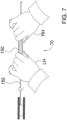
- Figure 7 is a plan view showing an assembly including crossing device 70 shown in the previous figure.
- a handle assemlby 76 is coupled to crossing device 70.
- handle assemlby 76 is shown disposed about a proximal portion of a shaft 152 of crossing device 70.
- a portion of handle assembly 76 is positioned between the thumb and forefinger of a left hand LH.
- a second portion of handle assemlby 76 is disposed between the thumb and forefinger of a right hand RH.
- handle assemlby 76 is long enough to receive the thumb and forefingers of a physician's right and left hands. When this is the case, a physician can use two hands to rotate handle assemlby 76.
- Rotation of crossing device 70 can be achieved by rolling handle assemlby 76 between the thumb and forefinger of one hand. Two hands may also be used to rotate handle assemlby 76 as shown in figure 7 . In some useful methods, crossing device 70 can be rotated and axially advanced simultaneously.
- crossing device 70 is rotated at a rotational speed of between about 2 revolutions per minute and about 200 revolutions per minute. In some particularly useful methods in accordance with the present disclosure, crossing device 70 is rotated at a rotational speed of between about 50 revolutions per minute and about 150 revolutions per minute.
- Crossing device 70 may be rotated by hand as depicted in figure 7 . It is also contemplated that a mechanical device (e.g., an electric motor) may be used to rotate crossing device 70. Rotating crossing device 70 assures that the coefficient of friction at the interface between the crossing device and the surround tissue will be a kinetic coefficient of friction and not a static coefficient of friction.
- a mechanical device e.g., an electric motor
- Figure 8 is an additional longitudinal cross-sectional view of artery 20.
- the distal end of crossing device 70 has been advanced in a distal direction so that tip 74 is adjacent occlusion 36.
- tip 74 has passed beyond intima 26 and is disposed between occlusion 36 and adventitia 24 of artery 20.
- Exemplary methods described in this document may include the step of advancing a crossing device between an occlusion and the adventitia of an artery.
- Figure 9 is an additional view of artery 20 and crossing device 70 shown in the previous figure.
- the distal end of crossing device 70 has been advanced in an axial direction past occlusion 36.
- Exemplary methods described herein may include the step of advancing a crossing device beyond an occlusion.
- crossing device has crossed occlusion 36 by advancing between occlusion 36 and adventitia 24 of wall 22.
- the crossing device 70 may pass through occlusion 36 while remaining disposed inside true lumen 30.
- tip 74 of crossing device 70 is shown residing between intima 26 and adventitia 24 of artery 20. As tip 74 moves in an axial direction between intima 26 and adventitia 24, tip 74 may cause blunt dissection of the layers forming wall 22 of artery 20. Alternatively, tip 74 may cause blunt dissection of the materials comprising the occlusion 36.
- tip 74 of crossing device 70 is disposed between intima 26 and adventitia 24.
- fluid communication between proximal segment 32 and distal segment 34 may be achieved by creating an opening through intima 26.
- Such an opening may be created, for example, using a re-entry device and an orienting device that directs the advancement of the re-entry device toward intima 26.
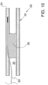
- Figure 10 is an additional view of artery 20 shown in the previous figure.
- crossing device 70 has been withdrawn from true lumen 30 of artery 20.
- guidewire 60 remains in the position formerly occupied by crossing device 70.
- the position of guidewire 60 shown in figure 10 may be achieved using crossing device 70.
- Guidewire 60 may be positioned, for example, by first placing crossing device 70 in the position shown in the previous figure, then advancing guidewire 60 through lumen 122 defined by shaft 72 of crossing device 70. Alternately, guidewire 60 may be disposed within lumen 122 while crossing device 70 is advanced beyond occlusion 36.
- guidewire 60 may be used to direct other devices between occlusion 36 and adventitia 24.
- a catheter may be advanced over guidewire 60 until the distal end of the catheter extends between an occlusion and the adventia. After reaching this location, the catheter may be used to dilate the tissue surrounding the catheter. Examples of catheters that may be used to dilate tissue include balloon angioplasty catheters, atherectomy catheters, and stent delivery catheters.
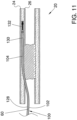
- Figure 11 is an additional view of artery 20 and guidewire 60 shown in the previous figure.
- an orienting device 100 has been advanced over guidewire 60.
- Orienting device 100 includes a distal shaft 102 comprising a outer wall 128 defining a central lumen 104.
- a first aperture 130 and a second aperture 132 are also defined by outer wall 128.
- first aperture 130 and second aperture 132 are both in fluid communication with central lumen 104.
- orienting device 100 has been positioned so that first aperture 130 opens toward intima 26 of artery 20 and second aperture 132 opens toward adventitia 24.
- first aperture 130 and second aperture 132 are longitudinally separated from one another.
- Orienting device 100 includes a first radiopaque marker that is located between first aperture 130 and second aperture 132.
- a second radiopaque marker of orienting device 100 is located distally of second aperture 132.
- Figure 12 is an additional view of artery 20 and orienting device 100 shown in the previous figure.
- guidewire 60 has been withdrawn leaving orienting device 100 in the position shown in figure 12 .
- orienting device 100 extends beyond occlusion 36.
- occlusion 36 is shown blocking true lumen 30.
- Occlusion 36 divides true lumen 30 into a proximal segment 32 and a distal segment 34.
- the orienting device may be used to direct a re-entry device toward true lumen 30. Fluid communication between proximal segment 32 and distal segment 34 may be achieved by re-entering the true lumen with a re-entry device.
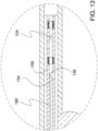
- Figure 13 is an enlarged partial cross-sectional view showing a portion of orienting device 100 shown in the previous figure.
- a re-entry device 180 has been advanced into central lumen 104 of orienting device 100.
- re-entry device 180 includes a bend 134 near distal end 136 of re-entry device 180.
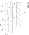
- Figure 14 is an additional partial cross-sectional view showing a portion of re-entry device 180 and orienting device 100.
- figure 14 is enlarged and simplified relative to the items shown in the previous figure.
- re-entry device 180 is biased to assume a bent shape including a bend 134.
- distal shaft 102 of orienting device 100 is holding re-entry device 180 in a somewhat compressed state.
- re-entry device 180 can be inserted through first aperture 130 by positioning distal end 136 over first aperture 130 and allowing bend 134 to assume it's natural state (i.e., bent at a sharper angle).
- Re-entry device 180 can be inserted through first aperture 130 until it comes into contact with intima 26.
- distal end 136 of re-entry device 180 is axially aligned with first aperture 130, however, bend 134 is causing distal end 136 to point away from first aperture 130.
- distal end 136 may be positioned over first aperture 130 by rotating re-entry device 180 central lumen 104 of orienting device 100.
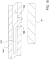
- Figure 15 is an enlarged partial cross-sectional view showing a portion of re-entry device 180 and orienting device 100 shown in the previous figure.
- re-entry device 180 has been positioned so that a distal portion of reentry device 180 has entered first aperture 130.
- Intima 26 is shown below first aperture 130 in figure 15 .
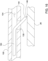
- Figure 16 is an enlarged partial cross-sectional view showing a portion of re-entry device 180 and intima 26.
- re-entry device 180 is shown extending through central lumen 104 and first aperture 130.
- re-entry device 180 comprises a distal surface 144 and a probe 146 extending beyond distal surface 144.
- probe 146 of re-entry device 180 is contacting intima 26.
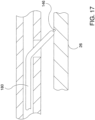
- Figure 17 is an enlarged partial cross-sectional view showing a portion of re-entry device 180.
- probe 146 of re-entry device 180 has pierced intima 26.
- probe 146 may anchor the distal tip of re-entry device 180 to intima 26. Additionally, the piercing of intima 26 with probe 146 may serve to weaken intima 26.
- Figure 18 is an enlarged partial cross-sectional view showing a portion of re-entry device 180.
- the distal end 136 of re-entry device 180 has been advanced through intima 26.
- distal end 136 of re-entry device 180 is disposed in true lumen 30 defined by intima 26.
- Figure 19 is a partial cross-sectional view of re-entry device 180 shown in the previous figure.
- Figure 19 has a different scale than the previous figure so that more of the surrounding context is visible in figure 19 .
- distal end 136 of re-entry device 180 can be seen residing in true lumen 30.
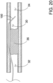
- Figure 20 is an additional view of artery 20 shown in the previous figure.
- orienting device 100 has been withdrawn leaving re-entry device 180 in the position shown in figure 20 .
- Devices such as balloon angioplasty catheters, atherectomy catheters, and stent delivery catheters may be advanced over re-entry device 180. In this way, these devices may be used in conjunction with re-entry device 180 to establish a blood flow path between proximal segment 32 of true lumen 30 and distal segment 34 of true lumen 30. This path allows blood to flow around occlusion 36.
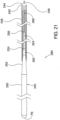
- FIG 21 is a partial cross-sectional view of an exemplary re-entry device 280 in accordance with the present detailed description.
- Re-entry device 280 comprises a tip member 242 that is fixed to a shaft 240 and a coil 248 that is disposed about a distal portion of the shaft 240.
- Shaft 240 comprises a proximal segment 250 that extends between a proximal end PE and a first tapered segment 252.
- coil 248 extends between first tapered segment 252 and tip member 242.
- a first intermediate segment 262 of shaft 240 extends between first tapered segment 252 and a second tapered segment 254.
- a second intermediate segment 264 of shaft 240 extends between second tapered segment 254 and a third tapered segment 256.
- a distal segment 260 of shaft 240 extends between third tapered segment 256 and tip member 242.
- tip member 242 is fixed to distal segment 260 of shaft 240.
- a probe 246 of re-entry device 280 extends distally beyond a distal surface 244 of tip member 242.
- FIG 22 is a plan view of an exemplary re-entry device 380 in accordance with the present detailed description.
- Re-entry device 380 comprises a tip member 342 having a distal surface 344.
- distal surface 344 of tip member has a generally convex shape.
- tip member 342 may have a generally hemispherical shape.
- a probe 346 of re-entry device 380 extends distally beyond distal surface 344. Probe 346 terminates at a distal face 358.
- distal face 358 is shown as a straight line representing a substantially flat surface. With reference to figure 22 , it will be appreciated that distal face 358 is substantially perpendicular to the longitudinal axis of probe 346.
- length L of probe 346 is between about 0.003 inches and about 0.032 inches.
- a coil 348 is shown extending between tip member 342 and a first tapered segment 352.
- Shaft 340 comprises a proximal segment 350 that extends between a proximal end PE and a first tapered segment 352.
- FIG. 23 is a partial cross-sectional view of an exemplary re-entry device 480 in accordance with the present detailed description.
- Re-entry device 480 comprises a tip member 442 that is fixed to a distal segment 460 of a shaft 440.
- tip member 442 comprises a distal surface 444 and a probe 446 extending distally beyond distal surface 444.
- distal surface 444 of tip member has a generally hemispherical shape and probe 446 has a generally cylindrical shape terminating at a flat distal face 458.
- distal face 458 is substantially perpendicular to the longitudinal axis of probe 446.
- a tip member having a shape similar to tip member 442 shown in figure 23 .
- a tip member may be formed, for example, using various manufacturing processes such as, for example, casting and molding.
- a tip member may also be fabricated by a manufacturing process comprising removing material from a piece of stock material to produce a desired profile. Examples of processes that may be used to remove material from a piece of stock material include grinding and machining (e.g., turning on a lathe).
- probe 446 extends beyond distal surface 444 of tip member 442 by a distance L. Also in the embodiment of Figure 23 , probe 446 has a diameter DA and tip member 442 has a diameter DB. In some useful embodiments, the these dimensions fall with the numerical ranges mentioned in the detailed description of figure 22 .
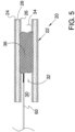
- FIG 24 is a partial cross-sectional view of an exemplary re-entry device 580 in accordance with the present detailed description.
- Re-entry device 580 comprises a shaft 540 and a tip member 542 that is fixed to a distal segment 560 of shaft 540.
- a probe 546 of re-entry device 580 extends distally beyond a distal surface 544 of tip member 542.
- probe 546 comprises a portion of distal segment 560 that extends beyond distal surface 544.
- a coil 548 of re-entry device 580 extends between tip member 542 and a first tapered segment 552 of shaft 540. Coil 548 is fixed to first tapered section 552 at a joint 566.
- Joint 566 and tip member 542 may comprise, for example, silver (e.g., silver solder and/or silver braze). Joint 566 and tip member 542 may be formed using various manufacturing processes (e.g., soldering, brazing, and welding).
- distal segment 560 of shaft 540 terminates at a substantially flat distal face 558.
- Probe 546 comprises a portion of distal segment 560 that extends beyond distal surface 544 of tip member 542 by a distance L. Also in the embodiment of Figure 24 , probe 546 has a diameter DA and tip member 542 has a diameter DB. In some useful embodiments, the these dimensions fall with the numerical ranges mentioned in the detailed description of figure 22 .
- FIG 25 is a plan view of an exemplary re-entry device 680 in accordance with the present detailed description.
- Re-entry device 680 comprises a tip member 642 having a distal surface 644.
- distal surface 644 of tip member has a generally convex shape.
- tip member 642 may have a generally hemispherical shape.
- a probe 646 of re-entry device 680 extends distally beyond distal surface 644. Probe 646 terminates at a distal face 658.
- distal face 658 is shown as a straight line representing a substantially flat surface.
- re-entry device 600 is shown being bent at an angle A. Accordingly, it can be said that re-entry device 600 includes a bend 630. In some useful embodiments of re-entry device 600, angle A is between about 90 degrees and about 180 degrees. In some particularly useful embodiments of re-entry device 600, angle A is between about 120 degrees and about 150 degrees. Re-entry device 680 has a distal leg 668 disposed distally of bend 634 and a proximal leg 670 disposed proximally of bend 634.
- FIG 26 is a cross-sectional view of an exemplary re-entry device 780 in accordance with the present invention.
- Re-entry device 780 comprises a core wire 772 and a jacket 774 that is disposed about a portion of core wire 772.
- Jacket 774 terminates at a distal surface 744.
- a probe 746 of re-entry device 780 extends distally beyond distal surface 744.
- probe 746 comprises a distal segment 760 of core wire 772.
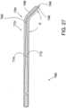
- FIG. 27 is a cross-sectional view of an exemplary re-entry device 780 in accordance with the present invention.
- Re-entry device 780 comprises a core wire 772 and a jacket 774 that is disposed about a portion of core wire 772.
- re-entry device 780 includes a bend 734 near its distal end.
- Re-entry device 780 has a distal leg 768 disposed distally of bend 734 and a proximal leg 770 disposed proximally of bend 734.
- Distal leg 768 and proximal leg 770 define an angle A. In some useful embodiments of re-entry device 700, angle A is between about 90 degrees and about 180 degrees.
- angle A is between about 120 degrees and about 150 degrees.
- Jacket 774 of re-entry device 780 terminates at a distal surface 744.
- a probe 746 of re-entry device 780 extends distally beyond distal surface 744.
- probe 746 comprises a distal segment 760 of core wire 772.
Landscapes
- Health & Medical Sciences (AREA)
- Life Sciences & Earth Sciences (AREA)
- Surgery (AREA)
- General Health & Medical Sciences (AREA)
- Public Health (AREA)
- Engineering & Computer Science (AREA)
- Biomedical Technology (AREA)
- Heart & Thoracic Surgery (AREA)
- Veterinary Medicine (AREA)
- Animal Behavior & Ethology (AREA)
- Medical Informatics (AREA)
- Nuclear Medicine, Radiotherapy & Molecular Imaging (AREA)
- Molecular Biology (AREA)
- Vascular Medicine (AREA)
- Pulmonology (AREA)
- Hematology (AREA)
- Biophysics (AREA)
- Anesthesiology (AREA)
- Pathology (AREA)
- Media Introduction/Drainage Providing Device (AREA)
- Surgical Instruments (AREA)
Description
- The inventions described herein relate to devices for the treatment of chronic total occlusions. More particularly, the inventions described herein relate to devices for crossing chronic total occlusions and establishing a pathway blood flow past the chronic total occlusions.
- Due to age, high cholesterol and other contributing factors, a large percentage of the population has arterial atherosclerosis that totally occludes portions of the patient's vasculature and presents significant risks to patient health. For example, in the case of a total occlusion of a coronary artery, the result may be painful angina, loss of cardiac tissue or patient death. In another example, complete occlusion of the femoral and/or popliteal arteries in the leg may result in limb threatening ischemia and limb amputation.
- Commonly known endovascular devices and techniques are either inefficient (time consuming procedure), have a high risk of perforating a vessel (poor safety) or fail to cross the occlusion (poor efficacy). Physicians currently have difficulty visualizing the native vessel lumen, can not accurately direct endovascular devices toward the visualized lumen, or fail to advance devices through the lesion. Bypass surgery is often the preferred treatment for patients with chronic total occlusions, but less invasive techniques would be preferred.
-
- The invention is defined in the independent claims. Further embodiments are defined in the dependent claims. Devices, systems and exemplary methods for treating diseases and disorders effecting the cardiovascular system of the human body are disclosed. An exemplary blood vessel in accordance with this disclosure comprises a shaft, tip member fixed to the shaft, and a probe extending beyond a distal surface of the tip member. In some useful embodiments, the tip member is relatively atraumatic and the probe is shaped so as to be more likely to produce trauma than the tip member. Surgical methods are not claimed.
-
-
Figure 1 is a somewhat stylized representation of a human heart. The heart includes a plurality of coronary arteries, all of which are susceptible to occlusion. -
Figure 2 is an enlarged view further illustrating a portion of the heart shown in the previous figure. Infigure 2 , a total occlusion is shown within a coronary artery. -
Figure 3 is a perspective view of a blood vessel (e.g., a coronary artery). Infigure 3 , the wall of the blood vessel is shown having three layers (the intima, the media, and the adventitia). -
Figure 4 is a lateral cross-sectional view of the artery shown in the previous figure. Infigure 4 , an orienting device is shown disposed between the adventitia and the intima of the artery. -
Figure 5 is a longitudinal cross-sectional view of an artery having an occlusion blocking the true lumen. -
Figure 6 is an additional cross-sectional view of the artery shown in the previous figure. In the embodiment offigure 6 , a crossing device has been advanced over a guidewire so that a distal portion of crossing device is disposed in proximal segment of the true lumen. -
Figure 7 is a plan view showing an assembly including crossing device shown in the previous figure. -
Figure 8 is an additional view of an artery. In the embodiment offigure 8 , the distal end of the crossing device has been advanced in a distal direction so that the tip of the crossing device is adjacent an occlusion that is blocking the true lumen of the artery. -
Figure 9 is an additional view of the artery and the crossing device shown in the previous figure. In the embodiment offigure 9 , the distal end of the crossing device has been advanced between the intima and the adventitia of the wall of the artery. -
Figure 10 is an additional view of the artery shown in the previous figure. In the embodiment offigure 10 , the crossing device has been withdrawn and a guidewire remains in the position formerly occupied by the crossing device. -
Figure 11 is an additional view of the artery and the guidewire shown in the previous figure. In the embodiment offigure 11 , anorienting device 100 been advanced over the guidewire. -
Figure 12 is an additional view of the artery and the orienting device shown in the previous figure. -
Figure 13 is an enlarged partial cross-sectional view showing a portion of the orienting device shown in the previous figure. In the embodiment offigure 13 , a re-entry device has been advanced into the central lumen of orienting device. -
Figure 14 is an additional partial cross-sectional view showing a portion of the re-entry device and the orienting device shown infigure 13 . For purposes of illustration,figure 14 is enlarged and simplified relative to the items shown infigure 13 . -
Figure 15 is an enlarged partial cross-sectional view showing a portion of the re-entry device and the orienting device shown in the previous figure. In the embodiment offigure 15 , the re-entry device has been positioned so that a distal portion of the re-entry device has entered the first aperture of the orienting device. -
Figure 16 is an enlarged partial cross-sectional view showing a portion of a re-entry device and the intima of a blood vessel. In the embodiment offigure 16 , a probe of the re-entry device is contacting the intima. -
Figure 17 is an enlarged partial cross-sectional view showing a portion of the re-entry device shown in the previous figure. In the embodiment offigure 17 , the probe of the re-entry device has pierced the intima of the blood vessel. When this is the case, the probe may anchor the distal tip of the re-entry device to the intima. Additionally, the piercing of the intima with the probe may serve to weaken the intima. -
Figure 18 is an enlarged partial cross-sectional view showing a portion of the re-entry device shown in the previous figure. In the embodiment offigure 18 , the distal end of the re-entry device has been advanced through the intima of a blood vessel and is disposed in the true lumen of the blood vessel. -
Figure 19 is a partial cross-sectional view of the re-entry device shown in the previous figure.Figure 19 has a different scale than the previous figure so that more of the surrounding context is visible infigure 19 . Infigure 19 , the distal end of the re-entry device can be seen residing in the true lumen of the blood vessel. -
Figure 20 is an additional view of the blood vessel shown in the previous figure. In the embodiment offigure 20 , the orienting device has been withdrawn leaving the re-entry device in the position shown infigure 20 . Devices such as balloon angioplasty catheters, atherectomy catheters, and stent delivery catheters may be advanced over the re-entry device. In this way, these devices may be used in conjunction with the re-entry device to establish a blood flow path between around an occlusion in a blood vessel. -
Figure 21 is a partial cross-sectional view of an exemplary re-entry device. -
Figure 22 is a plan view of an exemplary re-entry device. -
Figure 23 is a partial cross-sectional view of an exemplary re-entry device. -
Figure 24 is a partial cross-sectional view of an exemplary re-entry device. -
Figure 25 is a plan view of an exemplary re-entry device. -
Figure 26 is a cross-sectional view of an exemplary re-entry device, in accordance with the present invention. -
Figure 27 is a cross-sectional view of an exemplary re-entry device, in accordance with the present invention. - The following detailed description should be read with reference to the drawings in which similar elements in different drawings are numbered the same. The drawings, which are not necessarily to scale, depict illustrative embodiments and are not intended to limit the scope of the invention.
-
Figure 1 is a somewhat stylized representation of ahuman heart 50.Heart 50 includes a plurality ofcoronary arteries 52, all of which are susceptible to occlusion. Under certain physiological circumstances and given sufficient time, some occlusions may become total or complete, such astotal occlusion 36 shown infigure 1 . - As used herein, the terms total occlusion and complete occlusion are intended to refer to the same or similar degree of occlusion with some possible variation in the age of the occlusion. Generally, a total occlusion refers to a vascular lumen that is ninety percent or more functionally occluded in cross-sectional area, rendering it with little to no blood flow therethrough and making it difficult or impossible to pass a conventional guide wire therethrough. Also generally, the older the total occlusion the more organized the occlusive material will be and the more fibrous and calcified it will become. According to one accepted clinical definition, a total occlusion is considered chronic if it is greater than two weeks old from symptom onset.
-
Figure 2 is an enlarged view further illustrating a portion ofheart 50 shown in the previous figure. Infigure 2 , atotal occlusion 36 is shown within acoronary artery 52. Generally, theproximal segment 32 of artery 52 (i.e., the portion ofartery 52 proximal of total occlusion 36) has adequate blood flow to supply the surrounding cardiac muscle and may be easily accessed using endovascular devices. In contrast, thedistal segment 34 of artery 52 (i.e., the portion ofartery 52 distal of total occlusion 36) is not easily accessed with interventional devices. Additionally,distal segment 34 has significantly reduced blood flow as compared toproximal segment 32. -
Figure 3 is a perspective view of anartery 20 having awall 22. Infigure 3 ,wall 22 ofartery 20 is shown having three layers. The outermost layer ofwall 22 is theadventitia 24 and the innermost layer ofwall 22 is theintima 26.Intima 26 defines atrue lumen 30 ofartery 20. The tissues extending betweenintima 26 andadventitia 24 may be collectively referred to as themedia 28. For purposes of illustration,intima 26,media 28 andadventitia 24 are each shown as a single homogenous layer infigure 3 . In the human body, however, the intima and the media each comprise a number of sub-layers. The transition between the external most portion of the intima and the internal most portion of the media is sometimes referred to as thesubintimal space 40. - With reference to
figure 3 , it will be appreciated that thesubintimal space 40 has a generally annular shape with its radial center at the center of the true lumen. Some of the devices and methods discussed in this detailed description may take advantage of the position and geometry of thesubintimal space 40 relative to the true lumen of the blood vessel. For example, some orienting devices described herein may be adapted to orient themselves within that space. Once the orientation of the orienting device is established, the orienting device may be used to direct a re-entry device toward the true lumen. -
Figure 4 is a lateral cross-sectional view ofartery 20 shown in the previous figure. Infigure 4 , anorienting device 100 is shown disposed betweenadventitia 24 andintima 26 ofartery 20.Orienting device 100 comprises adistal shaft 102 having anouter wall 128 defining acentral lumen 104.Orienting device 100 comprises an orientingelement 120 that is coupled todistal shaft 102. - In the embodiment of
figure 4 , orientingelement 120 comprises aninflatable member 126. The top ofinflatable member 126 may be fixed todistal shaft 102, for example, at afirst interface 190A. The bottom ofinflatable member 126 may be fixed todistal shaft 102, for example, at a second interface 190B. - Orienting
element 120 comprises afirst portion 106 and asecond portion 108.First portion 106 of orientingelement 120 extends in a first direction away fromdistal shaft 102.Second portion 108 of orientingelement 120 extends away fromdistal shaft 102 in a second direction that is generally opposite the first direction. -
Distal shaft 102 defines afirst aperture 130 and asecond aperture 132.First aperture 130 extends in a third direction throughdistal shaft 102.Second aperture 132 extends throughdistal shaft 102 in a forth direction that is generally opposite the third direction.First aperture 130 andsecond aperture 132 are generally oriented at a right angle to a tangent plane TP. Infigure 4 , tangent plane TP is tangent to subintimalspace 40. - When
inflatable member 126 is inflated, the number of directions thatfirst aperture 130 andsecond aperture 132 may be facing is reduced. This may be conceptualized in terms of degrees of freedom. Wheninflatable member 126 of orientingelement 120 is inflated, the number of directions that an aperture may be facing is reduced from 360 degrees of freedom to two degrees of freedom, 180 degrees apart. - When
inflatable member 126 of orientingelement 120 is inflated betweenadventitia 24 andintima 26 ofartery 20orienting device 100 will orient itself withinartery 20 so that eitherfirst aperture 130 orsecond aperture 132 opens toward atrue lumen 30 ofartery 20. In the embodiment offigure 4 , orientingdevice 100 has been positioned so thatfirst aperture 130 opens towardintima 26 ofartery 20 andsecond aperture 132 opens towardadventitia 24. Infigure 4 , are-entry device 180 is shown extending throughfirst aperture 130 andintima 26. A distal end ofre-entry device 180 is disposed intrue lumen 30 ofblood vessel 20.Orienting device 100 andre-entry device 180 may be used to establish fluid communication between a proximal segment and a distal segment that are separated by an occlusion. Exemplary methods for establishing this fluid communication will be described below. -
Figure 5 is a longitudinal cross-sectional view of anartery 20 having anocclusion 36 blockingtrue lumen 30 thereof.Occlusion 36 dividestrue lumen 30 into aproximal segment 32 and adistal segment 34. Infigure 5 , a distal portion of aguidewire 60 is shown extending intoproximal segment 32 oftrue lumen 30. The methods described in this document may include the step of advancing a guidewire to a location proximate an occlusion in a blood vessel. The exemplary methods described in this document may also include the step of advancingguidewire 60 betweenocclusion 36 andadventitia 24 ofwall 22. In some cases, however, the nature of the occlusion and the blood vessel will be such that the guidewire is unlikely to advance beyond the occlusion. When this is the case, the guidewire may be used to guide additional endovascular devices to a locationproximate occlusion 36. -
Figure 6 is an additional cross-sectional view ofartery 20 shown in the previous figure. In the embodiment offigure 6 , acrossing device 70 has been advanced overguidewire 60 so that a distal portion of crossingdevice 70 is disposed inproximal segment 32 oftrue lumen 30. Crossingdevice 70 offigure 6 comprises atip 74 that is fixed to a distal end of ashaft 72. Crossingdevice 70 may be used in conjunction with a method for establishing a channel betweenproximal segment 32 anddistal segment 34. The methods described in this document may include the step of advancing a crossing device over a guidewire. - In some exemplary methods in accordance with the present disclosure, crossing
device 70 may be rotated about it's longitudinal axis and moved in a direction parallel to it's longitudinal axis simultaneously. When this is the case, rotation of crossingdevice 70 may reduce resistance to the axial advancement of crossingdevice 70. These methods take advantage of the fact that the kinetic coefficient of friction is usually less than the static coefficient of friction for a given frictional interface. Rotating crossingdevice 70 assures that the coefficient of friction at the interface between the crossing device and the surround tissue will be a kinetic coefficient of friction and not a static coefficient of friction. -
Figure 7 is a plan view showing an assembly including crossingdevice 70 shown in the previous figure. In the embodiment offigure 7 , a handle assemlby 76 is coupled to crossingdevice 70. Infigure 7 , handle assemlby 76 is shown disposed about a proximal portion of ashaft 152 of crossingdevice 70. Infigure 7 , a portion of handle assembly 76 is positioned between the thumb and forefinger of a left hand LH. A second portion of handle assemlby 76 is disposed between the thumb and forefinger of a right hand RH. With reference tofigure 7 , it will be appreciated that handle assemlby 76 is long enough to receive the thumb and forefingers of a physician's right and left hands. When this is the case, a physician can use two hands to rotate handle assemlby 76. - Rotation of crossing
device 70 can be achieved by rolling handle assemlby 76 between the thumb and forefinger of one hand. Two hands may also be used to rotate handle assemlby 76 as shown infigure 7 . In some useful methods,crossing device 70 can be rotated and axially advanced simultaneously. - in some exemplary methods in accordance with the present disclosure, crossing
device 70 is rotated at a rotational speed of between about 2 revolutions per minute and about 200 revolutions per minute. In some particularly useful methods in accordance with the present disclosure, crossingdevice 70 is rotated at a rotational speed of between about 50 revolutions per minute and about 150 revolutions per minute. - Crossing
device 70 may be rotated by hand as depicted infigure 7 . It is also contemplated that a mechanical device (e.g., an electric motor) may be used to rotate crossingdevice 70. Rotating crossingdevice 70 assures that the coefficient of friction at the interface between the crossing device and the surround tissue will be a kinetic coefficient of friction and not a static coefficient of friction. -
Figure 8 is an additional longitudinal cross-sectional view ofartery 20. In the embodiment offigure 8 , the distal end of crossingdevice 70 has been advanced in a distal direction so thattip 74 isadjacent occlusion 36. With reference tofigure 8 , it will be appreciated thattip 74 has passed beyondintima 26 and is disposed betweenocclusion 36 andadventitia 24 ofartery 20. Exemplary methods described in this document may include the step of advancing a crossing device between an occlusion and the adventitia of an artery. -
Figure 9 is an additional view ofartery 20 andcrossing device 70 shown in the previous figure. In the embodiment offigure 9 , the distal end of crossingdevice 70 has been advanced in an axial direction pastocclusion 36. Exemplary methods described herein may include the step of advancing a crossing device beyond an occlusion. In the embodiment offigure 9 , crossing device has crossedocclusion 36 by advancing betweenocclusion 36 andadventitia 24 ofwall 22. - It is to be appreciated that other exemplary methods of crossing an occlusion are within the scope of this disclosure. For example, the crossing
device 70 may pass throughocclusion 36 while remaining disposed insidetrue lumen 30. Infigure 9 ,tip 74 of crossingdevice 70 is shown residing betweenintima 26 andadventitia 24 ofartery 20. Astip 74 moves in an axial direction betweenintima 26 andadventitia 24,tip 74 may cause blunt dissection of thelayers forming wall 22 ofartery 20. Alternatively,tip 74 may cause blunt dissection of the materials comprising theocclusion 36. - In the embodiment of
figure 9 ,tip 74 of crossingdevice 70 is disposed betweenintima 26 andadventitia 24. When this is the case, fluid communication betweenproximal segment 32 anddistal segment 34 may be achieved by creating an opening throughintima 26. Such an opening may be created, for example, using a re-entry device and an orienting device that directs the advancement of the re-entry device towardintima 26. -
Figure 10 is an additional view ofartery 20 shown in the previous figure. In the embodiment offigure 10 , crossingdevice 70 has been withdrawn fromtrue lumen 30 ofartery 20. With reference tofigure 10 , it will be appreciated thatguidewire 60 remains in the position formerly occupied by crossingdevice 70. - The position of
guidewire 60 shown infigure 10 may be achieved usingcrossing device 70.Guidewire 60 may be positioned, for example, by first placingcrossing device 70 in the position shown in the previous figure, then advancingguidewire 60 through lumen 122 defined byshaft 72 of crossingdevice 70. Alternately, guidewire 60 may be disposed within lumen 122 while crossingdevice 70 is advanced beyondocclusion 36. - With
guidewire 60 in the position shown infigure 10 , guidewire 60 may be used to direct other devices betweenocclusion 36 andadventitia 24. For example, a catheter may be advanced overguidewire 60 until the distal end of the catheter extends between an occlusion and the adventia. After reaching this location, the catheter may be used to dilate the tissue surrounding the catheter. Examples of catheters that may be used to dilate tissue include balloon angioplasty catheters, atherectomy catheters, and stent delivery catheters. -
Figure 11 is an additional view ofartery 20 and guidewire 60 shown in the previous figure. In the embodiment offigure 11 , anorienting device 100 has been advanced overguidewire 60.Orienting device 100 includes adistal shaft 102 comprising aouter wall 128 defining acentral lumen 104. Afirst aperture 130 and asecond aperture 132 are also defined byouter wall 128. In the embodiment offigure 11 ,first aperture 130 andsecond aperture 132 are both in fluid communication withcentral lumen 104. - In the embodiment of
figure 11 , orientingdevice 100 has been positioned so thatfirst aperture 130 opens towardintima 26 ofartery 20 andsecond aperture 132 opens towardadventitia 24. In the embodiment offigure 11 ,first aperture 130 andsecond aperture 132 are longitudinally separated from one another.Orienting device 100 includes a first radiopaque marker that is located betweenfirst aperture 130 andsecond aperture 132. A second radiopaque marker of orientingdevice 100 is located distally ofsecond aperture 132. -
Figure 12 is an additional view ofartery 20 and orientingdevice 100 shown in the previous figure. In the embodiment offigure 12 , guidewire 60 has been withdrawn leavingorienting device 100 in the position shown infigure 12 . With reference tofigure 12 , it will be appreciated that orientingdevice 100 extends beyondocclusion 36. Infigure 12 ,occlusion 36 is shown blockingtrue lumen 30.Occlusion 36 dividestrue lumen 30 into aproximal segment 32 and adistal segment 34. When an orienting device in accordance with some embodiments disclosed herein is advanced between the adventitia and the intima of an artery, the orienting device may be used to direct a re-entry device towardtrue lumen 30. Fluid communication betweenproximal segment 32 anddistal segment 34 may be achieved by re-entering the true lumen with a re-entry device. -
Figure 13 is an enlarged partial cross-sectional view showing a portion of orientingdevice 100 shown in the previous figure. In the embodiment offigure 13 , are-entry device 180 has been advanced intocentral lumen 104 of orientingdevice 100. With reference tofigure 13 , it will be appreciated thatre-entry device 180 includes abend 134 neardistal end 136 ofre-entry device 180. -
Figure 14 is an additional partial cross-sectional view showing a portion ofre-entry device 180 and orientingdevice 100. For purposes of illustration,figure 14 is enlarged and simplified relative to the items shown in the previous figure. In the embodiment offigure 14 ,re-entry device 180 is biased to assume a bent shape including abend 134. Also in the embodiment offigure 14 ,distal shaft 102 of orientingdevice 100 is holdingre-entry device 180 in a somewhat compressed state. When this is the case,re-entry device 180 can be inserted throughfirst aperture 130 by positioningdistal end 136 overfirst aperture 130 and allowingbend 134 to assume it's natural state (i.e., bent at a sharper angle).Re-entry device 180 can be inserted throughfirst aperture 130 until it comes into contact withintima 26. - It the embodiment of
figure 14 ,distal end 136 ofre-entry device 180 is axially aligned withfirst aperture 130, however, bend 134 is causingdistal end 136 to point away fromfirst aperture 130. When this is the case,distal end 136 may be positioned overfirst aperture 130 by rotatingre-entry device 180central lumen 104 of orientingdevice 100. -
Figure 15 is an enlarged partial cross-sectional view showing a portion ofre-entry device 180 and orientingdevice 100 shown in the previous figure. In the embodiment offigure 15 ,re-entry device 180 has been positioned so that a distal portion ofreentry device 180 has enteredfirst aperture 130.Intima 26 is shown belowfirst aperture 130 infigure 15 . -
Figure 16 is an enlarged partial cross-sectional view showing a portion ofre-entry device 180 andintima 26. Infigure 16 ,re-entry device 180 is shown extending throughcentral lumen 104 andfirst aperture 130. With reference tofigure 16 , it will be appreciated thatre-entry device 180 comprises adistal surface 144 and aprobe 146 extending beyonddistal surface 144. In the embodiment offigure 16 ,probe 146 ofre-entry device 180 is contactingintima 26. -
Figure 17 is an enlarged partial cross-sectional view showing a portion ofre-entry device 180. In the embodiment offigure 17 ,probe 146 ofre-entry device 180 has piercedintima 26. When this is the case, probe 146 may anchor the distal tip ofre-entry device 180 tointima 26. Additionally, the piercing ofintima 26 withprobe 146 may serve to weakenintima 26. -
Figure 18 is an enlarged partial cross-sectional view showing a portion ofre-entry device 180. In the embodiment offigure 18 , thedistal end 136 ofre-entry device 180 has been advanced throughintima 26. With reference tofigure 18 , it will be appreciated thatdistal end 136 ofre-entry device 180 is disposed intrue lumen 30 defined byintima 26. -
Figure 19 is a partial cross-sectional view ofre-entry device 180 shown in the previous figure.Figure 19 has a different scale than the previous figure so that more of the surrounding context is visible infigure 19 . Infigure 19 ,distal end 136 ofre-entry device 180 can be seen residing intrue lumen 30. -
Figure 20 is an additional view ofartery 20 shown in the previous figure. In the embodiment offigure 20 , orientingdevice 100 has been withdrawn leavingre-entry device 180 in the position shown infigure 20 . Devices such as balloon angioplasty catheters, atherectomy catheters, and stent delivery catheters may be advanced overre-entry device 180. In this way, these devices may be used in conjunction withre-entry device 180 to establish a blood flow path betweenproximal segment 32 oftrue lumen 30 anddistal segment 34 oftrue lumen 30. This path allows blood to flow aroundocclusion 36. -
Figure 21 is a partial cross-sectional view of anexemplary re-entry device 280 in accordance with the present detailed description.Re-entry device 280 comprises atip member 242 that is fixed to ashaft 240 and acoil 248 that is disposed about a distal portion of theshaft 240.Shaft 240 comprises aproximal segment 250 that extends between a proximal end PE and a firsttapered segment 252. In the embodiment offigure 21 ,coil 248 extends between firsttapered segment 252 andtip member 242. - A first
intermediate segment 262 ofshaft 240 extends between firsttapered segment 252 and a secondtapered segment 254. A secondintermediate segment 264 ofshaft 240 extends between secondtapered segment 254 and a thirdtapered segment 256. Adistal segment 260 ofshaft 240 extends between thirdtapered segment 256 andtip member 242. With reference tofigure 21 , it will be appreciated thattip member 242 is fixed todistal segment 260 ofshaft 240. In the embodiment offigure 21 , aprobe 246 ofre-entry device 280 extends distally beyond adistal surface 244 oftip member 242. -
Figure 22 is a plan view of anexemplary re-entry device 380 in accordance with the present detailed description.Re-entry device 380 comprises atip member 342 having adistal surface 344. In the embodiment offigure 22 ,distal surface 344 of tip member has a generally convex shape. In some cases,tip member 342 may have a generally hemispherical shape. Aprobe 346 ofre-entry device 380 extends distally beyonddistal surface 344.Probe 346 terminates at adistal face 358. Infigure 22 ,distal face 358 is shown as a straight line representing a substantially flat surface. With reference tofigure 22 , it will be appreciated thatdistal face 358 is substantially perpendicular to the longitudinal axis ofprobe 346. - A number of exemplary dimensions associated with
probe 346 are illustrated infigure 22 . In the embodiment ofFigure 22 ,probe 346 extends beyonddistal surface 344 oftip member 342 by a distance L. Also in the embodiment ofFigure 22 ,probe 346 has a diameter DA andtip member 342 has a diameter DB. With reference toFigure 22 , it will be appreciated that diameter DB oftip member 342 is generally greater than diameter DA ofprobe 346. 1 inch = 2.54 cm. In some useful embodiments, diameter DA ofprobe 346 is between about 0.0020 inches and about 0.0055 inches. In some useful embodiments, diameter DB oftip member 342 is between about 0.008 inches and about 0.035 inches. In some useful embodiments, length L ofprobe 346 is between about 0.003 inches and about 0.032 inches. Infigure 22 , acoil 348 is shown extending betweentip member 342 and a firsttapered segment 352. Shaft 340 comprises aproximal segment 350 that extends between a proximal end PE and a firsttapered segment 352. -
Figure 23 is a partial cross-sectional view of anexemplary re-entry device 480 in accordance with the present detailed description.Re-entry device 480 comprises atip member 442 that is fixed to adistal segment 460 of ashaft 440. In the embodiment offigure 23 ,tip member 442 comprises adistal surface 444 and aprobe 446 extending distally beyonddistal surface 444. In the embodiment offigure 23 ,distal surface 444 of tip member has a generally hemispherical shape and probe 446 has a generally cylindrical shape terminating at a flatdistal face 458. With reference tofigure 23 , it will be appreciated thatdistal face 458 is substantially perpendicular to the longitudinal axis ofprobe 446. - Various processes may be used to fabricate a tip member having a shape similar to
tip member 442 shown infigure 23 . A tip member may be formed, for example, using various manufacturing processes such as, for example, casting and molding. A tip member may also be fabricated by a manufacturing process comprising removing material from a piece of stock material to produce a desired profile. Examples of processes that may be used to remove material from a piece of stock material include grinding and machining (e.g., turning on a lathe). - In the embodiment of
Figure 23 ,probe 446 extends beyonddistal surface 444 oftip member 442 by a distance L. Also in the embodiment ofFigure 23 ,probe 446 has a diameter DA andtip member 442 has a diameter DB. In some useful embodiments, the these dimensions fall with the numerical ranges mentioned in the detailed description offigure 22 . -
Figure 24 is a partial cross-sectional view of anexemplary re-entry device 580 in accordance with the present detailed description.Re-entry device 580 comprises ashaft 540 and atip member 542 that is fixed to adistal segment 560 ofshaft 540. Aprobe 546 ofre-entry device 580 extends distally beyond adistal surface 544 oftip member 542. In the embodiment offigure 24 ,probe 546 comprises a portion ofdistal segment 560 that extends beyonddistal surface 544. Acoil 548 ofre-entry device 580 extends betweentip member 542 and a firsttapered segment 552 ofshaft 540.Coil 548 is fixed to firsttapered section 552 at a joint 566.Joint 566 andtip member 542 may comprise, for example, silver (e.g., silver solder and/or silver braze).Joint 566 andtip member 542 may be formed using various manufacturing processes (e.g., soldering, brazing, and welding). - In the embodiment of
Figure 24 ,distal segment 560 ofshaft 540 terminates at a substantially flatdistal face 558.Probe 546 comprises a portion ofdistal segment 560 that extends beyonddistal surface 544 oftip member 542 by a distance L. Also in the embodiment ofFigure 24 ,probe 546 has a diameter DA andtip member 542 has a diameter DB. In some useful embodiments, the these dimensions fall with the numerical ranges mentioned in the detailed description offigure 22 . -
Figure 25 is a plan view of anexemplary re-entry device 680 in accordance with the present detailed description.Re-entry device 680 comprises atip member 642 having adistal surface 644. In the embodiment offigure 25 ,distal surface 644 of tip member has a generally convex shape. In some cases,tip member 642 may have a generally hemispherical shape. Aprobe 646 ofre-entry device 680 extends distally beyonddistal surface 644.Probe 646 terminates at adistal face 658. Infigure 25 ,distal face 658 is shown as a straight line representing a substantially flat surface. - In
figure 25 , re-entry device 600 is shown being bent at an angle A. Accordingly, it can be said that re-entry device 600 includes abend 630. In some useful embodiments of re-entry device 600, angle A is between about 90 degrees and about 180 degrees. In some particularly useful embodiments of re-entry device 600, angle A is between about 120 degrees and about 150 degrees.Re-entry device 680 has adistal leg 668 disposed distally of bend 634 and aproximal leg 670 disposed proximally of bend 634. -
Figure 26 is a cross-sectional view of anexemplary re-entry device 780 in accordance with the present invention.Re-entry device 780 comprises acore wire 772 and ajacket 774 that is disposed about a portion ofcore wire 772.Jacket 774 terminates at adistal surface 744. Aprobe 746 ofre-entry device 780 extends distally beyonddistal surface 744. In the embodiment offigure 26 ,probe 746 comprises adistal segment 760 ofcore wire 772. -
Figure 27 is a cross-sectional view of anexemplary re-entry device 780 in accordance with the present invention.Re-entry device 780 comprises acore wire 772 and ajacket 774 that is disposed about a portion ofcore wire 772. With reference toFigure 27 , it will be appreciated thatre-entry device 780 includes abend 734 near its distal end.Re-entry device 780 has adistal leg 768 disposed distally ofbend 734 and aproximal leg 770 disposed proximally ofbend 734.Distal leg 768 andproximal leg 770 define an angle A. In some useful embodiments of re-entry device 700, angle A is between about 90 degrees and about 180 degrees. In some particularly useful embodiments of re-entry device 700, angle A is between about 120 degrees and about 150 degrees.Jacket 774 ofre-entry device 780 terminates at adistal surface 744. Aprobe 746 ofre-entry device 780 extends distally beyonddistal surface 744. In the embodiment offigure 27 ,probe 746 comprises adistal segment 760 ofcore wire 772. - From the foregoing, it will be apparent to those skilled in the art that the present invention provides, in exemplary non-limiting embodiments, devices for the treatment of chronic total occlusions. Further, those skilled in the art will recognize that the present invention may be manifested in a variety of forms other than the specific embodiments described and contemplated herein. Accordingly, departures in form and detail may be made without departing from the scope of the present invention as described in the appended claims.
Claims (15)
- A re-entry device (780), comprising:a core wire (772);a jacket (774) surrounding at least a portion of the core wire, the jacket having a generally convex distal surface with a maximum tip diameter; anda probe (746) extending from the distal surface (744) of the jacket, the probe having a maximum probe diameter less than a length of the probe and less than the maximum tip diameter.
- The re-entry device of claim 1, wherein the probe has a generally cylindrical shape.
- The re-entry device of claim 1 or 2, wherein the probe has a substantially flat distal face.
- The re-entry device of claim 3, wherein the substantially flat distal face is substantially perpendicular to a longitudinal axis of the core wire.
- The re-entry device of any one of the preceding claims, wherein the probe is configured to pierce tissue.
- The re-entry device of any one of the preceding claims, wherein the probe and the core wire are integrally formed from a single piece of material.
- The re-entry device of any one of the preceding claims, wherein the core wire includes a bend (734) proximate a distal end of the core wire.
- The re-entry device of claim 7, further including a distal leg (768) disposed distally of the bend and a proximal leg (770) disposed proximally of the bend.
- The re-entry device of claim 8, wherein the distal leg and the proximal leg define an angle (A), the angle being between about 90 degrees and about 180 degrees.
- The re-entry device of claim 9, wherein the angle of the bend is between about 120 degrees and about 150 degrees.
- The re-entry device of any one of the preceding claims, wherein the jacket surrounds the entire core wire.
- A system for treating an occluded vessel, comprising:an orienting device (100) including an elongate shaft (102) having an outer wall (128) defining a central lumen (104), an orienting element (120) that is coupled to the elongate shaft (102), and a first aperture (130) defined by the outer wall; andthe re-entry device (780) of any one of claims 1-11, wherein the re-entry device is disposed within the central lumen.
- The system of claim 12, wherein the orienting element comprises a first portion (106) extending in a first direction away from the shaft and a second portion (108) extending in a second direction away from the shaft opposite the first direction.
- The system of claim 13, wherein the first aperture extends in a third direction through the elongate shaft.
- The system of claim 14, wherein the orienting device includes a second aperture (132) longitudinally separated from the first aperture, and wherein the second aperture extends through the elongate shaft in a fourth direction opposite the third direction.
Priority Applications (1)
| Application Number | Priority Date | Filing Date | Title |
|---|---|---|---|
| EP23193207.0A EP4321114A1 (en) | 2008-10-13 | 2009-08-07 | Endovascular device with a tissue piercing distal probe |
Applications Claiming Priority (6)
| Application Number | Priority Date | Filing Date | Title |
|---|---|---|---|
| US10486808P | 2008-10-13 | 2008-10-13 | |
| US12/461,261 US8337425B2 (en) | 2008-02-05 | 2009-08-05 | Endovascular device with a tissue piercing distal probe and associated methods |
| EP19203256.3A EP3626187B1 (en) | 2008-10-13 | 2009-08-07 | Endovascular device with a tissue piercing distal probe |
| EP09789092.5A EP2349030B1 (en) | 2008-10-13 | 2009-08-07 | Endovascular device with a tissue piercing distal probe |
| EP17179300.3A EP3254630B1 (en) | 2008-10-13 | 2009-08-07 | Endovascular device with a tissue piercing distal probe |
| PCT/US2009/004553 WO2010044816A1 (en) | 2008-10-13 | 2009-08-07 | Endovascular device with a tissue piercing distal probe and associated methods |
Related Parent Applications (4)
| Application Number | Title | Priority Date | Filing Date |
|---|---|---|---|
| EP19203256.3A Division EP3626187B1 (en) | 2008-10-13 | 2009-08-07 | Endovascular device with a tissue piercing distal probe |
| EP19203256.3A Division-Into EP3626187B1 (en) | 2008-10-13 | 2009-08-07 | Endovascular device with a tissue piercing distal probe |
| EP17179300.3A Division EP3254630B1 (en) | 2008-10-13 | 2009-08-07 | Endovascular device with a tissue piercing distal probe |
| EP09789092.5A Division EP2349030B1 (en) | 2008-10-13 | 2009-08-07 | Endovascular device with a tissue piercing distal probe |
Related Child Applications (2)
| Application Number | Title | Priority Date | Filing Date |
|---|---|---|---|
| EP23193207.0A Division-Into EP4321114A1 (en) | 2008-10-13 | 2009-08-07 | Endovascular device with a tissue piercing distal probe |
| EP23193207.0A Division EP4321114A1 (en) | 2008-10-13 | 2009-08-07 | Endovascular device with a tissue piercing distal probe |
Publications (2)
| Publication Number | Publication Date |
|---|---|
| EP3903701A1 EP3903701A1 (en) | 2021-11-03 |
| EP3903701B1 true EP3903701B1 (en) | 2023-09-27 |
Family
ID=41226307
Family Applications (5)
| Application Number | Title | Priority Date | Filing Date |
|---|---|---|---|
| EP19203256.3A Active EP3626187B1 (en) | 2008-10-13 | 2009-08-07 | Endovascular device with a tissue piercing distal probe |
| EP23193207.0A Pending EP4321114A1 (en) | 2008-10-13 | 2009-08-07 | Endovascular device with a tissue piercing distal probe |
| EP09789092.5A Active EP2349030B1 (en) | 2008-10-13 | 2009-08-07 | Endovascular device with a tissue piercing distal probe |
| EP17179300.3A Active EP3254630B1 (en) | 2008-10-13 | 2009-08-07 | Endovascular device with a tissue piercing distal probe |
| EP21175649.9A Active EP3903701B1 (en) | 2008-10-13 | 2009-08-07 | Endovascular device with a tissue piercing distal probe |
Family Applications Before (4)
| Application Number | Title | Priority Date | Filing Date |
|---|---|---|---|
| EP19203256.3A Active EP3626187B1 (en) | 2008-10-13 | 2009-08-07 | Endovascular device with a tissue piercing distal probe |
| EP23193207.0A Pending EP4321114A1 (en) | 2008-10-13 | 2009-08-07 | Endovascular device with a tissue piercing distal probe |
| EP09789092.5A Active EP2349030B1 (en) | 2008-10-13 | 2009-08-07 | Endovascular device with a tissue piercing distal probe |
| EP17179300.3A Active EP3254630B1 (en) | 2008-10-13 | 2009-08-07 | Endovascular device with a tissue piercing distal probe |
Country Status (4)
| Country | Link |
|---|---|
| US (3) | US8337425B2 (en) |
| EP (5) | EP3626187B1 (en) |
| JP (1) | JP5675624B2 (en) |
| WO (1) | WO2010044816A1 (en) |
Families Citing this family (53)
| Publication number | Priority date | Publication date | Assignee | Title |
|---|---|---|---|---|
| JP5586147B2 (en) | 2005-09-12 | 2014-09-10 | ブリッジポイント、メディカル、インコーポレイテッド | Intravascular device for utilizing the space in the wall |
| US11020141B2 (en) | 2005-09-12 | 2021-06-01 | Bridgepoint Medical, Inc. | Endovascular devices and methods |
| US7918870B2 (en) * | 2005-09-12 | 2011-04-05 | Bridgepoint Medical, Inc. | Endovascular devices and methods |
| US8025655B2 (en) | 2005-09-12 | 2011-09-27 | Bridgepoint Medical, Inc. | Endovascular devices and methods |
| US8083727B2 (en) * | 2005-09-12 | 2011-12-27 | Bridgepoint Medical, Inc. | Endovascular devices and methods for exploiting intramural space |
| US11298511B2 (en) | 2006-11-21 | 2022-04-12 | Bridgepoint Medical, Inc. | Endovascular devices and methods for exploiting intramural space |
| US10888354B2 (en) * | 2006-11-21 | 2021-01-12 | Bridgepoint Medical, Inc. | Endovascular devices and methods for exploiting intramural space |
| US9060802B2 (en) | 2006-11-21 | 2015-06-23 | Bridgepoint Medical, Inc. | Endovascular devices and methods for exploiting intramural space |
| US8257383B2 (en) | 2007-03-29 | 2012-09-04 | Boston Scientific Limited | Lumen reentry devices and methods |
| US8632556B2 (en) | 2007-10-22 | 2014-01-21 | Bridgepoint Medical, Inc. | Methods and devices for crossing chronic total occlusions |
| WO2009100129A2 (en) | 2008-02-05 | 2009-08-13 | Chad John Kugler | Crossing occlusions in blood vessels |
| US11992238B2 (en) | 2008-02-05 | 2024-05-28 | Boston Scientific Scimed, Inc. | Endovascular device with a tissue piercing distal probe and associated methods |
| US8337425B2 (en) * | 2008-02-05 | 2012-12-25 | Bridgepoint Medical, Inc. | Endovascular device with a tissue piercing distal probe and associated methods |
| EP3165184B1 (en) | 2008-04-28 | 2021-12-01 | Bridgepoint Medical, Inc. | Apparatus for crossing occlusions in blood vessels |
| US20120265233A1 (en) | 2009-08-28 | 2012-10-18 | Lea Waisman | Inverted balloon neck on catheter |
| JP4913198B2 (en) * | 2009-10-27 | 2012-04-11 | 株式会社パテントストラ | Medical guide wire, method for manufacturing medical guide wire, assembly of medical guide wire, microcatheter and guiding catheter, and assembly of medical guide wire, balloon catheter and guiding catheter |
| US8764779B2 (en) * | 2010-05-13 | 2014-07-01 | Rex Medical, L.P. | Rotational thrombectomy wire |
| JP2012200290A (en) * | 2011-03-23 | 2012-10-22 | Asahi Intecc Co Ltd | Guidewire |
| JP6030655B2 (en) | 2011-09-19 | 2016-11-24 | ボストン サイエンティフィック サイムド,インコーポレイテッドBoston Scientific Scimed,Inc. | Catheter and catheter assembly |
| CN103974676B (en) | 2011-12-09 | 2016-12-07 | 波士顿科学西美德公司 | Utilize under the inner membrance of biological absorbable support the most logical |
| US9918726B2 (en) * | 2012-03-07 | 2018-03-20 | Cook Medical Technologies Llc | Lumen re-entry system and method |
| US20130304108A1 (en) * | 2012-05-08 | 2013-11-14 | Daniel C. Weber | Systems and apparatus for treating blood vessels and related methods |
| US9486239B2 (en) | 2012-05-24 | 2016-11-08 | Boston Scientific Scimed, Inc. | Subintimal re-entry device |
| WO2014012011A1 (en) | 2012-07-13 | 2014-01-16 | Boston Scientific Scimed, Inc. | Wire-guided recanalization system |
| WO2014012008A1 (en) | 2012-07-13 | 2014-01-16 | Boston Scientific Scimed, Inc. | Subintimal reentry system |
| US9398921B2 (en) | 2013-01-30 | 2016-07-26 | Invatec S.P.A. | Catheter with deflectable tip |
| US9095374B2 (en) | 2013-01-30 | 2015-08-04 | Invatec S.P.A. | Catheter with deflectable tip |
| US9278192B2 (en) | 2013-02-12 | 2016-03-08 | Invatec S.P.A. | Re-entry catheters and related methods |
| US9272121B2 (en) | 2013-03-13 | 2016-03-01 | Invatec S.P.A. | Side lumen reentry catheters and related methods |
| WO2014159549A2 (en) | 2013-03-14 | 2014-10-02 | Boston Scientific Scimed, Inc. | Systems, apparatus and methods for treating blood vessels |
| JP6182660B2 (en) | 2013-03-14 | 2017-08-16 | ボストン サイエンティフィック サイムド,インコーポレイテッドBoston Scientific Scimed,Inc. | Subintimal reentry catheter with shape-controlled balloon |
| US9301777B2 (en) | 2013-07-29 | 2016-04-05 | Invatec S.P.A. | Occlusion bypassing apparatuses and methods for bypassing an occlusion in a blood vessel |
| US9308356B2 (en) | 2013-07-29 | 2016-04-12 | Invatec S.P.A. | Occlusion bypassing apparatuses and methods for bypassing an occlusion in a blood vessel |
| US9364642B2 (en) | 2013-08-14 | 2016-06-14 | Invatec S.P.A. | Balloon catheter systems and methods for bypassing an occlusion in a blood vessel |
| US9320874B2 (en) | 2013-08-15 | 2016-04-26 | Invatec S.P.A. | Catheter systems with a blocking mechanism and methods for bypassing an occlusion in a blood vessel |
| US9446222B2 (en) | 2014-03-05 | 2016-09-20 | Invatec S.P.A. | Catheter assemblies and methods for stabilizing a catheter assembly within a subintimal space |
| US10098650B2 (en) | 2014-06-09 | 2018-10-16 | Boston Scientific Scimed, Inc. | Systems and methods for treating atherosclerotic plaque |
| US10391282B2 (en) | 2014-07-08 | 2019-08-27 | Teleflex Innovations S.À.R.L. | Guidewires and methods for percutaneous occlusion crossing |
| US10456557B2 (en) | 2014-08-14 | 2019-10-29 | Invatec S.P.A. | Occlusion bypassing apparatus with varying flexibility and methods for bypassing an occlusion in a blood vessel |
| US9636477B2 (en) | 2014-10-09 | 2017-05-02 | Vascular Solutions, Inc. | Catheter |
| US9782561B2 (en) | 2014-10-09 | 2017-10-10 | Vacular Solutions, Inc. | Catheter tip |
| US11389628B2 (en) | 2015-03-19 | 2022-07-19 | Boston Scientific Scimed, Inc. | Subintimal re-entry balloon catheter |
| US10172632B2 (en) | 2015-09-22 | 2019-01-08 | Medtronic Vascular, Inc. | Occlusion bypassing apparatus with a re-entry needle and a stabilization tube |
| US10327791B2 (en) | 2015-10-07 | 2019-06-25 | Medtronic Vascular, Inc. | Occlusion bypassing apparatus with a re-entry needle and a distal stabilization balloon |
| US10065018B2 (en) * | 2016-03-16 | 2018-09-04 | Krishna Rocha-Singh | Apparatus and method for promoting angiogenesis in ischemic tissue |
| WO2018064402A1 (en) | 2016-09-30 | 2018-04-05 | Boston Scientific Scimed, Inc. | Pouch forming catheter |
| US10238834B2 (en) | 2017-08-25 | 2019-03-26 | Teleflex Innovations S.À.R.L. | Catheter |
| EP3700615B1 (en) | 2017-10-26 | 2022-08-24 | Teleflex Life Sciences Limited | Subintimal catheter device and assembly |
| US11660420B2 (en) | 2018-09-17 | 2023-05-30 | Seigla Medical, Inc. | Catheters and related devices and methods of manufacture |
| US11547835B2 (en) | 2018-09-17 | 2023-01-10 | Seigla Medical, Inc. | Systems, methods and apparatus for guiding and supporting catheters and methods of manufacture |
| US11433216B2 (en) | 2018-09-17 | 2022-09-06 | Seigla Medical, Inc. | Methods for fabricating medical devices and portions of medical devices |
| CN114616013A (en) | 2019-08-13 | 2022-06-10 | 瑞弗罗医疗公司 | Support conduit |
| JP2024517778A (en) * | 2021-04-30 | 2024-04-23 | ニューロチェイス テクノロジーズ リミテッド | Variable Dose Therapeutic Drug Dispenser |
Family Cites Families (258)
| Publication number | Priority date | Publication date | Assignee | Title |
|---|---|---|---|---|
| US3749086A (en) | 1972-07-24 | 1973-07-31 | Medical Evaluation Devices & I | Spring guide with flexible distal tip |
| US4003369A (en) | 1975-04-22 | 1977-01-18 | Medrad, Inc. | Angiographic guidewire with safety core wire |
| US4020829A (en) | 1975-10-23 | 1977-05-03 | Willson James K V | Spring guide wire with torque control for catheterization of blood vessels and method of using same |
| US4233983A (en) | 1977-05-30 | 1980-11-18 | Francesco Rocco | Catheter provided with a safety-fixing member, remotely adjustable and expandible by introducing fluids |
| US4621636A (en) | 1979-07-23 | 1986-11-11 | Fogarty Thomas J | Endarterectomy method and apparatus |
| US4534363A (en) | 1982-04-29 | 1985-08-13 | Cordis Corporation | Coating for angiographic guidewire |
| US4545390A (en) | 1982-09-22 | 1985-10-08 | C. R. Bard, Inc. | Steerable guide wire for balloon dilatation procedure |
| US4581017B1 (en) | 1983-03-07 | 1994-05-17 | Bard Inc C R | Catheter systems |
| US4774949A (en) | 1983-06-14 | 1988-10-04 | Fogarty Thomas J | Deflector guiding catheter |
| CA1232814A (en) | 1983-09-16 | 1988-02-16 | Hidetoshi Sakamoto | Guide wire for catheter |
| US4979939A (en) | 1984-05-14 | 1990-12-25 | Surgical Systems & Instruments, Inc. | Atherectomy system with a guide wire |
| US4819634A (en) | 1984-05-14 | 1989-04-11 | Surgical Systems & Instruments | Rotary-catheter for atherectomy system |
| US4569347A (en) | 1984-05-30 | 1986-02-11 | Advanced Cardiovascular Systems, Inc. | Catheter introducing device, assembly and method |
| US4976689A (en) | 1984-09-18 | 1990-12-11 | Medtronic Versaflex, Inc. | Outer exchange catheter system |
| US4619274A (en) | 1985-04-18 | 1986-10-28 | Advanced Cardiovascular Systems, Inc. | Torsional guide wire with attenuated diameter |
| US4748986A (en) | 1985-11-26 | 1988-06-07 | Advanced Cardiovascular Systems, Inc. | Floppy guide wire with opaque tip |
| CA1293663C (en) | 1986-01-06 | 1991-12-31 | David Christopher Auth | Transluminal microdissection device |
| US4721117A (en) | 1986-04-25 | 1988-01-26 | Advanced Cardiovascular Systems, Inc. | Torsionally stabilized guide wire with outer jacket |
| US4676249A (en) | 1986-05-19 | 1987-06-30 | Cordis Corporation | Multi-mode guidewire |
| US4747821A (en) | 1986-10-22 | 1988-05-31 | Intravascular Surgical Instruments, Inc. | Catheter with high speed moving working head |
| US4763647A (en) | 1987-01-06 | 1988-08-16 | C. R. Bard, Inc. | Dual coil steerable guidewire |
| US5171383A (en) | 1987-01-07 | 1992-12-15 | Terumo Kabushiki Kaisha | Method of manufacturing a differentially heat treated catheter guide wire |
| US4762130A (en) | 1987-01-15 | 1988-08-09 | Thomas J. Fogarty | Catheter with corkscrew-like balloon |
| US5071406A (en) | 1987-05-06 | 1991-12-10 | Jang G David | Limacon geometry balloon angioplasty catheter systems |
| US4878495A (en) | 1987-05-15 | 1989-11-07 | Joseph Grayzel | Valvuloplasty device with satellite expansion means |
| US5154705A (en) | 1987-09-30 | 1992-10-13 | Lake Region Manufacturing Co., Inc. | Hollow lumen cable apparatus |
| US4832047A (en) | 1987-12-15 | 1989-05-23 | Target Therapeutics | Guide wire device |
| US4841976A (en) | 1987-12-17 | 1989-06-27 | Schneider-Shiley (Usa) Inc. | Steerable catheter guide |
| US4932419A (en) | 1988-03-21 | 1990-06-12 | Boston Scientific Corporation | Multi-filar, cross-wound coil for medical devices |
| US5067489A (en) | 1988-08-16 | 1991-11-26 | Flexmedics Corporation | Flexible guide with safety tip |
| US4984581A (en) | 1988-10-12 | 1991-01-15 | Flexmedics Corporation | Flexible guide having two-way shape memory alloy |
| US5372587A (en) | 1989-01-09 | 1994-12-13 | Pilot Cariovascular Systems, Inc. | Steerable medical device |
| US5052404A (en) | 1989-03-02 | 1991-10-01 | The Microspring Company, Inc. | Torque transmitter |
| US5201753A (en) | 1989-03-17 | 1993-04-13 | Merit Medical Systems, Inc. | Totally self-contained, digitally controlled, disposable syringe inflation system, and method for monitoring, displaying and recording balloon catheter inflation data |
| US5069226A (en) | 1989-04-28 | 1991-12-03 | Tokin Corporation | Catheter guidewire with pseudo elastic shape memory alloy |
| US5120308A (en) | 1989-05-03 | 1992-06-09 | Progressive Angioplasty Systems, Inc. | Catheter with high tactile guide wire |
| DK0401158T3 (en) | 1989-06-01 | 1996-06-10 | Schneider Europ Ag | Catheter device with a guidewire, and method of making such a guidewire |
| US4991602A (en) | 1989-06-27 | 1991-02-12 | Flexmedics Corporation | Flexible guide wire with safety tip |
| CA2019063E (en) | 1989-06-29 | 2000-01-04 | Brian L. Bates | Hydrophilically coated flexible wire guide |
| US5571169A (en) | 1993-06-07 | 1996-11-05 | Endovascular Instruments, Inc. | Anti-stenotic method and product for occluded and partially occluded arteries |
| US5324263A (en) | 1989-11-02 | 1994-06-28 | Danforth Biomedical, Inc. | Low profile high performance interventional catheters |
| US5118907A (en) | 1989-11-13 | 1992-06-02 | Stout Thomas D | System and method for medical device interconnection utilizing controlled dispensing of elongated interconnecting member |
| US5477864A (en) | 1989-12-21 | 1995-12-26 | Smith & Nephew Richards, Inc. | Cardiovascular guidewire of enhanced biocompatibility |
| US5238004A (en) | 1990-04-10 | 1993-08-24 | Boston Scientific Corporation | High elongation linear elastic guidewire |
| US5147317A (en) | 1990-06-04 | 1992-09-15 | C.R. Bard, Inc. | Low friction varied radiopacity guidewire |
| US5143122A (en) | 1990-09-11 | 1992-09-01 | Bundy Corporation | Composite flexible conduit assembly |
| JPH0683726B2 (en) | 1990-10-12 | 1994-10-26 | 日本精線株式会社 | Guide wire for catheter |
| ES2098489T3 (en) | 1990-11-09 | 1997-05-01 | Boston Scient Corp | GUIDE WIRE TO CROSS OCCLUSIONS IN BLOOD GLASSES. |
| US5174302A (en) | 1990-12-04 | 1992-12-29 | Cordis Corporation | Variable radiopacity guidewire with spaced highly radiopaque regions |
| US5341818A (en) | 1992-12-22 | 1994-08-30 | Advanced Cardiovascular Systems, Inc. | Guidewire with superelastic distal portion |
| US6165292A (en) | 1990-12-18 | 2000-12-26 | Advanced Cardiovascular Systems, Inc. | Superelastic guiding member |
| US5354257A (en) | 1991-01-29 | 1994-10-11 | Med Institute, Inc. | Minimally invasive medical device for providing a radiation treatment |
| US5409453A (en) | 1992-08-12 | 1995-04-25 | Vidamed, Inc. | Steerable medical probe with stylets |
| US5228453A (en) | 1991-05-07 | 1993-07-20 | Target Therapeutics, Inc. | Catheter guide wire |
| US5275610A (en) | 1991-05-13 | 1994-01-04 | Cook Incorporated | Surgical retractors and method of use |
| US5193546A (en) | 1991-05-15 | 1993-03-16 | Alexander Shaknovich | Coronary intravascular ultrasound imaging method and apparatus |
| US5354623A (en) | 1991-05-21 | 1994-10-11 | Cook Incorporated | Joint, a laminate, and a method of preparing a nickel-titanium alloy member surface for bonding to another layer of metal |
| US5242759A (en) | 1991-05-21 | 1993-09-07 | Cook Incorporated | Joint, a laminate, and a method of preparing a nickel-titanium alloy member surface for bonding to another layer of metal |
| CA2069052A1 (en) | 1991-05-21 | 1992-11-22 | L. Venkata Raman | Superelastic formable guidewire |
| US5443907A (en) | 1991-06-18 | 1995-08-22 | Scimed Life Systems, Inc. | Coating for medical insertion guides |
| US5213111A (en) | 1991-07-10 | 1993-05-25 | Cook Incorporated | Composite wire guide construction |
| US5282478A (en) | 1991-08-21 | 1994-02-01 | Baxter International, Inc. | Guidewire extension system with coil connectors |
| US5415178A (en) | 1991-08-26 | 1995-05-16 | Target Therapeutics | Extendable guidewire assembly |
| US5741429A (en) | 1991-09-05 | 1998-04-21 | Cardia Catheter Company | Flexible tubular device for use in medical applications |
| US5333620A (en) | 1991-10-30 | 1994-08-02 | C. R. Bard, Inc. | High performance plastic coated medical guidewire |
| US5243996A (en) | 1992-01-03 | 1993-09-14 | Cook, Incorporated | Small-diameter superelastic wire guide |
| US5263493A (en) | 1992-02-24 | 1993-11-23 | Boaz Avitall | Deflectable loop electrode array mapping and ablation catheter for cardiac chambers |
| US5555883A (en) | 1992-02-24 | 1996-09-17 | Avitall; Boaz | Loop electrode array mapping and ablation catheter for cardiac chambers |
| US5505702A (en) | 1992-04-09 | 1996-04-09 | Scimed Life Systems, Inc. | Balloon catheter for dilatation and perfusion |
| US5259393A (en) | 1992-05-13 | 1993-11-09 | Cordis Corporation | Guidewire having controlled radiopacity tip |
| US6540764B1 (en) | 1992-06-02 | 2003-04-01 | General Surgical Innovations, Inc. | Apparatus and method for dissecting tissue layers |
| FR2696097B1 (en) | 1992-09-29 | 1994-11-04 | Nivarox Sa | Guide support for catheter formed in particular by a multi-strand rolled sheath. |
| US5356418A (en) | 1992-10-28 | 1994-10-18 | Shturman Cardiology Systems, Inc. | Apparatus and method for rotational atherectomy |
| US5571122A (en) | 1992-11-09 | 1996-11-05 | Endovascular Instruments, Inc. | Unitary removal of plaque |
| US5643297A (en) | 1992-11-09 | 1997-07-01 | Endovascular Instruments, Inc. | Intra-artery obstruction clearing apparatus and methods |
| US5372144A (en) | 1992-12-01 | 1994-12-13 | Scimed Life Systems, Inc. | Navigability improved guidewire construction and method of using same |
| US5645529A (en) | 1993-03-11 | 1997-07-08 | C. R. Bard, Inc. | Devices for selectively directing inflation devices |
| US5383856A (en) | 1993-03-19 | 1995-01-24 | Bersin; Robert M. | Helical spiral balloon catheter |
| GB9307572D0 (en) | 1993-04-13 | 1993-06-02 | Gould Derek A | Transintimal recanalisation device |
| US5415637A (en) | 1993-04-14 | 1995-05-16 | Advanced Cardiovascular Systems, Inc. | Temporary stenting catheter with drug delivery capabilities |
| US5368048A (en) | 1993-04-19 | 1994-11-29 | Stoy; George P. | Method of making radio-opaque tipped, sleeved guidewire and product |
| US5769796A (en) | 1993-05-11 | 1998-06-23 | Target Therapeutics, Inc. | Super-elastic composite guidewire |
| DK0625358T3 (en) | 1993-05-19 | 1996-08-05 | Schneider Europ Ag | Wire guide |
| US5458585A (en) | 1993-07-28 | 1995-10-17 | Cardiovascular Imaging Systems, Inc. | Tracking tip for a work element in a catheter system |
| US5379779A (en) | 1993-08-16 | 1995-01-10 | Boston Scientific Corporation | Zebra exchange guidewire |
| US5465733A (en) * | 1993-10-14 | 1995-11-14 | Hinohara; Tomoaki | Guide wire for catheters and method for its use |
| US5363847A (en) | 1993-10-27 | 1994-11-15 | Cordis Corporation | Guidewire having double distal portions |
| US5531781A (en) | 1993-11-02 | 1996-07-02 | Alferness; Clifton A. | Implantable lead having a steering distal guide tip |
| US5720300A (en) | 1993-11-10 | 1998-02-24 | C. R. Bard, Inc. | High performance wires for use in medical devices and alloys therefor |
| US5488959A (en) | 1993-12-27 | 1996-02-06 | Cordis Corporation | Medical guidewire and welding process |
| US5501667A (en) | 1994-03-15 | 1996-03-26 | Cordis Corporation | Perfusion balloon and method of use and manufacture |
| US5464395A (en) | 1994-04-05 | 1995-11-07 | Faxon; David P. | Catheter for delivering therapeutic and/or diagnostic agents to the tissue surrounding a bodily passageway |
| US5498250A (en) | 1994-05-18 | 1996-03-12 | Scimed Life Systems, Inc. | Catheter guide wire with multiple radiopacity |
| US5421349A (en) | 1994-06-16 | 1995-06-06 | Cordis Corporation | Atraumatic proximal guidewire end |
| US5636641A (en) | 1994-07-25 | 1997-06-10 | Advanced Cardiovascular Systems, Inc. | High strength member for intracorporeal use |
| US5542434A (en) | 1994-10-28 | 1996-08-06 | Intelliwire Inc. | Guide wire with deflectable tip and method |
| US5622184A (en) | 1994-11-29 | 1997-04-22 | Applied Medical Resources Corporation | Guidewire and method of manufacture |
| US5797856A (en) | 1995-01-05 | 1998-08-25 | Cardiometrics, Inc. | Intravascular guide wire and method |
| US5603720A (en) | 1995-01-27 | 1997-02-18 | Kieturakis; Maciej J. | Surgical method for use with transluminal dilation catheter |
| US5664580A (en) | 1995-01-31 | 1997-09-09 | Microvena Corporation | Guidewire having bimetallic coil |
| JP4408958B2 (en) | 1995-02-28 | 2010-02-03 | ボストン サイエンティフィック コーポレーション | Medical instruments |
| JP3761216B2 (en) | 1995-03-23 | 2006-03-29 | 株式会社パイオラックス | Medical guide wire and manufacturing method thereof |
| US5640970A (en) | 1995-04-26 | 1997-06-24 | Cordis Corporation | Guidewire having a controlled radiopacity tip |
| US5534007A (en) | 1995-05-18 | 1996-07-09 | Scimed Life Systems, Inc. | Stent deployment catheter with collapsible sheath |
| US5944686A (en) | 1995-06-07 | 1999-08-31 | Hydrocision, Inc. | Instrument for creating a fluid jet |
| US6027460A (en) | 1995-09-14 | 2000-02-22 | Shturman Cardiology Systems, Inc. | Rotatable intravascular apparatus |
| DE19535179A1 (en) | 1995-09-22 | 1997-03-27 | Wolf Gmbh Richard | Angled pipe and process for its manufacture |
| US5722424A (en) | 1995-09-29 | 1998-03-03 | Target Therapeutics, Inc. | Multi-coating stainless steel guidewire |
| US6375615B1 (en) | 1995-10-13 | 2002-04-23 | Transvascular, Inc. | Tissue penetrating catheters having integral imaging transducers and their methods of use |
| US6190353B1 (en) | 1995-10-13 | 2001-02-20 | Transvascular, Inc. | Methods and apparatus for bypassing arterial obstructions and/or performing other transvascular procedures |
| US6283983B1 (en) | 1995-10-13 | 2001-09-04 | Transvascular, Inc. | Percutaneous in-situ coronary bypass method and apparatus |
| US6726677B1 (en) | 1995-10-13 | 2004-04-27 | Transvascular, Inc. | Stabilized tissue penetrating catheters |
| US6283951B1 (en) | 1996-10-11 | 2001-09-04 | Transvascular, Inc. | Systems and methods for delivering drugs to selected locations within the body |
| CA2234389A1 (en) | 1995-10-13 | 1997-04-17 | Transvascular, Inc. | A device, system and method for interstitial transvascular intervention |
| US6302875B1 (en) | 1996-10-11 | 2001-10-16 | Transvascular, Inc. | Catheters and related devices for forming passageways between blood vessels or other anatomical structures |
| US5843050A (en) | 1995-11-13 | 1998-12-01 | Micro Therapeutics, Inc. | Microcatheter |
| US5769871A (en) | 1995-11-17 | 1998-06-23 | Louisville Laboratories, Inc. | Embolectomy catheter |
| US6709444B1 (en) | 1996-02-02 | 2004-03-23 | Transvascular, Inc. | Methods for bypassing total or near-total obstructions in arteries or other anatomical conduits |
| EP0879068A4 (en) | 1996-02-02 | 1999-04-21 | Transvascular Inc | Methods and apparatus for blocking flow through blood vessels |
| ATE247429T1 (en) | 1996-02-02 | 2003-09-15 | Transvascular Inc | SYSTEM FOR INTERSTITIAL TRANSVASCULAR SURGICAL PROCEDURES |
| EP0932426A4 (en) | 1996-02-02 | 2003-07-30 | Transvascular Inc | Methods and apparatus for connecting openings formed in adjacent blood vessels or other anatomical structures |
| US5695506A (en) | 1996-02-06 | 1997-12-09 | Devices For Vascular Intervention | Catheter device with a flexible housing |
| US6036707A (en) | 1996-03-07 | 2000-03-14 | Devices For Vascular Intervention | Catheter device having a selectively flexible housing |
| US5830224A (en) | 1996-03-15 | 1998-11-03 | Beth Israel Deaconess Medical Center | Catheter apparatus and methodology for generating a fistula on-demand between closely associated blood vessels at a pre-chosen anatomic site in-vivo |
| US5916194A (en) | 1996-05-24 | 1999-06-29 | Sarcos, Inc. | Catheter/guide wire steering apparatus and method |
| US5840046A (en) | 1996-06-21 | 1998-11-24 | Medtronic, Inc. | Guidewire having hydrophilic coating |
| US5833631A (en) | 1996-06-28 | 1998-11-10 | Target Therapeutics, Inc. | Fiber tip guidewire |
| US5792217A (en) | 1996-06-28 | 1998-08-11 | Medtronic, Inc. | Temporary bipolar heart wire |
| US5728133A (en) | 1996-07-09 | 1998-03-17 | Cardiologics, L.L.C. | Anchoring device and method for sealing percutaneous punctures in vessels |
| US5957900A (en) | 1996-07-10 | 1999-09-28 | Asahi Kogaku Kogyo Kabushiki Kaisha | Treatment accessory for endoscope |
| US5954713A (en) | 1996-07-12 | 1999-09-21 | Newman; Fredric A. | Endarterectomy surgical instruments and procedure |
| US6905505B2 (en) | 1996-07-26 | 2005-06-14 | Kensey Nash Corporation | System and method of use for agent delivery and revascularizing of grafts and vessels |
| US6652546B1 (en) | 1996-07-26 | 2003-11-25 | Kensey Nash Corporation | System and method of use for revascularizing stenotic bypass grafts and other occluded blood vessels |
| US6830577B2 (en) | 1996-07-26 | 2004-12-14 | Kensey Nash Corporation | System and method of use for treating occluded vessels and diseased tissue |
| US5779721A (en) | 1996-07-26 | 1998-07-14 | Kensey Nash Corporation | System and method of use for revascularizing stenotic bypass grafts and other blood vessels |
| US5827201A (en) | 1996-07-26 | 1998-10-27 | Target Therapeutics, Inc. | Micro-braided guidewire |
| US6059750A (en) | 1996-08-01 | 2000-05-09 | Thomas J. Fogarty | Minimally invasive direct cardiac massage device and method |
| US6186972B1 (en) | 1996-09-16 | 2001-02-13 | James A. Nelson | Methods and apparatus for treating ischemic heart disease by providing transvenous myocardial perfusion |
| US6447539B1 (en) | 1996-09-16 | 2002-09-10 | Transvascular, Inc. | Method and apparatus for treating ischemic heart disease by providing transvenous myocardial perfusion |
| US5655548A (en) | 1996-09-16 | 1997-08-12 | Circulation, Inc. | Method for treatment of ischemic heart disease by providing transvenous myocardial perfusion |
| US6432127B1 (en) | 1996-10-11 | 2002-08-13 | Transvascular, Inc. | Devices for forming and/or maintaining connections between adjacent anatomical conduits |
| US6379319B1 (en) | 1996-10-11 | 2002-04-30 | Transvascular, Inc. | Systems and methods for directing and snaring guidewires |
| AU721415B2 (en) | 1996-11-08 | 2000-07-06 | Converge Medical, Inc. | Percutaneous bypass graft and securing system |
| US6117064A (en) | 1997-01-06 | 2000-09-12 | Apple; Marc G. | Catheter system |
| US5997517A (en) | 1997-01-27 | 1999-12-07 | Sts Biopolymers, Inc. | Bonding layers for medical device surface coatings |
| US5882329A (en) | 1997-02-12 | 1999-03-16 | Prolifix Medical, Inc. | Apparatus and method for removing stenotic material from stents |
| US5741270A (en) | 1997-02-28 | 1998-04-21 | Lumend, Inc. | Manual actuator for a catheter system for treating a vascular occlusion |
| US6120516A (en) | 1997-02-28 | 2000-09-19 | Lumend, Inc. | Method for treating vascular occlusion |
| US5968064A (en) | 1997-02-28 | 1999-10-19 | Lumend, Inc. | Catheter system for treating a vascular occlusion |
| US6010449A (en) | 1997-02-28 | 2000-01-04 | Lumend, Inc. | Intravascular catheter system for treating a vascular occlusion |
| US6508825B1 (en) | 1997-02-28 | 2003-01-21 | Lumend, Inc. | Apparatus for treating vascular occlusions |
| US6217549B1 (en) | 1997-02-28 | 2001-04-17 | Lumend, Inc. | Methods and apparatus for treating vascular occlusions |
| DE29703820U1 (en) | 1997-03-03 | 1998-07-02 | Medico Development Investment Co., Ascona | Injection device |
| US6155264A (en) | 1997-03-06 | 2000-12-05 | Scimed Life Systems, Inc. | Percutaneous bypass by tunneling through vessel wall |
| US5924998A (en) | 1997-03-06 | 1999-07-20 | Scimed Life System, Inc. | Guide wire with hydrophilically coated tip |
| US5885227A (en) | 1997-03-25 | 1999-03-23 | Radius Medical Technologies, Inc. | Flexible guidewire with radiopaque plastic tip |
| US5876356A (en) | 1997-04-02 | 1999-03-02 | Cordis Corporation | Superelastic guidewire with a shapeable tip |
| IL132195A0 (en) | 1997-04-11 | 2001-03-19 | Transvascular Inc | Method and apparatus for transmyocardial direct coronary revascularization |
| US5947940A (en) | 1997-06-23 | 1999-09-07 | Beisel; Robert F. | Catheter reinforced to prevent luminal collapse and tensile failure thereof |
| US6071292A (en) | 1997-06-28 | 2000-06-06 | Transvascular, Inc. | Transluminal methods and devices for closing, forming attachments to, and/or forming anastomotic junctions in, luminal anatomical structures |
| DE29711559U1 (en) | 1997-07-02 | 1997-08-21 | Howmedica GmbH, 24232 Schönkirchen | Elongated element for the transmission of forces |
| US6283940B1 (en) | 1997-08-29 | 2001-09-04 | S. Grant Mulholland | Catheter |
| US6071281A (en) | 1998-05-05 | 2000-06-06 | Ep Technologies, Inc. | Surgical method and apparatus for positioning a diagnostic or therapeutic element within the body and remote power control unit for use with same |
| US6139540A (en) | 1997-10-30 | 2000-10-31 | Lake Region Manufacturing, Inc. | Guidewire with disposition to coil |
| US6013055A (en) | 1997-11-13 | 2000-01-11 | Boston Scientific Corporation | Catheter balloon having selected folding characteristics |
| US6183432B1 (en) | 1997-11-13 | 2001-02-06 | Lumend, Inc. | Guidewire and catheter with rotating and reciprocating symmetrical or asymmetrical distal tip |
| US5935108A (en) | 1997-11-14 | 1999-08-10 | Reflow, Inc. | Recanalization apparatus and devices for use therein and method |
| US6330884B1 (en) | 1997-11-14 | 2001-12-18 | Transvascular, Inc. | Deformable scaffolding multicellular stent |
| US6106485A (en) | 1997-11-18 | 2000-08-22 | Advanced Cardivascular Systems, Inc. | Guidewire with shaped intermediate portion |
| US6217527B1 (en) | 1998-09-30 | 2001-04-17 | Lumend, Inc. | Methods and apparatus for crossing vascular occlusions |
| US6231546B1 (en) | 1998-01-13 | 2001-05-15 | Lumend, Inc. | Methods and apparatus for crossing total occlusions in blood vessels |
| US20050171478A1 (en) | 1998-01-13 | 2005-08-04 | Selmon Matthew R. | Catheter system for crossing total occlusions in vasculature |
| US6241667B1 (en) | 1998-01-15 | 2001-06-05 | Lumend, Inc. | Catheter apparatus for guided transvascular treatment of arterial occlusions |
| WO1999035977A1 (en) | 1998-01-16 | 1999-07-22 | Lumend, Inc. | Catheter apparatus for treating arterial occlusions |
| US6015405A (en) | 1998-01-20 | 2000-01-18 | Tricardia, L.L.C. | Device for forming holes in tissue |
| US6824550B1 (en) | 2000-04-06 | 2004-11-30 | Norbon Medical, Inc. | Guidewire for crossing occlusions or stenosis |
| US6398798B2 (en) | 1998-02-28 | 2002-06-04 | Lumend, Inc. | Catheter system for treating a vascular occlusion |
| US6245030B1 (en) | 1998-03-04 | 2001-06-12 | C. R. Bard, Inc. | Flexible kink resistant, low friction guidewire with formable tip, and method for making same |
| IL138666A0 (en) | 1998-03-31 | 2001-10-31 | Transvascular Inc | Catheters, systems and methods for percutaneous in situ arterio-venous bypass |
| US6561998B1 (en) | 1998-04-07 | 2003-05-13 | Transvascular, Inc. | Transluminal devices, systems and methods for enlarging interstitial penetration tracts |
| AU4315699A (en) | 1998-05-26 | 1999-12-13 | Circulation, Inc. | Apparatus for providing coronary retroperfusion and methods of use |
| US6022343A (en) | 1998-09-03 | 2000-02-08 | Intratherapeutics, Inc. | Bridged coil catheter support structure |
| US6261304B1 (en) | 1998-09-10 | 2001-07-17 | Percardia, Inc. | Delivery methods for left ventricular conduit |
| US6030406A (en) | 1998-10-05 | 2000-02-29 | Origin Medsystems, Inc. | Method and apparatus for tissue dissection |
| US6475222B1 (en) | 1998-11-06 | 2002-11-05 | St. Jude Medical Atg, Inc. | Minimally invasive revascularization apparatus and methods |
| US6837868B1 (en) | 1998-12-03 | 2005-01-04 | Aleksander Fajnsztajn | Indwelling urinary catheter with base drainage port |
| JP4330683B2 (en) | 1999-01-27 | 2009-09-16 | ジョンソン・エンド・ジョンソン株式会社 | Intraluminal insertion tool and manufacturing method thereof |
| US6475226B1 (en) | 1999-02-03 | 2002-11-05 | Scimed Life Systems, Inc. | Percutaneous bypass apparatus and method |
| US6569145B1 (en) | 1999-03-25 | 2003-05-27 | Transvascular, Inc. | Pressure-controlled continuous coronary sinus occlusion device and methods of use |
| US6860892B1 (en) | 1999-05-28 | 2005-03-01 | General Surgical Innovations, Inc. | Specially shaped balloon device for use in surgery and method of use |
| US6126649A (en) | 1999-06-10 | 2000-10-03 | Transvascular, Inc. | Steerable catheter with external guidewire as catheter tip deflector |
| US6565583B1 (en) | 1999-07-08 | 2003-05-20 | Acumen Vascular, Inc. | Endarterectomy apparatus and method |
| US6246914B1 (en) | 1999-08-12 | 2001-06-12 | Irvine Biomedical, Inc. | High torque catheter and methods thereof |
| US6679861B2 (en) | 1999-10-04 | 2004-01-20 | K.K. Vayu | Occlusion catheter for the ascending aorta |
| US6569143B2 (en) | 1999-10-14 | 2003-05-27 | Becton, Dickinson And Company | Method of intradermally injecting substances |
| US6786884B1 (en) | 1999-10-29 | 2004-09-07 | Bard Access Systems, Inc. | Bolus tip design for a multi-lumen catheter |
| US6685716B1 (en) | 2000-01-04 | 2004-02-03 | Transvascular, Inc. | Over-the-wire apparatus and method for open surgery making of fluid connection between two neighboring vessels |
| US6589164B1 (en) | 2000-02-15 | 2003-07-08 | Transvascular, Inc. | Sterility barriers for insertion of non-sterile apparatus into catheters or other medical devices |
| US6508824B1 (en) | 2000-02-18 | 2003-01-21 | Transvascular, Inc. | Catheter-based methods for enlarging blood vessels to facilitate the formation of penetration tracts, fistulas and/or blood flow channels |
| US6817973B2 (en) | 2000-03-16 | 2004-11-16 | Immersion Medical, Inc. | Apparatus for controlling force for manipulation of medical instruments |
| US6277133B1 (en) | 2000-03-17 | 2001-08-21 | Nozomu Kanesaka | Connector for small conduits |
| US7517352B2 (en) | 2000-04-07 | 2009-04-14 | Bacchus Vascular, Inc. | Devices for percutaneous remote endarterectomy |
| AU2001289310B2 (en) | 2000-04-11 | 2006-07-06 | Boston Scientific Limited | Reinforced retention structures |
| US6454717B1 (en) | 2000-04-13 | 2002-09-24 | Scimed Life Systems, Inc. | Concentric catheter drive shaft clutch |
| US7056294B2 (en) * | 2000-04-13 | 2006-06-06 | Ev3 Sunnyvale, Inc | Method and apparatus for accessing the left atrial appendage |
| US6589208B2 (en) | 2000-06-20 | 2003-07-08 | Applied Medical Resources Corporation | Self-deploying catheter assembly |
| US6746426B1 (en) | 2000-07-11 | 2004-06-08 | Medtronic Vascular, Inc. | Transluminally deliverable vascular blockers and methods for facilitating retrograde flow of arterial blood through veins |
| US6482221B1 (en) | 2000-08-21 | 2002-11-19 | Counter Clockwise, Inc. | Manipulatable delivery catheter for occlusive devices (II) |
| US6569129B1 (en) * | 2000-09-13 | 2003-05-27 | Mayo Foundation For Medical Education And Research | Biological revascularization |
| US6656195B2 (en) | 2000-09-22 | 2003-12-02 | Medtronic Xomed, Inc. | Flexible inner tubular members and rotary tissue cutting instruments having flexible inner tubular members |
| US6416523B1 (en) | 2000-10-03 | 2002-07-09 | Scimed Life Systems, Inc. | Method and apparatus for creating channels through vascular total occlusions |
| US6506178B1 (en) | 2000-11-10 | 2003-01-14 | Vascular Architects, Inc. | Apparatus and method for crossing a position along a tubular body structure |
| WO2002045598A2 (en) | 2000-12-05 | 2002-06-13 | Lumend, Inc. | Catheter system for vascular re-entry from a sub-intimal space |
| US20040167554A1 (en) | 2000-12-20 | 2004-08-26 | Fox Hollow Technologies, Inc. | Methods and devices for reentering a true lumen from a subintimal space |
| US6602241B2 (en) | 2001-01-17 | 2003-08-05 | Transvascular, Inc. | Methods and apparatus for acute or chronic delivery of substances or apparatus to extravascular treatment sites |
| US6428552B1 (en) | 2001-01-22 | 2002-08-06 | Lumend, Inc. | Method and apparatus for crossing intravascular occlusions |
| US6491660B2 (en) | 2001-01-23 | 2002-12-10 | Scimed Life Systems, Inc. | Frontal infusion system for intravenous burrs |
| US6623448B2 (en) | 2001-03-30 | 2003-09-23 | Advanced Cardiovascular Systems, Inc. | Steerable drug delivery device |
| JP3762290B2 (en) | 2001-12-03 | 2006-04-05 | 朝日インテック株式会社 | Medical guidewire |
| US6663577B2 (en) | 2001-12-07 | 2003-12-16 | Abbott Laboratories | Catheter deployment device |
| DE60306502T2 (en) | 2002-03-26 | 2007-02-08 | Halperin, Haim | VASCULAR CLUTCH DEVICE |
| EP1496956B1 (en) | 2002-04-11 | 2011-04-06 | Medtronic Vascular, Inc. | Devices for transluminal or transthoracic interstitial electrode placement |
| US6949125B2 (en) | 2002-04-16 | 2005-09-27 | Boston Scientific Scimed, Inc. | Ureteral stent with end-effector and related methods |
| US7105031B2 (en) | 2002-04-26 | 2006-09-12 | Medtronic Vascular, Inc. | Balloon-tipped, multi-lumen catheter for endoluminal repair of endoluminal leaks in aortic or aorto-iliac endoluminal grafts |
| US6991617B2 (en) | 2002-08-21 | 2006-01-31 | Hektner Thomas R | Vascular treatment method and device |
| US20040102719A1 (en) | 2002-11-22 | 2004-05-27 | Velocimed, L.L.C. | Guide wire control catheters for crossing occlusions and related methods of use |
| US20040230156A1 (en) | 2003-02-13 | 2004-11-18 | Schreck Stefan Georg | Methods and devices for in-situ crosslinking of vascular tissue |
| JP3971320B2 (en) | 2003-02-17 | 2007-09-05 | 修 加藤 | catheter |
| JP4272905B2 (en) | 2003-03-06 | 2009-06-03 | 修 加藤 | Chemical injection device |
| US6942641B2 (en) | 2003-05-30 | 2005-09-13 | J. Michael Seddon | Catheter |
| US8308682B2 (en) | 2003-07-18 | 2012-11-13 | Broncus Medical Inc. | Devices for maintaining patency of surgically created channels in tissue |
| US7763012B2 (en) | 2003-09-02 | 2010-07-27 | St. Jude Medical, Cardiology Division, Inc. | Devices and methods for crossing a chronic total occlusion |
| JP3726266B2 (en) * | 2003-10-02 | 2005-12-14 | 朝日インテック株式会社 | Medical guidewire tip structure |
| WO2005084741A1 (en) | 2004-03-03 | 2005-09-15 | C.R. Bard, Inc. | Loop-tip catheter |
| US8092483B2 (en) * | 2004-03-06 | 2012-01-10 | Medtronic, Inc. | Steerable device having a corewire within a tube and combination with a functional medical component |
| US20050216044A1 (en) | 2004-03-25 | 2005-09-29 | Hong Mun K | Total occlusion recanalization facilitating device |
| IL162415A0 (en) | 2004-06-09 | 2005-11-20 | Noam Shamay | A micro-catheter for crossing totalocclusions in blood vessels |
| US20060293612A1 (en) * | 2004-06-24 | 2006-12-28 | Boston Scientific Scimed, Inc. | Apparatus and method for treating occluded vasculature |
| US20060229646A1 (en) | 2005-04-12 | 2006-10-12 | Sparks Kurt D | Forward-directed atherectomy catheter |
| CN103190942A (en) | 2005-05-12 | 2013-07-10 | 阿尔斯塔西斯公司 | Access and closure device and method |
| US20070088230A1 (en) | 2005-09-06 | 2007-04-19 | Fmd Co., Ltd | Medical instrument and medical equipment for treatment, and rotational handle device |
| US8083727B2 (en) | 2005-09-12 | 2011-12-27 | Bridgepoint Medical, Inc. | Endovascular devices and methods for exploiting intramural space |
| US7918870B2 (en) | 2005-09-12 | 2011-04-05 | Bridgepoint Medical, Inc. | Endovascular devices and methods |
| JP5586147B2 (en) | 2005-09-12 | 2014-09-10 | ブリッジポイント、メディカル、インコーポレイテッド | Intravascular device for utilizing the space in the wall |
| US8025655B2 (en) | 2005-09-12 | 2011-09-27 | Bridgepoint Medical, Inc. | Endovascular devices and methods |
| JP4834367B2 (en) * | 2005-09-29 | 2011-12-14 | 日本ライフライン株式会社 | Guide wire and manufacturing method thereof |
| US7914493B2 (en) * | 2005-12-02 | 2011-03-29 | Cook Medical Technologies Llc | Wire guide with engaging portion |
| US8419658B2 (en) * | 2006-09-06 | 2013-04-16 | Boston Scientific Scimed, Inc. | Medical device including structure for crossing an occlusion in a vessel |
| US7762985B2 (en) | 2006-11-01 | 2010-07-27 | Cook Incorporated | Balloon catheter for treating hardened lesions |
| US10888354B2 (en) | 2006-11-21 | 2021-01-12 | Bridgepoint Medical, Inc. | Endovascular devices and methods for exploiting intramural space |
| EP3610810B1 (en) | 2006-11-21 | 2023-02-01 | Boston Scientific Scimed, Inc. | Endovascular devices for exploiting intramural space |
| US9060802B2 (en) | 2006-11-21 | 2015-06-23 | Bridgepoint Medical, Inc. | Endovascular devices and methods for exploiting intramural space |
| US8257383B2 (en) | 2007-03-29 | 2012-09-04 | Boston Scientific Limited | Lumen reentry devices and methods |
| US8632556B2 (en) | 2007-10-22 | 2014-01-21 | Bridgepoint Medical, Inc. | Methods and devices for crossing chronic total occlusions |
| US7713215B2 (en) * | 2008-01-31 | 2010-05-11 | Shriver Edgar L | Steering, piercing, anchoring, distending extravascular guidewire |
| WO2009100129A2 (en) * | 2008-02-05 | 2009-08-13 | Chad John Kugler | Crossing occlusions in blood vessels |
| US8337425B2 (en) * | 2008-02-05 | 2012-12-25 | Bridgepoint Medical, Inc. | Endovascular device with a tissue piercing distal probe and associated methods |
| EP3165184B1 (en) | 2008-04-28 | 2021-12-01 | Bridgepoint Medical, Inc. | Apparatus for crossing occlusions in blood vessels |
-
2009
- 2009-08-05 US US12/461,261 patent/US8337425B2/en active Active
- 2009-08-07 EP EP19203256.3A patent/EP3626187B1/en active Active
- 2009-08-07 EP EP23193207.0A patent/EP4321114A1/en active Pending
- 2009-08-07 EP EP09789092.5A patent/EP2349030B1/en active Active
- 2009-08-07 JP JP2011531013A patent/JP5675624B2/en active Active
- 2009-08-07 WO PCT/US2009/004553 patent/WO2010044816A1/en active Application Filing
- 2009-08-07 EP EP17179300.3A patent/EP3254630B1/en active Active
- 2009-08-07 EP EP21175649.9A patent/EP3903701B1/en active Active
-
2012
- 2012-12-19 US US13/719,687 patent/US10575869B2/en active Active
-
2020
- 2020-01-22 US US16/749,489 patent/US11540857B2/en active Active
Also Published As
| Publication number | Publication date |
|---|---|
| EP2349030A1 (en) | 2011-08-03 |
| US20100069945A1 (en) | 2010-03-18 |
| JP5675624B2 (en) | 2015-02-25 |
| EP3254630B1 (en) | 2019-10-16 |
| EP3254630A1 (en) | 2017-12-13 |
| JP2012505026A (en) | 2012-03-01 |
| US20200155188A1 (en) | 2020-05-21 |
| US11540857B2 (en) | 2023-01-03 |
| EP3626187A1 (en) | 2020-03-25 |
| US8337425B2 (en) | 2012-12-25 |
| US20130110144A1 (en) | 2013-05-02 |
| US10575869B2 (en) | 2020-03-03 |
| EP3626187B1 (en) | 2021-07-14 |
| EP2349030B1 (en) | 2017-09-27 |
| WO2010044816A1 (en) | 2010-04-22 |
| EP3903701A1 (en) | 2021-11-03 |
| EP4321114A1 (en) | 2024-02-14 |
Similar Documents
| Publication | Publication Date | Title |
|---|---|---|
| US11540857B2 (en) | Endovascular device with a tissue piercing distal probe and associated methods | |
| US11510663B2 (en) | Methods and devices for crossing chronic total occlusions | |
| US10537716B2 (en) | Endovascular devices and methods for exploiting intramural space | |
| US11065002B2 (en) | Crossing occlusions in blood vessels | |
| US20240268856A1 (en) | Endovascular device with a tissue piercing distal probe and associated methods | |
| US20230201541A1 (en) | Endovascular devices and methods for exploiting intramural space |
Legal Events
| Date | Code | Title | Description |
|---|---|---|---|
| PUAI | Public reference made under article 153(3) epc to a published international application that has entered the european phase |
Free format text: ORIGINAL CODE: 0009012 |
|
| STAA | Information on the status of an ep patent application or granted ep patent |
Free format text: STATUS: REQUEST FOR EXAMINATION WAS MADE |
|
| 17P | Request for examination filed |
Effective date: 20210619 |
|
| AC | Divisional application: reference to earlier application |
Ref document number: 2349030 Country of ref document: EP Kind code of ref document: P Ref document number: 3254630 Country of ref document: EP Kind code of ref document: P Ref document number: 3626187 Country of ref document: EP Kind code of ref document: P |
|
| AK | Designated contracting states |
Kind code of ref document: A1 Designated state(s): AT BE BG CH CY CZ DE DK EE ES FI FR GB GR HR HU IE IS IT LI LT LU LV MC MK MT NL NO PL PT RO SE SI SK SM TR |
|
| B565 | Issuance of search results under rule 164(2) epc |
Effective date: 20210902 |
|
| RAP1 | Party data changed (applicant data changed or rights of an application transferred) |
Owner name: BOSTON SCIENTIFIC SCIMED, INC. |
|
| GRAP | Despatch of communication of intention to grant a patent |
Free format text: ORIGINAL CODE: EPIDOSNIGR1 |
|
| STAA | Information on the status of an ep patent application or granted ep patent |
Free format text: STATUS: GRANT OF PATENT IS INTENDED |
|
| RIC1 | Information provided on ipc code assigned before grant |
Ipc: A61M 25/10 20130101ALN20230330BHEP Ipc: A61B 17/34 20060101ALN20230330BHEP Ipc: A61B 90/00 20160101ALN20230330BHEP Ipc: A61B 17/32 20060101ALN20230330BHEP Ipc: A61B 17/00 20060101ALN20230330BHEP Ipc: A61B 17/22 20060101ALN20230330BHEP Ipc: A61M 25/09 20060101ALI20230330BHEP Ipc: A61B 17/11 20060101ALI20230330BHEP Ipc: A61B 17/3207 20060101AFI20230330BHEP |
|
| INTG | Intention to grant announced |
Effective date: 20230418 |
|
| GRAS | Grant fee paid |
Free format text: ORIGINAL CODE: EPIDOSNIGR3 |
|
| GRAA | (expected) grant |
Free format text: ORIGINAL CODE: 0009210 |
|
| STAA | Information on the status of an ep patent application or granted ep patent |
Free format text: STATUS: THE PATENT HAS BEEN GRANTED |
|
| P01 | Opt-out of the competence of the unified patent court (upc) registered |
Effective date: 20230816 |
|
| AC | Divisional application: reference to earlier application |
Ref document number: 2349030 Country of ref document: EP Kind code of ref document: P Ref document number: 3254630 Country of ref document: EP Kind code of ref document: P Ref document number: 3626187 Country of ref document: EP Kind code of ref document: P |
|
| AK | Designated contracting states |
Kind code of ref document: B1 Designated state(s): AT BE BG CH CY CZ DE DK EE ES FI FR GB GR HR HU IE IS IT LI LT LU LV MC MK MT NL NO PL PT RO SE SI SK SM TR |
|
| REG | Reference to a national code |
Ref country code: GB Ref legal event code: FG4D |
|
| REG | Reference to a national code |
Ref country code: CH Ref legal event code: EP |
|
| REG | Reference to a national code |
Ref country code: DE Ref legal event code: R096 Ref document number: 602009065045 Country of ref document: DE |
|
| REG | Reference to a national code |
Ref country code: IE Ref legal event code: FG4D |
|
| REG | Reference to a national code |
Ref country code: NL Ref legal event code: FP |
|
| REG | Reference to a national code |
Ref country code: LT Ref legal event code: MG9D |
|
| PG25 | Lapsed in a contracting state [announced via postgrant information from national office to epo] |
Ref country code: GR Free format text: LAPSE BECAUSE OF FAILURE TO SUBMIT A TRANSLATION OF THE DESCRIPTION OR TO PAY THE FEE WITHIN THE PRESCRIBED TIME-LIMIT Effective date: 20231228 |
|
| PG25 | Lapsed in a contracting state [announced via postgrant information from national office to epo] |
Ref country code: SE Free format text: LAPSE BECAUSE OF FAILURE TO SUBMIT A TRANSLATION OF THE DESCRIPTION OR TO PAY THE FEE WITHIN THE PRESCRIBED TIME-LIMIT Effective date: 20230927 Ref country code: NO Free format text: LAPSE BECAUSE OF FAILURE TO SUBMIT A TRANSLATION OF THE DESCRIPTION OR TO PAY THE FEE WITHIN THE PRESCRIBED TIME-LIMIT Effective date: 20231227 Ref country code: LV Free format text: LAPSE BECAUSE OF FAILURE TO SUBMIT A TRANSLATION OF THE DESCRIPTION OR TO PAY THE FEE WITHIN THE PRESCRIBED TIME-LIMIT Effective date: 20230927 Ref country code: LT Free format text: LAPSE BECAUSE OF FAILURE TO SUBMIT A TRANSLATION OF THE DESCRIPTION OR TO PAY THE FEE WITHIN THE PRESCRIBED TIME-LIMIT Effective date: 20230927 Ref country code: HR Free format text: LAPSE BECAUSE OF FAILURE TO SUBMIT A TRANSLATION OF THE DESCRIPTION OR TO PAY THE FEE WITHIN THE PRESCRIBED TIME-LIMIT Effective date: 20230927 Ref country code: GR Free format text: LAPSE BECAUSE OF FAILURE TO SUBMIT A TRANSLATION OF THE DESCRIPTION OR TO PAY THE FEE WITHIN THE PRESCRIBED TIME-LIMIT Effective date: 20231228 Ref country code: FI Free format text: LAPSE BECAUSE OF FAILURE TO SUBMIT A TRANSLATION OF THE DESCRIPTION OR TO PAY THE FEE WITHIN THE PRESCRIBED TIME-LIMIT Effective date: 20230927 |
|
| REG | Reference to a national code |
Ref country code: AT Ref legal event code: MK05 Ref document number: 1614630 Country of ref document: AT Kind code of ref document: T Effective date: 20230927 |
|
| PG25 | Lapsed in a contracting state [announced via postgrant information from national office to epo] |
Ref country code: IS Free format text: LAPSE BECAUSE OF FAILURE TO SUBMIT A TRANSLATION OF THE DESCRIPTION OR TO PAY THE FEE WITHIN THE PRESCRIBED TIME-LIMIT Effective date: 20240127 |
|
| PG25 | Lapsed in a contracting state [announced via postgrant information from national office to epo] |
Ref country code: AT Free format text: LAPSE BECAUSE OF FAILURE TO SUBMIT A TRANSLATION OF THE DESCRIPTION OR TO PAY THE FEE WITHIN THE PRESCRIBED TIME-LIMIT Effective date: 20230927 |
|
| PG25 | Lapsed in a contracting state [announced via postgrant information from national office to epo] |
Ref country code: ES Free format text: LAPSE BECAUSE OF FAILURE TO SUBMIT A TRANSLATION OF THE DESCRIPTION OR TO PAY THE FEE WITHIN THE PRESCRIBED TIME-LIMIT Effective date: 20230927 |
|
| PG25 | Lapsed in a contracting state [announced via postgrant information from national office to epo] |
Ref country code: SM Free format text: LAPSE BECAUSE OF FAILURE TO SUBMIT A TRANSLATION OF THE DESCRIPTION OR TO PAY THE FEE WITHIN THE PRESCRIBED TIME-LIMIT Effective date: 20230927 Ref country code: RO Free format text: LAPSE BECAUSE OF FAILURE TO SUBMIT A TRANSLATION OF THE DESCRIPTION OR TO PAY THE FEE WITHIN THE PRESCRIBED TIME-LIMIT Effective date: 20230927 Ref country code: IS Free format text: LAPSE BECAUSE OF FAILURE TO SUBMIT A TRANSLATION OF THE DESCRIPTION OR TO PAY THE FEE WITHIN THE PRESCRIBED TIME-LIMIT Effective date: 20240127 Ref country code: ES Free format text: LAPSE BECAUSE OF FAILURE TO SUBMIT A TRANSLATION OF THE DESCRIPTION OR TO PAY THE FEE WITHIN THE PRESCRIBED TIME-LIMIT Effective date: 20230927 Ref country code: EE Free format text: LAPSE BECAUSE OF FAILURE TO SUBMIT A TRANSLATION OF THE DESCRIPTION OR TO PAY THE FEE WITHIN THE PRESCRIBED TIME-LIMIT Effective date: 20230927 Ref country code: CZ Free format text: LAPSE BECAUSE OF FAILURE TO SUBMIT A TRANSLATION OF THE DESCRIPTION OR TO PAY THE FEE WITHIN THE PRESCRIBED TIME-LIMIT Effective date: 20230927 Ref country code: AT Free format text: LAPSE BECAUSE OF FAILURE TO SUBMIT A TRANSLATION OF THE DESCRIPTION OR TO PAY THE FEE WITHIN THE PRESCRIBED TIME-LIMIT Effective date: 20230927 Ref country code: SK Free format text: LAPSE BECAUSE OF FAILURE TO SUBMIT A TRANSLATION OF THE DESCRIPTION OR TO PAY THE FEE WITHIN THE PRESCRIBED TIME-LIMIT Effective date: 20230927 Ref country code: PT Free format text: LAPSE BECAUSE OF FAILURE TO SUBMIT A TRANSLATION OF THE DESCRIPTION OR TO PAY THE FEE WITHIN THE PRESCRIBED TIME-LIMIT Effective date: 20240129 |
|
| PG25 | Lapsed in a contracting state [announced via postgrant information from national office to epo] |
Ref country code: PL Free format text: LAPSE BECAUSE OF FAILURE TO SUBMIT A TRANSLATION OF THE DESCRIPTION OR TO PAY THE FEE WITHIN THE PRESCRIBED TIME-LIMIT Effective date: 20230927 Ref country code: IT Free format text: LAPSE BECAUSE OF FAILURE TO SUBMIT A TRANSLATION OF THE DESCRIPTION OR TO PAY THE FEE WITHIN THE PRESCRIBED TIME-LIMIT Effective date: 20230927 |
|
| REG | Reference to a national code |
Ref country code: DE Ref legal event code: R097 Ref document number: 602009065045 Country of ref document: DE |
|
| PG25 | Lapsed in a contracting state [announced via postgrant information from national office to epo] |
Ref country code: DK Free format text: LAPSE BECAUSE OF FAILURE TO SUBMIT A TRANSLATION OF THE DESCRIPTION OR TO PAY THE FEE WITHIN THE PRESCRIBED TIME-LIMIT Effective date: 20230927 |
|
| PG25 | Lapsed in a contracting state [announced via postgrant information from national office to epo] |
Ref country code: DK Free format text: LAPSE BECAUSE OF FAILURE TO SUBMIT A TRANSLATION OF THE DESCRIPTION OR TO PAY THE FEE WITHIN THE PRESCRIBED TIME-LIMIT Effective date: 20230927 |
|
| PLBE | No opposition filed within time limit |
Free format text: ORIGINAL CODE: 0009261 |
|
| STAA | Information on the status of an ep patent application or granted ep patent |
Free format text: STATUS: NO OPPOSITION FILED WITHIN TIME LIMIT |
|
| PGFP | Annual fee paid to national office [announced via postgrant information from national office to epo] |
Ref country code: NL Payment date: 20240723 Year of fee payment: 16 |
|
| 26N | No opposition filed |
Effective date: 20240628 |