EP3903695A1 - Intrasaccular flow diverter - Google Patents
Intrasaccular flow diverter Download PDFInfo
- Publication number
- EP3903695A1 EP3903695A1 EP21171361.5A EP21171361A EP3903695A1 EP 3903695 A1 EP3903695 A1 EP 3903695A1 EP 21171361 A EP21171361 A EP 21171361A EP 3903695 A1 EP3903695 A1 EP 3903695A1
- Authority
- EP
- European Patent Office
- Prior art keywords
- braid
- dome
- interior fill
- flow diverter
- aneurysm
- Prior art date
- Legal status (The legal status is an assumption and is not a legal conclusion. Google has not performed a legal analysis and makes no representation as to the accuracy of the status listed.)
- Withdrawn
Links
- 206010002329 Aneurysm Diseases 0.000 claims abstract description 49
- 238000000034 method Methods 0.000 claims description 20
- 238000011282 treatment Methods 0.000 claims description 13
- 239000003550 marker Substances 0.000 claims description 4
- 230000007704 transition Effects 0.000 claims description 2
- 201000008450 Intracranial aneurysm Diseases 0.000 description 5
- 210000004204 blood vessel Anatomy 0.000 description 5
- 239000000463 material Substances 0.000 description 3
- 208000007536 Thrombosis Diseases 0.000 description 2
- 239000008280 blood Substances 0.000 description 2
- 210000004369 blood Anatomy 0.000 description 2
- 230000017531 blood circulation Effects 0.000 description 2
- 210000004013 groin Anatomy 0.000 description 2
- 238000002513 implantation Methods 0.000 description 2
- 238000003780 insertion Methods 0.000 description 2
- 230000037431 insertion Effects 0.000 description 2
- 238000006467 substitution reaction Methods 0.000 description 2
- 210000005166 vasculature Anatomy 0.000 description 2
- 238000012276 Endovascular treatment Methods 0.000 description 1
- 230000002159 abnormal effect Effects 0.000 description 1
- 230000005856 abnormality Effects 0.000 description 1
- 239000000853 adhesive Substances 0.000 description 1
- 230000001070 adhesive effect Effects 0.000 description 1
- 239000000560 biocompatible material Substances 0.000 description 1
- 210000004556 brain Anatomy 0.000 description 1
- 230000002490 cerebral effect Effects 0.000 description 1
- 230000004087 circulation Effects 0.000 description 1
- 230000010339 dilation Effects 0.000 description 1
- 230000003073 embolic effect Effects 0.000 description 1
- 230000010102 embolization Effects 0.000 description 1
- 238000005516 engineering process Methods 0.000 description 1
- 238000003384 imaging method Methods 0.000 description 1
- 238000012977 invasive surgical procedure Methods 0.000 description 1
- 238000004519 manufacturing process Methods 0.000 description 1
- 230000007246 mechanism Effects 0.000 description 1
- 238000012856 packing Methods 0.000 description 1
- 230000001737 promoting effect Effects 0.000 description 1
- 230000000087 stabilizing effect Effects 0.000 description 1
- 230000003313 weakening effect Effects 0.000 description 1
Images


Classifications
-
- A—HUMAN NECESSITIES
- A61—MEDICAL OR VETERINARY SCIENCE; HYGIENE
- A61B—DIAGNOSIS; SURGERY; IDENTIFICATION
- A61B17/00—Surgical instruments, devices or methods
- A61B17/12—Surgical instruments, devices or methods for ligaturing or otherwise compressing tubular parts of the body, e.g. blood vessels or umbilical cord
- A61B17/12022—Occluding by internal devices, e.g. balloons or releasable wires
- A61B17/12131—Occluding by internal devices, e.g. balloons or releasable wires characterised by the type of occluding device
- A61B17/12168—Occluding by internal devices, e.g. balloons or releasable wires characterised by the type of occluding device having a mesh structure
- A61B17/12172—Occluding by internal devices, e.g. balloons or releasable wires characterised by the type of occluding device having a mesh structure having a pre-set deployed three-dimensional shape
-
- A—HUMAN NECESSITIES
- A61—MEDICAL OR VETERINARY SCIENCE; HYGIENE
- A61B—DIAGNOSIS; SURGERY; IDENTIFICATION
- A61B17/00—Surgical instruments, devices or methods
- A61B17/12—Surgical instruments, devices or methods for ligaturing or otherwise compressing tubular parts of the body, e.g. blood vessels or umbilical cord
- A61B17/12022—Occluding by internal devices, e.g. balloons or releasable wires
- A61B17/12099—Occluding by internal devices, e.g. balloons or releasable wires characterised by the location of the occluder
- A61B17/12109—Occluding by internal devices, e.g. balloons or releasable wires characterised by the location of the occluder in a blood vessel
- A61B17/12113—Occluding by internal devices, e.g. balloons or releasable wires characterised by the location of the occluder in a blood vessel within an aneurysm
-
- A—HUMAN NECESSITIES
- A61—MEDICAL OR VETERINARY SCIENCE; HYGIENE
- A61B—DIAGNOSIS; SURGERY; IDENTIFICATION
- A61B17/00—Surgical instruments, devices or methods
- A61B17/12—Surgical instruments, devices or methods for ligaturing or otherwise compressing tubular parts of the body, e.g. blood vessels or umbilical cord
- A61B17/12022—Occluding by internal devices, e.g. balloons or releasable wires
- A61B17/12027—Type of occlusion
- A61B17/12031—Type of occlusion complete occlusion
-
- A—HUMAN NECESSITIES
- A61—MEDICAL OR VETERINARY SCIENCE; HYGIENE
- A61B—DIAGNOSIS; SURGERY; IDENTIFICATION
- A61B17/00—Surgical instruments, devices or methods
- A61B17/12—Surgical instruments, devices or methods for ligaturing or otherwise compressing tubular parts of the body, e.g. blood vessels or umbilical cord
- A61B17/12022—Occluding by internal devices, e.g. balloons or releasable wires
- A61B17/12131—Occluding by internal devices, e.g. balloons or releasable wires characterised by the type of occluding device
- A61B17/12136—Balloons
-
- A—HUMAN NECESSITIES
- A61—MEDICAL OR VETERINARY SCIENCE; HYGIENE
- A61B—DIAGNOSIS; SURGERY; IDENTIFICATION
- A61B17/00—Surgical instruments, devices or methods
- A61B17/12—Surgical instruments, devices or methods for ligaturing or otherwise compressing tubular parts of the body, e.g. blood vessels or umbilical cord
- A61B17/12022—Occluding by internal devices, e.g. balloons or releasable wires
- A61B17/12131—Occluding by internal devices, e.g. balloons or releasable wires characterised by the type of occluding device
- A61B17/12168—Occluding by internal devices, e.g. balloons or releasable wires characterised by the type of occluding device having a mesh structure
-
- A—HUMAN NECESSITIES
- A61—MEDICAL OR VETERINARY SCIENCE; HYGIENE
- A61M—DEVICES FOR INTRODUCING MEDIA INTO, OR ONTO, THE BODY; DEVICES FOR TRANSDUCING BODY MEDIA OR FOR TAKING MEDIA FROM THE BODY; DEVICES FOR PRODUCING OR ENDING SLEEP OR STUPOR
- A61M25/00—Catheters; Hollow probes
- A61M25/0021—Catheters; Hollow probes characterised by the form of the tubing
-
- A—HUMAN NECESSITIES
- A61—MEDICAL OR VETERINARY SCIENCE; HYGIENE
- A61B—DIAGNOSIS; SURGERY; IDENTIFICATION
- A61B17/00—Surgical instruments, devices or methods
- A61B2017/00831—Material properties
- A61B2017/00902—Material properties transparent or translucent
- A61B2017/00915—Material properties transparent or translucent for radioactive radiation
-
- A—HUMAN NECESSITIES
- A61—MEDICAL OR VETERINARY SCIENCE; HYGIENE
- A61B—DIAGNOSIS; SURGERY; IDENTIFICATION
- A61B17/00—Surgical instruments, devices or methods
- A61B17/12—Surgical instruments, devices or methods for ligaturing or otherwise compressing tubular parts of the body, e.g. blood vessels or umbilical cord
- A61B17/12022—Occluding by internal devices, e.g. balloons or releasable wires
- A61B2017/1205—Introduction devices
-
- A—HUMAN NECESSITIES
- A61—MEDICAL OR VETERINARY SCIENCE; HYGIENE
- A61B—DIAGNOSIS; SURGERY; IDENTIFICATION
- A61B17/00—Surgical instruments, devices or methods
- A61B17/12—Surgical instruments, devices or methods for ligaturing or otherwise compressing tubular parts of the body, e.g. blood vessels or umbilical cord
- A61B17/12022—Occluding by internal devices, e.g. balloons or releasable wires
- A61B2017/1205—Introduction devices
- A61B2017/12054—Details concerning the detachment of the occluding device from the introduction device
-
- A—HUMAN NECESSITIES
- A61—MEDICAL OR VETERINARY SCIENCE; HYGIENE
- A61M—DEVICES FOR INTRODUCING MEDIA INTO, OR ONTO, THE BODY; DEVICES FOR TRANSDUCING BODY MEDIA OR FOR TAKING MEDIA FROM THE BODY; DEVICES FOR PRODUCING OR ENDING SLEEP OR STUPOR
- A61M25/00—Catheters; Hollow probes
- A61M25/0021—Catheters; Hollow probes characterised by the form of the tubing
- A61M2025/0042—Microcatheters, cannula or the like having outside diameters around 1 mm or less
Definitions
- the present invention relates to the endovascular treatment of intracranial aneurysms using an intrasaccular flow diverter and, in particular, to an improved intrasaccular flow diverter composed of two parts, namely, a dome braid and an interior fill braid advanceable therein.
- Abnormal widening or dilation of the blood vessel walls is known as an aneurysm.
- aneurysm typically located in the heart (aortic) or brain (cerebral), such abnormalities in the vessel result in thinning, weakening and ballooning of the vessel wall making it prone to rupture and thus potentially resulting in death.
- Aneurysms are generally treated by excluding the weakened part of the vessel from the arterial circulation.
- a cerebral aneurysm there are several forms of conventional treatment procedures including an invasive surgical procedure involving securing a clip around the neck of the aneurysm preventing blood from entering the aneurysm.
- a less invasive, non-surgical, treatment procedure fills or packs the aneurysm with vaso-occlusion devices (e.g., small, flexible wire coils) or embolic materials to induce thrombus and eventually clot off the aneurysm from blood flow in the vasculature.
- vaso-occlusion devices e.g., small, flexible wire coils
- embolic materials to induce thrombus and eventually clot off the aneurysm from blood flow in the vasculature.
- Conventional coils impose several drawbacks.
- One problem is that multiple coils (e.g., typically between 5-10 coils) are needed to pack the aneurysm, which requires additional time for implantation.
- Another recognized problem is that conventional coils have a tendency to shift in the aneurysm causing possible recanalization.
- intrasaccular flow diversion devices or disrupters may be implanted to divert or disrupt the flow of blood away from the aneurysm.
- the Woven EndoBridge (WEB device) Aneurysm Embolization System by MicroVention, Inc. is a braid shaped in a sphere.
- the WEB device is introduced in the groin and delivered endovascularly to the intracranial aneurysm sac, where it deploys and fills the aneurysm.
- the mesh provides tension so that the device remains in place, disrupting blood flow to the aneurysm and thereby promoting thrombosis.
- Non-conformity of shapes between the non-spherical shaped aneurysm (e.g., elliptical, bilobular) and the braid shaped sphere of the flow diversion device may undesirably result in inadequate occlusion of the aneurysm.
- intrasaccular flow diversion device e.g., intrasaccular flow diverter
- An aspect of the present invention is directed to an improved intrasaccular flow diversion device (e.g., intrasaccular flow diverter) for the treatment of intracranial aneurysms for filing, stabilizing and occluding the aneurysm using a single device.
- intrasaccular flow diversion device e.g., intrasaccular flow diverter
- an intrasaccular flow diverter including: an interior fill braid physically inverted over itself forming a proximal inverted end and an opposite free end; and a dome braid disposed distally of and secured to the interior fill braid.
- the dome braid is transitionable between an expanded state and a compressed state having a reduced overall diameter.
- the dome braid has a proximal end with an opening defined therein through which the free end of the interior fill braid is freely passable therethrough and into the dome braid.
- a delivery wire is releasably detachable from the proximal inverted end of the interior fill braid.
- the intrasaccular flow diverter is configured so that the dome braid has a stiffer profile relative to that of the interior fill braid to maintain in position within the aneurysm the dome braid as the interior fill braid is advanced therein.
- Still another aspect of the present invention relates to a method for treatment of an aneurysm using the intrasaccular flow diverter as described in the preceding paragraph.
- a microcatheter is navigated through a vessel to a target site proximate the aneurysm.
- the intrasaccular flow diverter is advanced through a lumen of the microcatheter while the dome braid and interior fill braid are each in the compressed state.
- the dome braid Upon exiting from a distal end of the microcatheter, the dome braid is automatically deployed to the expanded state having an enlarged diameter filling the aneurysm, wherein only a distal portion of the interior fill braid including the free end is disposed interiorly of the deployed dome braid.
- the intrasaccular flow diverter is further advanced through the lumen of the microcatheter until the inverted proximal end of the interior fill braid is positioned proximate to, but remains exterior of, the deployed dome braid.
- the delivery wire is released from the inverted proximal end of the interior fill braid allowing the interior fill braid to automatically transition to the expanded state interiorly exerting a force radially outward against the deployed dome braid to substantially conform in shape with that of the aneurysm.
- a still further aspect of the present invention is directed to a method for treatment of an aneurysm using an intrasaccular flow diverter, wherein the intrasaccular flow diverter includes an interior fill braid and a dome braid disposed distally of the interior fill braid.
- the dome braid is deployed within the aneurysm to be treated; wherein the deployed dome braid reverts to a dome, sphere or hemispherical pre-formed shape.
- apposing so as to conform in shape the deployed dome braid to that of the aneurysm to be treated a radially outward force is imparted interiorly on the deployed dome braid using the interior fill braid introduced therein.
- distal or proximal are used in the following description with respect to a position or direction relative to the treating physician or medical interventionalist.
- distal or disally are a position distant from or in a direction away from the physician or interventionalist.
- Proximal or “proximally” or “proximate” are a position near or in a direction toward the physician or medical interventionist.
- occlusion or “clot” or “blockage” are used interchangeably.
- Figure 1A depicts the present inventive intrasaccular flow diverter 100 maneuvered through a blood vessel (BV) via a lumen of a microcatheter 115 to a target site aligned with an aneurysm (A) to be treated. While Figure 1B , depicts an enlarged view of section I(B) of the intrasaccular flow diverter 100 in Figure 1A .
- intrasaccular flow diverter 100 is composed of two parts, that is, a dome braid 105 disposed distally of an interior fill braid 110 "socked in" within itself, as described in further detail below.
- Both the dome braid and interior fill braid 105, 110 are in a compressed state in Figures 1A & 1B .
- An open proximal end of the dome braid 105 is permanently, fixedly or non-releasably attached to an open distal end of the interior fill braid 110 at a connection point or interface 113.
- Various configurations are contemplated and within the intended scope of the present invention for connecting, attaching or securing the dome braid 105 to the interior fill braid 110 at the connection point or interface 113.
- the connection point or interface 113 between dome braid 105 and interior fill braid 110 is a laser weld.
- a mechanical device such as a band or ring 500 crimped about the two braids 105, 110 may be used to physically secure the two components together, as depicted in Figure 5 .
- the band or ring is preferably: (i) made of a radiopaque material; (ii) includes one or more radiopaque features; or (iii) has at least a portion thereof with a radiopaque material covering layer to aid in visibility during maneuvering of the intrasaccular flow diverter through the vasculature to the target site using conventional imaging technology.
- dome braid 105 is a self-expanding braid, mesh, cage or skeleton with a plurality of openings defined therein.
- the dome braid is made of a biocompatible material for which the pattern, braid angle and number of wires comprising the braid may be selected, as desired.
- dome braid 105 Upon application of an external physical mechanical force (e.g., during insertion into and advancement through the lumen of the microcatheter 115), dome braid 105 is collapsible to a compressed or contracted state having a cylindrical tube configuration sufficiently reduced in overall diameter to be receivable within the lumen of a microcatheter 115.
- dome braid 105 Absent or free of application of an external physical mechanical force (e.g., prior to the dome braid being introduced into the lumen of the microcatheter; and thereafter upon the dome braid exiting from the distal end of the microcatheter), dome braid 105 is in an expanded or non-compressed state having a "domed", spherical or hemi-spherical shape with an enlarged or maximum overall diameter.
- Interior fill braid 110 is similarly configured as a self-expanding braid, mesh, cage or skeleton with a plurality of openings defined therein. During insertion of the intrasaccular flow diverter device 100 into the lumen of the microcatheter, the interior fill braid 110 is in a contracted or compressed state taking on a substantially linear configuration thus reduced in overall diameter to be receivable within the lumen of the microcatheter 115.
- the interior fill braid 105 Free or absent of application of an externally applied physical mechanical force (e.g., prior to the interior fill braid being introduced in the lumen of the microcatheter; and thereafter upon the interior fill braid exiting from the distal end of the microcatheter), the interior fill braid 105 is in a non-compressed or expanded state having a complex helical, spiral or ribbon pre-formed configuration that fills and pushes radially outward from within the deployed dome braid 105.
- Dome braid 105 is designed to have a profile stiffness greater relative to that of the interior fill braid 110.
- This increased profile stiffness of the dome braid may be achieved by varying one or more of the following properties: (i) increase the thickness (diameter) of the individual wires forming the braid, mesh, cage or skeleton; (ii) decrease the braid angle; and (iii) increase the number of wires forming the braid.
- the reduced profile stiffness of the interior fill braid 110 is sufficiently flexible or pliable to allow the interior fill braid to be physically turned outside in (i.e., its outer surface turned inward like that of a sock or a sleeve).
- the interior fill braid while in a state turned “outside in” is hereinafter generically referred to as being - inverted, retracted, drawn, flipped or socked - inward onto itself. That is, while the distal end of the interior fill braid 110 remains permanently secured, connected or attached to the open proximal end (neck) of the dome braid 105 at the connection point or interface 113, the opposite free end 111 of the interior fill braid 110 is "socked inwards” or “drawn inwards” in a distal direction through the axial passageway defined within the interior fill braid forming an inverted proximal end 112.
- the inverted proximal end 112 of the interior fill braid 110 is releasably/detachably secured, attached, connected or mounted to a pusher or delivery wire 120.
- Intrasaccular flow diverter 100 is advanceable in a distal direction through the lumen of the microcatheter 115 using the pusher or delivery wire 120.
- the interior fill braid 110 is inverted, retracted, drawn, flipped or socked onto itself in a distal direction to such extent that the free inverted end of the interior fill braid extends beyond the connection point or interface 113 and into the dome braid 105.
- the inverted interior fill braid 110 is advanced in a distal direction into the cavity formed by the deployed dome braid 105.
- dome braid 105 is pre-formed to have a domed, spherical or hemispherical shape; whereas interior fill braid 110 has a complex spiral, helical or any other pre-formed shape sufficient to apply physical force radially outward against the interior wall of the deployed dome braid apposing the aneurysm.
- microcatheter 115 is initially introduced into the body, preferably via the groin, and maneuvered intravascularly through the blood vessel (BV) to a target site (e.g., substantially aligned with a target aneurysm (A) to be treated). While the dome braid 105 and interior fill braid 110 are both in a compressed or contracted state reduced in overall diameter (as shown in Figures 1A & 1B ), the present inventive intrasaccular flow diverter 100 is advanced in a distal direction through the lumen of the microcatheter 115 using a pusher or delivery wire 120. In this compressed or contracted state dome braid 105 is collapsed while interior fill braid 110 is maintained in a substantially straight or linear configuration such that each component has a reduced overall diameter receivable within the lumen of the microcatheter.
- braid dome 105 is first to emerge from the distal end of the microcatheter 115. Dome braid 105 is fully deployed when the connection point 113 is proximate the distal end of the microcatheter 115. No longer physically constrained by the interior walls of the microcatheter 115, braid dome 105 automatically reverts to its pre-formed spherical or hemispherical ("dome") shape (i.e., returning to its non-compressed state) having an enlarged or expanded overall diameter filling the aneurysm to be treated, as shown in Figure 2A .
- dome pre-formed spherical or hemispherical
- portion of the free end 111 of the interior fill braid 110 that extends in a distal direction beyond the connection point or interface 113 and into the cavity of the deployed dome braid 105.
- portion of the inverted fill braid 110 extends into the cavity of the deployed dome braid 105, despite not being constrained by the microcatheter 115, that exposed portion of the interior fill braid nevertheless remains substantially linear or straight.
- the deployed dome braid 105 remains stationary in the aneurysm to be treated as the interior fill braid 110 is pushed or advanced further in a distal direction through the neck and into the cavity of the dome braid 105 using the pusher or delivery wire 120.
- the increasing portion of the interior fill braid 110 that is no longer constrained by the microcatheter automatically reverts back to its complex helical or spiral pre-formed shape, as depicted in Figure 4B .
- the interior fill braid 110 is still further advanced in a distal direction by the interventionalist using the pusher or delivery wire 120 through the neck and interiorly into the cavity of the expanded dome braid 105. Advancement of the interior fill braid 110 ceases when the inverted proximal end 112 of the interior fill braid 110 is exterior of and proximate the proximal opening (neck) of the deployed dome braid 105. At that point, the pusher or delivery wire 120 is released or detached from the proximal inverted end 112 of interior fill braid 110, whereupon the pusher or delivery wire 120 is withdrawn in a proximal direction through the microcatheter 115 from the body.
- Figure 3B is an enlarged section III(B) in Figure 3A of the inverted proximal end 112 of the interior fill braid 110 released from the pusher or delivery wire 120.
- the detached interior fill braid 110 automatically deploys returning to its non-inverted (pre-shaped) state (e.g., a complex spiral shape, helical shape or any other desirable shape) applying a radially outward force on the interior wall of the deployed dome braid apposing the aneurysm, as depicted in Figure 3A .
- the inverted proximal end 112 of the interior fill braid 110 remains exterior of the deployed dome braid 105.
- Releasement or detachment of the pusher or delivery wire 120 from the proximal inverted end 112 of the interior fill braid 110 may be accomplished in any number of conventional ways. For example, release may occur automatically when a simple pusher or delivery wire exits from the distal end of the microcatheter. Alternative electrical, mechanical or hydraulic detachment processes or mechanisms are contemplated to achieve deployment.
- the inverted interior fill braid of the present inventive intrasaccular flow diverter has been described above as being sufficiently flexible or pliable to permit the interior fill braid to be physically turned "outside in” (i.e., its outer surface turned inward like that of a sock or a sleeve).
- the distal end of the non-inverted interior fill braid is first connected, secured or attached to the proximal opening (neck) of the dome braid 105 at the connection point or interface 113 before the interior fill braid is inverted, retracted, socked or drawn onto itself.
- the interior fill braid may be inverted, retracted, socked or drawn onto itself either: by turning the "outside in”, i.e., drawing the free end 111 inwards in a distal direction through the axial passageway defined within the interior fill braid forming the inverted proximal end 112; or turning the "inside out", i.e., drawing the free end 111 outwards in a distal direction over the outside of the interior fill braid forming the inverted proximal end 112.
- the inverted interior fill braid is non-releasably secured to the neck of the dome braid at the connection point 113, has a free end 111 disposed inside the cavity of the dome braid 105, and an inverted proximal end 112.
- the term "inverted” is generically defined as drawn back over itself, encompassing both "drawn inward”/"outside in” or “drawn outward”/inside out”.
- the present inventive intrasaccular flow diverter provides numerous advantages some of which are summarized herein.
- the expanded dome braid 105 retains interiorly therein the deployed interior fill braid 110 restricting shifting or movement of the interior fill braid, while simultaneously the deployed interior fill braid 110 apposing the aneurysm results in the deployed dome braid substantially conforming in shape to that of the aneurysm.
- the present inventive intrasaccular flow diverter may universally be used for treatment of a wide variety of shape and size aneurysms with improved adequacy of occlusion.
- the neck of the deployed dome braid seals the aneurysm.
- the multicomponent structure of the present inventive intrasaccular flow diverter both fills the aneurysm with the deployed dome braid while simultaneously occluding the aneurysm with the deployed interior fill braid exerting force radially outward from within.
- the present inventive intrasaccular flow diverter fills and occludes the aneurysm using a single device, which heretofore required packing of a plurality (e.g., 5-10) of coils requiring more time during treatment and risk of shifting.
Landscapes
- Health & Medical Sciences (AREA)
- Life Sciences & Earth Sciences (AREA)
- Surgery (AREA)
- Veterinary Medicine (AREA)
- Animal Behavior & Ethology (AREA)
- Public Health (AREA)
- General Health & Medical Sciences (AREA)
- Engineering & Computer Science (AREA)
- Biomedical Technology (AREA)
- Heart & Thoracic Surgery (AREA)
- Medical Informatics (AREA)
- Molecular Biology (AREA)
- Nuclear Medicine, Radiotherapy & Molecular Imaging (AREA)
- Reproductive Health (AREA)
- Vascular Medicine (AREA)
- Neurosurgery (AREA)
- Biophysics (AREA)
- Pulmonology (AREA)
- Anesthesiology (AREA)
- Hematology (AREA)
- Surgical Instruments (AREA)
Abstract
Description
- The present invention relates to the endovascular treatment of intracranial aneurysms using an intrasaccular flow diverter and, in particular, to an improved intrasaccular flow diverter composed of two parts, namely, a dome braid and an interior fill braid advanceable therein.
- Abnormal widening or dilation of the blood vessel walls is known as an aneurysm. Typically located in the heart (aortic) or brain (cerebral), such abnormalities in the vessel result in thinning, weakening and ballooning of the vessel wall making it prone to rupture and thus potentially resulting in death.
- Aneurysms are generally treated by excluding the weakened part of the vessel from the arterial circulation. For treating a cerebral aneurysm, there are several forms of conventional treatment procedures including an invasive surgical procedure involving securing a clip around the neck of the aneurysm preventing blood from entering the aneurysm. A less invasive, non-surgical, treatment procedure fills or packs the aneurysm with vaso-occlusion devices (e.g., small, flexible wire coils) or embolic materials to induce thrombus and eventually clot off the aneurysm from blood flow in the vasculature. Conventional coils impose several drawbacks. One problem is that multiple coils (e.g., typically between 5-10 coils) are needed to pack the aneurysm, which requires additional time for implantation. Another recognized problem is that conventional coils have a tendency to shift in the aneurysm causing possible recanalization.
- In lieu of conventional coils, intrasaccular flow diversion devices or disrupters (ISFD) may be implanted to divert or disrupt the flow of blood away from the aneurysm. One such device, the Woven EndoBridge (WEB device) Aneurysm Embolization System by MicroVention, Inc. is a braid shaped in a sphere. During implantation, the WEB device is introduced in the groin and delivered endovascularly to the intracranial aneurysm sac, where it deploys and fills the aneurysm. The mesh provides tension so that the device remains in place, disrupting blood flow to the aneurysm and thereby promoting thrombosis. Non-conformity of shapes between the non-spherical shaped aneurysm (e.g., elliptical, bilobular) and the braid shaped sphere of the flow diversion device may undesirably result in inadequate occlusion of the aneurysm.
- It is therefore desirable to develop an improved intrasaccular flow diversion device (e.g., intrasaccular flow diverter) for the treatment of intracranial aneurysms that addresses the aforementioned problems associated with conventional treatment devices.
- An aspect of the present invention is directed to an improved intrasaccular flow diversion device (e.g., intrasaccular flow diverter) for the treatment of intracranial aneurysms for filing, stabilizing and occluding the aneurysm using a single device.
- Another aspect of the present invention is directed to an intrasaccular flow diverter including: an interior fill braid physically inverted over itself forming a proximal inverted end and an opposite free end; and a dome braid disposed distally of and secured to the interior fill braid. Subject to application of an external mechanical force, the dome braid is transitionable between an expanded state and a compressed state having a reduced overall diameter. The dome braid has a proximal end with an opening defined therein through which the free end of the interior fill braid is freely passable therethrough and into the dome braid. A delivery wire is releasably detachable from the proximal inverted end of the interior fill braid. The intrasaccular flow diverter is configured so that the dome braid has a stiffer profile relative to that of the interior fill braid to maintain in position within the aneurysm the dome braid as the interior fill braid is advanced therein.
- Still another aspect of the present invention relates to a method for treatment of an aneurysm using the intrasaccular flow diverter as described in the preceding paragraph. A microcatheter is navigated through a vessel to a target site proximate the aneurysm. Using the delivery wire, the intrasaccular flow diverter is advanced through a lumen of the microcatheter while the dome braid and interior fill braid are each in the compressed state. Upon exiting from a distal end of the microcatheter, the dome braid is automatically deployed to the expanded state having an enlarged diameter filling the aneurysm, wherein only a distal portion of the interior fill braid including the free end is disposed interiorly of the deployed dome braid. Using the delivery wire, the intrasaccular flow diverter is further advanced through the lumen of the microcatheter until the inverted proximal end of the interior fill braid is positioned proximate to, but remains exterior of, the deployed dome braid. At that point, the delivery wire is released from the inverted proximal end of the interior fill braid allowing the interior fill braid to automatically transition to the expanded state interiorly exerting a force radially outward against the deployed dome braid to substantially conform in shape with that of the aneurysm.
- A still further aspect of the present invention is directed to a method for treatment of an aneurysm using an intrasaccular flow diverter, wherein the intrasaccular flow diverter includes an interior fill braid and a dome braid disposed distally of the interior fill braid. First, the dome braid is deployed within the aneurysm to be treated; wherein the deployed dome braid reverts to a dome, sphere or hemispherical pre-formed shape. Thereafter, apposing so as to conform in shape the deployed dome braid to that of the aneurysm to be treated a radially outward force is imparted interiorly on the deployed dome braid using the interior fill braid introduced therein.
- The foregoing and other features of the present invention will be more readily apparent from the following detailed description and drawings illustrative of the invention wherein like reference numbers refer to similar elements throughout the several views and in which:
-
Figure 1A is an axial cross-sectional view of the present inventive intrasaccular flow diverter maneuvered through a lumen of a microcatheter to a target site in a vessel aligned with an aneurysm (A) to be treated; -
Figure 1B is an enlarged view of section I(B) of the present inventive intrasaccular flow diverter ofFigure 1A ; -
Figure 2A is an axial cross-sectional view of the present inventive intrasaccular flow diverter wherein the dome braid is deployed in the aneurysm to be treated and a portion of the free end of the interior fill braid is emerging interiorly thereof; -
Figure 2B is an enlarged view of section II(B) of the intrasaccular flow diverter ofFigure 2A illustrating the inverted proximal end of the interior fill braid secured to the distal end of the pusher or deliver wire; -
Figure 3A is an axial cross-sectional view of the present inventive intrasaccular flow diverter device with the deployed interior fill braid disposed interiorly of the deployed dome braid apposing the aneurysm to be treated, after being released from the pusher or delivery wire; -
Figure 3B is an enlarged view of section III(B) of the intrasaccular flow diverter inFigure 3A illustrating the inverted proximal end of the interior fill braid free of the delivery or pusher wire; -
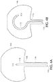
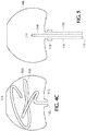
Figures 4A-4C represent enlarged partial views in sequence of the intrasaccular flow diverter illustrating the connection point or interface between the dome braid and the interior fill braid ofFigure 2A at three different stages of advancement in a distal direction of the interior fill braid through the microcatheter and into the cavity of the stationary deployed dome braid; whereinFigure 4A is an enlarged partial view of the interior fill braid of the intrasaccular flow diverter ofFigure 2A wherein the free end of the interior fill braid is beginning to emerge into the deployed dome braid;Figure 4B is an enlarged partial view of the interior fill braid extending further and partially deployed inside the deployed dome braid; whileFigure 4C is an enlarged partial view of the interior fill braid of the intrasaccular flow diverter ofFigure 3A wherein the interior fill braid extends even further and is fully deployed inside the deployed dome braid; and -
Figure 5 is an enlarged partial view of the intrasaccular flow diverter ofFigure 2A depicting a particular embodiment in which securement between the neck of the deployed dome braid and the interior fill braid at the connection point or interface is accomplished using a crimped marker band. - The terms "distal" or "proximal" are used in the following description with respect to a position or direction relative to the treating physician or medical interventionalist. "Distal" or "distally" are a position distant from or in a direction away from the physician or interventionalist. "Proximal" or "proximally" or "proximate" are a position near or in a direction toward the physician or medical interventionist. The terms "occlusion", "clot" or "blockage" are used interchangeably.
-
Figure 1A depicts the present inventive intrasaccular flow diverter 100 maneuvered through a blood vessel (BV) via a lumen of amicrocatheter 115 to a target site aligned with an aneurysm (A) to be treated. WhileFigure 1B , depicts an enlarged view of section I(B) of the intrasaccular flow diverter 100 inFigure 1A . Referring to the enlarged view inFigure 1B ,intrasaccular flow diverter 100 is composed of two parts, that is, adome braid 105 disposed distally of aninterior fill braid 110 "socked in" within itself, as described in further detail below. Both the dome braid andinterior fill braid Figures 1A & 1B . An open proximal end of thedome braid 105 is permanently, fixedly or non-releasably attached to an open distal end of theinterior fill braid 110 at a connection point orinterface 113. Various configurations are contemplated and within the intended scope of the present invention for connecting, attaching or securing thedome braid 105 to theinterior fill braid 110 at the connection point orinterface 113. InFigures 1A, 1B ,2A, 2B ,3A, 3B ,4A-4C the connection point orinterface 113 betweendome braid 105 andinterior fill braid 110 is a laser weld. Other conventional non-mechanical forms of attachment such as, but not limited to adhesive is possible. Alternatively, a mechanical device such as a band orring 500 crimped about the twobraids Figure 5 . The band or ring is preferably: (i) made of a radiopaque material; (ii) includes one or more radiopaque features; or (iii) has at least a portion thereof with a radiopaque material covering layer to aid in visibility during maneuvering of the intrasaccular flow diverter through the vasculature to the target site using conventional imaging technology. - Addressing each component separately,
dome braid 105 is a self-expanding braid, mesh, cage or skeleton with a plurality of openings defined therein. The dome braid is made of a biocompatible material for which the pattern, braid angle and number of wires comprising the braid may be selected, as desired. Upon application of an external physical mechanical force (e.g., during insertion into and advancement through the lumen of the microcatheter 115),dome braid 105 is collapsible to a compressed or contracted state having a cylindrical tube configuration sufficiently reduced in overall diameter to be receivable within the lumen of amicrocatheter 115. Absent or free of application of an external physical mechanical force (e.g., prior to the dome braid being introduced into the lumen of the microcatheter; and thereafter upon the dome braid exiting from the distal end of the microcatheter),dome braid 105 is in an expanded or non-compressed state having a "domed", spherical or hemi-spherical shape with an enlarged or maximum overall diameter. -
Interior fill braid 110 is similarly configured as a self-expanding braid, mesh, cage or skeleton with a plurality of openings defined therein. During insertion of the intrasaccularflow diverter device 100 into the lumen of the microcatheter, theinterior fill braid 110 is in a contracted or compressed state taking on a substantially linear configuration thus reduced in overall diameter to be receivable within the lumen of themicrocatheter 115. Free or absent of application of an externally applied physical mechanical force (e.g., prior to the interior fill braid being introduced in the lumen of the microcatheter; and thereafter upon the interior fill braid exiting from the distal end of the microcatheter), theinterior fill braid 105 is in a non-compressed or expanded state having a complex helical, spiral or ribbon pre-formed configuration that fills and pushes radially outward from within the deployeddome braid 105. -
Dome braid 105 is designed to have a profile stiffness greater relative to that of theinterior fill braid 110. This increased profile stiffness of the dome braid may be achieved by varying one or more of the following properties: (i) increase the thickness (diameter) of the individual wires forming the braid, mesh, cage or skeleton; (ii) decrease the braid angle; and (iii) increase the number of wires forming the braid. In contrast, the reduced profile stiffness of theinterior fill braid 110 is sufficiently flexible or pliable to allow the interior fill braid to be physically turned outside in (i.e., its outer surface turned inward like that of a sock or a sleeve). Hereinafter, the interior fill braid while in a state turned "outside in" is hereinafter generically referred to as being - inverted, retracted, drawn, flipped or socked - inward onto itself. That is, while the distal end of theinterior fill braid 110 remains permanently secured, connected or attached to the open proximal end (neck) of thedome braid 105 at the connection point orinterface 113, the oppositefree end 111 of theinterior fill braid 110 is "socked inwards" or "drawn inwards" in a distal direction through the axial passageway defined within the interior fill braid forming an invertedproximal end 112. In turn, the invertedproximal end 112 of theinterior fill braid 110 is releasably/detachably secured, attached, connected or mounted to a pusher ordelivery wire 120.Intrasaccular flow diverter 100 is advanceable in a distal direction through the lumen of themicrocatheter 115 using the pusher ordelivery wire 120. Preferably, theinterior fill braid 110 is inverted, retracted, drawn, flipped or socked onto itself in a distal direction to such extent that the free inverted end of the interior fill braid extends beyond the connection point orinterface 113 and into thedome braid 105. As a result of its increased profile stiffness deployeddome braid 105 maintains its shape while the invertedinterior fill braid 110 is advanced in a distal direction into the cavity formed by the deployeddome braid 105. - During manufacture of the intrasaccular flow diverter (in a non-compressed or expanded state not subject to application of an external physical mechanical force),
dome braid 105 is pre-formed to have a domed, spherical or hemispherical shape; whereasinterior fill braid 110 has a complex spiral, helical or any other pre-formed shape sufficient to apply physical force radially outward against the interior wall of the deployed dome braid apposing the aneurysm. - As illustrated in
Figure 1A , during treatment of the aneurysm using the present inventiveintrasaccular flow diverter 100,microcatheter 115 is initially introduced into the body, preferably via the groin, and maneuvered intravascularly through the blood vessel (BV) to a target site (e.g., substantially aligned with a target aneurysm (A) to be treated). While thedome braid 105 andinterior fill braid 110 are both in a compressed or contracted state reduced in overall diameter (as shown inFigures 1A & 1B ), the present inventiveintrasaccular flow diverter 100 is advanced in a distal direction through the lumen of themicrocatheter 115 using a pusher ordelivery wire 120. In this compressed or contractedstate dome braid 105 is collapsed whileinterior fill braid 110 is maintained in a substantially straight or linear configuration such that each component has a reduced overall diameter receivable within the lumen of the microcatheter. - As the
intrasaccular flow diverter 100 is advanced distally through themicrocatheter 115 using the pusher ordelivery wire 120,braid dome 105 is first to emerge from the distal end of themicrocatheter 115.Dome braid 105 is fully deployed when theconnection point 113 is proximate the distal end of themicrocatheter 115. No longer physically constrained by the interior walls of themicrocatheter 115,braid dome 105 automatically reverts to its pre-formed spherical or hemispherical ("dome") shape (i.e., returning to its non-compressed state) having an enlarged or expanded overall diameter filling the aneurysm to be treated, as shown inFigure 2A . Also visible in the illustration inFigure 2A is that portion of thefree end 111 of theinterior fill braid 110 that extends in a distal direction beyond the connection point orinterface 113 and into the cavity of the deployeddome braid 105. At this stage of treatment, since only a relatively small portion of theinverted fill braid 110 extends into the cavity of the deployeddome braid 105, despite not being constrained by themicrocatheter 115, that exposed portion of the interior fill braid nevertheless remains substantially linear or straight. - As previously mentioned, since the
dome braid 105 has a stiffer profile relative to that of theinterior fill braid 110, the deployeddome braid 105 remains stationary in the aneurysm to be treated as theinterior fill braid 110 is pushed or advanced further in a distal direction through the neck and into the cavity of thedome braid 105 using the pusher ordelivery wire 120. With the continued advancement of the intrasaccular flow diverter in a distal direction, the increasing portion of theinterior fill braid 110 that is no longer constrained by the microcatheter automatically reverts back to its complex helical or spiral pre-formed shape, as depicted inFigure 4B . - In
Figure 3A , theinterior fill braid 110 is still further advanced in a distal direction by the interventionalist using the pusher ordelivery wire 120 through the neck and interiorly into the cavity of the expandeddome braid 105. Advancement of theinterior fill braid 110 ceases when the invertedproximal end 112 of theinterior fill braid 110 is exterior of and proximate the proximal opening (neck) of the deployeddome braid 105. At that point, the pusher ordelivery wire 120 is released or detached from the proximalinverted end 112 ofinterior fill braid 110, whereupon the pusher ordelivery wire 120 is withdrawn in a proximal direction through themicrocatheter 115 from the body.Figure 3B is an enlarged section III(B) inFigure 3A of the invertedproximal end 112 of theinterior fill braid 110 released from the pusher ordelivery wire 120. Within the deployeddome braid 105 the detachedinterior fill braid 110 automatically deploys returning to its non-inverted (pre-shaped) state (e.g., a complex spiral shape, helical shape or any other desirable shape) applying a radially outward force on the interior wall of the deployed dome braid apposing the aneurysm, as depicted inFigure 3A . Even when theinterior fill braid 110 is fully deployed and free from the pusher ordelivery wire 120 the invertedproximal end 112 of theinterior fill braid 110 remains exterior of the deployeddome braid 105. Releasement or detachment of the pusher ordelivery wire 120 from the proximalinverted end 112 of theinterior fill braid 110 may be accomplished in any number of conventional ways. For example, release may occur automatically when a simple pusher or delivery wire exits from the distal end of the microcatheter. Alternative electrical, mechanical or hydraulic detachment processes or mechanisms are contemplated to achieve deployment. - The inverted interior fill braid of the present inventive intrasaccular flow diverter has been described above as being sufficiently flexible or pliable to permit the interior fill braid to be physically turned "outside in" (i.e., its outer surface turned inward like that of a sock or a sleeve). Such is the case where the distal end of the non-inverted interior fill braid is first connected, secured or attached to the proximal opening (neck) of the
dome braid 105 at the connection point orinterface 113 before the interior fill braid is inverted, retracted, socked or drawn onto itself. However, if the interior fill braid is initially inverted, retracted, socked or drawn onto itself prior to being connected to the proximal opening (neck) of thedome braid 105, it is contemplated that the interior fill braid may be inverted, retracted, socked or drawn onto itself either: by turning the "outside in", i.e., drawing thefree end 111 inwards in a distal direction through the axial passageway defined within the interior fill braid forming the invertedproximal end 112; or turning the "inside out", i.e., drawing thefree end 111 outwards in a distal direction over the outside of the interior fill braid forming the invertedproximal end 112. Regardless of the process followed to produce the inverted interior fill braid (irrespective of whether the interior braid is turned "outside in" or "inside out") the resulting structure is the same. That is, the inverted interior fill braid is non-releasably secured to the neck of the dome braid at theconnection point 113, has afree end 111 disposed inside the cavity of thedome braid 105, and an invertedproximal end 112. Thus, to encompass either process the term "inverted" is generically defined as drawn back over itself, encompassing both "drawn inward"/"outside in" or "drawn outward"/inside out". - The present inventive intrasaccular flow diverter provides numerous advantages some of which are summarized herein. On the one hand, the expanded
dome braid 105 retains interiorly therein the deployedinterior fill braid 110 restricting shifting or movement of the interior fill braid, while simultaneously the deployedinterior fill braid 110 apposing the aneurysm results in the deployed dome braid substantially conforming in shape to that of the aneurysm. Accordingly, the present inventive intrasaccular flow diverter may universally be used for treatment of a wide variety of shape and size aneurysms with improved adequacy of occlusion. In addition, the neck of the deployed dome braid seals the aneurysm. The multicomponent structure of the present inventive intrasaccular flow diverter both fills the aneurysm with the deployed dome braid while simultaneously occluding the aneurysm with the deployed interior fill braid exerting force radially outward from within. Moreover, the present inventive intrasaccular flow diverter fills and occludes the aneurysm using a single device, which heretofore required packing of a plurality (e.g., 5-10) of coils requiring more time during treatment and risk of shifting. - Thus, while there have been shown, described, and pointed out fundamental novel features of the invention as applied to a preferred embodiment thereof, it will be understood that various omissions, substitutions, and changes in the form and details of the systems/devices illustrated, and in their operation, may be made by those skilled in the art without departing from the spirit and scope of the invention. For example, it is expressly intended that all combinations of those elements and/or steps that perform substantially the same function, in substantially the same way, to achieve the same results be within the scope of the invention. Substitutions of elements from one described embodiment to another are also fully intended and contemplated. It is also to be understood that the drawings are not necessarily drawn to scale, but that they are merely conceptual in nature. It is the intention, therefore, to be limited only as indicated by the scope of the claims appended hereto.
- Every issued patent, pending patent application, publication, journal article, book or any other reference cited herein is each incorporated by reference in their entirety.
Claims (15)
- An intrasaccular flow diverter comprising:
an interior fill braid physically inverted over itself forming a proximal inverted end and an opposite free end:a dome braid disposed distally of and secured to the interior fill braid; subject to application of an external mechanical force, the dome braid being transitionable between an expanded state and a compressed state having a reduced overall diameter; the dome braid having a proximal end with an opening defined therein through which the free end of the interior fill braid is freely passable therethrough and into the dome braid; anda delivery wire releasably detachable from the proximal inverted end of the interior fill braid;wherein the dome braid has a stiffer profile relative to that of the interior fill braid. - The intrasaccular flow diverter according to claim 1, wherein: (i) the interior fill braid has a complex spiral or helical pre-formed shape in the expanded state; and a substantially linear configuration in the compressed state; and (ii) the dome braid has a domed, spherical or hemi-spherical pre-formed shape in the expanded state; and a cylindrical tube configuration in the compressed state.
- The intrasaccular flow diverter according to any preceding claim, wherein the dome braid and interior fill braid are secured together proximate the opening by a band marker.
- The intrasaccular flow diverter according to any preceding claim, wherein the stiffer profile of the dome braid relative to that of the interior fill braid is achievable by at least one of the following characteristics: (i) increase thickness of individual wires forming the dome braid; (ii) decrease braid angle between wire forming the dome braid; and (iii) increase number of wires forming the dome braid.
- A method for treatment of an aneurysm using an intrasaccular flow diverter, wherein the intrasaccular flow diverter includes an interior fill braid physically invertible over itself forming a proximal inverted end and an opposite free end; a dome braid disposed distally of the interior fill braid; the dome braid being transitionable subject to application of an external mechanical force from an expanded state to a compressed state having a reduced overall diameter; the dome braid having a proximal end with an opening defined therein through which the free end of the interior fill braid is freely passable therethrough and into the dome braid; and a delivery wire releasably detachable from the proximal inverted end of the interior fill braid; wherein the dome braid has a stiffer profile relative to that of the interior fill braid; the method comprising the steps of:navigating a microcatheter through a vessel to a target site proximate the aneurysm;using the delivery wire, advancing through a lumen of the microcatheter the intrasaccular flow diverter while the dome braid and interior fill braid are each in the compressed state;upon exiting from a distal end of the microcatheter, automatically deploying the dome braid to the expanded state having an enlarged diameter filling the aneurysm, wherein only a distal portion of the interior fill braid including the free end is disposed interiorly of the deployed dome braid;while the deployed dome braid is maintained filling in the aneurysm, using the delivery wire further advancing through the lumen of the microcatheter the intrasaccular flow diverter until the inverted proximal end of the interior fill braid is positioned proximate to, but remains exterior of, the deployed dome braid; andreleasing the delivery wire from the inverted proximal end of the interior fill braid allowing the interior fill braid to automatically transition to the expanded state interiorly exerting a force radially outward against the deployed dome braid to substantially conform in shape with that of the aneurysm.
- The method according to claim 5, wherein: (i) the interior fill braid has a complex spiral or helical pre-formed shape in the expanded state; and a substantially linear configuration in the compressed state; and (ii) the dome braid has a domed, spherical or hemi-spherical pre-formed shape in the expanded state; and a cylindrical tube configuration in the compressed state.
- The method according to claim 5 or claim 6, wherein the dome braid and interior fill braid are secured together proximate the opening by a band marker.
- The method according to any of claims 5 to 7, wherein the stiffer profile of the dome braid relative to that of the interior fill braid is achieved by at least one of the following characteristics: (i) increase thickness of individual wires forming the dome braid; (ii) decrease braid angle between wire forming the dome braid; and (iii) increase number of wires forming the dome braid.
- A method for treatment of an aneurysm using an intrasaccular flow diverter, wherein the intrasaccular flow diverter includes an interior fill braid and a dome braid disposed distally of the interior fill braid; the method comprising the steps of:deploying the dome braid within the aneurysm to be treated; wherein the deployed dome braid reverts to a dome, sphere or hemispherical pre-formed shape; andapposing so as to conform in shape the deployed dome braid to that of the aneurysm to be treated by imparting interiorly on the deployed dome braid a radially outward force using the interior fill braid introduced therein.
- The method according to claim 9, wherein the interior fill braid is physically invertible over itself forming a proximal inverted end and an opposite free end; the dome braid is transitionable subject to application of an external mechanical force from an expanded state to a compressed state having a reduced overall diameter; the dome braid has a proximal end with an opening defined therein through which the free end of the interior fill braid is freely passable therethrough and into the dome braid.
- The method according to claim 9 or claim 10, wherein the intrasaccular flow diverter further comprises a delivery wire releasably detachable from the proximal inverted end of the interior fill braid.
- The method according to any of claims 9 to 11, wherein the dome braid has a stiffer profile relative to that of the interior fill braid.
- The method according to any of claims 9 to 12, wherein: (i) the interior fill braid has a complex spiral or helical pre-formed shape in the expanded state; and a substantially linear configuration in the compressed state; and (ii) the dome braid has a domed, spherical or hemi-spherical pre-formed shape in the expanded state; and a cylindrical tube configuration in the compressed state.
- The method according to any of claims 9 to 13, wherein the dome braid and interior fill braid are secured together proximate the opening by a band marker.
- The method according to any of claims 12 to 14, wherein the stiffer profile of the dome braid relative to that of the interior fill braid is achieved by at least one of the following characteristics: (i) increase thickness of individual wires forming the dome braid; (ii) decrease braid angle between wire forming the dome braid; and (iii) increase number of wires forming the dome braid.
Applications Claiming Priority (1)
| Application Number | Priority Date | Filing Date | Title |
|---|---|---|---|
| US16/863,334 US11523831B2 (en) | 2020-04-30 | 2020-04-30 | Intrasaccular flow diverter |
Publications (1)
| Publication Number | Publication Date |
|---|---|
| EP3903695A1 true EP3903695A1 (en) | 2021-11-03 |
Family
ID=75746351
Family Applications (1)
| Application Number | Title | Priority Date | Filing Date |
|---|---|---|---|
| EP21171361.5A Withdrawn EP3903695A1 (en) | 2020-04-30 | 2021-04-29 | Intrasaccular flow diverter |
Country Status (5)
| Country | Link |
|---|---|
| US (2) | US11523831B2 (en) |
| EP (1) | EP3903695A1 (en) |
| JP (1) | JP7663176B2 (en) |
| KR (1) | KR20210134223A (en) |
| CN (1) | CN113576576A (en) |
Families Citing this family (1)
| Publication number | Priority date | Publication date | Assignee | Title |
|---|---|---|---|---|
| US12004750B2 (en) | 2008-05-01 | 2024-06-11 | Aneuclose Llc | Methods for creating an expandable two-part intrasacular aneurysm occlusion device from a tubular mesh |
Citations (3)
| Publication number | Priority date | Publication date | Assignee | Title |
|---|---|---|---|---|
| US20180242979A1 (en) * | 2017-02-23 | 2018-08-30 | DePuy Synthes Products, Inc. | Aneurysm device and delivery system |
| EP3607895A2 (en) * | 2018-08-08 | 2020-02-12 | DePuy Synthes Products, Inc. | Delivery system for embolic braid |
| US20200069313A1 (en) * | 2018-05-25 | 2020-03-05 | DePuy Synthes Products, Inc. | Aneurysm device and delivery system |
Family Cites Families (111)
| Publication number | Priority date | Publication date | Assignee | Title |
|---|---|---|---|---|
| GB9715241D0 (en) * | 1997-07-18 | 1997-09-24 | Jeffree Martin A | Device for treating aneurysms |
| US6346117B1 (en) * | 2000-03-02 | 2002-02-12 | Prodesco, Inc. | Bag for use in the intravascular treatment of saccular aneurysms |
| US8252040B2 (en) | 2001-07-20 | 2012-08-28 | Microvention, Inc. | Aneurysm treatment device and method of use |
| US8715312B2 (en) | 2001-07-20 | 2014-05-06 | Microvention, Inc. | Aneurysm treatment device and method of use |
| US7371228B2 (en) | 2003-09-19 | 2008-05-13 | Medtronic Vascular, Inc. | Delivery of therapeutics to treat aneurysms |
| US9308382B2 (en) | 2004-06-10 | 2016-04-12 | Medtronic Urinary Solutions, Inc. | Implantable pulse generator systems and methods for providing functional and/or therapeutic stimulation of muscles and/or nerves and/or central nervous system tissue |
| US9655633B2 (en) | 2004-09-10 | 2017-05-23 | Penumbra, Inc. | System and method for treating ischemic stroke |
| US20060089637A1 (en) | 2004-10-14 | 2006-04-27 | Werneth Randell L | Ablation catheter |
| US8562672B2 (en) | 2004-11-19 | 2013-10-22 | Medtronic, Inc. | Apparatus for treatment of cardiac valves and method of its manufacture |
| US9636115B2 (en) | 2005-06-14 | 2017-05-02 | Stryker Corporation | Vaso-occlusive delivery device with kink resistant, flexible distal end |
| EP1895927A4 (en) | 2005-06-20 | 2011-03-09 | Medtronic Ablation Frontiers | Ablation catheter |
| US8066036B2 (en) | 2005-11-17 | 2011-11-29 | Microvention, Inc. | Three-dimensional complex coil |
| US9757260B2 (en) | 2006-03-30 | 2017-09-12 | Medtronic Vascular, Inc. | Prosthesis with guide lumen |
| US9615832B2 (en) | 2006-04-07 | 2017-04-11 | Penumbra, Inc. | Aneurysm occlusion system and method |
| CA2655026C (en) | 2006-06-15 | 2016-08-02 | Microvention, Inc. | Embolization device constructed from expansible polymer |
| WO2009086208A2 (en) | 2007-12-21 | 2009-07-09 | Microvention, Inc. | Hydrogel filaments for biomedical uses |
| US8974518B2 (en) | 2008-03-25 | 2015-03-10 | Medtronic Vascular, Inc. | Eversible branch stent-graft and deployment method |
| WO2009135075A1 (en) | 2008-04-30 | 2009-11-05 | Medtronic, Inc. | Techniques for placing medical leads for electrical stimulation of nerve tissue |
| US8070694B2 (en) | 2008-07-14 | 2011-12-06 | Medtronic Vascular, Inc. | Fiber based medical devices and aspiration catheters |
| US8333796B2 (en) | 2008-07-15 | 2012-12-18 | Penumbra, Inc. | Embolic coil implant system and implantation method |
| US8721714B2 (en) | 2008-09-17 | 2014-05-13 | Medtronic Corevalve Llc | Delivery system for deployment of medical devices |
| JP5608731B2 (en) | 2009-04-15 | 2014-10-15 | マイクロベンション インコーポレイテッド | Implant delivery system |
| WO2011038017A1 (en) | 2009-09-22 | 2011-03-31 | Penumbra, Inc. | Manual actuation system for deployment of implant |
| CA2795740C (en) | 2010-04-14 | 2018-03-13 | Microvention, Inc. | Implant delivery device |
| US8764811B2 (en) | 2010-04-20 | 2014-07-01 | Medtronic Vascular, Inc. | Controlled tip release stent graft delivery system and method |
| US8876878B2 (en) | 2010-07-23 | 2014-11-04 | Medtronic, Inc. | Attachment mechanism for stent release |
| US8616040B2 (en) | 2010-09-17 | 2013-12-31 | Medtronic Vascular, Inc. | Method of forming a drug-eluting medical device |
| WO2012088162A1 (en) | 2010-12-20 | 2012-06-28 | Microvention, Inc. | Polymer stents and methods of manufacture |
| US9486604B2 (en) | 2011-05-12 | 2016-11-08 | Medtronic, Inc. | Packaging and preparation tray for a delivery system |
| WO2012158668A1 (en) | 2011-05-17 | 2012-11-22 | Stryker Corporation | Method of fabricating an implantable medical device that includes one or more thin film polymer support layers |
| WO2012166467A1 (en) | 2011-05-27 | 2012-12-06 | Stryker Corporation | Assembly for percutaneously inserting an implantable medical device, steering the device to a target location and deploying the device |
| US9750565B2 (en) | 2011-09-30 | 2017-09-05 | Medtronic Advanced Energy Llc | Electrosurgical balloons |
| CA2867181C (en) | 2012-03-16 | 2020-08-11 | Microvention, Inc. | Stent and stent delivery device |
| US9717421B2 (en) | 2012-03-26 | 2017-08-01 | Medtronic, Inc. | Implantable medical device delivery catheter with tether |
| US9833625B2 (en) | 2012-03-26 | 2017-12-05 | Medtronic, Inc. | Implantable medical device delivery with inner and outer sheaths |
| US9242290B2 (en) | 2012-04-03 | 2016-01-26 | Medtronic Vascular, Inc. | Method and apparatus for creating formed elements used to make wound stents |
| US9549832B2 (en) | 2012-04-26 | 2017-01-24 | Medtronic Vascular, Inc. | Apparatus and methods for filling a drug eluting medical device via capillary action |
| US9700399B2 (en) | 2012-04-26 | 2017-07-11 | Medtronic Vascular, Inc. | Stopper to prevent graft material slippage in a closed web stent-graft |
| US9149190B2 (en) | 2012-07-17 | 2015-10-06 | Stryker Corporation | Notification system of deviation from predefined conditions |
| US9770251B2 (en) | 2012-08-13 | 2017-09-26 | Microvention, Inc. | Shaped removal device |
| US9504476B2 (en) | 2012-10-01 | 2016-11-29 | Microvention, Inc. | Catheter markers |
| BR112015008245B1 (en) | 2012-10-15 | 2022-09-27 | Microvention, Inc | POLYMERIC TREATMENT COMPOSITIONS |
| US9539022B2 (en) | 2012-11-28 | 2017-01-10 | Microvention, Inc. | Matter conveyance system |
| WO2014089392A1 (en) | 2012-12-07 | 2014-06-12 | Medtronic, Inc. | Minimally invasive implantable neurostimulation system |
| US9539382B2 (en) | 2013-03-12 | 2017-01-10 | Medtronic, Inc. | Stepped catheters with flow restrictors and infusion systems using the same |
| EP2967572B1 (en) | 2013-03-14 | 2019-04-24 | Stryker Corporation | Vaso-occlusive device delivery system |
| EP3009084B1 (en) | 2013-03-14 | 2017-09-13 | Stryker Corporation | Vaso-occlusive device delivery system |
| US9539011B2 (en) | 2013-03-14 | 2017-01-10 | Stryker Corporation | Vaso-occlusive device delivery system |
| US9398966B2 (en) | 2013-03-15 | 2016-07-26 | Medtronic Vascular, Inc. | Welded stent and stent delivery system |
| JP6636908B2 (en) | 2013-03-15 | 2020-01-29 | テルモ株式会社 | Embolism prevention device |
| US9833252B2 (en) | 2013-03-15 | 2017-12-05 | Microvention, Inc. | Multi-component obstruction removal system and method |
| WO2014174437A1 (en) | 2013-04-22 | 2014-10-30 | Sandvik Intellectual Property Ab | Method for drug loading hydroxyapatite coated implant surfaces |
| US9445928B2 (en) | 2013-05-30 | 2016-09-20 | Medtronic Vascular, Inc. | Delivery system having a single handed deployment handle for a retractable outer sheath |
| US9675782B2 (en) | 2013-10-10 | 2017-06-13 | Medtronic Vascular, Inc. | Catheter pull wire actuation mechanism |
| US9955978B2 (en) | 2013-10-25 | 2018-05-01 | Medtronic Vascular, Inc. | Tissue compression device with multi-chamber bladder |
| CA2934555C (en) | 2013-12-20 | 2020-07-07 | Microvention, Inc. | Device delivery system |
| US9833604B2 (en) | 2013-12-20 | 2017-12-05 | Microvention, Inc. | Delivery adapter |
| EP3128962B1 (en) | 2014-04-08 | 2018-05-23 | Stryker Corporation | Implant delivery system |
| WO2015167997A1 (en) | 2014-04-30 | 2015-11-05 | Stryker Corporation | Implant delivery system and method of use |
| US9060777B1 (en) | 2014-05-28 | 2015-06-23 | Tw Medical Technologies, Llc | Vaso-occlusive devices and methods of use |
| US9668898B2 (en) | 2014-07-24 | 2017-06-06 | Medtronic Vascular, Inc. | Stent delivery system having dynamic deployment and methods of manufacturing same |
| US9770577B2 (en) | 2014-09-15 | 2017-09-26 | Medtronic Xomed, Inc. | Pressure relief for a catheter balloon device |
| US9579484B2 (en) | 2014-09-19 | 2017-02-28 | Medtronic Vascular, Inc. | Sterile molded dispenser |
| US9692557B2 (en) | 2015-02-04 | 2017-06-27 | Stryker European Holdings I, Llc | Apparatus and methods for administering treatment within a bodily duct of a patient |
| US10307168B2 (en) | 2015-08-07 | 2019-06-04 | Terumo Corporation | Complex coil and manufacturing techniques |
| US10154905B2 (en) | 2015-08-07 | 2018-12-18 | Medtronic Vascular, Inc. | System and method for deflecting a delivery catheter |
| EP3334354B1 (en) | 2015-08-11 | 2021-03-03 | Terumo Corporation | System for implant delivery |
| JP6816126B2 (en) | 2015-09-18 | 2021-01-20 | マイクロベンション インコーポレイテッドMicrovention, Inc. | Releasable delivery system |
| EP3349689B1 (en) | 2015-09-18 | 2023-12-27 | Microvention, Inc. | Implant retention, detachment, and delivery system |
| CN108156803B (en) | 2015-09-18 | 2021-05-04 | 泰尔茂株式会社 | Pushable Implant Delivery System |
| JP6816127B2 (en) | 2015-09-18 | 2021-01-20 | テルモ株式会社 | Vascular prosthesis |
| CN108024821B (en) | 2015-09-21 | 2020-10-30 | 斯瑞克公司 | embolectomy device |
| ES2788738T3 (en) | 2015-09-21 | 2020-10-22 | Stryker Corp | Embolectomy devices |
| US10172632B2 (en) | 2015-09-22 | 2019-01-08 | Medtronic Vascular, Inc. | Occlusion bypassing apparatus with a re-entry needle and a stabilization tube |
| WO2017062383A1 (en) | 2015-10-07 | 2017-04-13 | Stryker Corporation | Multiple barrel clot removal devices |
| US10327791B2 (en) | 2015-10-07 | 2019-06-25 | Medtronic Vascular, Inc. | Occlusion bypassing apparatus with a re-entry needle and a distal stabilization balloon |
| US10786302B2 (en) | 2015-10-09 | 2020-09-29 | Medtronic, Inc. | Method for closure and ablation of atrial appendage |
| US10271873B2 (en) | 2015-10-26 | 2019-04-30 | Medtronic Vascular, Inc. | Sheathless guide catheter assembly |
| US20170147765A1 (en) | 2015-11-19 | 2017-05-25 | Penumbra, Inc. | Systems and methods for treatment of stroke |
| US10631946B2 (en) | 2015-11-30 | 2020-04-28 | Penumbra, Inc. | System for endoscopic intracranial procedures |
| WO2017100472A1 (en) | 2015-12-09 | 2017-06-15 | Medtronic Vascular Inc. | Catheter with a lumen shaped as an identification symbol |
| US10500046B2 (en) | 2015-12-14 | 2019-12-10 | Medtronic, Inc. | Delivery system having retractable wires as a coupling mechanism and a deployment mechanism for a self-expanding prosthesis |
| US10159568B2 (en) | 2015-12-14 | 2018-12-25 | Medtronic, Inc. | Delivery system having retractable wires as a coupling mechanism and a deployment mechanism for a self-expanding prosthesis |
| US10743883B2 (en) | 2015-12-30 | 2020-08-18 | Stryker European Holdings I, Llc | Embolic devices and methods of manufacturing same |
| US20170189033A1 (en) | 2016-01-06 | 2017-07-06 | Microvention, Inc. | Occlusive Embolic Coil |
| US10070950B2 (en) | 2016-02-09 | 2018-09-11 | Medtronic Vascular, Inc. | Endoluminal prosthetic assemblies, and associated systems and methods for percutaneous repair of a vascular tissue defect |
| AU2017217879B9 (en) | 2016-02-10 | 2021-08-19 | Microvention, Inc. | Intravascular treatment site access |
| AU2017218115B2 (en) | 2016-02-10 | 2020-03-05 | Microvention, Inc. | Devices for vascular occlusion |
| US10188500B2 (en) | 2016-02-12 | 2019-01-29 | Medtronic Vascular, Inc. | Stent graft with external scaffolding and method |
| EP4112111A1 (en) | 2016-03-31 | 2023-01-04 | Medtronic Vascular Inc. | Expandable introducer sheath |
| US20170281331A1 (en) | 2016-03-31 | 2017-10-05 | Medtronic Vascular, Inc. | Endoluminal prosthetic devices having fluid-absorbable compositions for repair of a vascular tissue defect |
| US10695542B2 (en) | 2016-04-04 | 2020-06-30 | Medtronic Vascular, Inc. | Drug coated balloon |
| US10252024B2 (en) | 2016-04-05 | 2019-04-09 | Stryker Corporation | Medical devices and methods of manufacturing same |
| US10441407B2 (en) | 2016-04-12 | 2019-10-15 | Medtronic Vascular, Inc. | Gutter filling stent-graft and method |
| US9987122B2 (en) | 2016-04-13 | 2018-06-05 | Medtronic Vascular, Inc. | Iliac branch device and method |
| US10010403B2 (en) | 2016-04-18 | 2018-07-03 | Medtronic Vascular, Inc. | Stent-graft prosthesis and method of manufacture |
| US20170304097A1 (en) | 2016-04-21 | 2017-10-26 | Medtronic Vascular, Inc. | Stent-graft delivery system having an inner shaft component with a loading pad or covering on a distal segment thereof for stent retention |
| JP6924256B2 (en) | 2016-04-25 | 2021-08-25 | ストライカー コーポレイションStryker Corporation | Pre-installed reversing tractor thrombectomy device and method |
| US10517711B2 (en) | 2016-04-25 | 2019-12-31 | Medtronic Vascular, Inc. | Dissection prosthesis system and method |
| ES2859656T3 (en) | 2016-04-25 | 2021-10-04 | Stryker Corp | Anti-jam and macerant thrombectomy appliances |
| JP6934935B2 (en) | 2016-04-25 | 2021-09-15 | ストライカー コーポレイションStryker Corporation | Inverted mechanical thrombectomy and intravascular use |
| US10940294B2 (en) | 2016-04-25 | 2021-03-09 | Medtronic Vascular, Inc. | Balloon catheter including a drug delivery sheath |
| US11147952B2 (en) | 2016-04-28 | 2021-10-19 | Medtronic Vascular, Inc. | Drug coated inflatable balloon having a thermal dependent release layer |
| US10406011B2 (en) | 2016-04-28 | 2019-09-10 | Medtronic Vascular, Inc. | Implantable medical device delivery system |
| US10191615B2 (en) | 2016-04-28 | 2019-01-29 | Medtronic Navigation, Inc. | Method and apparatus for image-based navigation |
| US10292844B2 (en) | 2016-05-17 | 2019-05-21 | Medtronic Vascular, Inc. | Method for compressing a stented prosthesis |
| CN113648518B (en) | 2016-06-01 | 2023-10-20 | 微仙美国有限公司 | Improved reinforced balloon catheter |
| JP6980703B2 (en) | 2016-06-03 | 2021-12-15 | ストライカー コーポレイションStryker Corporation | Inverting thrombectomy device |
| WO2018044941A1 (en) * | 2016-09-01 | 2018-03-08 | Microvention, Inc. | Temporary aortic occlusion device |
| US10905430B2 (en) * | 2018-01-24 | 2021-02-02 | DePuy Synthes Products, Inc. | Aneurysm device and delivery system |
| US11129621B2 (en) * | 2018-12-17 | 2021-09-28 | Covidien Lp | Devices, systems, and methods for the treatment of vascular defects |
-
2020
- 2020-04-30 US US16/863,334 patent/US11523831B2/en active Active
-
2021
- 2021-04-12 KR KR1020210046918A patent/KR20210134223A/en not_active Withdrawn
- 2021-04-26 JP JP2021073848A patent/JP7663176B2/en active Active
- 2021-04-29 EP EP21171361.5A patent/EP3903695A1/en not_active Withdrawn
- 2021-04-30 CN CN202110481789.7A patent/CN113576576A/en not_active Withdrawn
-
2022
- 2022-11-10 US US18/054,311 patent/US20230074470A1/en not_active Abandoned
Patent Citations (3)
| Publication number | Priority date | Publication date | Assignee | Title |
|---|---|---|---|---|
| US20180242979A1 (en) * | 2017-02-23 | 2018-08-30 | DePuy Synthes Products, Inc. | Aneurysm device and delivery system |
| US20200069313A1 (en) * | 2018-05-25 | 2020-03-05 | DePuy Synthes Products, Inc. | Aneurysm device and delivery system |
| EP3607895A2 (en) * | 2018-08-08 | 2020-02-12 | DePuy Synthes Products, Inc. | Delivery system for embolic braid |
Also Published As
| Publication number | Publication date |
|---|---|
| US11523831B2 (en) | 2022-12-13 |
| KR20210134223A (en) | 2021-11-09 |
| US20230074470A1 (en) | 2023-03-09 |
| JP2021171654A (en) | 2021-11-01 |
| JP7663176B2 (en) | 2025-04-16 |
| CN113576576A (en) | 2021-11-02 |
| US20210338250A1 (en) | 2021-11-04 |
Similar Documents
| Publication | Publication Date | Title |
|---|---|---|
| US20220378435A1 (en) | Filamentary devices having a flexible joint for treatment of vascular defects | |
| EP3908209B1 (en) | Filamentary devices for treatment of vascular defects | |
| US11376012B2 (en) | Devices, systems, and methods for treatment of vascular defects | |
| US20220249098A1 (en) | Filamentary devices for treatment of vascular defects | |
| AU2007268135B2 (en) | Flexible vascular occluding device | |
| US7569066B2 (en) | Methods and devices for the treatment of aneurysms | |
| US20190223881A1 (en) | Devices for therapeutic vascular procedures | |
| US7695488B2 (en) | Expandable body cavity liner device | |
| EP1750619B1 (en) | Flexible vascular occluding device | |
| EP2004101A2 (en) | Aneurysm occlusion system and method | |
| EP3773251A1 (en) | Embolization scaffold devices | |
| CN117860330A (en) | Vascular occlusion device and method of manufacturing the same | |
| US20230074470A1 (en) | Intrasaccular Flow Diverter | |
| US12303413B2 (en) | Orientable implantable device and method | |
| US12161344B2 (en) | Expandable devices for treating body lumens | |
| US20230225735A1 (en) | Expandable devices for treating body lumens | |
| KR20230146275A (en) | Blood flow restricting device with multi-layer structures and composite materials | |
| WO2024046551A1 (en) | Avp device with lobe/segment designed to fill aneurysm sac |
Legal Events
| Date | Code | Title | Description |
|---|---|---|---|
| PUAI | Public reference made under article 153(3) epc to a published international application that has entered the european phase |
Free format text: ORIGINAL CODE: 0009012 |
|
| STAA | Information on the status of an ep patent application or granted ep patent |
Free format text: STATUS: THE APPLICATION HAS BEEN PUBLISHED |
|
| AK | Designated contracting states |
Kind code of ref document: A1 Designated state(s): AL AT BE BG CH CY CZ DE DK EE ES FI FR GB GR HR HU IE IS IT LI LT LU LV MC MK MT NL NO PL PT RO RS SE SI SK SM TR |
|
| B565 | Issuance of search results under rule 164(2) epc |
Effective date: 20210825 |
|
| STAA | Information on the status of an ep patent application or granted ep patent |
Free format text: STATUS: REQUEST FOR EXAMINATION WAS MADE |
|
| 17P | Request for examination filed |
Effective date: 20211117 |
|
| RBV | Designated contracting states (corrected) |
Designated state(s): AL AT BE BG CH CY CZ DE DK EE ES FI FR GB GR HR HU IE IS IT LI LT LU LV MC MK MT NL NO PL PT RO RS SE SI SK SM TR |
|
| STAA | Information on the status of an ep patent application or granted ep patent |
Free format text: STATUS: EXAMINATION IS IN PROGRESS |
|
| 17Q | First examination report despatched |
Effective date: 20221021 |
|
| GRAP | Despatch of communication of intention to grant a patent |
Free format text: ORIGINAL CODE: EPIDOSNIGR1 |
|
| STAA | Information on the status of an ep patent application or granted ep patent |
Free format text: STATUS: GRANT OF PATENT IS INTENDED |
|
| INTG | Intention to grant announced |
Effective date: 20230926 |
|
| RIN1 | Information on inventor provided before grant (corrected) |
Inventor name: LORENZO, JUAN Inventor name: SOTO DEL VALLE, ARIEL Inventor name: GOROCHOW, LACEY |
|
| STAA | Information on the status of an ep patent application or granted ep patent |
Free format text: STATUS: THE APPLICATION IS DEEMED TO BE WITHDRAWN |
|
| 18D | Application deemed to be withdrawn |
Effective date: 20240207 |