EP3903552A1 - Work vehicle - Google Patents
Work vehicle Download PDFInfo
- Publication number
- EP3903552A1 EP3903552A1 EP19902301.1A EP19902301A EP3903552A1 EP 3903552 A1 EP3903552 A1 EP 3903552A1 EP 19902301 A EP19902301 A EP 19902301A EP 3903552 A1 EP3903552 A1 EP 3903552A1
- Authority
- EP
- European Patent Office
- Prior art keywords
- illuminating
- traveling
- image
- traveling body
- lamps
- Prior art date
- Legal status (The legal status is an assumption and is not a legal conclusion. Google has not performed a legal analysis and makes no representation as to the accuracy of the status listed.)
- Granted
Links
Images









Classifications
-
- H—ELECTRICITY
- H04—ELECTRIC COMMUNICATION TECHNIQUE
- H04N—PICTORIAL COMMUNICATION, e.g. TELEVISION
- H04N7/00—Television systems
- H04N7/18—Closed-circuit television [CCTV] systems, i.e. systems in which the video signal is not broadcast
- H04N7/181—Closed-circuit television [CCTV] systems, i.e. systems in which the video signal is not broadcast for receiving images from a plurality of remote sources
-
- A—HUMAN NECESSITIES
- A01—AGRICULTURE; FORESTRY; ANIMAL HUSBANDRY; HUNTING; TRAPPING; FISHING
- A01B—SOIL WORKING IN AGRICULTURE OR FORESTRY; PARTS, DETAILS, OR ACCESSORIES OF AGRICULTURAL MACHINES OR IMPLEMENTS, IN GENERAL
- A01B69/00—Steering of agricultural machines or implements; Guiding agricultural machines or implements on a desired track
- A01B69/001—Steering by means of optical assistance, e.g. television cameras
-
- B—PERFORMING OPERATIONS; TRANSPORTING
- B60—VEHICLES IN GENERAL
- B60Q—ARRANGEMENT OF SIGNALLING OR LIGHTING DEVICES, THE MOUNTING OR SUPPORTING THEREOF OR CIRCUITS THEREFOR, FOR VEHICLES IN GENERAL
- B60Q1/00—Arrangement of optical signalling or lighting devices, the mounting or supporting thereof or circuits therefor
- B60Q1/0017—Devices integrating an element dedicated to another function
- B60Q1/0023—Devices integrating an element dedicated to another function the element being a sensor, e.g. distance sensor, camera
-
- B—PERFORMING OPERATIONS; TRANSPORTING
- B60—VEHICLES IN GENERAL
- B60Q—ARRANGEMENT OF SIGNALLING OR LIGHTING DEVICES, THE MOUNTING OR SUPPORTING THEREOF OR CIRCUITS THEREFOR, FOR VEHICLES IN GENERAL
- B60Q1/00—Arrangement of optical signalling or lighting devices, the mounting or supporting thereof or circuits therefor
- B60Q1/02—Arrangement of optical signalling or lighting devices, the mounting or supporting thereof or circuits therefor the devices being primarily intended to illuminate the way ahead or to illuminate other areas of way or environments
- B60Q1/04—Arrangement of optical signalling or lighting devices, the mounting or supporting thereof or circuits therefor the devices being primarily intended to illuminate the way ahead or to illuminate other areas of way or environments the devices being headlights
- B60Q1/06—Arrangement of optical signalling or lighting devices, the mounting or supporting thereof or circuits therefor the devices being primarily intended to illuminate the way ahead or to illuminate other areas of way or environments the devices being headlights adjustable, e.g. remotely-controlled from inside vehicle
- B60Q1/08—Arrangement of optical signalling or lighting devices, the mounting or supporting thereof or circuits therefor the devices being primarily intended to illuminate the way ahead or to illuminate other areas of way or environments the devices being headlights adjustable, e.g. remotely-controlled from inside vehicle automatically
- B60Q1/12—Arrangement of optical signalling or lighting devices, the mounting or supporting thereof or circuits therefor the devices being primarily intended to illuminate the way ahead or to illuminate other areas of way or environments the devices being headlights adjustable, e.g. remotely-controlled from inside vehicle automatically due to steering position
-
- B—PERFORMING OPERATIONS; TRANSPORTING
- B60—VEHICLES IN GENERAL
- B60Q—ARRANGEMENT OF SIGNALLING OR LIGHTING DEVICES, THE MOUNTING OR SUPPORTING THEREOF OR CIRCUITS THEREFOR, FOR VEHICLES IN GENERAL
- B60Q1/00—Arrangement of optical signalling or lighting devices, the mounting or supporting thereof or circuits therefor
- B60Q1/02—Arrangement of optical signalling or lighting devices, the mounting or supporting thereof or circuits therefor the devices being primarily intended to illuminate the way ahead or to illuminate other areas of way or environments
- B60Q1/24—Arrangement of optical signalling or lighting devices, the mounting or supporting thereof or circuits therefor the devices being primarily intended to illuminate the way ahead or to illuminate other areas of way or environments for lighting other areas than only the way ahead
-
- B—PERFORMING OPERATIONS; TRANSPORTING
- B60—VEHICLES IN GENERAL
- B60Q—ARRANGEMENT OF SIGNALLING OR LIGHTING DEVICES, THE MOUNTING OR SUPPORTING THEREOF OR CIRCUITS THEREFOR, FOR VEHICLES IN GENERAL
- B60Q1/00—Arrangement of optical signalling or lighting devices, the mounting or supporting thereof or circuits therefor
- B60Q1/02—Arrangement of optical signalling or lighting devices, the mounting or supporting thereof or circuits therefor the devices being primarily intended to illuminate the way ahead or to illuminate other areas of way or environments
- B60Q1/24—Arrangement of optical signalling or lighting devices, the mounting or supporting thereof or circuits therefor the devices being primarily intended to illuminate the way ahead or to illuminate other areas of way or environments for lighting other areas than only the way ahead
- B60Q1/249—Arrangement of optical signalling or lighting devices, the mounting or supporting thereof or circuits therefor the devices being primarily intended to illuminate the way ahead or to illuminate other areas of way or environments for lighting other areas than only the way ahead for illuminating the field of view of a sensor or camera
-
- B—PERFORMING OPERATIONS; TRANSPORTING
- B60—VEHICLES IN GENERAL
- B60R—VEHICLES, VEHICLE FITTINGS, OR VEHICLE PARTS, NOT OTHERWISE PROVIDED FOR
- B60R11/00—Arrangements for holding or mounting articles, not otherwise provided for
- B60R11/04—Mounting of cameras operative during drive; Arrangement of controls thereof relative to the vehicle
-
- G—PHYSICS
- G03—PHOTOGRAPHY; CINEMATOGRAPHY; ANALOGOUS TECHNIQUES USING WAVES OTHER THAN OPTICAL WAVES; ELECTROGRAPHY; HOLOGRAPHY
- G03B—APPARATUS OR ARRANGEMENTS FOR TAKING PHOTOGRAPHS OR FOR PROJECTING OR VIEWING THEM; APPARATUS OR ARRANGEMENTS EMPLOYING ANALOGOUS TECHNIQUES USING WAVES OTHER THAN OPTICAL WAVES; ACCESSORIES THEREFOR
- G03B15/00—Special procedures for taking photographs; Apparatus therefor
- G03B15/02—Illuminating scene
- G03B15/03—Combinations of cameras with lighting apparatus; Flash units
-
- G—PHYSICS
- G03—PHOTOGRAPHY; CINEMATOGRAPHY; ANALOGOUS TECHNIQUES USING WAVES OTHER THAN OPTICAL WAVES; ELECTROGRAPHY; HOLOGRAPHY
- G03B—APPARATUS OR ARRANGEMENTS FOR TAKING PHOTOGRAPHS OR FOR PROJECTING OR VIEWING THEM; APPARATUS OR ARRANGEMENTS EMPLOYING ANALOGOUS TECHNIQUES USING WAVES OTHER THAN OPTICAL WAVES; ACCESSORIES THEREFOR
- G03B29/00—Combinations of cameras, projectors or photographic printing apparatus with non-photographic non-optical apparatus, e.g. clocks or weapons; Cameras having the shape of other objects
-
- G—PHYSICS
- G03—PHOTOGRAPHY; CINEMATOGRAPHY; ANALOGOUS TECHNIQUES USING WAVES OTHER THAN OPTICAL WAVES; ELECTROGRAPHY; HOLOGRAPHY
- G03B—APPARATUS OR ARRANGEMENTS FOR TAKING PHOTOGRAPHS OR FOR PROJECTING OR VIEWING THEM; APPARATUS OR ARRANGEMENTS EMPLOYING ANALOGOUS TECHNIQUES USING WAVES OTHER THAN OPTICAL WAVES; ACCESSORIES THEREFOR
- G03B37/00—Panoramic or wide-screen photography; Photographing extended surfaces, e.g. for surveying; Photographing internal surfaces, e.g. of pipe
- G03B37/04—Panoramic or wide-screen photography; Photographing extended surfaces, e.g. for surveying; Photographing internal surfaces, e.g. of pipe with cameras or projectors providing touching or overlapping fields of view
-
- G—PHYSICS
- G05—CONTROLLING; REGULATING
- G05D—SYSTEMS FOR CONTROLLING OR REGULATING NON-ELECTRIC VARIABLES
- G05D1/00—Control of position, course, altitude or attitude of land, water, air or space vehicles, e.g. using automatic pilots
- G05D1/02—Control of position or course in two dimensions
- G05D1/021—Control of position or course in two dimensions specially adapted to land vehicles
- G05D1/0231—Control of position or course in two dimensions specially adapted to land vehicles using optical position detecting means
- G05D1/0246—Control of position or course in two dimensions specially adapted to land vehicles using optical position detecting means using a video camera in combination with image processing means
-
- A—HUMAN NECESSITIES
- A01—AGRICULTURE; FORESTRY; ANIMAL HUSBANDRY; HUNTING; TRAPPING; FISHING
- A01B—SOIL WORKING IN AGRICULTURE OR FORESTRY; PARTS, DETAILS, OR ACCESSORIES OF AGRICULTURAL MACHINES OR IMPLEMENTS, IN GENERAL
- A01B69/00—Steering of agricultural machines or implements; Guiding agricultural machines or implements on a desired track
- A01B69/007—Steering or guiding of agricultural vehicles, e.g. steering of the tractor to keep the plough in the furrow
- A01B69/008—Steering or guiding of agricultural vehicles, e.g. steering of the tractor to keep the plough in the furrow automatic
-
- B—PERFORMING OPERATIONS; TRANSPORTING
- B60—VEHICLES IN GENERAL
- B60Q—ARRANGEMENT OF SIGNALLING OR LIGHTING DEVICES, THE MOUNTING OR SUPPORTING THEREOF OR CIRCUITS THEREFOR, FOR VEHICLES IN GENERAL
- B60Q2300/00—Indexing codes for automatically adjustable headlamps or automatically dimmable headlamps
- B60Q2300/10—Indexing codes relating to particular vehicle conditions
- B60Q2300/12—Steering parameters
-
- B—PERFORMING OPERATIONS; TRANSPORTING
- B60—VEHICLES IN GENERAL
- B60Q—ARRANGEMENT OF SIGNALLING OR LIGHTING DEVICES, THE MOUNTING OR SUPPORTING THEREOF OR CIRCUITS THEREFOR, FOR VEHICLES IN GENERAL
- B60Q2300/00—Indexing codes for automatically adjustable headlamps or automatically dimmable headlamps
- B60Q2300/10—Indexing codes relating to particular vehicle conditions
- B60Q2300/12—Steering parameters
- B60Q2300/122—Steering angle
-
- B—PERFORMING OPERATIONS; TRANSPORTING
- B60—VEHICLES IN GENERAL
- B60Q—ARRANGEMENT OF SIGNALLING OR LIGHTING DEVICES, THE MOUNTING OR SUPPORTING THEREOF OR CIRCUITS THEREFOR, FOR VEHICLES IN GENERAL
- B60Q2300/00—Indexing codes for automatically adjustable headlamps or automatically dimmable headlamps
- B60Q2300/30—Indexing codes relating to the vehicle environment
- B60Q2300/31—Atmospheric conditions
- B60Q2300/314—Ambient light
-
- B—PERFORMING OPERATIONS; TRANSPORTING
- B60—VEHICLES IN GENERAL
- B60Q—ARRANGEMENT OF SIGNALLING OR LIGHTING DEVICES, THE MOUNTING OR SUPPORTING THEREOF OR CIRCUITS THEREFOR, FOR VEHICLES IN GENERAL
- B60Q2800/00—Features related to particular types of vehicles not otherwise provided for
- B60Q2800/20—Utility vehicles, e.g. for agriculture, construction work
-
- B—PERFORMING OPERATIONS; TRANSPORTING
- B60—VEHICLES IN GENERAL
- B60R—VEHICLES, VEHICLE FITTINGS, OR VEHICLE PARTS, NOT OTHERWISE PROVIDED FOR
- B60R2300/00—Details of viewing arrangements using cameras and displays, specially adapted for use in a vehicle
- B60R2300/50—Details of viewing arrangements using cameras and displays, specially adapted for use in a vehicle characterised by the display information being shared, e.g. external display, data transfer to other traffic participants or centralised traffic controller
-
- B—PERFORMING OPERATIONS; TRANSPORTING
- B60—VEHICLES IN GENERAL
- B60Y—INDEXING SCHEME RELATING TO ASPECTS CROSS-CUTTING VEHICLE TECHNOLOGY
- B60Y2200/00—Type of vehicle
- B60Y2200/20—Off-Road Vehicles
- B60Y2200/22—Agricultural vehicles
- B60Y2200/221—Tractors
-
- E—FIXED CONSTRUCTIONS
- E02—HYDRAULIC ENGINEERING; FOUNDATIONS; SOIL SHIFTING
- E02F—DREDGING; SOIL-SHIFTING
- E02F9/00—Component parts of dredgers or soil-shifting machines, not restricted to one of the kinds covered by groups E02F3/00 - E02F7/00
- E02F9/20—Drives; Control devices
- E02F9/2025—Particular purposes of control systems not otherwise provided for
- E02F9/2045—Guiding machines along a predetermined path
-
- E—FIXED CONSTRUCTIONS
- E02—HYDRAULIC ENGINEERING; FOUNDATIONS; SOIL SHIFTING
- E02F—DREDGING; SOIL-SHIFTING
- E02F9/00—Component parts of dredgers or soil-shifting machines, not restricted to one of the kinds covered by groups E02F3/00 - E02F7/00
- E02F9/26—Indicating devices
- E02F9/261—Surveying the work-site to be treated
- E02F9/262—Surveying the work-site to be treated with follow-up actions to control the work tool, e.g. controller
-
- G—PHYSICS
- G03—PHOTOGRAPHY; CINEMATOGRAPHY; ANALOGOUS TECHNIQUES USING WAVES OTHER THAN OPTICAL WAVES; ELECTROGRAPHY; HOLOGRAPHY
- G03B—APPARATUS OR ARRANGEMENTS FOR TAKING PHOTOGRAPHS OR FOR PROJECTING OR VIEWING THEM; APPARATUS OR ARRANGEMENTS EMPLOYING ANALOGOUS TECHNIQUES USING WAVES OTHER THAN OPTICAL WAVES; ACCESSORIES THEREFOR
- G03B2215/00—Special procedures for taking photographs; Apparatus therefor
- G03B2215/05—Combinations of cameras with electronic flash units
- G03B2215/0514—Separate unit
- G03B2215/0557—Multiple units, e.g. leader-follower systems
Definitions
- the present invention relates to a working vehicle having illumination lamps.
- Patent document 1 A working vehicle disclosed in Patent document 1 is known.
- the working vehicle disclosed in Patent document 1 has a camera device to capture surroundings of the vehicle, an illuminance sensor that detects illuminance in a capturing direction of the camera device, an illuminating device to illuminate the capturing direction of the camera device, and a camera module controller to control these components.
- the camera module controller has an illuminating device automatic lighting means to automatically light the illuminating device for lighting when an illuminance detected by the illuminance sensor is lower than a predetermined illuminance.
- Patent document 1 Japanese Unexamined Patent Application Publication No. 2014-36399
- a working vehicle is a vehicle configured to autonomously travel on a target traveling route
- an operator has to check whether there is an obstacle in a traveling direction by viewing an image of an onboard camera at a position separating from the vehicle.
- the camera image may become unclear due to excessive or insufficient illuminance by an illuminating device, and the operator may be unable to check the image sufficiently during the autonomous traveling.
- it is difficult to appropriately illuminate the traveling direction in advance after turning in direction which may lead the operator to insufficient confirmation.
- the present invention intends to provide a working vehicle configured to autonomously travel on a target traveling route, the working vehicle being capable of appropriately performing illumination in autonomous traveling to enable an operator to reliably confirm presence of obstacles or the like on the target traveling route.
- a working vehicle includes a traveling body to autonomously travel on a target traveling route, a plurality of illumination lamps located on the traveling body and configured to respectively illuminate different directions, and a controller to change a control relating to a way of lighting the illumination lamps in the autonomously traveling.
- the controller Before the traveling body turns in direction, the controller selectively lights at least one of the illumination lamps based on the target traveling route so that the selectively lighted at least one illumination lamp illuminates a target direction to be set as a subsequent traveling direction after the turning in direction.
- the working vehicle includes a camera located on the traveling body and configured to capture an image of surroundings of the traveling body, a grading unit to grade clearness of the image captured by the camera, and a display to display the image captured by the camera.
- the controller changes the control relating to the way of lighting the illumination lamps based on the clearness graded by the grading unit.
- the controller selectively lights at least one of the illumination lamps to illuminate a capturing direction of the camera, based on the clearness graded by the grading unit.
- the controller changes an illuminance of the illumination lamp illuminating the capturing direction of the camera, based on the clearness graded by the grading unit.
- the controller includes a storage to store a plurality of illuminating patterns each of which defines a combination of the illumination lamps including one or more illumination lamps to be lighted and other one or more illumination lamps to be extinguished, and an illuminating pattern selector to select, based on the target traveling route, one of the illuminating patterns stored in the storage so as to illuminate a target direction to be set as a subsequent traveling direction for the traveling body after the turning in direction.
- the working vehicle includes an illuminance sensor to measure an illuminance around the traveling body.
- the illuminating pattern selector selects one of the illuminating patterns based on the illuminance measured by the illuminance sensor.
- the working vehicle includes a camera located on the traveling body and configured to capture an image of surroundings of the traveling body, and a display to display the image captured by the camera.
- the controller includes an image quality estimating unit to estimate, based on the illuminance measured by the illuminance sensor, an image quality of an image to be displayed on the display, and the illuminating pattern selector selects one of the illuminating patterns so that the image quality estimated by the image quality estimating unit satisfies a predetermined condition where the image quality fits for recognition of a captured obj ect.
- the working vehicle includes a cabin mounted on the traveling body, the illumination lamps include a plurality of work lamps attached to an upper portion of the cabin.
- the illumination lamps include a plurality of head lamps attached to a front portion of the traveling body.
- the display is a mobile terminal capable of being arranged at a position separating from the traveling body.
- a controller in a working vehicle configured to autonomously travel on a target traveling route, a controller is capable of changing a control relating to a way of lighting illumination lamps in autonomous traveling, thereby appropriately performing illumination in autonomous traveling to enable an operator to reliably confirm presence of obstacles or the like on the target traveling route.
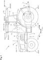
- FIG. 1 is a side view showing a working vehicle 1 according to an embodiment of the present invention
- FIG. 2 is a plan view showing the working vehicle 1 according to the embodiment.
- the working vehicle 1 according to the embodiment is a tractor 1, the embodiment will be explained below assuming that the working vehicle 1 is a tractor 1.
- the working vehicle 1 is not limited to tractors.
- a forward direction of a driver sitting on a driver seat 11 of the tractor 1 (a direction of an arrowed line A1 in FIG. 1 and FIG. 2 ) is referred to as the front
- a rearward direction of the driver (a direction of an arrowed line A2 in FIG. 1 and FIG. 2 ) is referred to as the rear
- a leftward direction of the driver (a direction of an arrowed line B1 in FIG. 2 ) is referred to as the left
- a rightward direction of the driver (a direction of an arrowed line B2 in FIG. 2 ) is referred to as the right.
- a horizontal direction (a direction of an arrowed line K2 in FIG. 2 ) orthogonal to a fore-and-aft direction (a direction of an arrowed line K1 in FIG. 1 and FIG. 2 ) of the tractor 1 is referred to as a machine width direction.
- the tractor 1 has a vehicle body 3, a traveling device 4, and an attachment 5.
- the vehicle body 3 has a vehicle frame 6, a clutch housing 7, and a transmission case 8.
- the vehicle frame 6 extends in the fore-and-aft direction of the vehicle body 3.
- a prime mover 9 is mounted on the vehicle frame 6.
- the prime mover 9 is an engine 9.
- the clutch housing 7 is connected to a rear portion of the engine 9 and houses a clutch.
- the transmission case 8 is connected to a rear portion of the clutch housing 7 and houses a transmission device, a rear-wheel differential device, and the like.
- the transmission device includes a main transmission device and a sub transmission device.
- a PTO shaft 10 protrudes from a rear portion of the vehicle body 3 (behind the transmission case 8).
- the traveling device 4 has front wheels 4F located at a front portion of the vehicle body 3 and rear wheels 4R located at a rear portion of the vehicle body 3.
- the front wheels 4F are supported by the vehicle frame 6.
- the rear wheels 4R are supported by an output shaft of the rear-wheel differential device.
- the vehicle body 3 and the traveling device 4 constitute a traveling body 2 configured to travel.
- a driver seat 11 and a cabin 12 that surrounds the driver seat 11 are mounted on the vehicle body 3.
- a steering wheel 13 is located in front of the driver seat 11.
- the steering wheel 13 is linked to the left and right front wheels 4F with a power steering mechanism.
- a display 14 is located on surroundings (right front) of the driver seat 11.
- the display 14 is constituted of, for example, a touch panel type liquid crystal display (a liquid crystal monitor).
- a hood 16 is located at a front portion of the vehicle body 3.
- the hood 16 forms an engine compartment that houses the engine 9 and other components in the front portion of the vehicle body 4.
- the hood 16 is provided openably so that the front portion can be raised and lowered with the rear portion as a fulcrum.
- the attachment 5 is located at a rear portion of the vehicle body 3.
- the attachment 5 connects a ground working machine, which performs working on the ground (an agricultural field), to a rear portion of the tractor 1.
- the ground working machine is driven by a driving power transmitted from the PTO shaft 10.
- Rotary cultivators, grass cutters, sprayers (spraying fertilizers, chemicals, and the like), and sowing machines can be exemplified as the ground working machine, but the ground working machine is not limited thereto.
- the attachment 5 is a lifting device configured to be driven by an actuator such as a hydraulic cylinder to lift and lower the ground working machine.
- the attachment 5 is constituted of a three-point linkage mechanism.
- the tractor 1 has a plurality of illumination lamps 17.
- the plurality of illumination lamps 17 are located on the traveling body 2.
- the plurality of illumination lamps 17 respectively illuminate different directions.
- the plurality of illumination lamps 17 include a head lamp 18 and a work lamp 19.
- the head lamp 18 is located at a front portion of the traveling body 2.
- the head lamp 18 includes a first head lamp 18A and a second head lamp 18B.
- the first head lamp 18A is located leftward on a front portion of the hood 16 and is capable of illuminating a left area in front of the tractor 1.
- the second head lamp 18B is located rightward on the front portion of the hood 16 and is capable of illuminating a right area in front of the tractor 1.
- a work lamp 19 is located on a roof 12a, which constitutes an upper portion of the cabin 12.
- the work lamp 19 includes a first work lamp 19A, a second work lamp 19B, a third work lamp 19C, a fourth work lamp 19D, a fifth work lamp 19E, and a sixth work lamp 19F.
- Each of the work lamps (that is, the first work lamp 19A, the second work lamp 19B, the third work lamp 19C, the fourth work lamp 19D, the fifth work lamp 19E, and the sixth work lamp 19F) are arranged in an inclining posture in which an illuminating direction is obliquely downward.
- the first work lamp 19A is located leftward on a front portion of the roof 12a and capable of illuminating an obliquely-leftward area in front of the tractor 1.
- the second work lamp 19B is located rightward on the front portion of the roof 12a and capable of illuminating an obliquely-rightward area in front of the tractor 1.
- the third work lamp 19C is located on a left portion of the roof 12a and capable of illuminating a left area of the tractor 1.
- the fourth work lamp 19D is located on a right portion of the roof 12a and capable of illuminating a right area of the tractor 1.
- the fifth work lamp 19E is located leftward on a rear portion of the roof 12a and capable of illuminating an obliquely-leftward area behind the tractor 1.
- the sixth work lamp 19E is located rightward on the rear portion of the roof 12a and capable of illuminating an obliquely-rightward area behind the tractor 1.
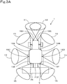
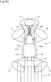
- FIG. 3A is a plan view schematically showing illuminating directions and illuminating areas of the illumination lamps 17 (that is, the head lamps 18 and work lamps 19).
- the illuminating direction and illuminating area of the first head lamp 18A is indicated by a reference symbol XI.
- the illuminating direction and illuminating area of the second head lamp 18B are indicated by a reference symbol X2.
- the illuminating direction and illuminating area of the first work lamp 19A are indicated by a reference symbol Y1.
- the illuminating direction and illuminating area of the second work lamp 19B are indicated by a reference symbol Y2.
- the illuminating direction and illuminating area of the third work lamp 19C are indicated by a reference symbol Y3.
- the illuminating direction and illuminating area of the fourth work lamp 19D are indicated by a reference symbol Y4.
- the illuminating direction and illuminating area of the fifth work lamp 19E are indicated by a reference symbol Y5.
- the illuminating direction and illuminating area of the sixth work lamp 19F are indicated by a reference symbol Y6.
- the illuminating direction and illuminating area shown in FIG. 3A are just exemplified for the purpose of explanation, and can be changed as necessary.
- the illumination lamps 17 (that is, the head lamp 18 and the work lamp 19) have an illuminance changing mechanism configured to change the illuminances (brightness) thereof.
- the illumination lamps 17 (that is, the head lamp 18 and the work lamp 19) may have an orientation changing mechanism configured to change the illuminating directions thereof.
- the tractor 1 has a plurality of cameras 20.
- the plurality of cameras 20 are located on the traveling body 2 and capture images of the surroundings of the traveling body 2.
- the cameras 20 are located on the roof 12a of the cabin 12.
- the cameras 20 are, for example, wide-angle CCD cameras for visible light.
- the camera 20 includes a first camera 20A, a second camera 20B, a third camera 20C, and a fourth camera 20D.
- Each of the cameras (that is, the first camera 20A, the second camera 20B, the third camera 20C, and the fourth camera 20D) is arranged in an inclining posture in which a capturing direction is obliquely downward.
- the first camera 20A is located at the front portion of the roof 12a and between the first work lamp 19A and the second work lamp 19B, and is capable of capturing an area in front of the tractor 1.
- the second camera 20B is located at the left portion of the roof 12a and in the vicinity of the third work lamp 19C, and is capable of capturing a left area of the tractor 1.
- the third camera 20C is located at the right portion of the roof 12a and in the vicinity of the fourth work lamp 19D, and is capable of capturing a right area of the tractor 1.
- the fourth camera 20D is located at the rear portion of the roof 12a and between the fifth work lamp 19E and the sixth work lamp 19F, and is capable of capturing an area behind the tractor 1.
- the number of work lamps 19 is six, but the number is not limited to six, as long as the work lamps are capable of emitting lights to at least the front, rear, left, and right of the tractor 1.
- the number of work lamps 19 may be four or eight.
- the number and directions of the work lamps 19 should be determined to the number and directions in which the lights can be emitted to all the areas captured by the plurality of cameras 20.
- the number of cameras 20 is four, but it is not limited to four, and may be five or more (for example, six or eight). However, the number and directions of the cameras 20 are determined to the number and directions in which at least the front, rear, left and right areas of the tractor 1 can be captured.
- the tractor 1 has an illuminance sensor 21.
- the illuminance sensor 21 is located on the traveling body 2 and measures illuminance of the surroundings of the traveling body 2.
- the illuminance sensor 21 includes a first illuminance sensor 21A to measure illuminance in the capturing directions of the cameras 20, and a second illuminance sensor 21B to measure illuminance in a direction (for example, above the cabin 12) other than the capturing directions of the cameras 20.
- the illuminance measured by the first illuminance sensor 21A is larger (brighter) than the illuminance measured by the second illuminance sensor 21B.
- the tractor 1 has a controller (ECU) 15 to control a traveling system and a working system.
- the controller 15 has a computing unit (that is, CPU or the like) and a storage unit (that is, a memory), and the like, and executes each of controls to be described below based on various types of control programs stored in the storage unit.
- the controller 15 controls the traveling system, the working system, and the like of the tractor 1 based on operation signals outputted when various types of operation tools (that is, levers, switches, dials, and the like) 27 located around the driver seat 11 are operated and on detection signals of various types of detection means (that is, sensors and the like) 28 mounted on the vehicle body 3, the ground working machine, and the like.
- the controller 15 changes the control relating to a way of lighting the illumination lamps 17 (that is, the head lamp 18 and the work lamps 19) in autonomous traveling of the tractor 1 (traveling body 2).
- the changing of control relating to a way of lighting of the illumination lamps 17 includes a control to switch the illumination lamps 17 from being extinguished to being lighted, a control to switch the illumination lamps 17 from being lighted to being extinguished, and a control to change illuminances (brightness) of the illumination lamps 17.
- the controller 15 has a traveling controller 15a and a working controller 15b.
- the traveling controller 15a has a control program for performing a control relating to traveling, and performs a control relating to traveling of the vehicle body 3 based on the control program.
- the traveling controller 15a executes, for example, a control of revolving speed of the engine 9 based on a detection signal output from the accelerator pedal sensor, which is one of the detection means 28, and a control of a forward-backward switching device based on a detection signal output from the forward-backward switching lever, which is one of the operation tools 27.
- the working controller 15b has a control program for executing a control relating to the ground working machine, and executes the control relating to the ground working machine.
- the working controller 15b for example, executes a control relating to lifting and lowering of the attachment 5 (that is, lifting and lowering of the ground working machine) based on an operation signal output from the operation tool 27.
- the tractor 1 has a positioning device 22 and an autonomous steering device 23.
- the positioning device 22 measures a position and azimuth of the traveling body 2 (that is, the vehicle body 3) with the Global Navigation Satellite System (referred to as GNSS). In detail, the positioning device 22 acquires a position and orientation of the traveling body 2 (that is, the vehicle body 3) based on positioning data acquired by receiving radio waves from the GNSS satellites and other positioning data transmitted from a reference station.
- GNSS Global Navigation Satellite System
- the positioning device 22 has a receiving device and an inertial measurement unit (referred to as IMU).
- the receiving device has an antenna or the like and receives satellite signals transmitted from the positioning satellites.
- the receiver device is attached, for example, to an upper portion of the cabin 12 of the vehicle body 3.
- the inertial measurement unit has an acceleration sensor to detect an acceleration, a gyro sensor to detect an angular velocity, and the like.
- the inertial measurement unit is located below the driver seat 11 of the vehicle body 3, for example, and is capable of detecting a roll angle, a pitch angle, a yaw angle, and the like of the traveling body 2.
- the autonomous steering device 23 steers the left and right front wheels 4F by maintaining or changing a rotation angle of a rotation shaft of a steering motor of a power steering unit based on a control signal output from the controller 15.
- the tractor 1 has a changeover switch, one of the operation tools 27, capable of switching between a manual driving mode and the autonomous driving mode.
- the controller 15 has an autonomous traveling controller 15c to perform a control relating to autonomous traveling of the traveling body 2 when the changeover switch is switched to the automatic driving mode.
- the autonomous traveling controller 15c has a control program for performing a control relating to autonomous traveling of the traveling body 2, and performs a control relating to autonomous traveling of the traveling body 2 based on the control program.
- the autonomous traveling controller 15c outputs control signals to the traveling controller 15a and the autonomous steering device 23 based on positioning results by the positioning device 22, a target traveling route preliminarily determined, and the like.
- the target traveling route is, for example, provided by converting a traveling route of preliminary manual driving into data based on positioning results by the positioning device 22, and is stored in a storage of the controller 15.
- FIG. 5 is a view showing an example of a target traveling route R1 determined in an agricultural field HI.
- the traveling controller 15a controls operations of devices of the traveling system such as the transmission device and a brake controller 29, and the autonomous steering device 23 steers the left and right front wheels 4F.
- the autonomous traveling controller 15c controls a traveling speed (that is, a vehicle speed) of the tractor 1 (that is, the traveling body 2) by changing the gear shifts of the transmission device, and controls a traveling direction of the tractor 1 (that is, the traveling body 2) by steering the left and right front wheels 4F.
- the autonomous traveling controller 15c maintains a rotation angle of a rotation shaft of the steering motor when a deviation between a position of the vehicle body 3 and the target traveling route R1 is less than a threshold value in a state where the tractor 1 is autonomously traveling.
- the tractor 1 When the deviation between the position of the vehicle body 3 and the target traveling route R1 is the threshold value or more and the tractor 1 is positioned leftward relative to the target traveling route R1, a rotation shaft of the steering motor is rotated so that a steering direction of the tractor 1 is orientated to the right.
- the rotation shaft of the steering motor When the deviation between the position of the vehicle body 3 and the target traveling route R1 is the threshold value or more and the tractor 1 is positioned rightward relative to the target traveling route R1, the rotation shaft of the steering motor is rotated so that the steering direction of the tractor 1 is orientated to the left.
- a position on the target traveling route and a vehicle speed of the tractor 1 at the position are preliminarily determined and related to each other, and the autonomous traveling controller 15c controls the vehicle speed of the tractor 1 based on this relation.
- the tractor 1 that is, the traveling body 2 is capable of autonomously traveling on the target traveling route while controlling the traveling direction and the vehicle speed.
- the controller 15 has a traveling direction acquisition unit 15d, a working-trace direction acquisition unit 15e, and an illuminating pattern selector 15f.
- the traveling direction acquisition unit 15d, the working-trace direction acquisition unit 15e, and the illuminating pattern selector 15f each execute processing operations based on a predetermined control program stored in the storage.
- the traveling direction acquisition unit 15d acquires a traveling direction of the tractor 1 based on a current position of the tractor 1 (that is, the traveling body 2) and the target traveling route R1 acquired by the positioning device 22. For example, in FIG. 5 , when the tractor 1 is positioned at point A, the traveling direction acquisition unit 15d acquires "forward" as the traveling direction of the tractor 1. When the tractor 1 is positioned at point B, the traveling direction acquisition unit 15d acquires "rightward” as the traveling direction of the tractor 1. When the tractor 1 is positioned at point C, the traveling direction acquisition unit 15d acquires "leftward" as the traveling direction of the tractor 1.
- the working-trace direction acquisition unit 15e acquires, as the working trace direction, a direction of a working trace (that is, a direction of the working trace relative to a current position of the vehicle body 3), which is a route on which the tractor 1 already traveled, based on a current position of the traveling body 2 and the target traveling route R1 acquired by the positioning device 22.
- the working traces are traces of workings performed by the ground working machine (for example, a rotary cultivator) attached to the attachment 5 of the vehicle body 3.
- the working-trace direction acquisition unit 15e acquires "leftward" and "rearward" as the working-trace directions, which are routes on which the tractor 1 already traveled.
- the illuminating pattern selector 15f selects a specific illuminating pattern from among a plurality of illuminating patterns of the illuminating lamps 17.
- the illuminating patterns and the illuminating pattern selector 15f will be described in detail later.
- the tractor 1 has a monitoring device 24.
- the monitoring device 24 has the camera 20 and an image processing unit 25.
- the camera 20 includes the plurality of cameras (that is, the first camera 20A, the second camera 20B, the third camera 20C, and the fourth camera 20D) described above.
- the image processing unit 25 processes video signals transmitted from the first camera 20A, the second camera 20B, the third camera 20C, and the fourth camera 20D to generate images, and displays the generated images on the display 14.
- the display 14 is located around the driver seat 11 when the tractor 1 travels with an operator sitting on the driver seat 11 (see FIG. 1 ), but when the working vehicle 1 travels without the operator sitting on the driver seat 11, a mobile terminal such as a smart phone (that is, a multi-function mobile phone) or a tablet terminal is used as the display 14.
- the display 14 is a mobile terminal that can be arranged at a position separating from the tractor 1 (that is, the traveling body 2).
- the image processing unit 25 transmits the generated image to the display 14 by wireless communication, and then the display 14 displays the image. This allows an operator to view the images captured by the camera 20 through the mobile terminal (that is, the display 14) outside the tractor 1, and allows the operator to monitor (that is, to remotely monitor) autonomous traveling of the tractor 1 from a remote location.
- the controller 15 has an image quality estimating unit 15g configured to estimate an image quality of an image to be displayed on the display 14.
- the image quality estimating unit 15g estimates an image quality of an image to be displayed on the display 14 based on illuminance measured by the illuminance sensor 21.
- the image quality estimating unit 15g has an image quality estimation program stored in the storage of the controller 15, and estimates an image quality of an image to be displayed on the display 14 based on the program.
- the image quality estimating unit 15g may be included in the display 14 or the monitoring device 24.
- the image quality estimating unit 15g estimates that an image quality of an image to be displayed on the display 14 is "good", which indicates that the image is suitable for recognizing a capturing object.
- the image quality estimating unit 15g estimates that an image quality of an image to be displayed on the display 14 is "poor", which indicates that the image is not suitable for recognizing a capturing obj ect.
- the illuminance in the capturing direction of the camera 20 is too dark or too bright, and thus an image quality of the image captured by the camera 20 and displayed on the display 14 is "poor", which is an image unsuitable for recognizing a capturing object.
- the storage of the controller 15 stores a plurality of illuminating patterns that define combinations of illuminating lamps to be lighted and illuminating lamps to be extinguished among the plurality of lighting lamps 17.
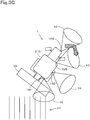
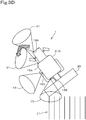
- FIGS. 3A to 3H are views showing examples of the illuminating patterns.
- the illuminating pattern shown in FIG. 3A is called a first illuminating pattern
- the illuminating pattern shown in FIG. 3B is called a second illuminating pattern
- the illuminating pattern shown in FIG. 3C is called a third illuminating pattern
- the illuminating pattern shown in FIG. 3D is called a fourth illuminating pattern
- the illuminating pattern shown in FIG. 3E is called a fifth illuminating pattern
- the illuminating pattern shown in FIG. 3F is called a sixth illuminating pattern
- the illuminating pattern shown in FIG. 3G is called a seventh illuminating pattern
- the illuminating pattern shown in FIG. 3H is called an eighth illuminating pattern.
- the illuminating patterns shown in FIG. 3A to FIG. 3H are just examples of only a part of the plurality of illuminating patterns stored in the storage.
- a rectangle pointed by a reference numeral "26" indicates a ground working machine
- parallel longitudinal lines pointed by a reference sign "Z1" indicates working traces of the ground working machine 26.
- a relationship between the working traces Z1 of the ground working machine 26 and the illuminating patterns will be explained in detail later.
- the first illuminating pattern shown in FIG. 3A is a pattern in which all of the plurality of lighting lamps 17 (that is, the head lamps 18 and the work lamps 19) are lighted.
- the second illuminating pattern shown in FIG. 3B is a pattern in which the first head lamp 18A, the second head lamp 18B, the first work lamp 19A, and the second work lamp 19B are lighted.
- the third illuminating pattern shown in FIG. 3C is a pattern in which the second head lamp 18B, the second work lamp 19B, the fourth work lamp 19D, and the sixth work lamp 19F are lighted.
- the third work lamp 19C, and the fifth work lamp 19E are lighted.
- the fifth illuminating pattern shown in FIG. 3E is a pattern in which the first head lamp 18A, the second head lamp 18B, the first work lamp 19A, the second work lamp 19B, the fifth work lamp 19E, and the sixth work lamp 19F are lighted.
- the sixth illuminating pattern shown in FIG. 3F is a pattern in which the first head lamp 18A, the second head lamp 18B, the first work lamp 19A, the second work lamp 19B, the third work lamp 19C, the fifth work lamp 19E, and the sixth work lamp 19F are lighted.
- 3G is a pattern in which the second work lamp 19B, the fourth work lamp 19D, and the sixth work lamp 19F are lighted.
- the eighth illuminating pattern shown in FIG. 3H is a pattern in which the first head lamp 18A, the second head lamp 18B, the second work lamp 19B, the fourth work lamp 19D, and the sixth work lamp 19F are lighted.
- the storage of the controller 15 stores a plurality of illuminating patterns as an illuminating pattern table T1 (see FIG. 6 ).
- a circle mark indicates the lighting, and a cross mark indicates the extinguishing.
- the illuminating pattern table T1 shown in FIG. 6 is just an example of only a part of the plurality of illuminating patterns.
- the storage of the controller 15 stores a relation table T2 (see FIG. 7 ) that relates the illuminating patterns to the traveling direction of the tractor 1 (that is, the traveling body 2).
- the relation table T2 stores one-to-one relationship between "traveling directions" acquired by the traveling direction acquisition unit 15d and "illuminating patterns" stored in the illuminating pattern table T1.
- the relation table T2 shown in FIG. 7 is just an example of only some of the relationships between the traveling directions and the illuminating patterns.
- the relationships between the "traveling directions" and the "illuminating patterns” are determined so that the illuminating lamps 17 to illuminate the traveling direction of the traveling body 2 are lighted. For example, when the traveling body 2 travels forward, the relationship is determined so that the illuminating lamps 17 (for example, the first head lamp 18A, the second head lamp 18B, and the like) to illuminate the front, which is the traveling direction, are lighted. When the traveling body 2 turns in direction, the relationship is determined so that the illumination lamps 17 to illuminate a target direction to be set as a subsequent traveling direction after the turning in direction are lighted.
- the illuminating lamps 17 for example, the first head lamp 18A, the second head lamp 18B, and the like
- the relationship is determined so that the illumination lamps 17 (for example, the fourth work lamp 19D and the like) to illuminate the right direction, which is the target direction to be set as a subsequent traveling direction after the turning in direction, are lighted.
- the illumination lamps 17 for example, the third work lamp 19C and the like
- the "forward" of the traveling direction is related to the "second illuminating pattern" (see FIG. 3B ) in which the illuminating lamps 17 to illuminate the front that is a traveling direction of the traveling body 2 are lighted.
- the "rightward” of the traveling direction is related to the "third illuminating pattern” (see FIG. 3C ) in which the illuminating lamps 17 to illuminate the right that is a traveling direction of the traveling body 2 are lighted.
- the “leftward” of the traveling direction is related to the "fourth illuminating pattern” (see FIG. 3D ) in which the illuminating lamps 17 to illuminate the left that is a traveling direction of the traveling body 2 are lighted.
- the controller 15 Before the traveling body 2 turns in direction, the controller 15 selectively lights at least one of the illumination lamps based on a target traveling route so that the selectively lighted at least one illumination lamp illuminates a target direction to be set as a subsequent traveling direction after the turning in direction among the plurality of illumination lamps 17. Specifically, the illuminating pattern selector 15f of the controller 15 selects one of the illuminating patterns stored in the storage so as to illuminate a target direction to be set as a subsequent traveling direction for the traveling body 2 after the turning in direction.
- a traveling direction detected by the traveling direction acquisition unit 15d is "forward" when the traveling body 2 positions at the point A, and then the illuminating pattern selector 15f selects, from the relation table T2, the "second illuminating pattern” to be selected when the traveling direction is "forward.
- the traveling direction acquired by the traveling direction acquisition unit 15d is "rightward,” and then the illuminating pattern selector 15f selects, from the relation table T2, the "third illuminating pattern” to be selected when the traveling direction is "rightward”.
- the traveling direction acquired by the traveling direction acquisition unit 15d is "leftward," and then the illuminating pattern selector 15f selects, from the relation table T2, the "fourth illuminating pattern" to be selected when the traveling direction is "leftward".
- the illuminating pattern may be selected by the illuminating pattern selector 15f, and the illuminating lamps 17 may be lighted based on the selection.
- the illuminating pattern may be selected by the illuminating pattern selector 15f at the point B or C, and further the illuminating lamps 17 may be lighted based on the selection at the point B or C.
- the illuminating pattern may be selected by the illuminating pattern selector 15f, and the illuminating lamps 17 may be lighted based on the selection.
- a point behind the turning point by a predetermined distance (for example, 1 meter) in the traveling direction is determined as a "specific point," and at the specific point, the illuminating pattern is selected by the illuminating pattern selector 15f, and the illuminating lamps 17 is lighted based on the selection.
- point E behind the point B that is the turning point by a predetermined distance in the traveling direction is determined as the specific point, and the illuminating pattern is selected at the point E, and the illuminating lamps 17 are lighted based on this selection.
- the illuminating lamps 17 to be lighted are lighted according to the selected illuminating pattern and the illuminating lamps 17 to be extinguished are extinguished according to the selected illuminating pattern, based on the illuminating pattern table T1.
- the illuminating pattern selector 15f selects the "second illuminating pattern"
- the first head lamp 18A, the second head lamp 18B, the first work lamp 19A, and the second work lamp 19B are lighted, and the other illuminating lamps are extinguished, as shown in FIG. 3B .
- the illuminating pattern selector 15f selects the "third illuminating pattern 3"
- the second head lamp 18B, the second work lamp 19B, the fourth work lamp 19D, and the sixth work lamp 19F are lighted, and the other illuminating lamps are extinguished, as shown in FIG. 3C .
- the illuminating pattern selector 15f selects the "fourth illuminating pattern”
- the first head lamp 18A, the first work lamp 19A, the third work lamp 19C, and the fifth work lamp 19E are lighted, and the other illuminating lamps are turned off, as shown in FIG. 3D .
- the illuminating lamps 17 to illuminate an area in front of the traveling body 2 can be lighted.
- the traveling body 2 is turning right (when positioning at the point B)
- the illuminating lamps 17 to illuminate a right area beside the traveling body 2 can be lighted.
- the traveling body 2 is turning left (when positioning at the point C)
- the illuminating lamps 17 to illuminate a left area beside the traveling body 2 can be lighted.
- the illuminating lamps 17 to illuminate a target direction to be set as a subsequent traveling direction after the turning in direction can be lighted selectively from among the plurality of illuminating lamps 17.
- the illuminating lamps 17 can illuminate a traveling direction of the tractor 1 before the turning in direction. Accordingly, the operator can reliably confirm the presence or absence of obstacles in the traveling direction of the tractor 1.
- the illuminating pattern selector 15f may be configured to select an illuminating pattern so that the image quality estimated by the image quality estimating unit 15g satisfies a predetermined condition that provides an image quality suitable for recognizing a capturing object.
- the illuminating pattern selector 15f selects, based on a target traveling route, an illuminating pattern in which a traveling direction of the traveling body 2 after the turning in direction is illuminated from among the illuminating patterns stored in the storage, so that an image quality estimated by the image quality estimating unit 15g satisfies a predetermined condition that provides an image quality suitable for recognizing a capturing object.
- the predetermined condition is described as follows; "an illuminance measured by the first illuminance sensor 21A is within a predetermined range, and a difference between the illuminance measured by the first illuminance sensor 21A and illuminance measured by the second illuminance sensor 21B is within another predetermined range”.
- an image quality of image to be displayed on the display 14 is estimated to be "good", which represents that the image is suitable for recognizing a capturing object.
- a plurality of "illuminating patterns” are related to one "traveling direction" in the relation table T2, as shown in FIG. 8 .
- three illuminating patterns that is, the third illuminating pattern, the seventh illuminating pattern, and the eighth illuminating pattern
- the three illuminating patterns respectively provide different illuminances in the traveling direction; the eighth illuminating pattern provides the brightest illuminance (see FIG. 3H ), the third illuminating pattern provides the brighter illuminance (see FIG. 3C ), and the seventh illuminating pattern provides a basic illuminance (see FIG. 3G ), in order of illuminance (brightness).
- the illuminating pattern selector 15f selects one of the illuminating patterns that satisfies the above-mentioned predetermined condition from among the plurality of "illuminating patterns" related to one "traveling direction". For example, an illuminating pattern that satisfies the above-mentioned predetermined condition is selected from among three illuminating patterns (that is, the illuminating pattern 7, the illuminating pattern 3, and the illuminating pattern 8) relative to "rightward" of the traveling direction. For example, when illuminance in a capturing direction is insufficient in the seventh illuminating pattern and when a brightness difference between the capturing direction and other directions is too large in the eighth illuminating pattern, the third illuminating pattern is selected. In this case, the second head lamp 18B, the second work lamp 19B, the fourth work lamp 19D, and the sixth work lamp 19F are lighted, and the other lamps are extinguished, as shown in FIG. 3C .
- the illuminating lamps 17 can illuminate a traveling direction of the tractor 1, and an image captured by the camera 20 and displayed on the display 14 can be suitable for recognizing a capturing object.
- an operator can reliably confirm the presence or absence of obstacles in the traveling direction of the tractor 1.
- the controller 15 may be configured to control illuminances (brightness) and/or illuminating directions of the illumination lamps 17 (that is, the head lamps 18 and the work lamps 19) to be changed.
- the illuminating pattern selector 15f may be configured to select an illuminating pattern so as to illuminate a working trace Z1 of the ground working machine 26 attached to the attachment 5 of the tractor 1.
- the working trace Z1 is, for example, a cultivating trace when the ground working machine 26 is a rotary cultivator, and a mowing trace when the ground working machine 26 is a mower.
- the illuminating pattern selector 15f selects, based on a target traveling route, an illuminating pattern in which a traveling direction of the traveling body 2 after the turning in direction is illuminated from among the illuminating patterns stored in the storage, so that an image quality estimated by the image quality estimating unit 15g satisfies a predetermined condition that provides an image quality suitable for recognizing a capturing object and the working traces Z1 is illuminated.
- an "illuminating pattern” is related to a combination of a "traveling direction” and a " working trace direction " in the relation table T2, as shown in FIG. 9 .
- the fifth illuminating pattern (see FIG. 3E ) is related as the "illuminating pattern” to a combination of "forward” of the traveling direction and “rearward” of the working-trace direction.
- the sixth illuminating pattern (see FIG. 3F ) is related as the "illuminating pattern” to a combination of "forward” of the traveling direction and "leftward and rearward” of the working-trace direction.
- the illuminating pattern selector 15f selects, from the relation table T2, the "sixth illuminating pattern" (see FIG. 3F ) that is an illuminating pattern for the combination of "forward" of the traveling direction and “leftward and rearward” of the working-trace direction since a traveling direction acquired by the traveling direction acquisition unit 15d is "forward” and the working-trace direction acquired by the working-trace direction acquisition unit 15e is "leftward" and "rearward".
- both the traveling direction of the tractor 1 (forward) and the direction of the working traces Z1 (leftward and rearward) are illuminated by the illumination lamps 17 and captured by the camera 20, and the captured images can be confirmed on the display 14.
- an operator can confirm whether a work by the ground working machine 26 is being performed well or not, in addition to the presence or absence of obstacles in the traveling direction of the tractor 1.
- the controller 15 has a grading unit 15h configured to grade clearness of the images captured by the camera 20.
- the controller 15 changes a control relating to a way of lighting of the illumination lamps 17 based on the clearness graded by the grading unit 15h.
- the grading unit 15h has a grading program stored in the storage of the controller 15, and grades the clearness of the image captured by the camera 20 based on the program.
- the display 14 or the monitoring device 24 may include the grading unit 15h.
- the grading unit 15h grades the clearness of the image based on a predetermined index. For example, luminance (lightness or brightness) and contrast are used as the index of clearness. In this case, the grading unit 15h grades the clearness of image based on the luminance and contrast of the image. In the grading based on the luminance of the image, the luminance of the overall image is judged whether to be within a predetermined proper range (hereinafter referred to as a "first proper range").
- a difference in luminance between the brightest area and the darkest area of the image is within a predetermined proper range (hereinafter referred to as a "second proper range"). Specifically, a plurality of areas, for example, are defined in the image, and it is judged whether the difference in luminance between the brightest area and the darkest area is within the second proper range.
- the grading unit 15h grades the clearness of image as "good” when determining that both the luminance and contrast of the image are within the proper range, and grades the clearness of the image as "poor” when determining that at least one of them is out of the proper range.
- the clearness of the image is "good”
- the image captured by the camera 20 and displayed on the display 14 (hereinafter referred to as a “captured image G1”) is a suitable image for recognizing a capturing object.
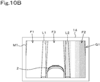
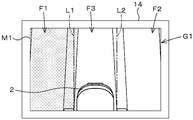
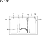
- FIGS. 10A to 10G show examples of captured images G1 captured by the first camera 20A and displayed on the screen M1 of the display 14.
- the camera whose images are graded by the grading unit 15h is not limited to the first camera 20A, but may be the second camera 20B, the third camera 20C, or the fourth camera 20D.
- the shaded areas are the relatively dark areas in the overall image
- the areas drawn by dashed lines are the relatively bright areas in the overall image.
- the first area F1 is a left area of the captured image G1.
- the second area F2 is a right area of the captured image G1.
- the third area F3 is a center area of the captured image G1. That is, the captured image G1 is divided into a plurality
- a virtual line L1 indicates a boundary between the first area F1 and the third area F3, and a virtual line L2 indicates a boundary between the second area F2 and the third area F3.
- the number of and positions of the areas defined in the captured image G1 are not limited to these examples, and can be changed appropriately.
- FIG. 10A shows the captured image G1 of the case where the luminance of the overall image is within a predetermined proper range (hereinafter referred to as the "first proper range”) and the difference in luminance between the brightest area and the darkest area is within a predetermined proper range (hereinafter referred to as the "second proper range”). That is, in the captured image G1, the luminance of the overall image is within the first proper range. In addition, the difference in brightness between the brightest area (for example, the first area F1) and the darkest area (for example, the second area F2) is small and within the second proper range. In this case, the grading unit 15h grades the clearness of the image as "good” since both the luminance and contrast of the image are within the proper ranges.
- the captured image G1 displayed on the display 14 is a suitable image for recognizing a capturing object, and the controller 15 does not change the control relating to a way of lighting of the illumination lamps 17.
- the luminance of the overall image is within the first proper range, but the second area F2 is darker than other areas (the first area F1 and the third area F3), and a difference in brightness between the darkest second area F2 and the brightest area (for example, the first area F1) is out of the second proper range.
- the grading unit 15h grades the clearness of the image as "poor (insufficient luminance in right portion)" because the contrast of the image is out of the proper range due to the darkness of the second area (the right portion).
- the captured image G1 displayed on the display 14 is an image unsuitable for recognizing a capturing object because the right portion is too dark, and the controller 15 changes the control relating a way of lighting of the illumination lamps 17 as described below.
- the luminance of the overall image is within the first proper range, but the first area F1 is darker than other areas (that is, the second area F2 and the third area F3), and the difference in brightness between the darkest first area F1 and the brightest area (for example, the second area F2) is out of the second proper range.
- the grading unit 15h grades the clearness of the image as "poor (insufficient brightness in left portion)" because the contrast of the image is out of the proper range due to the darkness of the second area (the left portion).
- the captured image G1 displayed on the display 14 is an image unsuitable for recognizing a capturing object because the left portion is too dark, and the controller 15 changes the control relating a way of lighting of the illumination lamps 17 as described below.
- the overall image is too dark, but is within the second proper range because the difference in brightness between the brightest area and darkest areas is within the second proper range; however, the luminance of the overall image is out of the first proper range.
- the grading unit 15h grades the clearness of the image as "poor (insufficient luminance in overall)" because the luminance of the overall image is out of the proper range.
- the captured image G1 displayed on the display 14 is an image unsuitable for recognizing a capturing object because the overall image is too dark, and the controller 15 changes the control relating to a way of lighting of the illumination lamps 17 as described below.
- the luminance of the overall image is within the first proper range, but the second area F2 is brighter than the other areas (for example, the first area F1 and the third area F3), and the difference in brightness between the brightest second area F2 and the darkest area (for example, the first area F1) is out of the second proper range.
- the grading unit 15h grades the clearness of the image as "poor (excessive luminance in right portion)" because the contrast of the image is out of the proper range due to the luminance of the second area (the right portion).
- the captured image G1 displayed on the display 14 is an image unsuitable for recognizing a capturing object because the right portion is too bright, and the controller 15 changes the control relating to a way of lighting of the illumination lamps 17 as described below.
- the luminance of the overall image is within the first proper range, but the first area F1 is brighter than other areas (the second area F2 and the third area F3), and the difference in brightness between the brightest first area F1 and the darkest area (for example, the second area F2) is out of the second proper range.
- the grading unit 15h grades the clearness of the image as "poor (excessive luminance in left portion)" because the contrast of the image is out of the proper range due to the luminance of the first area (the left portion).
- the captured image G1 displayed on the display 14 is an image unsuitable for recognizing a capturing object because the left portion is too bright, and the controller 15 changes the control relating to a way of lighting of the illumination lamps 17 as described below.
- the overall image is too bright, and the difference in brightness between the brightest area and the darkest areas is small and thus within the second proper range; however, the luminance of the overall image is out of the first proper range.
- the grading unit 15h grades the clearness of the image as "poor (excessive luminance in overall)" because the luminance of the image is out of the proper range.
- the captured image G1 displayed on the display 14 is an image unsuitable for recognizing a capturing object because the overall image is too bright, and the controller 15 changes the control relating to a way of lighting of the illumination lamps 17 as described below.
- the controller 15 changes the control relating to a way of lighting of the illumination lamps 17 during autonomous traveling. Specifically, one or more of the illumination lamps 17 that illuminate a capturing direction of the camera 20 are selectively lighted, or illuminances of the illumination lamps 17 that illuminate the capturing direction of the camera 20 is changed.
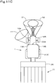
- the grading unit 15h determines the clearness of the image to be "good". In this case, the controller 15 does not make any changes relating to a way of lighting of the illumination lamps 17 based on this grading. That is, among the plurality of lighting lamps 17, the illuminating lamps 17 presently lighted are kept on as they are in an illuminating state (without any change in illuminance), and the illuminating lamps 17 presently extinguished are kept in an extinguished state. Thus, the traveling body 2 continues to travel autonomously with the illuminating pattern shown in FIG. 11A maintained.
- the grading unit 15h grades the clearness of the image as "poor (insufficient luminance in right portion)".
- the controller 15 changes the control relating to a way of lighting of the illumination lamps 17 based on this grading. Specifically, the controller 15 changes the illuminating lamp (for example, the second working light 19B) for illuminating an insufficient luminance direction from the extinguishing state to the illuminating state (see FIG.
- the controller 15 changes the illumination of the illuminating lamp (for example, the second head lamp 18B) illuminating an insufficient luminance direction so that the direction becomes more luminant. In this manner, the right portion of the captured image becomes luminant, resulting in an image with the proper clearness shown in FIG. 10A .
- the grading unit 15h grades the clearness of the image as "poor (insufficient luminance in left portion)".
- the controller 15 changes the control relating to a way of lighting of the illumination lamps 17 based on this grading. Specifically, the controller 15 changes the illuminating lamp (for example, the first work lamp 19A) for illuminating an insufficient luminance direction from the extinguishing state to the illuminating state (see FIG.
- the controller 15 changes the illumination of the illuminating lamp (for example, the first head lamp 18A) illuminating an insufficient luminance direction so that the direction becomes more luminant. In this manner, the left portion of the captured image becomes luminant, resulting in an image with the proper clearness shown in FIG. 10A .
- the grading unit 15h grades the clearness of the image as "poor (insufficient luminance in overall)".
- the controller 15 changes the control relating to a way of lighting of the illumination lamps 17 based on this grading. Specifically, the controller 15 changes the illuminating lamp (for example, the first work lamp 19A) for illuminating an insufficient luminance direction from the extinguishing state to the illuminating state (see FIG.
- the controller 15 changes the illumination of the illuminating lamps (for example, the first head lamp 18A and the second head lamp 18B) illuminating an insufficient luminance direction so that the direction becomes more luminant. In this manner, the overall portion of the captured image becomes luminant, resulting in an image with the proper clearness shown in FIG. 10A .
- the grading unit 15h grades the clearness of the image as "poor (excessive luminance in right portion)".
- the controller 15 changes the control relating to a way of lighting of the illumination lamps 17 based on this grading. Specifically, the controller 15 changes the illuminating lamp (for example, the second work lamp 19B) for illuminating an excessive luminance direction from the illuminating state to the extinguishing state (see FIG.
- the controller 15 changes the illumination of the illuminating lamp (for example, the second work lamp 19B) illuminating an excessive luminance direction so that the direction becomes darker. In this manner, the right portion of the captured image becomes dark, resulting in an image with the proper clearness shown in FIG. 10A .
- the grading unit 15h grades the clearness of the image as "poor (excessive luminance in left portion)".
- the controller 15 changes the control relating to a way of lighting of the illumination lamps 17 based on this grading. Specifically, the controller 15 changes the illuminating lamp (for example, the first work lamp 19A) for illuminating an excessive luminance direction from the illuminating state to the extinguishing state (see FIG.
- the controller 15 changes the illumination of the illuminating lamp (for example, the first work lamp 19A) illuminating an excessive luminance direction so that the direction becomes darker. In this manner, the left portion of the captured image becomes dark, resulting in an image with the proper clearness shown in FIG. 10A .
- the grading unit 15h grades the clearness of the image as "poor (excessive luminance in overall)".
- the controller 15 changes the control relating to a way of lighting of the illumination lamps 17 based on this grading. Specifically, the controller 15 changes the illuminating lamps (for example, the first work lamp 19A and the second work lamp 19B) for illuminating an excessive luminance direction from the illuminating state to the extinguishing state (see FIG.
- the controller 15 changes the illumination of the illuminating lamps (for example, the first head lamp 18A, the second head lamp 18B, the first work lamp 19A, and the second work lamp 19B) illuminating an excessive luminance direction so that the direction becomes darker. In this manner, the left portion of the captured image becomes dark, resulting in an image with the proper clearness shown in FIG. 10A .
- the controller 15 it is preferable to select at least two or more illumination lamps 17 so that light can be irradiated to a capturing object from multiple directions in order to prevent the captured image G1 from capturing shadows and becoming dark.
- the working vehicle 1 includes the traveling body 2 to autonomously travel on the target traveling route R1, the plurality of illumination lamps 17 located on the traveling body 2 and configured to respectively illuminate different directions, and the controller 15 to change a control relating to a way of lighting the illumination lamps 17 in the autonomously traveling.
- the controller 15 is capable of changing the control relating to a way of lighting of the illumination lamps 17 during autonomous traveling, so that appropriate illuminating can be provided to enable an operator to reliably confirm the presence or absence of obstacles on the target traveling route R1 during the autonomous traveling.
- the controller 15 turns on some of the illumination lamps 17 to illuminate a target direction to be set as a subsequent traveling direction after the turning in direction based on the target traveling route R1.
- the working vehicle 1 includes the camera 20 located on the traveling body 2 and configured to capture an image of surroundings of the traveling body 2, the grading unit 15h to grade clearness of the image captured by the camera 20, and the display 14 to display the image captured by the camera 20.
- the controller 15 changes the control relating to a way of lighting the illumination lamps 17 based on the clearness graded by the grading unit 15h.
- the controller 15 can eliminate the excessive or insufficient luminance by changing the control relating to a way of lighting of the illumination lamps 17. In this manner, the image by the camera 20 becomes clear, and a clear image can be displayed on the display 14.
- controller 15 selects and turns on one or more of the illumination lamps illuminating a capturing direction of the camera, based on the clearness graded by the grading unit 15h.
- the controller 15 selects and turns on one or more of the plurality of illumination lamps that illuminate the capturing direction of the camera 20, thereby eliminating excessive or insufficient luminance to eliminate unclearness of the image.
- controller 15 changes an illuminance of the illumination lamp 17 illuminating the capturing direction of the camera 20, based on the clearness graded by the grading unit 15h.
- the controller 15 changes illuminance of the illumination lamp 17 illuminating the capturing direction of the camera 20, thereby eliminating the excessive or insufficient luminance to eliminate unclearness of the image.
- the controller 15 includes the storage to store a plurality of illuminating patterns each of which defines a combination of the illumination lamps 17 including one or more illumination lamps to be lighted and one or more illumination lamps to be extinguished, and the illuminating pattern selector 15f to select, based on the target traveling route, one of the illuminating patterns stored in the storage so as to illuminate the target direction to be set as the subsequent traveling direction after the traveling body 2 turns in direction.
- the illuminating pattern selector 15f selects the most suitable illuminating pattern from a plurality of illuminating patterns, thereby appropriately illuminating a traveling direction of the traveling body 2 without a complicated control.
- the working vehicle 1 includes the illuminance sensor 21 to measure an illuminance around the traveling body 2.
- the illuminating pattern selector 15f selects one of the illuminating patterns based on the illuminance measured by the illuminance sensor 21.
- an illuminating pattern is selected based on illuminance around the traveling body 2, and thus the traveling direction of the traveling body 2 can be illuminated in appropriate illuminance.
- the working vehicle 1 includes the camera 20 located on the traveling body 2 and configured to capture an image of surroundings of the traveling body2, and the display 14 to display the image captured by the camera 20.
- the controller 15 includes the image quality estimating unit 15g to estimate, based on the illuminance measured by the illuminance sensor 20, an image quality of an image to be displayed on the display 14, and the illuminating pattern selector 15f selects one of the illuminating patterns so that the image quality estimated by the image quality estimating unit 15g satisfies a predetermined condition where the image quality can be suitable for recognition of a capturing object.
- the illuminating pattern selector 15f selects an illuminating pattern to satisfy a predetermined condition in which an image quality estimated by the image quality estimating unit 15g can be suitable for recognizing a capturing object, thus an image displayed on the display 14 can have a good image quality suitable for recognizing the capturing object, and thereby an operator viewing the display 14 can stably recognize obstacles and other objects.
- the working vehicle 1 includes the cabin 12 mounted on the traveling body 12.
- the illumination lamps 17 include a plurality of work lamps 19 attached to an upper portion of the cabin 12.
- the plurality of work lamps 19 attached to an upper portion of the cabin 12 can illuminate a traveling direction after turning in direction; thus, the traveling direction can be reliably illuminated without new special illuminating lamps.
- the illumination lamps 17 include a plurality of head lamps 18 attached to a front portion of the traveling body 2.
- the plurality of work lamps 19 attached to the upper portion of the cabin 12 and the plurality of head lamps 18 attached to a front portion of the traveling body 2 can illuminate a traveling direction after turning in direction; thus the traveling direction can be reliably illuminated.
- the display 14 is a mobile terminal capable of being arranged at a position separating from the traveling body 2.
- an operator can view an image captured by the camera 20 via the display (that is, a mobile terminal) 14 at a distance from the traveling body 2. Accordingly, it is possible to monitor (that is, to remotely monitor) autonomous traveling of the tractor 1 from a remote location by viewing the display 14 that displays clear images with appropriate illumination.
Landscapes
- Engineering & Computer Science (AREA)
- Mechanical Engineering (AREA)
- Physics & Mathematics (AREA)
- General Physics & Mathematics (AREA)
- Multimedia (AREA)
- Life Sciences & Earth Sciences (AREA)
- Signal Processing (AREA)
- Soil Sciences (AREA)
- Environmental Sciences (AREA)
- Aviation & Aerospace Engineering (AREA)
- Electromagnetism (AREA)
- Radar, Positioning & Navigation (AREA)
- Remote Sensing (AREA)
- Automation & Control Theory (AREA)
- Computer Vision & Pattern Recognition (AREA)
- Lighting Device Outwards From Vehicle And Optical Signal (AREA)
- Guiding Agricultural Machines (AREA)
- Exposure Control For Cameras (AREA)
- Stroboscope Apparatuses (AREA)
- Indication In Cameras, And Counting Of Exposures (AREA)
- Closed-Circuit Television Systems (AREA)
- Control Of Position, Course, Altitude, Or Attitude Of Moving Bodies (AREA)
Abstract
Description
- The present invention relates to a working vehicle having illumination lamps.
- A working vehicle disclosed in
Patent document 1 is known. - The working vehicle disclosed in
Patent document 1 has a camera device to capture surroundings of the vehicle, an illuminance sensor that detects illuminance in a capturing direction of the camera device, an illuminating device to illuminate the capturing direction of the camera device, and a camera module controller to control these components. The camera module controller has an illuminating device automatic lighting means to automatically light the illuminating device for lighting when an illuminance detected by the illuminance sensor is lower than a predetermined illuminance. - [Patent document 1]
Japanese Unexamined Patent Application Publication No. 2014-36399 - When a working vehicle is a vehicle configured to autonomously travel on a target traveling route, an operator has to check whether there is an obstacle in a traveling direction by viewing an image of an onboard camera at a position separating from the vehicle. However, in the disclosed technology mentioned above, the camera image may become unclear due to excessive or insufficient illuminance by an illuminating device, and the operator may be unable to check the image sufficiently during the autonomous traveling. In addition, when the vehicle turns in direction, it is difficult to appropriately illuminate the traveling direction in advance after turning in direction, which may lead the operator to insufficient confirmation.
- In view of the above-mentioned problem, the present invention intends to provide a working vehicle configured to autonomously travel on a target traveling route, the working vehicle being capable of appropriately performing illumination in autonomous traveling to enable an operator to reliably confirm presence of obstacles or the like on the target traveling route.
- In an aspect of the present invention, a working vehicle includes a traveling body to autonomously travel on a target traveling route, a plurality of illumination lamps located on the traveling body and configured to respectively illuminate different directions, and a controller to change a control relating to a way of lighting the illumination lamps in the autonomously traveling.
- Before the traveling body turns in direction, the controller selectively lights at least one of the illumination lamps based on the target traveling route so that the selectively lighted at least one illumination lamp illuminates a target direction to be set as a subsequent traveling direction after the turning in direction.
- The working vehicle includes a camera located on the traveling body and configured to capture an image of surroundings of the traveling body, a grading unit to grade clearness of the image captured by the camera, and a display to display the image captured by the camera. The controller changes the control relating to the way of lighting the illumination lamps based on the clearness graded by the grading unit.
- The controller selectively lights at least one of the illumination lamps to illuminate a capturing direction of the camera, based on the clearness graded by the grading unit.
- The controller changes an illuminance of the illumination lamp illuminating the capturing direction of the camera, based on the clearness graded by the grading unit.
- The controller includes a storage to store a plurality of illuminating patterns each of which defines a combination of the illumination lamps including one or more illumination lamps to be lighted and other one or more illumination lamps to be extinguished, and an illuminating pattern selector to select, based on the target traveling route, one of the illuminating patterns stored in the storage so as to illuminate a target direction to be set as a subsequent traveling direction for the traveling body after the turning in direction.
- The working vehicle includes an illuminance sensor to measure an illuminance around the traveling body. The illuminating pattern selector selects one of the illuminating patterns based on the illuminance measured by the illuminance sensor.
- The working vehicle includes a camera located on the traveling body and configured to capture an image of surroundings of the traveling body, and a display to display the image captured by the camera. The controller includes an image quality estimating unit to estimate, based on the illuminance measured by the illuminance sensor, an image quality of an image to be displayed on the display, and the illuminating pattern selector selects one of the illuminating patterns so that the image quality estimated by the image quality estimating unit satisfies a predetermined condition where the image quality fits for recognition of a captured obj ect.
- The working vehicle includes a cabin mounted on the traveling body, the illumination lamps include a plurality of work lamps attached to an upper portion of the cabin.
- The illumination lamps include a plurality of head lamps attached to a front portion of the traveling body.
- The display is a mobile terminal capable of being arranged at a position separating from the traveling body.
- According to the above-mentioned working vehicle, in a working vehicle configured to autonomously travel on a target traveling route, a controller is capable of changing a control relating to a way of lighting illumination lamps in autonomous traveling, thereby appropriately performing illumination in autonomous traveling to enable an operator to reliably confirm presence of obstacles or the like on the target traveling route.
-
-
FIG. 1 is a side view showing a working vehicle according to an embodiment of the present invention. -
FIG. 2 is a plan view showing the working vehicle according to the embodiment of the present invention. -
FIG. 3A is a plan view showing an example of an illuminating pattern of illumination lamp (a first illuminating pattern). -
FIG. 3B is a plan view showing an example of the illuminating pattern of illumination lamp (a second illuminating pattern). -
FIG. 3C is a plan view showing an example of the illuminating pattern of illumination lamp (a third illuminating pattern). -
FIG. 3D is a plan view showing an example of the illuminating pattern of illumination lamp (a fourth illuminating pattern). -
FIG. 3E is a plan view showing an example of the illuminating pattern of illumination lamp (a fifth illuminating pattern). -
FIG. 3F is a plan view showing an example of the illuminating pattern of illumination lamp (a sixth illuminating pattern). -
FIG. 3G is a plan view showing an example of the illuminating pattern of illumination lamp (a seventh illuminating pattern). -
FIG. 3H is a plan view showing an example of the illuminating pattern of illumination lamp (an eighth illuminating pattern). -
FIG. 4 is a block diagram showing a schematic diagram of a control system of the working vehicle according to the present invention. -
FIG. 5 is a view showing an example of a target traveling route determined in an agricultural field. -
FIG. 6 is a view showing an example of an illuminating pattern table. -
FIG. 7 is a view showing an example of a relation table. -
FIG. 8 is a view showing another example of the relation table. -
FIG. 9 is a view showing further another example of the relation table. -
FIG. 10A is a view showing an example of a captured image displayed on a screen of a display. -
FIG. 10B is a view showing an example of a captured image displayed on the screen of the display. -
FIG. 10C is a view showing an example of a captured image displayed on the screen of the display. -
FIG. 10D is a view showing an example of a captured image displayed on the screen of the display. -
FIG. 10E is a view showing an example of a captured image displayed on the screen of the display. -
FIG. 10F is a view showing an example of a captured image displayed on the screen of the display. -
FIG. 10G is a view showing an example of a captured image displayed on the screen of the display. -
FIG. 11A is an explanation view of changing a control relating to a way of lighting illumination lamps by a controller. -
FIG. 11B is an explanation view of changing the control relating to the way of lighting the illumination lamps by the controller. -
FIG. 11C is an explanation view of changing the control relating to the way of lighting the illumination lamps by the controller. -
FIG. 11D is an explanation view of changing the control relating to the way of lighting the illumination lamps by the controller. - With reference to the drawings, an embodiment of the present invention will be described below.
-
FIG. 1 is a side view showing a workingvehicle 1 according to an embodiment of the present invention, andFIG. 2 is a plan view showing the workingvehicle 1 according to the embodiment. The workingvehicle 1 according to the embodiment is atractor 1, the embodiment will be explained below assuming that the workingvehicle 1 is atractor 1. However, the workingvehicle 1 is not limited to tractors. - In the following description, a forward direction of a driver sitting on a
driver seat 11 of the tractor 1 (a direction of an arrowed line A1 inFIG. 1 andFIG. 2 ) is referred to as the front, a rearward direction of the driver (a direction of an arrowed line A2 inFIG. 1 andFIG. 2 ) is referred to as the rear, a leftward direction of the driver (a direction of an arrowed line B1 inFIG. 2 ) is referred to as the left, and a rightward direction of the driver (a direction of an arrowed line B2 inFIG. 2 ) is referred to as the right. In the description, a horizontal direction (a direction of an arrowed line K2 inFIG. 2 ) orthogonal to a fore-and-aft direction (a direction of an arrowed line K1 inFIG. 1 andFIG. 2 ) of thetractor 1 is referred to as a machine width direction. - As shown in
FIGS. 1 and2 , thetractor 1 has avehicle body 3, a travelingdevice 4, and anattachment 5. Thevehicle body 3 has avehicle frame 6, aclutch housing 7, and atransmission case 8. Thevehicle frame 6 extends in the fore-and-aft direction of thevehicle body 3. Aprime mover 9 is mounted on thevehicle frame 6. In this embodiment, theprime mover 9 is anengine 9. Theclutch housing 7 is connected to a rear portion of theengine 9 and houses a clutch. Thetransmission case 8 is connected to a rear portion of theclutch housing 7 and houses a transmission device, a rear-wheel differential device, and the like. The transmission device includes a main transmission device and a sub transmission device. APTO shaft 10 protrudes from a rear portion of the vehicle body 3 (behind the transmission case 8). - The traveling
device 4 hasfront wheels 4F located at a front portion of thevehicle body 3 andrear wheels 4R located at a rear portion of thevehicle body 3. Thefront wheels 4F are supported by thevehicle frame 6. Therear wheels 4R are supported by an output shaft of the rear-wheel differential device. Thevehicle body 3 and the travelingdevice 4 constitute a travelingbody 2 configured to travel. - A
driver seat 11 and acabin 12 that surrounds thedriver seat 11 are mounted on thevehicle body 3. Asteering wheel 13 is located in front of thedriver seat 11. Thesteering wheel 13 is linked to the left and rightfront wheels 4F with a power steering mechanism. Adisplay 14 is located on surroundings (right front) of thedriver seat 11. Thedisplay 14 is constituted of, for example, a touch panel type liquid crystal display (a liquid crystal monitor). - A
hood 16 is located at a front portion of thevehicle body 3. Thehood 16 forms an engine compartment that houses theengine 9 and other components in the front portion of thevehicle body 4. - The
hood 16 is provided openably so that the front portion can be raised and lowered with the rear portion as a fulcrum. - The
attachment 5 is located at a rear portion of thevehicle body 3. Theattachment 5 connects a ground working machine, which performs working on the ground (an agricultural field), to a rear portion of thetractor 1. The ground working machine is driven by a driving power transmitted from thePTO shaft 10. Rotary cultivators, grass cutters, sprayers (spraying fertilizers, chemicals, and the like), and sowing machines can be exemplified as the ground working machine, but the ground working machine is not limited thereto. Theattachment 5 is a lifting device configured to be driven by an actuator such as a hydraulic cylinder to lift and lower the ground working machine. Theattachment 5 is constituted of a three-point linkage mechanism. - As shown in
FIGS. 1 and2 , thetractor 1 has a plurality ofillumination lamps 17. - The plurality of
illumination lamps 17 are located on the travelingbody 2. The plurality ofillumination lamps 17 respectively illuminate different directions. The plurality ofillumination lamps 17 include ahead lamp 18 and awork lamp 19. - The
head lamp 18 is located at a front portion of the travelingbody 2. Thehead lamp 18 includes afirst head lamp 18A and asecond head lamp 18B. Thefirst head lamp 18A is located leftward on a front portion of thehood 16 and is capable of illuminating a left area in front of thetractor 1. Thesecond head lamp 18B is located rightward on the front portion of thehood 16 and is capable of illuminating a right area in front of thetractor 1. - A
work lamp 19 is located on aroof 12a, which constitutes an upper portion of thecabin 12. Thework lamp 19 includes afirst work lamp 19A, asecond work lamp 19B, athird work lamp 19C, afourth work lamp 19D, afifth work lamp 19E, and asixth work lamp 19F. Each of the work lamps (that is, thefirst work lamp 19A, thesecond work lamp 19B, thethird work lamp 19C, thefourth work lamp 19D, thefifth work lamp 19E, and thesixth work lamp 19F) are arranged in an inclining posture in which an illuminating direction is obliquely downward. - The
first work lamp 19A is located leftward on a front portion of theroof 12a and capable of illuminating an obliquely-leftward area in front of thetractor 1. Thesecond work lamp 19B is located rightward on the front portion of theroof 12a and capable of illuminating an obliquely-rightward area in front of thetractor 1. Thethird work lamp 19C is located on a left portion of theroof 12a and capable of illuminating a left area of thetractor 1. Thefourth work lamp 19D is located on a right portion of theroof 12a and capable of illuminating a right area of thetractor 1. Thefifth work lamp 19E is located leftward on a rear portion of theroof 12a and capable of illuminating an obliquely-leftward area behind thetractor 1. Thesixth work lamp 19E is located rightward on the rear portion of theroof 12a and capable of illuminating an obliquely-rightward area behind thetractor 1. -
FIG. 3A is a plan view schematically showing illuminating directions and illuminating areas of the illumination lamps 17 (that is, thehead lamps 18 and work lamps 19). The illuminating direction and illuminating area of thefirst head lamp 18A is indicated by a reference symbol XI. The illuminating direction and illuminating area of thesecond head lamp 18B are indicated by a reference symbol X2. The illuminating direction and illuminating area of thefirst work lamp 19A are indicated by a reference symbol Y1. The illuminating direction and illuminating area of thesecond work lamp 19B are indicated by a reference symbol Y2. The illuminating direction and illuminating area of thethird work lamp 19C are indicated by a reference symbol Y3. The illuminating direction and illuminating area of thefourth work lamp 19D are indicated by a reference symbol Y4. The illuminating direction and illuminating area of thefifth work lamp 19E are indicated by a reference symbol Y5. The illuminating direction and illuminating area of thesixth work lamp 19F are indicated by a reference symbol Y6. - However, the illuminating direction and illuminating area shown in
FIG. 3A are just exemplified for the purpose of explanation, and can be changed as necessary. - It is preferred that the illumination lamps 17 (that is, the
head lamp 18 and the work lamp 19) have an illuminance changing mechanism configured to change the illuminances (brightness) thereof. In addition, the illumination lamps 17 (that is, thehead lamp 18 and the work lamp 19) may have an orientation changing mechanism configured to change the illuminating directions thereof. - As shown in
FIGS. 1 and2 , thetractor 1 has a plurality ofcameras 20. - The plurality of
cameras 20 are located on the travelingbody 2 and capture images of the surroundings of the travelingbody 2. Thecameras 20 are located on theroof 12a of thecabin 12. Thecameras 20 are, for example, wide-angle CCD cameras for visible light. Thecamera 20 includes afirst camera 20A, asecond camera 20B, athird camera 20C, and afourth camera 20D. Each of the cameras (that is, thefirst camera 20A, thesecond camera 20B, thethird camera 20C, and thefourth camera 20D) is arranged in an inclining posture in which a capturing direction is obliquely downward. - The
first camera 20A is located at the front portion of theroof 12a and between thefirst work lamp 19A and thesecond work lamp 19B, and is capable of capturing an area in front of thetractor 1. Thesecond camera 20B is located at the left portion of theroof 12a and in the vicinity of thethird work lamp 19C, and is capable of capturing a left area of thetractor 1. Thethird camera 20C is located at the right portion of theroof 12a and in the vicinity of thefourth work lamp 19D, and is capable of capturing a right area of thetractor 1. Thefourth camera 20D is located at the rear portion of theroof 12a and between thefifth work lamp 19E and thesixth work lamp 19F, and is capable of capturing an area behind thetractor 1. - In the embodiment, the number of
work lamps 19 is six, but the number is not limited to six, as long as the work lamps are capable of emitting lights to at least the front, rear, left, and right of thetractor 1. For example, the number ofwork lamps 19 may be four or eight. However, the number and directions of thework lamps 19 should be determined to the number and directions in which the lights can be emitted to all the areas captured by the plurality ofcameras 20. - In the embodiment, the number of
cameras 20 is four, but it is not limited to four, and may be five or more (for example, six or eight). However, the number and directions of thecameras 20 are determined to the number and directions in which at least the front, rear, left and right areas of thetractor 1 can be captured. - As shown in
FIG. 4 , thetractor 1 has anilluminance sensor 21. Although not shown in the drawings, theilluminance sensor 21 is located on the travelingbody 2 and measures illuminance of the surroundings of the travelingbody 2. Theilluminance sensor 21 includes afirst illuminance sensor 21A to measure illuminance in the capturing directions of thecameras 20, and asecond illuminance sensor 21B to measure illuminance in a direction (for example, above the cabin 12) other than the capturing directions of thecameras 20. - For example, when the capturing directions of the
cameras 20 are illuminated by theillumination lamps 17 after sunset, the illuminance measured by thefirst illuminance sensor 21A is larger (brighter) than the illuminance measured by thesecond illuminance sensor 21B. - As shown in
FIG. 4 , thetractor 1 has a controller (ECU) 15 to control a traveling system and a working system. Thecontroller 15 has a computing unit (that is, CPU or the like) and a storage unit (that is, a memory), and the like, and executes each of controls to be described below based on various types of control programs stored in the storage unit. Specifically, thecontroller 15 controls the traveling system, the working system, and the like of thetractor 1 based on operation signals outputted when various types of operation tools (that is, levers, switches, dials, and the like) 27 located around thedriver seat 11 are operated and on detection signals of various types of detection means (that is, sensors and the like) 28 mounted on thevehicle body 3, the ground working machine, and the like. In addition, thecontroller 15 changes the control relating to a way of lighting the illumination lamps 17 (that is, thehead lamp 18 and the work lamps 19) in autonomous traveling of the tractor 1 (traveling body 2). The changing of control relating to a way of lighting of theillumination lamps 17 includes a control to switch theillumination lamps 17 from being extinguished to being lighted, a control to switch theillumination lamps 17 from being lighted to being extinguished, and a control to change illuminances (brightness) of theillumination lamps 17. - The
controller 15 has a travelingcontroller 15a and a workingcontroller 15b. - The traveling
controller 15a has a control program for performing a control relating to traveling, and performs a control relating to traveling of thevehicle body 3 based on the control program. - The traveling
controller 15a executes, for example, a control of revolving speed of theengine 9 based on a detection signal output from the accelerator pedal sensor, which is one of the detection means 28, and a control of a forward-backward switching device based on a detection signal output from the forward-backward switching lever, which is one of theoperation tools 27. The workingcontroller 15b has a control program for executing a control relating to the ground working machine, and executes the control relating to the ground working machine. The workingcontroller 15b, for example, executes a control relating to lifting and lowering of the attachment 5 (that is, lifting and lowering of the ground working machine) based on an operation signal output from theoperation tool 27. - The
tractor 1 has apositioning device 22 and anautonomous steering device 23. - The
positioning device 22 measures a position and azimuth of the traveling body 2 (that is, the vehicle body 3) with the Global Navigation Satellite System (referred to as GNSS). In detail, thepositioning device 22 acquires a position and orientation of the traveling body 2 (that is, the vehicle body 3) based on positioning data acquired by receiving radio waves from the GNSS satellites and other positioning data transmitted from a reference station. - The
positioning device 22 has a receiving device and an inertial measurement unit (referred to as IMU). The receiving device has an antenna or the like and receives satellite signals transmitted from the positioning satellites. The receiver device is attached, for example, to an upper portion of thecabin 12 of thevehicle body 3. The inertial measurement unit has an acceleration sensor to detect an acceleration, a gyro sensor to detect an angular velocity, and the like. The inertial measurement unit is located below thedriver seat 11 of thevehicle body 3, for example, and is capable of detecting a roll angle, a pitch angle, a yaw angle, and the like of the travelingbody 2. - The
autonomous steering device 23 steers the left and rightfront wheels 4F by maintaining or changing a rotation angle of a rotation shaft of a steering motor of a power steering unit based on a control signal output from thecontroller 15. - The
tractor 1 has a changeover switch, one of theoperation tools 27, capable of switching between a manual driving mode and the autonomous driving mode. Thecontroller 15 has anautonomous traveling controller 15c to perform a control relating to autonomous traveling of the travelingbody 2 when the changeover switch is switched to the automatic driving mode. Theautonomous traveling controller 15c has a control program for performing a control relating to autonomous traveling of the travelingbody 2, and performs a control relating to autonomous traveling of the travelingbody 2 based on the control program. - The
autonomous traveling controller 15c outputs control signals to the travelingcontroller 15a and theautonomous steering device 23 based on positioning results by thepositioning device 22, a target traveling route preliminarily determined, and the like. The target traveling route is, for example, provided by converting a traveling route of preliminary manual driving into data based on positioning results by thepositioning device 22, and is stored in a storage of thecontroller 15.FIG. 5 is a view showing an example of a target traveling route R1 determined in an agricultural field HI. - Based on the control signals from the autonomous traveling
controller 15c, the travelingcontroller 15a controls operations of devices of the traveling system such as the transmission device and abrake controller 29, and theautonomous steering device 23 steers the left and rightfront wheels 4F. Theautonomous traveling controller 15c controls a traveling speed (that is, a vehicle speed) of the tractor 1 (that is, the traveling body 2) by changing the gear shifts of the transmission device, and controls a traveling direction of the tractor 1 (that is, the traveling body 2) by steering the left and rightfront wheels 4F. Specifically, the autonomous travelingcontroller 15c maintains a rotation angle of a rotation shaft of the steering motor when a deviation between a position of thevehicle body 3 and the target traveling route R1 is less than a threshold value in a state where thetractor 1 is autonomously traveling. When the deviation between the position of thevehicle body 3 and the target traveling route R1 is the threshold value or more and thetractor 1 is positioned leftward relative to the target traveling route R1, a rotation shaft of the steering motor is rotated so that a steering direction of thetractor 1 is orientated to the right. When the deviation between the position of thevehicle body 3 and the target traveling route R1 is the threshold value or more and thetractor 1 is positioned rightward relative to the target traveling route R1, the rotation shaft of the steering motor is rotated so that the steering direction of thetractor 1 is orientated to the left. A position on the target traveling route and a vehicle speed of thetractor 1 at the position are preliminarily determined and related to each other, and the autonomous travelingcontroller 15c controls the vehicle speed of thetractor 1 based on this relation. In this manner, the tractor 1 (that is, the traveling body 2) is capable of autonomously traveling on the target traveling route while controlling the traveling direction and the vehicle speed. - As shown in
FIG. 4 , thecontroller 15 has a travelingdirection acquisition unit 15d, a working-tracedirection acquisition unit 15e, and an illuminatingpattern selector 15f. The travelingdirection acquisition unit 15d, the working-tracedirection acquisition unit 15e, and the illuminatingpattern selector 15f each execute processing operations based on a predetermined control program stored in the storage. - The traveling
direction acquisition unit 15d acquires a traveling direction of thetractor 1 based on a current position of the tractor 1 (that is, the traveling body 2) and the target traveling route R1 acquired by thepositioning device 22. For example, inFIG. 5 , when thetractor 1 is positioned at point A, the travelingdirection acquisition unit 15d acquires "forward" as the traveling direction of thetractor 1. When thetractor 1 is positioned at point B, the travelingdirection acquisition unit 15d acquires "rightward" as the traveling direction of thetractor 1. When thetractor 1 is positioned at point C, the travelingdirection acquisition unit 15d acquires "leftward" as the traveling direction of thetractor 1. - The working-trace
direction acquisition unit 15e acquires, as the working trace direction, a direction of a working trace (that is, a direction of the working trace relative to a current position of the vehicle body 3), which is a route on which thetractor 1 already traveled, based on a current position of the travelingbody 2 and the target traveling route R1 acquired by thepositioning device 22. The working traces are traces of workings performed by the ground working machine (for example, a rotary cultivator) attached to theattachment 5 of thevehicle body 3. For example, inFIG. 5 , when thetractor 1 is positioned at point D, the working-tracedirection acquisition unit 15e acquires "leftward" and "rearward" as the working-trace directions, which are routes on which thetractor 1 already traveled. - The illuminating
pattern selector 15f selects a specific illuminating pattern from among a plurality of illuminating patterns of the illuminatinglamps 17. The illuminating patterns and the illuminatingpattern selector 15f will be described in detail later. - In addition, the
tractor 1 has amonitoring device 24. - As shown in
FIG. 4 , themonitoring device 24 has thecamera 20 and animage processing unit 25. - The
camera 20 includes the plurality of cameras (that is, thefirst camera 20A, thesecond camera 20B, thethird camera 20C, and thefourth camera 20D) described above. - The
image processing unit 25 processes video signals transmitted from thefirst camera 20A, thesecond camera 20B, thethird camera 20C, and thefourth camera 20D to generate images, and displays the generated images on thedisplay 14. - The
display 14 is located around thedriver seat 11 when thetractor 1 travels with an operator sitting on the driver seat 11 (seeFIG. 1 ), but when the workingvehicle 1 travels without the operator sitting on thedriver seat 11, a mobile terminal such as a smart phone (that is, a multi-function mobile phone) or a tablet terminal is used as thedisplay 14. In this case, thedisplay 14 is a mobile terminal that can be arranged at a position separating from the tractor 1 (that is, the traveling body 2). When thedisplay 14 is a mobile terminal, theimage processing unit 25 transmits the generated image to thedisplay 14 by wireless communication, and then thedisplay 14 displays the image. This allows an operator to view the images captured by thecamera 20 through the mobile terminal (that is, the display 14) outside thetractor 1, and allows the operator to monitor (that is, to remotely monitor) autonomous traveling of thetractor 1 from a remote location. - As shown in
FIG. 4 , thecontroller 15 has an imagequality estimating unit 15g configured to estimate an image quality of an image to be displayed on thedisplay 14. The imagequality estimating unit 15g estimates an image quality of an image to be displayed on thedisplay 14 based on illuminance measured by theilluminance sensor 21. The imagequality estimating unit 15g has an image quality estimation program stored in the storage of thecontroller 15, and estimates an image quality of an image to be displayed on thedisplay 14 based on the program. The imagequality estimating unit 15g may be included in thedisplay 14 or themonitoring device 24. - When illuminance measured by the
first illuminance sensor 21A is within a predetermined range and when a difference between illuminance measured by thefirst illuminance sensor 21A and illuminance measured by thesecond illuminance sensor 21B is within another predetermined range, the imagequality estimating unit 15g estimates that an image quality of an image to be displayed on thedisplay 14 is "good", which indicates that the image is suitable for recognizing a capturing object. In addition, when illuminance measured by thefirst illuminance sensor 21A is out of the predetermined range or when a difference between illuminance measured by thefirst illuminance sensor 21A and illuminance measured by thesecond illuminance sensor 21B is out of the predetermined range, the imagequality estimating unit 15g estimates that an image quality of an image to be displayed on thedisplay 14 is "poor", which indicates that the image is not suitable for recognizing a capturing obj ect. - For example, when illuminance measured by the
first illuminance sensor 21A is out of the predetermined range, the illuminance in the capturing direction of thecamera 20 is too dark or too bright, and thus an image quality of the image captured by thecamera 20 and displayed on thedisplay 14 is "poor", which is an image unsuitable for recognizing a capturing object. Even when illuminance measured by thefirst illuminance sensor 21A is out of the predetermined range, the differences in brightness and darkness between the capturing direction and other directions is too large when a difference between illuminance measured by thefirst illuminance sensor 21A and illuminance measured by thesecond illuminance sensor 21B is out of the predetermined range, and thus an image quality of the image captured by thecamera 20 and displayed on thedisplay 14 is "poor", which is unsuitable for recognizing a capturing object. - The storage of the
controller 15 stores a plurality of illuminating patterns that define combinations of illuminating lamps to be lighted and illuminating lamps to be extinguished among the plurality oflighting lamps 17.FIGS. 3A to 3H are views showing examples of the illuminating patterns. For convenience of explanation, the illuminating pattern shown inFIG. 3A is called a first illuminating pattern, the illuminating pattern shown inFIG. 3B is called a second illuminating pattern, the illuminating pattern shown inFIG. 3C is called a third illuminating pattern, the illuminating pattern shown inFIG. 3D is called a fourth illuminating pattern, the illuminating pattern shown inFIG. 3E is called a fifth illuminating pattern, the illuminating pattern shown inFIG. 3F is called a sixth illuminating pattern, the illuminating pattern shown inFIG. 3G is called a seventh illuminating pattern, and the illuminating pattern shown inFIG. 3H is called an eighth illuminating pattern. However, the illuminating patterns shown inFIG. 3A to FIG. 3H are just examples of only a part of the plurality of illuminating patterns stored in the storage. - In addition, in
FIGS. 3B to 3H , a rectangle pointed by a reference numeral "26" indicates a ground working machine, and parallel longitudinal lines pointed by a reference sign "Z1" indicates working traces of theground working machine 26. A relationship between the working traces Z1 of theground working machine 26 and the illuminating patterns will be explained in detail later. - The first illuminating pattern shown in
FIG. 3A is a pattern in which all of the plurality of lighting lamps 17 (that is, thehead lamps 18 and the work lamps 19) are lighted. The second illuminating pattern shown inFIG. 3B is a pattern in which thefirst head lamp 18A, thesecond head lamp 18B, thefirst work lamp 19A, and thesecond work lamp 19B are lighted. The third illuminating pattern shown inFIG. 3C is a pattern in which thesecond head lamp 18B, thesecond work lamp 19B, thefourth work lamp 19D, and thesixth work lamp 19F are lighted. The fourth illuminating pattern shown inFIG. 3D is a pattern in which thefirst head lamp 18A, thefirst work lamp 19A, thethird work lamp 19C, and thefifth work lamp 19E are lighted. The fifth illuminating pattern shown inFIG. 3E is a pattern in which thefirst head lamp 18A, thesecond head lamp 18B, thefirst work lamp 19A, thesecond work lamp 19B, thefifth work lamp 19E, and thesixth work lamp 19F are lighted. The sixth illuminating pattern shown inFIG. 3F is a pattern in which thefirst head lamp 18A, thesecond head lamp 18B, thefirst work lamp 19A, thesecond work lamp 19B, thethird work lamp 19C, thefifth work lamp 19E, and thesixth work lamp 19F are lighted. The seventh illuminating pattern shown inFIG. 3G is a pattern in which thesecond work lamp 19B, thefourth work lamp 19D, and thesixth work lamp 19F are lighted. The eighth illuminating pattern shown inFIG. 3H is a pattern in which thefirst head lamp 18A, thesecond head lamp 18B, thesecond work lamp 19B, thefourth work lamp 19D, and thesixth work lamp 19F are lighted. - The storage of the
controller 15 stores a plurality of illuminating patterns as an illuminating pattern table T1 (seeFIG. 6 ). InFIG. 6 , a circle mark indicates the lighting, and a cross mark indicates the extinguishing. The illuminating pattern table T1 shown inFIG. 6 is just an example of only a part of the plurality of illuminating patterns. - In addition, the storage of the
controller 15 stores a relation table T2 (seeFIG. 7 ) that relates the illuminating patterns to the traveling direction of the tractor 1 (that is, the traveling body 2). The relation table T2 stores one-to-one relationship between "traveling directions" acquired by the travelingdirection acquisition unit 15d and "illuminating patterns" stored in the illuminating pattern table T1. The relation table T2 shown inFIG. 7 is just an example of only some of the relationships between the traveling directions and the illuminating patterns. - The relationships between the "traveling directions" and the "illuminating patterns" are determined so that the illuminating
lamps 17 to illuminate the traveling direction of the travelingbody 2 are lighted. For example, when the travelingbody 2 travels forward, the relationship is determined so that the illuminating lamps 17 (for example, thefirst head lamp 18A, thesecond head lamp 18B, and the like) to illuminate the front, which is the traveling direction, are lighted. When the travelingbody 2 turns in direction, the relationship is determined so that theillumination lamps 17 to illuminate a target direction to be set as a subsequent traveling direction after the turning in direction are lighted. Specifically, when the travelingbody 2 turns in direction to the right (that is, turns right), the relationship is determined so that the illumination lamps 17 (for example, thefourth work lamp 19D and the like) to illuminate the right direction, which is the target direction to be set as a subsequent traveling direction after the turning in direction, are lighted. When the travelingbody 2 turns in direction to the left (that is, turns left), the relationship is determined so that the illumination lamps 17 (for example, thethird work lamp 19C and the like) to illuminate the left direction, which is the target direction to be set as a subsequent traveling direction after the turning in direction, are lighted. - In the relation table T2 shown in
FIG. 7 , the "forward" of the traveling direction is related to the "second illuminating pattern" (seeFIG. 3B ) in which the illuminatinglamps 17 to illuminate the front that is a traveling direction of the travelingbody 2 are lighted. The "rightward" of the traveling direction is related to the "third illuminating pattern" (seeFIG. 3C ) in which the illuminatinglamps 17 to illuminate the right that is a traveling direction of the travelingbody 2 are lighted. The "leftward" of the traveling direction is related to the "fourth illuminating pattern" (seeFIG. 3D ) in which the illuminatinglamps 17 to illuminate the left that is a traveling direction of the travelingbody 2 are lighted. - Before the traveling
body 2 turns in direction, thecontroller 15 selectively lights at least one of the illumination lamps based on a target traveling route so that the selectively lighted at least one illumination lamp illuminates a target direction to be set as a subsequent traveling direction after the turning in direction among the plurality ofillumination lamps 17. Specifically, the illuminatingpattern selector 15f of thecontroller 15 selects one of the illuminating patterns stored in the storage so as to illuminate a target direction to be set as a subsequent traveling direction for the travelingbody 2 after the turning in direction. - For example, in a state where the traveling
body 2 is traveling on the target traveling route R1 shown inFIG. 5 , a traveling direction detected by the travelingdirection acquisition unit 15d is "forward" when the travelingbody 2 positions at the point A, and then the illuminatingpattern selector 15f selects, from the relation table T2, the "second illuminating pattern" to be selected when the traveling direction is "forward. When the travelingbody 2 positions at the point B, the traveling direction acquired by the travelingdirection acquisition unit 15d is "rightward," and then the illuminatingpattern selector 15f selects, from the relation table T2, the "third illuminating pattern" to be selected when the traveling direction is "rightward". When the travelingbody 2 positions at the point C, the traveling direction acquired by the travelingdirection acquisition unit 15d is "leftward," and then the illuminatingpattern selector 15f selects, from the relation table T2, the "fourth illuminating pattern" to be selected when the traveling direction is "leftward". - In the traveling
body 2 that is turning in direction, when the travelingbody 2 reaches a turning point, the illuminating pattern may be selected by the illuminatingpattern selector 15f, and the illuminatinglamps 17 may be lighted based on the selection. For example, in a case where the travelingbody 2 is traveling on the target traveling route R1 shown inFIG. 5 , the illuminating pattern may be selected by the illuminatingpattern selector 15f at the point B or C, and further the illuminatinglamps 17 may be lighted based on the selection at the point B or C. - In the traveling
body 2 that is turning in direction, before the travelingbody 2 reaches the turning, the illuminating pattern may be selected by the illuminatingpattern selector 15f, and the illuminatinglamps 17 may be lighted based on the selection. In this case, a point behind the turning point by a predetermined distance (for example, 1 meter) in the traveling direction is determined as a "specific point," and at the specific point, the illuminating pattern is selected by the illuminatingpattern selector 15f, and the illuminatinglamps 17 is lighted based on the selection. For example, in a state where the travelingbody 2 travels on the target traveling route shown inFIG. 5 , point E behind the point B that is the turning point by a predetermined distance in the traveling direction is determined as the specific point, and the illuminating pattern is selected at the point E, and the illuminatinglamps 17 are lighted based on this selection. - When the illuminating
pattern selector 15f selects one of the illuminating patterns, the illuminatinglamps 17 to be lighted are lighted according to the selected illuminating pattern and the illuminatinglamps 17 to be extinguished are extinguished according to the selected illuminating pattern, based on the illuminating pattern table T1. For example, when the illuminatingpattern selector 15f selects the "second illuminating pattern", thefirst head lamp 18A, thesecond head lamp 18B, thefirst work lamp 19A, and thesecond work lamp 19B are lighted, and the other illuminating lamps are extinguished, as shown inFIG. 3B . When the illuminatingpattern selector 15f selects the "third illuminatingpattern 3", thesecond head lamp 18B, thesecond work lamp 19B, thefourth work lamp 19D, and thesixth work lamp 19F are lighted, and the other illuminating lamps are extinguished, as shown inFIG. 3C . When the illuminatingpattern selector 15f selects the "fourth illuminating pattern", thefirst head lamp 18A, thefirst work lamp 19A, thethird work lamp 19C, and thefifth work lamp 19E are lighted, and the other illuminating lamps are turned off, as shown inFIG. 3D . - In this manner, when the traveling
body 2 is traveling forward (that is, straight ahead) (when positioning at the point A), the illuminatinglamps 17 to illuminate an area in front of the travelingbody 2 can be lighted. When the travelingbody 2 is turning right (when positioning at the point B), the illuminatinglamps 17 to illuminate a right area beside the travelingbody 2 can be lighted. In addition, when the travelingbody 2 is turning left (when positioning at the point C), the illuminatinglamps 17 to illuminate a left area beside the travelingbody 2 can be lighted. Thus, before the travelingbody 2 turns in direction, the illuminatinglamps 17 to illuminate a target direction to be set as a subsequent traveling direction after the turning in direction can be lighted selectively from among the plurality of illuminatinglamps 17. - According to this configuration, in a state where the
tractor 1 turns in direction, the illuminatinglamps 17 can illuminate a traveling direction of thetractor 1 before the turning in direction. Accordingly, the operator can reliably confirm the presence or absence of obstacles in the traveling direction of thetractor 1. - The illuminating
pattern selector 15f may be configured to select an illuminating pattern so that the image quality estimated by the imagequality estimating unit 15g satisfies a predetermined condition that provides an image quality suitable for recognizing a capturing object. In this configuration, the illuminatingpattern selector 15f selects, based on a target traveling route, an illuminating pattern in which a traveling direction of the travelingbody 2 after the turning in direction is illuminated from among the illuminating patterns stored in the storage, so that an image quality estimated by the imagequality estimating unit 15g satisfies a predetermined condition that provides an image quality suitable for recognizing a capturing object. - In the embodiment, the predetermined condition is described as follows; "an illuminance measured by the
first illuminance sensor 21A is within a predetermined range, and a difference between the illuminance measured by thefirst illuminance sensor 21A and illuminance measured by thesecond illuminance sensor 21B is within another predetermined range". As described above, when this condition is satisfied, an image quality of image to be displayed on thedisplay 14 is estimated to be "good", which represents that the image is suitable for recognizing a capturing object. - When adopting this configuration, a plurality of "illuminating patterns" are related to one "traveling direction" in the relation table T2, as shown in
FIG. 8 . In the example shown inFIG. 8 , three illuminating patterns (that is, the third illuminating pattern, the seventh illuminating pattern, and the eighth illuminating pattern) are related to "rightward" of the traveling direction. The three illuminating patterns respectively provide different illuminances in the traveling direction; the eighth illuminating pattern provides the brightest illuminance (seeFIG. 3H ), the third illuminating pattern provides the brighter illuminance (seeFIG. 3C ), and the seventh illuminating pattern provides a basic illuminance (seeFIG. 3G ), in order of illuminance (brightness). - The illuminating
pattern selector 15f selects one of the illuminating patterns that satisfies the above-mentioned predetermined condition from among the plurality of "illuminating patterns" related to one "traveling direction". For example, an illuminating pattern that satisfies the above-mentioned predetermined condition is selected from among three illuminating patterns (that is, the illuminatingpattern 7, the illuminatingpattern 3, and the illuminating pattern 8) relative to "rightward" of the traveling direction. For example, when illuminance in a capturing direction is insufficient in the seventh illuminating pattern and when a brightness difference between the capturing direction and other directions is too large in the eighth illuminating pattern, the third illuminating pattern is selected. In this case, thesecond head lamp 18B, thesecond work lamp 19B, thefourth work lamp 19D, and thesixth work lamp 19F are lighted, and the other lamps are extinguished, as shown inFIG. 3C . - According to this configuration, the illuminating
lamps 17 can illuminate a traveling direction of thetractor 1, and an image captured by thecamera 20 and displayed on thedisplay 14 can be suitable for recognizing a capturing object. Thus, an operator can reliably confirm the presence or absence of obstacles in the traveling direction of thetractor 1. - In this configuration, in order to make the image captured by the
camera 20 and displayed on thedisplay 14 for recognizing a capturing object, thecontroller 15 may be configured to control illuminances (brightness) and/or illuminating directions of the illumination lamps 17 (that is, thehead lamps 18 and the work lamps 19) to be changed. - The illuminating
pattern selector 15f may be configured to select an illuminating pattern so as to illuminate a working trace Z1 of theground working machine 26 attached to theattachment 5 of thetractor 1. The working trace Z1 is, for example, a cultivating trace when theground working machine 26 is a rotary cultivator, and a mowing trace when theground working machine 26 is a mower. In this case, the illuminatingpattern selector 15f selects, based on a target traveling route, an illuminating pattern in which a traveling direction of the travelingbody 2 after the turning in direction is illuminated from among the illuminating patterns stored in the storage, so that an image quality estimated by the imagequality estimating unit 15g satisfies a predetermined condition that provides an image quality suitable for recognizing a capturing object and the working traces Z1 is illuminated. - To adopt this configuration, an "illuminating pattern" is related to a combination of a "traveling direction" and a " working trace direction " in the relation table T2, as shown in
FIG. 9 . In an example shown inFIG. 9 , the fifth illuminating pattern (seeFIG. 3E ) is related as the "illuminating pattern" to a combination of "forward" of the traveling direction and "rearward" of the working-trace direction. In addition, the sixth illuminating pattern (seeFIG. 3F ) is related as the "illuminating pattern" to a combination of "forward" of the traveling direction and "leftward and rearward" of the working-trace direction. - For example, when the traveling
body 2 positions at the point D inFIG. 5 , the illuminatingpattern selector 15f selects, from the relation table T2, the "sixth illuminating pattern" (seeFIG. 3F ) that is an illuminating pattern for the combination of "forward" of the traveling direction and "leftward and rearward" of the working-trace direction since a traveling direction acquired by the travelingdirection acquisition unit 15d is "forward" and the working-trace direction acquired by the working-tracedirection acquisition unit 15e is "leftward" and "rearward". - According to this configuration, both the traveling direction of the tractor 1 (forward) and the direction of the working traces Z1 (leftward and rearward) are illuminated by the
illumination lamps 17 and captured by thecamera 20, and the captured images can be confirmed on thedisplay 14. Thus, an operator can confirm whether a work by theground working machine 26 is being performed well or not, in addition to the presence or absence of obstacles in the traveling direction of thetractor 1. - As shown in
FIG. 4 , thecontroller 15 has agrading unit 15h configured to grade clearness of the images captured by thecamera 20. In autonomous traveling of the tractor 1 (that is, the traveling body 2), thecontroller 15 changes a control relating to a way of lighting of theillumination lamps 17 based on the clearness graded by thegrading unit 15h. Thegrading unit 15h has a grading program stored in the storage of thecontroller 15, and grades the clearness of the image captured by thecamera 20 based on the program. Thedisplay 14 or themonitoring device 24 may include thegrading unit 15h. - The
grading unit 15h grades the clearness of the image based on a predetermined index. For example, luminance (lightness or brightness) and contrast are used as the index of clearness. In this case, thegrading unit 15h grades the clearness of image based on the luminance and contrast of the image. In the grading based on the luminance of the image, the luminance of the overall image is judged whether to be within a predetermined proper range (hereinafter referred to as a "first proper range"). - In the grading based on the contrast, it is judged whether a difference in luminance between the brightest area and the darkest area of the image is within a predetermined proper range (hereinafter referred to as a "second proper range"). Specifically, a plurality of areas, for example, are defined in the image, and it is judged whether the difference in luminance between the brightest area and the darkest area is within the second proper range.
- The
grading unit 15h grades the clearness of image as "good" when determining that both the luminance and contrast of the image are within the proper range, and grades the clearness of the image as "poor" when determining that at least one of them is out of the proper range. When the clearness of the image is "good," the image captured by thecamera 20 and displayed on the display 14 (hereinafter referred to as a "captured image G1") is a suitable image for recognizing a capturing object. -
FIGS. 10A to 10G show examples of captured images G1 captured by thefirst camera 20A and displayed on the screen M1 of thedisplay 14. The camera whose images are graded by thegrading unit 15h is not limited to thefirst camera 20A, but may be thesecond camera 20B, thethird camera 20C, or thefourth camera 20D. InFIGS. 10A to 10G , the shaded areas are the relatively dark areas in the overall image, and the areas drawn by dashed lines are the relatively bright areas in the overall image. - Three areas (that is, a first area F1, a second area F2, and a third area F3) are defined in the captured image G1. The first area F1 is a left area of the captured image G1. The second area F2 is a right area of the captured image G1. The third area F3 is a center area of the captured image G1. That is, the captured image G1 is divided into a plurality
- (three) of areas aligned in the vehicle width direction. A virtual line L1 indicates a boundary between the first area F1 and the third area F3, and a virtual line L2 indicates a boundary between the second area F2 and the third area F3. However, the number of and positions of the areas defined in the captured image G1 are not limited to these examples, and can be changed appropriately.
-
FIG. 10A shows the captured image G1 of the case where the luminance of the overall image is within a predetermined proper range (hereinafter referred to as the "first proper range") and the difference in luminance between the brightest area and the darkest area is within a predetermined proper range (hereinafter referred to as the "second proper range"). That is, in the captured image G1, the luminance of the overall image is within the first proper range. In addition, the difference in brightness between the brightest area (for example, the first area F1) and the darkest area (for example, the second area F2) is small and within the second proper range. In this case, thegrading unit 15h grades the clearness of the image as "good" since both the luminance and contrast of the image are within the proper ranges. The captured image G1 displayed on thedisplay 14 is a suitable image for recognizing a capturing object, and thecontroller 15 does not change the control relating to a way of lighting of theillumination lamps 17. - In the captured image G1 shown in
FIG. 10B , the luminance of the overall image is within the first proper range, but the second area F2 is darker than other areas (the first area F1 and the third area F3), and a difference in brightness between the darkest second area F2 and the brightest area (for example, the first area F1) is out of the second proper range. In this case, thegrading unit 15h grades the clearness of the image as "poor (insufficient luminance in right portion)" because the contrast of the image is out of the proper range due to the darkness of the second area (the right portion). In this case, the captured image G1 displayed on thedisplay 14 is an image unsuitable for recognizing a capturing object because the right portion is too dark, and thecontroller 15 changes the control relating a way of lighting of theillumination lamps 17 as described below. - In the captured image G1 shown in
FIG. 10C , the luminance of the overall image is within the first proper range, but the first area F1 is darker than other areas (that is, the second area F2 and the third area F3), and the difference in brightness between the darkest first area F1 and the brightest area (for example, the second area F2) is out of the second proper range. In this case, thegrading unit 15h grades the clearness of the image as "poor (insufficient brightness in left portion)" because the contrast of the image is out of the proper range due to the darkness of the second area (the left portion). In this case, the captured image G1 displayed on thedisplay 14 is an image unsuitable for recognizing a capturing object because the left portion is too dark, and thecontroller 15 changes the control relating a way of lighting of theillumination lamps 17 as described below. - In the captured image G1 shown in
FIG. 10D , the overall image is too dark, but is within the second proper range because the difference in brightness between the brightest area and darkest areas is within the second proper range; however, the luminance of the overall image is out of the first proper range. In this case, thegrading unit 15h grades the clearness of the image as "poor (insufficient luminance in overall)" because the luminance of the overall image is out of the proper range. In this case, the captured image G1 displayed on thedisplay 14 is an image unsuitable for recognizing a capturing object because the overall image is too dark, and thecontroller 15 changes the control relating to a way of lighting of theillumination lamps 17 as described below. - In the captured image G1 shown in
FIG. 10E , the luminance of the overall image is within the first proper range, but the second area F2 is brighter than the other areas (for example, the first area F1 and the third area F3), and the difference in brightness between the brightest second area F2 and the darkest area (for example, the first area F1) is out of the second proper range. In this case, thegrading unit 15h grades the clearness of the image as "poor (excessive luminance in right portion)" because the contrast of the image is out of the proper range due to the luminance of the second area (the right portion). In this case, the captured image G1 displayed on thedisplay 14 is an image unsuitable for recognizing a capturing object because the right portion is too bright, and thecontroller 15 changes the control relating to a way of lighting of theillumination lamps 17 as described below. - In the captured image G1 shown in
FIG. 10F , the luminance of the overall image is within the first proper range, but the first area F1 is brighter than other areas (the second area F2 and the third area F3), and the difference in brightness between the brightest first area F1 and the darkest area (for example, the second area F2) is out of the second proper range. In this case, thegrading unit 15h grades the clearness of the image as "poor (excessive luminance in left portion)" because the contrast of the image is out of the proper range due to the luminance of the first area (the left portion). In this case, the captured image G1 displayed on thedisplay 14 is an image unsuitable for recognizing a capturing object because the left portion is too bright, and thecontroller 15 changes the control relating to a way of lighting of theillumination lamps 17 as described below. - In the captured image G1 shown in
FIG. 10G , the overall image is too bright, and the difference in brightness between the brightest area and the darkest areas is small and thus within the second proper range; however, the luminance of the overall image is out of the first proper range. In this case, thegrading unit 15h grades the clearness of the image as "poor (excessive luminance in overall)" because the luminance of the image is out of the proper range. In this case, the captured image G1 displayed on thedisplay 14 is an image unsuitable for recognizing a capturing object because the overall image is too bright, and thecontroller 15 changes the control relating to a way of lighting of theillumination lamps 17 as described below. - Based on the clearness graded by the
grading unit 15f, thecontroller 15 changes the control relating to a way of lighting of theillumination lamps 17 during autonomous traveling. Specifically, one or more of theillumination lamps 17 that illuminate a capturing direction of thecamera 20 are selectively lighted, or illuminances of theillumination lamps 17 that illuminate the capturing direction of thecamera 20 is changed. - The following is an explanation with specific examples.
- When a captured image is the image shown in
FIG. 10A in a state where the travelingbody 2 is autonomously traveling forward with the illuminating pattern that is shown inFIG. 11A , thegrading unit 15h determines the clearness of the image to be "good". In this case, thecontroller 15 does not make any changes relating to a way of lighting of theillumination lamps 17 based on this grading. That is, among the plurality oflighting lamps 17, the illuminatinglamps 17 presently lighted are kept on as they are in an illuminating state (without any change in illuminance), and the illuminatinglamps 17 presently extinguished are kept in an extinguished state. Thus, the travelingbody 2 continues to travel autonomously with the illuminating pattern shown inFIG. 11A maintained. - When a captured image is the image shown in
FIG. 10B in a state where the travelingbody 2 is autonomously traveling forward with the illuminating pattern that is shown inFIG. 11A , thegrading unit 15h grades the clearness of the image as "poor (insufficient luminance in right portion)". Thecontroller 15 changes the control relating to a way of lighting of theillumination lamps 17 based on this grading. Specifically, thecontroller 15 changes the illuminating lamp (for example, the second workinglight 19B) for illuminating an insufficient luminance direction from the extinguishing state to the illuminating state (seeFIG. 11B ) among the plurality of illuminating lamps (that is, thefirst head lamp 18A, thesecond head lamp 18B, thefirst work lamp 19A, and thesecond work lamp 19B) that illuminate a capturing direction (forward) of thefirst camera 20A. Alternatively, thecontroller 15 changes the illumination of the illuminating lamp (for example, thesecond head lamp 18B) illuminating an insufficient luminance direction so that the direction becomes more luminant. In this manner, the right portion of the captured image becomes luminant, resulting in an image with the proper clearness shown inFIG. 10A . - When a captured image is the image shown in
FIG. 10C in a state where the travelingbody 2 is autonomously traveling forward with the illuminating pattern that is shown inFIG. 11A , thegrading unit 15h grades the clearness of the image as "poor (insufficient luminance in left portion)". Thecontroller 15 changes the control relating to a way of lighting of theillumination lamps 17 based on this grading. Specifically, thecontroller 15 changes the illuminating lamp (for example, thefirst work lamp 19A) for illuminating an insufficient luminance direction from the extinguishing state to the illuminating state (seeFIG. 11C ) among the plurality of illuminating lamps (that is, thefirst head lamp 18A, thesecond head lamp 18B, thefirst work lamp 19A, and thesecond work lamp 19B) that illuminate a capturing direction (forward) of thefirst camera 20A. Alternatively, thecontroller 15 changes the illumination of the illuminating lamp (for example, thefirst head lamp 18A) illuminating an insufficient luminance direction so that the direction becomes more luminant. In this manner, the left portion of the captured image becomes luminant, resulting in an image with the proper clearness shown inFIG. 10A . - When a captured image is the image shown in
FIG. 10D in a state where the travelingbody 2 is autonomously traveling forward with the illuminating pattern that is shown inFIG. 11A , thegrading unit 15h grades the clearness of the image as "poor (insufficient luminance in overall)". Thecontroller 15 changes the control relating to a way of lighting of theillumination lamps 17 based on this grading. Specifically, thecontroller 15 changes the illuminating lamp (for example, thefirst work lamp 19A) for illuminating an insufficient luminance direction from the extinguishing state to the illuminating state (seeFIG. 11D ) among the plurality of illuminating lamps (that is, thefirst head lamp 18A, thesecond head lamp 18B, thefirst work lamp 19A, and thesecond work lamp 19B) that illuminate a capturing direction (forward) of thefirst camera 20A. Alternatively, thecontroller 15 changes the illumination of the illuminating lamps (for example, thefirst head lamp 18A and thesecond head lamp 18B) illuminating an insufficient luminance direction so that the direction becomes more luminant. In this manner, the overall portion of the captured image becomes luminant, resulting in an image with the proper clearness shown inFIG. 10A . - When a captured image is the image shown in
FIG. 10E in a state where the travelingbody 2 is autonomously traveling forward with the illuminating pattern that is shown inFIG. 11D , thegrading unit 15h grades the clearness of the image as "poor (excessive luminance in right portion)". Thecontroller 15 changes the control relating to a way of lighting of theillumination lamps 17 based on this grading. Specifically, thecontroller 15 changes the illuminating lamp (for example, thesecond work lamp 19B) for illuminating an excessive luminance direction from the illuminating state to the extinguishing state (seeFIG. 11C ) among the plurality of illuminating lamps (that is, thefirst head lamp 18A, thesecond head lamp 18B, thefirst work lamp 19A, and thesecond work lamp 19B) that illuminate a capturing direction (forward) of thefirst camera 20A. Alternatively, thecontroller 15 changes the illumination of the illuminating lamp (for example, thesecond work lamp 19B) illuminating an excessive luminance direction so that the direction becomes darker. In this manner, the right portion of the captured image becomes dark, resulting in an image with the proper clearness shown inFIG. 10A . - When a captured image is the image shown in
FIG. 10F in a state where the travelingbody 2 is autonomously traveling forward with the illuminating pattern that is shown inFIG. 11D , thegrading unit 15h grades the clearness of the image as "poor (excessive luminance in left portion)". Thecontroller 15 changes the control relating to a way of lighting of theillumination lamps 17 based on this grading. Specifically, thecontroller 15 changes the illuminating lamp (for example, thefirst work lamp 19A) for illuminating an excessive luminance direction from the illuminating state to the extinguishing state (seeFIG. 11B ) among the plurality of illuminating lamps (that is, thefirst head lamp 18A, thesecond head lamp 18B, thefirst work lamp 19A, and thesecond work lamp 19B) that illuminate a capturing direction (forward) of thefirst camera 20A. Alternatively, thecontroller 15 changes the illumination of the illuminating lamp (for example, thefirst work lamp 19A) illuminating an excessive luminance direction so that the direction becomes darker. In this manner, the left portion of the captured image becomes dark, resulting in an image with the proper clearness shown inFIG. 10A . - When a captured image is the image shown in
FIG. 10G in a state where the travelingbody 2 is autonomously traveling forward with the illuminating pattern that is shown inFIG. 11D , thegrading unit 15h grades the clearness of the image as "poor (excessive luminance in overall)". Thecontroller 15 changes the control relating to a way of lighting of theillumination lamps 17 based on this grading. Specifically, thecontroller 15 changes the illuminating lamps (for example, thefirst work lamp 19A and thesecond work lamp 19B) for illuminating an excessive luminance direction from the illuminating state to the extinguishing state (seeFIG. 11A ) among the plurality of illuminating lamps (that is, thefirst head lamp 18A, thesecond head lamp 18B, thefirst work lamp 19A, and thesecond work lamp 19B) that illuminate a capturing direction (forward) of thefirst camera 20A. Alternatively, thecontroller 15 changes the illumination of the illuminating lamps (for example, thefirst head lamp 18A, thesecond head lamp 18B, thefirst work lamp 19A, and thesecond work lamp 19B) illuminating an excessive luminance direction so that the direction becomes darker. In this manner, the left portion of the captured image becomes dark, resulting in an image with the proper clearness shown inFIG. 10A . - In selecting the
illumination lamps 17 by thecontroller 15 as described above, it is preferable to select at least two ormore illumination lamps 17 so that light can be irradiated to a capturing object from multiple directions in order to prevent the captured image G1 from capturing shadows and becoming dark. - According to the above-mentioned working
vehicle 1, the following effects are provided. - The working
vehicle 1 includes the travelingbody 2 to autonomously travel on the target traveling route R1, the plurality ofillumination lamps 17 located on the travelingbody 2 and configured to respectively illuminate different directions, and thecontroller 15 to change a control relating to a way of lighting theillumination lamps 17 in the autonomously traveling. - According to this configuration, in the working
vehicle 1 that is autonomously traveling on the target traveling route R1, thecontroller 15 is capable of changing the control relating to a way of lighting of theillumination lamps 17 during autonomous traveling, so that appropriate illuminating can be provided to enable an operator to reliably confirm the presence or absence of obstacles on the target traveling route R1 during the autonomous traveling. - In addition, before the traveling
body 2 turns in direction, thecontroller 15 turns on some of theillumination lamps 17 to illuminate a target direction to be set as a subsequent traveling direction after the turning in direction based on the target traveling route R1. - According to this configuration, in the working
vehicle 1 that is autonomously traveling on the target traveling route R1, it is possible to appropriately illuminate the traveling direction before the turning in direction and to enable an operator to reliably confirm the presence or absence of obstacles on the target traveling route R1. - In addition, the working
vehicle 1 includes thecamera 20 located on the travelingbody 2 and configured to capture an image of surroundings of the travelingbody 2, thegrading unit 15h to grade clearness of the image captured by thecamera 20, and thedisplay 14 to display the image captured by thecamera 20. Thecontroller 15 changes the control relating to a way of lighting theillumination lamps 17 based on the clearness graded by thegrading unit 15h. - According to this configuration, when an image by the
camera 20 becomes unclear due to excessive or insufficient luminance of theillumination lamps 17, thecontroller 15 can eliminate the excessive or insufficient luminance by changing the control relating to a way of lighting of theillumination lamps 17. In this manner, the image by thecamera 20 becomes clear, and a clear image can be displayed on thedisplay 14. - In addition, the
controller 15 selects and turns on one or more of the illumination lamps illuminating a capturing direction of the camera, based on the clearness graded by thegrading unit 15h. - According to this configuration, when an image by the
camera 20 becomes unclear due to excessive or insufficient luminance of theillumination lamps 17, thecontroller 15 selects and turns on one or more of the plurality of illumination lamps that illuminate the capturing direction of thecamera 20, thereby eliminating excessive or insufficient luminance to eliminate unclearness of the image. - In addition, the
controller 15 changes an illuminance of theillumination lamp 17 illuminating the capturing direction of thecamera 20, based on the clearness graded by thegrading unit 15h. - According to this configuration, when an image by the
camera 20 becomes unclear due to excessive or insufficient luminance of theillumination lamps 17, thecontroller 15 changes illuminance of theillumination lamp 17 illuminating the capturing direction of thecamera 20, thereby eliminating the excessive or insufficient luminance to eliminate unclearness of the image. - In addition, the
controller 15 includes the storage to store a plurality of illuminating patterns each of which defines a combination of theillumination lamps 17 including one or more illumination lamps to be lighted and one or more illumination lamps to be extinguished, and the illuminatingpattern selector 15f to select, based on the target traveling route, one of the illuminating patterns stored in the storage so as to illuminate the target direction to be set as the subsequent traveling direction after the travelingbody 2 turns in direction. - According to this configuration, the illuminating
pattern selector 15f selects the most suitable illuminating pattern from a plurality of illuminating patterns, thereby appropriately illuminating a traveling direction of the travelingbody 2 without a complicated control. - In addition, the working
vehicle 1 includes theilluminance sensor 21 to measure an illuminance around the travelingbody 2. The illuminatingpattern selector 15f selects one of the illuminating patterns based on the illuminance measured by theilluminance sensor 21. - According to this configuration, an illuminating pattern is selected based on illuminance around the traveling
body 2, and thus the traveling direction of the travelingbody 2 can be illuminated in appropriate illuminance. - In addition, the working
vehicle 1 includes thecamera 20 located on the travelingbody 2 and configured to capture an image of surroundings of the traveling body2, and thedisplay 14 to display the image captured by thecamera 20. Thecontroller 15 includes the imagequality estimating unit 15g to estimate, based on the illuminance measured by theilluminance sensor 20, an image quality of an image to be displayed on thedisplay 14, and the illuminatingpattern selector 15f selects one of the illuminating patterns so that the image quality estimated by the imagequality estimating unit 15g satisfies a predetermined condition where the image quality can be suitable for recognition of a capturing object. - According to this configuration, the illuminating
pattern selector 15f selects an illuminating pattern to satisfy a predetermined condition in which an image quality estimated by the imagequality estimating unit 15g can be suitable for recognizing a capturing object, thus an image displayed on thedisplay 14 can have a good image quality suitable for recognizing the capturing object, and thereby an operator viewing thedisplay 14 can stably recognize obstacles and other objects. - In addition, the working
vehicle 1 includes thecabin 12 mounted on the travelingbody 12. Theillumination lamps 17 include a plurality ofwork lamps 19 attached to an upper portion of thecabin 12. - According to this configuration, the plurality of
work lamps 19 attached to an upper portion of thecabin 12 can illuminate a traveling direction after turning in direction; thus, the traveling direction can be reliably illuminated without new special illuminating lamps. - In addition, the
illumination lamps 17 include a plurality ofhead lamps 18 attached to a front portion of the travelingbody 2. - According to this configuration, the plurality of
work lamps 19 attached to the upper portion of thecabin 12 and the plurality ofhead lamps 18 attached to a front portion of the travelingbody 2 can illuminate a traveling direction after turning in direction; thus the traveling direction can be reliably illuminated. - In addition, the
display 14 is a mobile terminal capable of being arranged at a position separating from the travelingbody 2. - According to this configuration, an operator can view an image captured by the
camera 20 via the display (that is, a mobile terminal) 14 at a distance from the travelingbody 2. Accordingly, it is possible to monitor (that is, to remotely monitor) autonomous traveling of thetractor 1 from a remote location by viewing thedisplay 14 that displays clear images with appropriate illumination. - In the above description, the embodiment of the present invention has been explained. However, all the features of the embodiment disclosed in this application should be considered just as examples, and the embodiment does not restrict the present invention accordingly. A scope of the present invention is shown not in the above-described embodiment but in claims, and is intended to include all modifications within and equivalent to a scope of the claims.
-
- 1
- Working vehicle
- 2
- Traveling body
- 12
- Cabin
- 14
- Display
- 15
- Controller
- 15f
- Illuminating pattern selector
- 15g
- Image quality estimating unit
- 15h
- Grading unit
- 17
- Illumination lamp
- 18
- Headlamp
- 19
- Work lamp
- 20
- Camera
- 21
- Illuminance sensor
- R1
- Target traveling route
Claims (11)
- A working vehicle comprising:a traveling body to autonomously travel on a target traveling route;a plurality of illumination lamps located on the traveling body and configured to respectively illuminate different directions; anda controller to change a control relating to a way of lighting the illumination lamps in the autonomously traveling.
- The working vehicle according to claim 1, wherein
before the traveling body turns in direction, the controller selectively lights at least one of the illumination lamps based on the target traveling route so that the selectively lighted at least one illumination lamp illuminates a target direction to be set as a subsequent traveling direction after the turning in direction. - The working vehicle according to claim 1, comprising:a camera located on the traveling body and configured to capture an image of surroundings of the traveling body;a grading unit to grade clearness of the image captured by the camera; anda display to display the image captured by the camera, whereinthe controller changes the control relating to the way of lighting the illumination lamps based on the clearness graded by the grading unit.
- The working vehicle according to claim 3, wherein
the controller selectively lights at least one of the illumination lamps to illuminate a capturing direction of the camera, based on the clearness graded by the grading unit. - The working vehicle according to claim 3, wherein
the controller changes an illuminance of the illumination lamp illuminating the capturing direction of the camera, based on the clearness graded by the grading unit. - The working vehicle according to claim 2, wherein
the controller includes:a storage to store a plurality of illuminating patterns each of which defines a combination of the illumination lamps including one or more illumination lamps to be lighted and other one or more illumination lamps to be extinguished; andan illuminating pattern selector to select, based on the target traveling route, one of the illuminating patterns stored in the storage so as to illuminate a target direction to be set as a subsequent traveling direction for the traveling body after the turning in direction. - The working vehicle according to claim 2 or 6, comprisingan illuminance sensor to measure an illuminance around the traveling body, whereinthe illuminating pattern selector selects one of the illuminating patterns based on the illuminance measured by the illuminance sensor.
- The working vehicle according to claim 7, comprising:a camera located on the traveling body and configured to capture an image of surroundings of the traveling body; anda display to display the image captured by the camera, whereinthe controller includes
an image quality estimating unit to estimate, based on the illuminance measured by the illuminance sensor, an image quality of an image to be displayed on the display, andthe illuminating pattern selector selects one of the illuminating patterns so that the image quality estimated by the image quality estimating unit satisfies a predetermined condition where the image quality fits for recognition of a captured object. - The working vehicle according to any one of claims 1 to 8, comprisinga cabin mounted on the traveling body, whereinthe illumination lamps include a plurality of work lamps attached to an upper portion of the cabin.
- The working vehicle according to claim 9, wherein
the illumination lamps include a plurality of head lamps attached to a front portion of the traveling body. - The working vehicle according to claim 3 or 8, wherein
the display is a mobile terminal capable of being arranged at a position separating from the traveling body.
Applications Claiming Priority (2)
| Application Number | Priority Date | Filing Date | Title |
|---|---|---|---|
| JP2018243533A JP7242292B2 (en) | 2018-12-26 | 2018-12-26 | work vehicle |
| PCT/JP2019/049651 WO2020137752A1 (en) | 2018-12-26 | 2019-12-18 | Work vehicle |
Publications (3)
| Publication Number | Publication Date |
|---|---|
| EP3903552A1 true EP3903552A1 (en) | 2021-11-03 |
| EP3903552A4 EP3903552A4 (en) | 2022-09-28 |
| EP3903552B1 EP3903552B1 (en) | 2024-10-02 |
Family
ID=71128599
Family Applications (1)
| Application Number | Title | Priority Date | Filing Date |
|---|---|---|---|
| EP19902301.1A Active EP3903552B1 (en) | 2018-12-26 | 2019-12-18 | Work vehicle |
Country Status (4)
| Country | Link |
|---|---|
| US (1) | US11533835B2 (en) |
| EP (1) | EP3903552B1 (en) |
| JP (1) | JP7242292B2 (en) |
| WO (1) | WO2020137752A1 (en) |
Families Citing this family (8)
| Publication number | Priority date | Publication date | Assignee | Title |
|---|---|---|---|---|
| US11357157B2 (en) * | 2018-08-30 | 2022-06-14 | Ponsse Oyj | Method and arrangement for assisting control of forest work machine |
| US20200346579A1 (en) * | 2019-04-30 | 2020-11-05 | Deere & Company | Spot beam for harvesting header field alignment |
| US11718225B2 (en) * | 2020-06-30 | 2023-08-08 | Deere & Company | Method of detecting and communicating work vehicle movement or path and system thereof |
| US11993209B2 (en) * | 2021-03-24 | 2024-05-28 | Deere & Company | Work vehicle vision system with contextual task icons |
| JP2023005487A (en) | 2021-06-29 | 2023-01-18 | 株式会社クボタ | Agricultural machine, and device and method for controlling agricultural machine |
| JP7588249B2 (en) * | 2021-10-29 | 2024-11-21 | 株式会社日立建機ティエラ | Electric Construction Machinery |
| WO2024004819A1 (en) * | 2022-06-30 | 2024-01-04 | 株式会社クボタ | Work machine |
| KR102590442B1 (en) * | 2023-04-17 | 2023-10-19 | 주식회사 제이에스이앤씨 | Vehicle-type GPR Device for Night Driving |
Family Cites Families (22)
| Publication number | Priority date | Publication date | Assignee | Title |
|---|---|---|---|---|
| JPH05303901A (en) * | 1991-09-02 | 1993-11-16 | Etsuzo Sakaguchi | Illuminating direction switching lamp |
| US6587573B1 (en) * | 2000-03-20 | 2003-07-01 | Gentex Corporation | System for controlling exterior vehicle lights |
| JP2000071870A (en) | 1998-08-31 | 2000-03-07 | Shin Caterpillar Mitsubishi Ltd | Lighting system for construction machine |
| JP2003341424A (en) | 2002-05-28 | 2003-12-03 | Mitsubishi Agricult Mach Co Ltd | Lighting system for working vehicle |
| JP4165331B2 (en) | 2003-08-06 | 2008-10-15 | 三菱自動車工業株式会社 | Vehicle headlamp device |
| JP2004161270A (en) | 2003-12-19 | 2004-06-10 | Yanmar Agricult Equip Co Ltd | Work vehicle lights |
| EP2158799B9 (en) * | 2008-08-27 | 2012-12-26 | CLAAS Tractor S.A.S. | Self-propelled agricultural working machine |
| JP5128462B2 (en) | 2008-12-26 | 2013-01-23 | 富士重工業株式会社 | Autonomous traveling system for cleaning robot |
| JP2014036399A (en) | 2012-08-10 | 2014-02-24 | Mitsubishi Agricultural Machinery Co Ltd | On-vehicle camera system |
| JP6032248B2 (en) | 2014-07-09 | 2016-11-24 | トヨタ自動車株式会社 | Vehicle lighting device |
| JP2016094093A (en) | 2014-11-13 | 2016-05-26 | ヤンマー株式会社 | Antenna for satellite navigation system |
| KR102113386B1 (en) | 2014-11-13 | 2020-05-20 | 얀마 가부시키가이샤 | Agricultural work vehicle |
| DE102015107458A1 (en) * | 2015-05-12 | 2016-11-17 | Claas Tractor Sas | Agricultural working machine |
| CN108349422A (en) | 2015-10-27 | 2018-07-31 | 株式会社小糸制作所 | Vehicle lighting device, vehicle system, and vehicle |
| DE112016006199B4 (en) | 2016-02-12 | 2024-02-01 | Mitsubishi Electric Corporation | INFORMATION DISPLAY DEVICE AND INFORMATION DISPLAY METHOD |
| US9789808B1 (en) * | 2016-07-01 | 2017-10-17 | Toyota Motor Engineering & Manufacturing North America, Inc. | Headlight directional control for illuminating an identified object |
| JP6712936B2 (en) | 2016-09-23 | 2020-06-24 | 株式会社小松製作所 | Work vehicle management system and work vehicle management method |
| JP6804380B2 (en) | 2017-04-26 | 2020-12-23 | 株式会社クボタ | Work vehicle |
| DE102017205467A1 (en) * | 2017-02-21 | 2018-08-23 | Deere & Company | Adaptive light system of an off-road vehicle |
| JP2018177043A (en) | 2017-04-14 | 2018-11-15 | パナソニックIpマネジメント株式会社 | INFORMATION PRESENTATION SYSTEM, MOBILE OBJECT, INFORMATION PRESENTATION METHOD, AND PROGRAM |
| US20180334099A1 (en) * | 2017-05-16 | 2018-11-22 | GM Global Technology Operations LLC | Vehicle environment imaging systems and methods |
| DE102019108505A1 (en) * | 2019-04-02 | 2020-10-08 | Claas E-Systems Gmbh | Agricultural work machine |
-
2018
- 2018-12-26 JP JP2018243533A patent/JP7242292B2/en active Active
-
2019
- 2019-12-18 WO PCT/JP2019/049651 patent/WO2020137752A1/en not_active Ceased
- 2019-12-18 EP EP19902301.1A patent/EP3903552B1/en active Active
-
2021
- 2021-06-18 US US17/351,293 patent/US11533835B2/en active Active
Also Published As
| Publication number | Publication date |
|---|---|
| JP2020103091A (en) | 2020-07-09 |
| US11533835B2 (en) | 2022-12-27 |
| WO2020137752A1 (en) | 2020-07-02 |
| EP3903552B1 (en) | 2024-10-02 |
| JP7242292B2 (en) | 2023-03-20 |
| US20210307230A1 (en) | 2021-10-07 |
| EP3903552A4 (en) | 2022-09-28 |
Similar Documents
| Publication | Publication Date | Title |
|---|---|---|
| EP3903552B1 (en) | Work vehicle | |
| JP6251453B1 (en) | Work vehicle periphery monitoring system, work vehicle, and work vehicle periphery monitoring method | |
| JP6346375B1 (en) | Work vehicle and display device | |
| US9527493B2 (en) | Implement illumination control system | |
| JP6804380B2 (en) | Work vehicle | |
| US10415212B2 (en) | Bulldozer | |
| US12171155B2 (en) | Travel routing and control for autonomous field travel system | |
| US20220201923A1 (en) | Obstacle Determination System and Autonomous Travel System | |
| CN113044050A (en) | Work vehicle and travel management system for work vehicle | |
| US20250251890A1 (en) | Remote control apparatus and remote manipulation system | |
| KR102612073B1 (en) | Apparatus for providing work area indication of agricultural working machine | |
| US20250250779A1 (en) | Working vehicle remote operation assistance system and remote control apparatus | |
| KR20200126173A (en) | Apparatus for providing automatic steering stop location indication of agricultural working machine | |
| JP7144358B2 (en) | Cooperative traveling system for work vehicle and work vehicle | |
| JP2017177896A (en) | Working vehicle | |
| JP2017177895A (en) | Work vehicle | |
| WO2025142324A1 (en) | Remote device and remote control system | |
| WO2025142087A1 (en) | Information display system, work vehicle, and display control method | |
| WO2025142325A1 (en) | Remote apparatus and remote operation system | |
| WO2025142094A1 (en) | Information display system, work vehicle, and display control method | |
| JP2024132005A (en) | Information display system, work vehicle, display method, and computer program | |
| WO2025142080A1 (en) | Loader control system, loader control method, and work vehicle | |
| WO2025142092A1 (en) | Control system, work vehicle, control method, and computer program | |
| JP2024132004A (en) | Information display system, work vehicle, meter panel unit control method, and computer program | |
| JP2023056118A (en) | System for determining state of work vehicle |
Legal Events
| Date | Code | Title | Description |
|---|---|---|---|
| STAA | Information on the status of an ep patent application or granted ep patent |
Free format text: STATUS: THE INTERNATIONAL PUBLICATION HAS BEEN MADE |
|
| PUAI | Public reference made under article 153(3) epc to a published international application that has entered the european phase |
Free format text: ORIGINAL CODE: 0009012 |
|
| STAA | Information on the status of an ep patent application or granted ep patent |
Free format text: STATUS: REQUEST FOR EXAMINATION WAS MADE |
|
| 17P | Request for examination filed |
Effective date: 20210624 |
|
| AK | Designated contracting states |
Kind code of ref document: A1 Designated state(s): AL AT BE BG CH CY CZ DE DK EE ES FI FR GB GR HR HU IE IS IT LI LT LU LV MC MK MT NL NO PL PT RO RS SE SI SK SM TR |
|
| DAV | Request for validation of the european patent (deleted) | ||
| DAX | Request for extension of the european patent (deleted) | ||
| A4 | Supplementary search report drawn up and despatched |
Effective date: 20220826 |
|
| RIC1 | Information provided on ipc code assigned before grant |
Ipc: A01B 69/04 20060101ALN20220822BHEP Ipc: E02F 9/26 20060101ALN20220822BHEP Ipc: E02F 9/20 20060101ALN20220822BHEP Ipc: A01B 69/00 20060101ALN20220822BHEP Ipc: G03B 29/00 20210101ALI20220822BHEP Ipc: G03B 37/04 20210101ALI20220822BHEP Ipc: G03B 15/03 20210101ALI20220822BHEP Ipc: G05D 1/02 20200101ALI20220822BHEP Ipc: B60Q 1/12 20060101ALI20220822BHEP Ipc: B60Q 1/24 20060101ALI20220822BHEP Ipc: H04N 7/18 20060101ALI20220822BHEP Ipc: B60Q 1/02 20060101ALI20220822BHEP Ipc: G03B 15/00 20210101AFI20220822BHEP |
|
| REG | Reference to a national code |
Ref country code: DE Ref legal event code: R079 Free format text: PREVIOUS MAIN CLASS: A01B0069000000 Ipc: G03B0015000000 Ref document number: 602019059877 Country of ref document: DE |
|
| GRAP | Despatch of communication of intention to grant a patent |
Free format text: ORIGINAL CODE: EPIDOSNIGR1 |
|
| STAA | Information on the status of an ep patent application or granted ep patent |
Free format text: STATUS: GRANT OF PATENT IS INTENDED |
|
| RIC1 | Information provided on ipc code assigned before grant |
Ipc: A01B 69/04 20060101ALN20240528BHEP Ipc: E02F 9/26 20060101ALN20240528BHEP Ipc: E02F 9/20 20060101ALN20240528BHEP Ipc: A01B 69/00 20060101ALN20240528BHEP Ipc: G03B 29/00 20060101ALI20240528BHEP Ipc: G03B 37/04 20060101ALI20240528BHEP Ipc: G03B 15/03 20060101ALI20240528BHEP Ipc: B60Q 1/12 20060101ALI20240528BHEP Ipc: G05D 1/00 20060101ALI20240528BHEP Ipc: B60Q 1/24 20060101ALI20240528BHEP Ipc: H04N 7/18 20060101ALI20240528BHEP Ipc: B60Q 1/02 20060101ALI20240528BHEP Ipc: G03B 15/00 20060101AFI20240528BHEP |
|
| INTG | Intention to grant announced |
Effective date: 20240610 |
|
| RIN1 | Information on inventor provided before grant (corrected) |
Inventor name: KUROGI, TOSHIAKI |
|
| GRAS | Grant fee paid |
Free format text: ORIGINAL CODE: EPIDOSNIGR3 |
|
| GRAA | (expected) grant |
Free format text: ORIGINAL CODE: 0009210 |
|
| STAA | Information on the status of an ep patent application or granted ep patent |
Free format text: STATUS: THE PATENT HAS BEEN GRANTED |
|
| AK | Designated contracting states |
Kind code of ref document: B1 Designated state(s): AL AT BE BG CH CY CZ DE DK EE ES FI FR GB GR HR HU IE IS IT LI LT LU LV MC MK MT NL NO PL PT RO RS SE SI SK SM TR |
|
| REG | Reference to a national code |
Ref country code: GB Ref legal event code: FG4D |
|
| REG | Reference to a national code |
Ref country code: CH Ref legal event code: EP |
|
| REG | Reference to a national code |
Ref country code: IE Ref legal event code: FG4D |
|
| REG | Reference to a national code |
Ref country code: DE Ref legal event code: R096 Ref document number: 602019059877 Country of ref document: DE |
|
| REG | Reference to a national code |
Ref country code: LT Ref legal event code: MG9D |
|
| REG | Reference to a national code |
Ref country code: NL Ref legal event code: MP Effective date: 20241002 |
|
| REG | Reference to a national code |
Ref country code: AT Ref legal event code: MK05 Ref document number: 1728915 Country of ref document: AT Kind code of ref document: T Effective date: 20241002 |
|
| PG25 | Lapsed in a contracting state [announced via postgrant information from national office to epo] |
Ref country code: NL Free format text: LAPSE BECAUSE OF FAILURE TO SUBMIT A TRANSLATION OF THE DESCRIPTION OR TO PAY THE FEE WITHIN THE PRESCRIBED TIME-LIMIT Effective date: 20241002 |
|
| PG25 | Lapsed in a contracting state [announced via postgrant information from national office to epo] |
Ref country code: NL Free format text: LAPSE BECAUSE OF FAILURE TO SUBMIT A TRANSLATION OF THE DESCRIPTION OR TO PAY THE FEE WITHIN THE PRESCRIBED TIME-LIMIT Effective date: 20241002 |
|
| PG25 | Lapsed in a contracting state [announced via postgrant information from national office to epo] |
Ref country code: PT Free format text: LAPSE BECAUSE OF FAILURE TO SUBMIT A TRANSLATION OF THE DESCRIPTION OR TO PAY THE FEE WITHIN THE PRESCRIBED TIME-LIMIT Effective date: 20250203 Ref country code: HR Free format text: LAPSE BECAUSE OF FAILURE TO SUBMIT A TRANSLATION OF THE DESCRIPTION OR TO PAY THE FEE WITHIN THE PRESCRIBED TIME-LIMIT Effective date: 20241002 Ref country code: IS Free format text: LAPSE BECAUSE OF FAILURE TO SUBMIT A TRANSLATION OF THE DESCRIPTION OR TO PAY THE FEE WITHIN THE PRESCRIBED TIME-LIMIT Effective date: 20250202 |
|
| PG25 | Lapsed in a contracting state [announced via postgrant information from national office to epo] |
Ref country code: FI Free format text: LAPSE BECAUSE OF FAILURE TO SUBMIT A TRANSLATION OF THE DESCRIPTION OR TO PAY THE FEE WITHIN THE PRESCRIBED TIME-LIMIT Effective date: 20241002 |
|
| PG25 | Lapsed in a contracting state [announced via postgrant information from national office to epo] |
Ref country code: BG Free format text: LAPSE BECAUSE OF FAILURE TO SUBMIT A TRANSLATION OF THE DESCRIPTION OR TO PAY THE FEE WITHIN THE PRESCRIBED TIME-LIMIT Effective date: 20241002 |
|
| PG25 | Lapsed in a contracting state [announced via postgrant information from national office to epo] |
Ref country code: ES Free format text: LAPSE BECAUSE OF FAILURE TO SUBMIT A TRANSLATION OF THE DESCRIPTION OR TO PAY THE FEE WITHIN THE PRESCRIBED TIME-LIMIT Effective date: 20241002 |
|
| PG25 | Lapsed in a contracting state [announced via postgrant information from national office to epo] |
Ref country code: NO Free format text: LAPSE BECAUSE OF FAILURE TO SUBMIT A TRANSLATION OF THE DESCRIPTION OR TO PAY THE FEE WITHIN THE PRESCRIBED TIME-LIMIT Effective date: 20250102 |
|
| PG25 | Lapsed in a contracting state [announced via postgrant information from national office to epo] |
Ref country code: AT Free format text: LAPSE BECAUSE OF FAILURE TO SUBMIT A TRANSLATION OF THE DESCRIPTION OR TO PAY THE FEE WITHIN THE PRESCRIBED TIME-LIMIT Effective date: 20241002 Ref country code: GR Free format text: LAPSE BECAUSE OF FAILURE TO SUBMIT A TRANSLATION OF THE DESCRIPTION OR TO PAY THE FEE WITHIN THE PRESCRIBED TIME-LIMIT Effective date: 20250103 Ref country code: LV Free format text: LAPSE BECAUSE OF FAILURE TO SUBMIT A TRANSLATION OF THE DESCRIPTION OR TO PAY THE FEE WITHIN THE PRESCRIBED TIME-LIMIT Effective date: 20241002 |
|
| PG25 | Lapsed in a contracting state [announced via postgrant information from national office to epo] |
Ref country code: PL Free format text: LAPSE BECAUSE OF FAILURE TO SUBMIT A TRANSLATION OF THE DESCRIPTION OR TO PAY THE FEE WITHIN THE PRESCRIBED TIME-LIMIT Effective date: 20241002 Ref country code: CZ Free format text: LAPSE BECAUSE OF FAILURE TO SUBMIT A TRANSLATION OF THE DESCRIPTION OR TO PAY THE FEE WITHIN THE PRESCRIBED TIME-LIMIT Effective date: 20241002 |
|
| PG25 | Lapsed in a contracting state [announced via postgrant information from national office to epo] |
Ref country code: RS Free format text: LAPSE BECAUSE OF FAILURE TO SUBMIT A TRANSLATION OF THE DESCRIPTION OR TO PAY THE FEE WITHIN THE PRESCRIBED TIME-LIMIT Effective date: 20250102 |
|
| PG25 | Lapsed in a contracting state [announced via postgrant information from national office to epo] |
Ref country code: SM Free format text: LAPSE BECAUSE OF FAILURE TO SUBMIT A TRANSLATION OF THE DESCRIPTION OR TO PAY THE FEE WITHIN THE PRESCRIBED TIME-LIMIT Effective date: 20241002 |
|
| REG | Reference to a national code |
Ref country code: DE Ref legal event code: R097 Ref document number: 602019059877 Country of ref document: DE |
|
| PG25 | Lapsed in a contracting state [announced via postgrant information from national office to epo] |
Ref country code: MC Free format text: LAPSE BECAUSE OF FAILURE TO SUBMIT A TRANSLATION OF THE DESCRIPTION OR TO PAY THE FEE WITHIN THE PRESCRIBED TIME-LIMIT Effective date: 20241002 |
|
| PG25 | Lapsed in a contracting state [announced via postgrant information from national office to epo] |
Ref country code: DK Free format text: LAPSE BECAUSE OF FAILURE TO SUBMIT A TRANSLATION OF THE DESCRIPTION OR TO PAY THE FEE WITHIN THE PRESCRIBED TIME-LIMIT Effective date: 20241002 |
|
| PG25 | Lapsed in a contracting state [announced via postgrant information from national office to epo] |
Ref country code: EE Free format text: LAPSE BECAUSE OF FAILURE TO SUBMIT A TRANSLATION OF THE DESCRIPTION OR TO PAY THE FEE WITHIN THE PRESCRIBED TIME-LIMIT Effective date: 20241002 |
|
| PG25 | Lapsed in a contracting state [announced via postgrant information from national office to epo] |
Ref country code: RO Free format text: LAPSE BECAUSE OF FAILURE TO SUBMIT A TRANSLATION OF THE DESCRIPTION OR TO PAY THE FEE WITHIN THE PRESCRIBED TIME-LIMIT Effective date: 20241002 |
|
| PG25 | Lapsed in a contracting state [announced via postgrant information from national office to epo] |
Ref country code: SK Free format text: LAPSE BECAUSE OF FAILURE TO SUBMIT A TRANSLATION OF THE DESCRIPTION OR TO PAY THE FEE WITHIN THE PRESCRIBED TIME-LIMIT Effective date: 20241002 |
|
| PG25 | Lapsed in a contracting state [announced via postgrant information from national office to epo] |
Ref country code: IT Free format text: LAPSE BECAUSE OF FAILURE TO SUBMIT A TRANSLATION OF THE DESCRIPTION OR TO PAY THE FEE WITHIN THE PRESCRIBED TIME-LIMIT Effective date: 20241002 |
|
| REG | Reference to a national code |
Ref country code: CH Ref legal event code: PL |
|
| PLBE | No opposition filed within time limit |
Free format text: ORIGINAL CODE: 0009261 |
|
| STAA | Information on the status of an ep patent application or granted ep patent |
Free format text: STATUS: NO OPPOSITION FILED WITHIN TIME LIMIT |
|
| PG25 | Lapsed in a contracting state [announced via postgrant information from national office to epo] |
Ref country code: LU Free format text: LAPSE BECAUSE OF NON-PAYMENT OF DUE FEES Effective date: 20241218 |
|
| PG25 | Lapsed in a contracting state [announced via postgrant information from national office to epo] |
Ref country code: SE Free format text: LAPSE BECAUSE OF FAILURE TO SUBMIT A TRANSLATION OF THE DESCRIPTION OR TO PAY THE FEE WITHIN THE PRESCRIBED TIME-LIMIT Effective date: 20241002 |
|
| 26N | No opposition filed |
Effective date: 20250703 |
|
| GBPC | Gb: european patent ceased through non-payment of renewal fee |
Effective date: 20250102 |
|
| REG | Reference to a national code |
Ref country code: BE Ref legal event code: MM Effective date: 20241231 |
|
| PG25 | Lapsed in a contracting state [announced via postgrant information from national office to epo] |
Ref country code: GB Free format text: LAPSE BECAUSE OF NON-PAYMENT OF DUE FEES Effective date: 20250102 Ref country code: BE Free format text: LAPSE BECAUSE OF NON-PAYMENT OF DUE FEES Effective date: 20241231 |
|
| PG25 | Lapsed in a contracting state [announced via postgrant information from national office to epo] |
Ref country code: CH Free format text: LAPSE BECAUSE OF NON-PAYMENT OF DUE FEES Effective date: 20241231 |
|
| PG25 | Lapsed in a contracting state [announced via postgrant information from national office to epo] |
Ref country code: IE Free format text: LAPSE BECAUSE OF NON-PAYMENT OF DUE FEES Effective date: 20241218 |
|
| PGFP | Annual fee paid to national office [announced via postgrant information from national office to epo] |
Ref country code: DE Payment date: 20251028 Year of fee payment: 7 |
|
| PGFP | Annual fee paid to national office [announced via postgrant information from national office to epo] |
Ref country code: FR Payment date: 20251110 Year of fee payment: 7 |