EP3903068B1 - Learned intersection map from long term sensor data - Google Patents
Learned intersection map from long term sensor data Download PDFInfo
- Publication number
- EP3903068B1 EP3903068B1 EP19842911.0A EP19842911A EP3903068B1 EP 3903068 B1 EP3903068 B1 EP 3903068B1 EP 19842911 A EP19842911 A EP 19842911A EP 3903068 B1 EP3903068 B1 EP 3903068B1
- Authority
- EP
- European Patent Office
- Prior art keywords
- intersection
- map
- sensor
- ambient
- movement patterns
- Prior art date
- Legal status (The legal status is an assumption and is not a legal conclusion. Google has not performed a legal analysis and makes no representation as to the accuracy of the status listed.)
- Active
Links
Images


Classifications
-
- G—PHYSICS
- G08—SIGNALLING
- G08G—TRAFFIC CONTROL SYSTEMS
- G08G1/00—Traffic control systems for road vehicles
- G08G1/01—Detecting movement of traffic to be counted or controlled
- G08G1/0104—Measuring and analyzing of parameters relative to traffic conditions
- G08G1/0108—Measuring and analyzing of parameters relative to traffic conditions based on the source of data
- G08G1/0116—Measuring and analyzing of parameters relative to traffic conditions based on the source of data from roadside infrastructure, e.g. beacons
-
- G—PHYSICS
- G08—SIGNALLING
- G08G—TRAFFIC CONTROL SYSTEMS
- G08G1/00—Traffic control systems for road vehicles
- G08G1/01—Detecting movement of traffic to be counted or controlled
- G08G1/0104—Measuring and analyzing of parameters relative to traffic conditions
- G08G1/0125—Traffic data processing
- G08G1/0129—Traffic data processing for creating historical data or processing based on historical data
-
- G—PHYSICS
- G01—MEASURING; TESTING
- G01C—MEASURING DISTANCES, LEVELS OR BEARINGS; SURVEYING; NAVIGATION; GYROSCOPIC INSTRUMENTS; PHOTOGRAMMETRY OR VIDEOGRAMMETRY
- G01C21/00—Navigation; Navigational instruments not provided for in groups G01C1/00 - G01C19/00
- G01C21/26—Navigation; Navigational instruments not provided for in groups G01C1/00 - G01C19/00 specially adapted for navigation in a road network
- G01C21/28—Navigation; Navigational instruments not provided for in groups G01C1/00 - G01C19/00 specially adapted for navigation in a road network with correlation of data from several navigational instruments
- G01C21/30—Map- or contour-matching
-
- G—PHYSICS
- G06—COMPUTING OR CALCULATING; COUNTING
- G06V—IMAGE OR VIDEO RECOGNITION OR UNDERSTANDING
- G06V20/00—Scenes; Scene-specific elements
- G06V20/50—Context or environment of the image
- G06V20/52—Surveillance or monitoring of activities, e.g. for recognising suspicious objects
- G06V20/54—Surveillance or monitoring of activities, e.g. for recognising suspicious objects of traffic, e.g. cars on the road, trains or boats
-
- G—PHYSICS
- G08—SIGNALLING
- G08G—TRAFFIC CONTROL SYSTEMS
- G08G1/00—Traffic control systems for road vehicles
- G08G1/01—Detecting movement of traffic to be counted or controlled
- G08G1/0104—Measuring and analyzing of parameters relative to traffic conditions
- G08G1/0137—Measuring and analyzing of parameters relative to traffic conditions for specific applications
- G08G1/0141—Measuring and analyzing of parameters relative to traffic conditions for specific applications for traffic information dissemination
-
- G—PHYSICS
- G08—SIGNALLING
- G08G—TRAFFIC CONTROL SYSTEMS
- G08G1/00—Traffic control systems for road vehicles
- G08G1/01—Detecting movement of traffic to be counted or controlled
- G08G1/04—Detecting movement of traffic to be counted or controlled using optical or ultrasonic detectors
-
- G—PHYSICS
- G08—SIGNALLING
- G08G—TRAFFIC CONTROL SYSTEMS
- G08G1/00—Traffic control systems for road vehicles
- G08G1/01—Detecting movement of traffic to be counted or controlled
- G08G1/052—Detecting movement of traffic to be counted or controlled with provision for determining speed or overspeed
Definitions
- the subject invention provides a system and method for identifying movement patterns in an intersection and creating a map of the intersection based on learned movement patterns.
- Environmental sensor systems provide data to autonomous vehicles such that the vehicles can follow lanes, avoid collisions, re-route around traffic, etc. These systems can also communicate data to driver-operated vehicles to provide updates regarding weather, traffic, road conditions, emergency warnings, etc.
- the sensor systems include various types of sensors that are mounted to infrastructure (traffic lights, signs, parking meters, etc.) near intersections, along roads, and on buildings. The sensor systems are used to recognize lane and crosswalk boundaries, and can also be used to determine distances between vehicles and/or other objects that are stationary or moving in or along the road.
- Road intersections are one of the more complicated areas to address.
- urban areas for example, in addition to having intersecting roads for traffic flow, there are crosswalks, pedestrians, bike lanes, parking areas, etc. that each have to be mapped with precision such that autonomous vehicles can successfully navigate the intersection.
- Each intersection is unique and has interesting points that need to be identified, e.g. traffic light or sign placement, road curvature, parking patterns, etc. All of this information must be preprogrammed into a control system such that there is an accurate map of the intersection. This is expensive and labor intensive.
- US2015325119A1 already shows a device for site-specific traffic analysis, comprising at least one radar sensor monitoring a traffic space.
- An evaluation unit is configured to ascertain object trajectories from chronological sequences of object positions of respective objects detected by the radar sensor and moving in the traffic space, identify the location of at least one traffic path based on a concentration of object trajectories, and assign further detected objects to the at least one traffic path whose location has been identified.
- the device identifies the location and the type of the at least one traffic path based on a concentration of object trajectories.
- the evaluation unit is configured to carry out a summarizing evaluation of data for multiple objects assigned to the same traffic path for the determination of at least one traffic parameter selected from an average speed, a minimal speed, a minimal distance between the objects, an average distance between the objects, a maximal distance between the objects, a traffic flow and a traffic density.
- a method includes mounting one or more ambient or environmental sensors to an infrastructure component, the sensor being configured for tracking location and movement information in an intersection adjacent to the infrastructure component, identifying movement patterns based on sensor data from the sensors in the intersection adjacent to the infrastructure component, wherein one of the movement patterns comprises objects (38) repeatedly moving back and forth in a common area at a speed that is less than a predetermined speed, and creating a map of the intersection based on the movement patterns, wherein the map of the intersection comprises a parking space identified by the movement patterns of objects repeatedly moving back and forth in a common area at a speed that is less than a predetermined speed.
- the method includes mounting the sensors to a traffic light.
- the method includes prioritizing objects within the map of the intersection, identifying anomalies within the intersection, and broadcasting information regarding the anomalies over a communication system.
- the method includes communicating sensor data from the one or more ambient or environmental sensors to a controller configured with an algorithm to create a learned map of the intersection over time by identifying and categorizing movement patterns that are sensed by the one or more ambient or environmental sensors.
- the method includes providing a wireless communication system that receives the learned map of the intersection from the controller and broadcasts the learned map to other vehicles, infrastructure devices, and/or pedestrians adjacent to the intersection.
- the one or more ambient or environmental sensors comprises one or more of a motion sensor, optical camera sensor, radar sensor, lidar sensor, laser sensor and/or ultrasonic sensor.
- the method includes mounting the sensors to traffic lights, signs, buildings, and/or street lights.
- a system includes a plurality of ambient or environmental sensors configured to be mounted to at least one infrastructure component, the plurality of ambient or environmental sensors being configured for tracking location and movement information in an intersection adjacent to the at least one infrastructure component, and a controller configured to receive sensor data and use the sensor data to identify movement patterns in the intersection adjacent to the infrastructure component, wherein one of the movement patterns comprises objects (38) repeatedly moving back and forth in a common area at a speed that is less than a predetermined speed, and configured to map the intersection based on the movement patterns, wherein the map comprises a parking space identified by the movement pattern of objects repeatedly moving back and forth in the common area at the speed that is less than the predetermined speed.
- the controller is configured to identify a vehicle lane when one of the movement patterns comprises identifying objects repeatedly moving through a same area at a speed that is greater than a predetermined speed.
- the controller is configured to identify a crosswalk when one of the movement patterns comprises identifying objects repeatedly moving through a same area at a speed that is less than a predetermined speed.
- the controller is configured to identify a parking space when one of the movement patterns comprises identifying objects repeatedly moving back and forth in a common area at a speed that is less than a predetermined speed.
- the plurality of sensors are mounted to one or more traffic lights or signs.
- the controller is configured to prioritize objects within the map of the intersection generated by the controller based on the sensor data, identify anomalies within the intersection, and broadcast information regarding the anomalies over a communication system.
- the controller is configured with an algorithm to create the learned map of the intersection over time by identifying and categorizing movement patterns that are sensed by the plurality of ambient or environmental sensors.
- the system includes a wireless communication system that receives the learned map from the controller and broadcasts the learned map to other vehicles, infrastructure devices, and/or pedestrians adjacent to the intersection.
- the plurality of ambient or environmental sensors comprises one or more of a motion sensor, optical camera sensor, radar sensor, lidar sensor, laser sensor and/or ultrasonic sensor.
- the sensors are mounted to traffic lights, signs, buildings, and/or street lights.
- the subject invention provides a system and method that includes mounting one or more sensors to an infrastructure component, identifying movement patterns in an intersection adjacent to the infrastructure component, and creating a map of the intersection based on the movement patterns.
- movement patterns can include any of the following.
- a vehicle lane can be identified when one of the movement patterns comprises identifying objects repeatedly moving through a same area at a speed that is greater than a predetermined speed, e.g. a faster speed that would be associated with a vehicle.
- a crosswalk can be identified when one of the movement patterns comprises identifying objects repeatedly moving through a same area at a speed that is less than a predetermined speed, e.g. a slow speed associated with walking.
- a parking space can be identified when one of the movement patterns comprises identifying objects repeatedly moving back and forth in a common area at a speed that is less than a predetermined speed, e.g. forward and reverse maneuvering in a small defined area.
- Figures 1 and 2 show an intersection of a first road 10 with a second road 12.
- a traffic light system 14 is positioned at a corner between the first 10 and second 12 roads or in a central location between the roads 10, 12.
- the traffic light system 14 includes at least one main pole 16 that extends upwardly from the ground and supports one or more secondary poles or traffic arms 18.
- Each traffic arm 18 includes one or more traffic lights 20.
- the main pole 16 itself may include the traffic light without requiring traffic arms.
- the main pole 16 may also include traffic lights 20 in addition to those on the traffic arms 18.
- the traffic lights 20 can be suspended on a cable or wire extending across the intersection.
- a control system 22 controls operation of the traffic lights 20 such that vehicles 38 can move efficiently through the intersection without colliding with each other.
- Ambient or environmental sensors 24 are mounted to infrastructure, such as buildings 28, signs 40, street lights, the pole 16, arms 18, or lights 20.
- a system 26 uses data from the sensors 24, which track movement patterns over time, to learn and create a map of the intersection as a fixed environment.
- the sensors 24 are used to monitor movement patterns and speed to identify the location of fixed structures or areas, e.g. lights, hydrants, signs, lanes, crosswalks, parking spaces, etc., such that moving objects (pedestrians 42, bikers, vehicles 38, etc.) can have a frame of reference. This is important for Advanced Driver Assistance Systems (ADAS) and for autonomous vehicles.
- ADAS Advanced Driver Assistance Systems
- the system 26 uses ambient/environmental sensors 24 that comprise one or more of the following: motion sensor, optical camera sensor, radar sensor, lidar sensor, laser sensor and/or ultrasonic sensor.
- These sensors 24 capture location and movement information from pedestrians 42 and vehicles 38 in relation to other vehicles, pedestrians, or infrastructure to create a map of the intersection.
- the sensors 24 track this location and movement information over time and the system 26 is configured to compile this information to recognize patterns of location/movement. These patterns can be used to identify lane boundaries, crosswalk boundaries, etc. with precise accuracy based on the sensors that are actually at the intersection.
- V2X vehicle-to-everything
- V2I vehicle-to-infrastructure
- V2N vehicle-to-network
- V2V vehicle-to-vehicle
- V2P vehicle-to-pedestrian
- V2D vehicle-to-device
- V2G vehicle-to-grid
- the communication system 30 wirelessly communicates via the V2X communication systems to exchange information with surrounding vehicles 38 or infrastructure devices.
- the V2X messages sent by the vehicles 38 usually comprise at least an absolute position, an absolute speed, and a piece of information about the direction of travel.
- the V2X messages sent by the system 26 usually comprise the map of the intersection that identifies lane locations, crosswalk locations, parking space locations, etc.
- the system can use one or more of the following connection classes: WLAN connection, e.g.
- ISM Industrial, Scientific, Medical Band
- Bluetooth ® ZigBee connection
- UWB ultrawide band
- WiMax ® Worldwide Interoperability for Microwave Access
- LTE-V2X Long Term Evolution-V2X
- DSRC Dedicated Short Range Communications
- the environmental sensors 24 that are at the actual intersection location provide the data that is used to create the intersection map, such that the map is based on real and observed object behavior. As such, it is not required to calibrate or create a map of an intersection that is pre-programmed into the system 26. Instead, the system 26 itself learns the actual movement of the traffic participants (vehicles 38, pedestrians 42, bikers, etc.) within the intersection to provide an accurate representation of the intersection. This avoids any potential of inaccurate data being used to create a map ahead of time.
- the subject invention uses an algorithm to create a learned map of the intersection over time by observing patterns that are seen by the sensors 24.
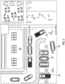
- a vehicle lane 32 can be identified. If the sensors observe consistently slow moving objects in a certain area, a pedestrian crosswalk 34 can be identified. If the sensors observe large objects driving both forwards and backwards in a certain area, parking spaces 36 can be identified as shown in Figure 3 .
- the system 26 continues to compile the sensor data over time. This allows the system 26 to identify any changes in the patterns such that the intersection map can be adjusted as needed. This new or adjusted map configuration can be broadcast over the V2X communication system 30. Thus, real-time data is being used for each unique intersection. This provides improved accuracy and can account for any anomalies that may occur. For example, a delivery truck may be doubled parked in the street for a delivery e.g. parked in a vehicle lane and not in a parking space, such that cargo can be loaded or unloaded. A vehicle 38 that may be turning onto that street cannot "see" that the truck is blocking a lane. The system 26 uses the data from the sensors 24 to identify that there is an object that needs to be avoided and broadcasts this information via V2X.
- the system 26 is also configured to prioritize objects within the learned map of the intersection such that the anomalies within the intersection can be identified. For example, the doubled parked delivery van would be given a higher priority over other incoming data, such as regular traffic flow, for example. The system 26 would be able to quickly identify this traffic blocking object such that this information could then be broadcasted via the communication system 30.
- This allows vehicles 38 such as autonomous vehicles for example, to have real time information about anomalies in the intersection and streets surrounding the intersection prior to the vehicle 38 actually entering the intersection. This could also be useful for large parking lots where vehicles 38 driving in the wrong direction or driving across multiple parking spaces can be easily identified using the data from the sensors 24.
- the system 26 can be a separate system or can be incorporated as part of the control system 22 for the traffic lights 20.
- the system(s) 26 can include one or more controllers comprising a processor, memory, and one or more input and/or output (I/O) device interface(s) that are communicatively coupled via a local interface.
- the local interface can include, for example but not limited to, one or more buses and/or other wired or wireless connections.
- the local interface may have additional elements, which are omitted for simplicity, such as controllers, buffers (caches), drivers, repeaters, and receivers to enable communications. Further, the local interface may include address, control, and/or data connections to enable appropriate communications among the aforementioned components.
- the controller may be a hardware device for executing software, particularly software stored in memory.
- the controller can be a custom made or commercially available processor, a central processing unit (CPU), an auxiliary processor among several processors associated with the computing device, a semiconductor based microprocessor (in the form of a microchip or chip set), or generally any device for executing software instructions.
- the memory can include any one or combination of volatile memory elements (e.g., random access memory (RAM, such as DRAM, SRAM, SDRAM, VRAM, etc.)) and/or nonvolatile memory elements (e.g., ROM, hard drive, tape, CD-ROM, etc.).
- volatile memory elements e.g., random access memory (RAM, such as DRAM, SRAM, SDRAM, VRAM, etc.)
- nonvolatile memory elements e.g., ROM, hard drive, tape, CD-ROM, etc.
- the memory may incorporate electronic, magnetic, optical, and/or other types of storage media.
- the memory can also have a distributed architecture, where various components are situated remotely from one another, but can be accessed by the processor.
- the software in the memory may include one or more separate programs, each of which includes an ordered listing of executable instructions for implementing logical functions.
- a system component embodied as software may also be construed as a source program, executable program (object code), script, or any other entity comprising a set of instructions to be performed.
- the program is translated via a compiler, assembler, interpreter, or the like, which may or may not be included within the memory.
- the Input/Output devices that may be coupled to system I/O Interface(s) may include input devices, for example but not limited to, a keyboard, mouse, scanner, microphone, camera, proximity device, etc. Further, the Input/Output devices may also include output devices, for example but not limited to, a printer, display, etc. Finally, the Input/Output devices may further include devices that communicate both as inputs and outputs, for instance but not limited to, a modulator/demodulator (modem; for accessing another device, system, or network), a radio frequency (RF) or other transceiver, a telephonic interface, a bridge, a router, etc.
- modem for accessing another device, system, or network
- RF radio frequency
- the controller can be configured to execute software stored within the memory, to communicate data to and from the memory, and to generally control operations of the computing device pursuant to the software.
- Software in memory, in whole or in part, is read by the processor, perhaps buffered within the processor, and then executed.
- the system 26 uses sensors 24 to observe traffic participant behavior patterns over time to create an accurate map of the intersection.
- the subject invention uses an algorithm to create the learned map of the intersection over time by identifying and categorizing the patterns that are seen by the sensors 24.
- One of ordinary skill in the art would be able configure a system controller with such an algorithm. This is beneficial over other concepts that require that the intersection be programmed with all the data upfront identifying where legal markings are on the street.
- the advantage with the subject invention is that the system 26 learns the behavior of the intersection rather than being pre-programmed with the intersection information that may be inaccurate. Additionally, as every intersection is different, there is no need to manually specify where any unique or interesting points are in the intersection, the system 26 identifies them on its own by observing the repeated patterns over time.
Landscapes
- Physics & Mathematics (AREA)
- General Physics & Mathematics (AREA)
- Engineering & Computer Science (AREA)
- Chemical & Material Sciences (AREA)
- Analytical Chemistry (AREA)
- Radar, Positioning & Navigation (AREA)
- Remote Sensing (AREA)
- Multimedia (AREA)
- Theoretical Computer Science (AREA)
- Automation & Control Theory (AREA)
- Traffic Control Systems (AREA)
Description
- The subject invention provides a system and method for identifying movement patterns in an intersection and creating a map of the intersection based on learned movement patterns.
- Environmental sensor systems provide data to autonomous vehicles such that the vehicles can follow lanes, avoid collisions, re-route around traffic, etc. These systems can also communicate data to driver-operated vehicles to provide updates regarding weather, traffic, road conditions, emergency warnings, etc. The sensor systems include various types of sensors that are mounted to infrastructure (traffic lights, signs, parking meters, etc.) near intersections, along roads, and on buildings. The sensor systems are used to recognize lane and crosswalk boundaries, and can also be used to determine distances between vehicles and/or other objects that are stationary or moving in or along the road.
- Road intersections are one of the more complicated areas to address. In urban areas, for example, in addition to having intersecting roads for traffic flow, there are crosswalks, pedestrians, bike lanes, parking areas, etc. that each have to be mapped with precision such that autonomous vehicles can successfully navigate the intersection. Each intersection is unique and has interesting points that need to be identified, e.g. traffic light or sign placement, road curvature, parking patterns, etc. All of this information must be preprogrammed into a control system such that there is an accurate map of the intersection. This is expensive and labor intensive.
-
US2015325119A1 already shows a device for site-specific traffic analysis, comprising at least one radar sensor monitoring a traffic space. An evaluation unit is configured to ascertain object trajectories from chronological sequences of object positions of respective objects detected by the radar sensor and moving in the traffic space, identify the location of at least one traffic path based on a concentration of object trajectories, and assign further detected objects to the at least one traffic path whose location has been identified. The device identifies the location and the type of the at least one traffic path based on a concentration of object trajectories. The evaluation unit is configured to carry out a summarizing evaluation of data for multiple objects assigned to the same traffic path for the determination of at least one traffic parameter selected from an average speed, a minimal speed, a minimal distance between the objects, an average distance between the objects, a maximal distance between the objects, a traffic flow and a traffic density. - In IET Intelligent Transport Systems / et al. described a trajectory analysis for parking lot vacancy detection system, which analyses the trajectory of objects in parking areas, but bases on a model of the parking space, which is detected by a camera. Basing on this model of the parking space the trajectory is analyzed to define the parking events and the degree of occupancy of the parking space.
- According to the invention, a method includes mounting one or more ambient or environmental sensors to an infrastructure component, the sensor being configured for tracking location and movement information in an intersection adjacent to the infrastructure component, identifying movement patterns based on sensor data from the sensors in the intersection adjacent to the infrastructure component, wherein one of the movement patterns comprises objects (38) repeatedly moving back and forth in a common area at a speed that is less than a predetermined speed, and creating a map of the intersection based on the movement patterns, wherein the map of the intersection comprises a parking space identified by the movement patterns of objects repeatedly moving back and forth in a common area at a speed that is less than a predetermined speed.
- In an embodiment according to the previous embodiment, the method includes mounting the sensors to a traffic light.
- In another embodiment according to any of the previous embodiments, the method includes prioritizing objects within the map of the intersection, identifying anomalies within the intersection, and broadcasting information regarding the anomalies over a communication system.
- In another embodiment according to any of the previous embodiments, the method includes communicating sensor data from the one or more ambient or environmental sensors to a controller configured with an algorithm to create a learned map of the intersection over time by identifying and categorizing movement patterns that are sensed by the one or more ambient or environmental sensors.
- In another embodiment according to any of the previous embodiments, the method includes providing a wireless communication system that receives the learned map of the intersection from the controller and broadcasts the learned map to other vehicles, infrastructure devices, and/or pedestrians adjacent to the intersection.
- In another embodiment according to any of the previous embodiments, the one or more ambient or environmental sensors comprises one or more of a motion sensor, optical camera sensor, radar sensor, lidar sensor, laser sensor and/or ultrasonic sensor.
- In another embodiment according to any of the previous embodiments, the method includes mounting the sensors to traffic lights, signs, buildings, and/or street lights.
- According to the invention, a system includes a plurality of ambient or environmental sensors configured to be mounted to at least one infrastructure component, the plurality of ambient or environmental sensors being configured for tracking location and movement information in an intersection adjacent to the at least one infrastructure component, and a controller configured to receive sensor data and use the sensor data to identify movement patterns in the intersection adjacent to the infrastructure component, wherein one of the movement patterns comprises objects (38) repeatedly moving back and forth in a common area at a speed that is less than a predetermined speed, and configured to map the intersection based on the movement patterns, wherein the map comprises a parking space identified by the movement pattern of objects repeatedly moving back and forth in the common area at the speed that is less than the predetermined speed.
- In another embodiment according to the previous embodiment, the controller is configured to identify a vehicle lane when one of the movement patterns comprises identifying objects repeatedly moving through a same area at a speed that is greater than a predetermined speed.
- In another embodiment according to any of the previous embodiments, the controller is configured to identify a crosswalk when one of the movement patterns comprises identifying objects repeatedly moving through a same area at a speed that is less than a predetermined speed.
- In another embodiment according to any of the previous embodiment, the controller is configured to identify a parking space when one of the movement patterns comprises identifying objects repeatedly moving back and forth in a common area at a speed that is less than a predetermined speed.
- In another embodiment according to any of the previous embodiments, the plurality of sensors are mounted to one or more traffic lights or signs.
- In another embodiment according to any of the previous embodiments, the controller is configured to prioritize objects within the map of the intersection generated by the controller based on the sensor data, identify anomalies within the intersection, and broadcast information regarding the anomalies over a communication system.
- In another embodiment according to any of the previous embodiments, the controller is configured with an algorithm to create the learned map of the intersection over time by identifying and categorizing movement patterns that are sensed by the plurality of ambient or environmental sensors.
- In another embodiment according to any of the previous embodiments, the system includes a wireless communication system that receives the learned map from the controller and broadcasts the learned map to other vehicles, infrastructure devices, and/or pedestrians adjacent to the intersection.
- In another embodiment according to any of the previous embodiments, the plurality of ambient or environmental sensors comprises one or more of a motion sensor, optical camera sensor, radar sensor, lidar sensor, laser sensor and/or ultrasonic sensor.
- In another embodiment according to any of the previous embodiments, the sensors are mounted to traffic lights, signs, buildings, and/or street lights.
- The disclosure can be further understood by reference to the following detailed description when considered in connection with the accompanying drawings wherein:
-
Figure 1 is a view of an intersection incorporating a system according to the invention. -
Figure 2 is an example of another intersection incorporating a system according to the invention. -
Figure 3 is an example of a parking area incorporating a system according to the invention. - The embodiments, examples and alternatives of the preceding paragraphs, the claims, or the following description and drawings, including any of their various aspects or respective individual features, may be taken independently or in any combination. Features described in connection with one embodiment are applicable to all embodiments, unless such features are incompatible.
- The subject invention provides a system and method that includes mounting one or more sensors to an infrastructure component, identifying movement patterns in an intersection adjacent to the infrastructure component, and creating a map of the intersection based on the movement patterns. Examples of movement patterns can include any of the following. A vehicle lane can be identified when one of the movement patterns comprises identifying objects repeatedly moving through a same area at a speed that is greater than a predetermined speed, e.g. a faster speed that would be associated with a vehicle. A crosswalk can be identified when one of the movement patterns comprises identifying objects repeatedly moving through a same area at a speed that is less than a predetermined speed, e.g. a slow speed associated with walking. According to the invention, a parking space can be identified when one of the movement patterns comprises identifying objects repeatedly moving back and forth in a common area at a speed that is less than a predetermined speed, e.g. forward and reverse maneuvering in a small defined area.
-
Figures 1 and2 show an intersection of afirst road 10 with asecond road 12. Atraffic light system 14 is positioned at a corner between the first 10 and second 12 roads or in a central location between theroads traffic light system 14 includes at least onemain pole 16 that extends upwardly from the ground and supports one or more secondary poles or traffic arms 18. Each traffic arm 18 includes one ormore traffic lights 20. Themain pole 16 itself may include the traffic light without requiring traffic arms. Or, themain pole 16 may also includetraffic lights 20 in addition to those on the traffic arms 18. Optionally, thetraffic lights 20 can be suspended on a cable or wire extending across the intersection. Acontrol system 22 controls operation of thetraffic lights 20 such thatvehicles 38 can move efficiently through the intersection without colliding with each other. - Ambient or
environmental sensors 24 are mounted to infrastructure, such asbuildings 28,signs 40, street lights, thepole 16, arms 18, orlights 20. Asystem 26 uses data from thesensors 24, which track movement patterns over time, to learn and create a map of the intersection as a fixed environment. Thus, thesensors 24 are used to monitor movement patterns and speed to identify the location of fixed structures or areas, e.g. lights, hydrants, signs, lanes, crosswalks, parking spaces, etc., such that moving objects (pedestrians 42, bikers,vehicles 38, etc.) can have a frame of reference. This is important for Advanced Driver Assistance Systems (ADAS) and for autonomous vehicles. In one example, thesystem 26 uses ambient/environmental sensors 24 that comprise one or more of the following: motion sensor, optical camera sensor, radar sensor, lidar sensor, laser sensor and/or ultrasonic sensor. Thesesensors 24 capture location and movement information frompedestrians 42 andvehicles 38 in relation to other vehicles, pedestrians, or infrastructure to create a map of the intersection. Thesensors 24 track this location and movement information over time and thesystem 26 is configured to compile this information to recognize patterns of location/movement. These patterns can be used to identify lane boundaries, crosswalk boundaries, etc. with precise accuracy based on the sensors that are actually at the intersection. - This information can be used to create a map of the intersection and this can then be broadcast over a
wireless communication system 30. One example of a communication system is referred to as "vehicle-to-everything (V2X)" communication, and includes the passing of information from avehicle 38 to any entity that may affect thevehicle 38, and vice versa. It is a vehicular communication system that incorporates other more specific types of communication such as V2I (vehicle-to-infrastructure), V2N (vehicle-to-network), V2V (vehicle-to-vehicle), V2P (vehicle-to-pedestrian), V2D (vehicle-to-device), and V2G (vehicle-to-grid). This type of communication improves road safety and traffic efficiency, as well as providing energy savings. - The
communication system 30 wirelessly communicates via the V2X communication systems to exchange information with surroundingvehicles 38 or infrastructure devices. The V2X messages sent by thevehicles 38 usually comprise at least an absolute position, an absolute speed, and a piece of information about the direction of travel. The V2X messages sent by thesystem 26 usually comprise the map of the intersection that identifies lane locations, crosswalk locations, parking space locations, etc. For the V2X communication system to send and/or receive messages and/or information, the system can use one or more of the following connection classes: WLAN connection, e.g. based on IEEE 802.11, ISM (Industrial, Scientific, Medical Band) connection, Bluetooth® connection, ZigBee connection, UWB (ultrawide band) connection, WiMax® (Worldwide Interoperability for Microwave Access) connection, LTE-V2X, Dedicated Short Range Communications (DSRC), infrared connection, mobile radio connection, and/or radar-based communication. - It is important that the
environmental sensors 24 that are at the actual intersection location provide the data that is used to create the intersection map, such that the map is based on real and observed object behavior. As such, it is not required to calibrate or create a map of an intersection that is pre-programmed into thesystem 26. Instead, thesystem 26 itself learns the actual movement of the traffic participants (vehicles 38,pedestrians 42, bikers, etc.) within the intersection to provide an accurate representation of the intersection. This avoids any potential of inaccurate data being used to create a map ahead of time. The subject invention uses an algorithm to create a learned map of the intersection over time by observing patterns that are seen by thesensors 24. For example, if a sensor sees objects moving quickly through the same area over and over again, avehicle lane 32 can be identified. If the sensors observe consistently slow moving objects in a certain area, apedestrian crosswalk 34 can be identified. If the sensors observe large objects driving both forwards and backwards in a certain area, parking spaces 36 can be identified as shown inFigure 3 . - The
system 26 continues to compile the sensor data over time. This allows thesystem 26 to identify any changes in the patterns such that the intersection map can be adjusted as needed. This new or adjusted map configuration can be broadcast over theV2X communication system 30. Thus, real-time data is being used for each unique intersection. This provides improved accuracy and can account for any anomalies that may occur. For example, a delivery truck may be doubled parked in the street for a delivery e.g. parked in a vehicle lane and not in a parking space, such that cargo can be loaded or unloaded. Avehicle 38 that may be turning onto that street cannot "see" that the truck is blocking a lane. Thesystem 26 uses the data from thesensors 24 to identify that there is an object that needs to be avoided and broadcasts this information via V2X. - The
system 26 is also configured to prioritize objects within the learned map of the intersection such that the anomalies within the intersection can be identified. For example, the doubled parked delivery van would be given a higher priority over other incoming data, such as regular traffic flow, for example. Thesystem 26 would be able to quickly identify this traffic blocking object such that this information could then be broadcasted via thecommunication system 30. This allowsvehicles 38 such as autonomous vehicles for example, to have real time information about anomalies in the intersection and streets surrounding the intersection prior to thevehicle 38 actually entering the intersection. This could also be useful for large parking lots wherevehicles 38 driving in the wrong direction or driving across multiple parking spaces can be easily identified using the data from thesensors 24. - The
system 26 can be a separate system or can be incorporated as part of thecontrol system 22 for thetraffic lights 20. The system(s) 26 can include one or more controllers comprising a processor, memory, and one or more input and/or output (I/O) device interface(s) that are communicatively coupled via a local interface. The local interface can include, for example but not limited to, one or more buses and/or other wired or wireless connections. The local interface may have additional elements, which are omitted for simplicity, such as controllers, buffers (caches), drivers, repeaters, and receivers to enable communications. Further, the local interface may include address, control, and/or data connections to enable appropriate communications among the aforementioned components. - The controller may be a hardware device for executing software, particularly software stored in memory. The controller can be a custom made or commercially available processor, a central processing unit (CPU), an auxiliary processor among several processors associated with the computing device, a semiconductor based microprocessor (in the form of a microchip or chip set), or generally any device for executing software instructions.
- The memory can include any one or combination of volatile memory elements (e.g., random access memory (RAM, such as DRAM, SRAM, SDRAM, VRAM, etc.)) and/or nonvolatile memory elements (e.g., ROM, hard drive, tape, CD-ROM, etc.). Moreover, the memory may incorporate electronic, magnetic, optical, and/or other types of storage media. Note that the memory can also have a distributed architecture, where various components are situated remotely from one another, but can be accessed by the processor.
- The software in the memory may include one or more separate programs, each of which includes an ordered listing of executable instructions for implementing logical functions. A system component embodied as software may also be construed as a source program, executable program (object code), script, or any other entity comprising a set of instructions to be performed. When constructed as a source program, the program is translated via a compiler, assembler, interpreter, or the like, which may or may not be included within the memory.
- The Input/Output devices that may be coupled to system I/O Interface(s) may include input devices, for example but not limited to, a keyboard, mouse, scanner, microphone, camera, proximity device, etc. Further, the Input/Output devices may also include output devices, for example but not limited to, a printer, display, etc. Finally, the Input/Output devices may further include devices that communicate both as inputs and outputs, for instance but not limited to, a modulator/demodulator (modem; for accessing another device, system, or network), a radio frequency (RF) or other transceiver, a telephonic interface, a bridge, a router, etc.
- The controller can be configured to execute software stored within the memory, to communicate data to and from the memory, and to generally control operations of the computing device pursuant to the software. Software in memory, in whole or in part, is read by the processor, perhaps buffered within the processor, and then executed.
- As discussed above, the
system 26 usessensors 24 to observe traffic participant behavior patterns over time to create an accurate map of the intersection. The subject invention uses an algorithm to create the learned map of the intersection over time by identifying and categorizing the patterns that are seen by thesensors 24. One of ordinary skill in the art would be able configure a system controller with such an algorithm. This is beneficial over other concepts that require that the intersection be programmed with all the data upfront identifying where legal markings are on the street. The advantage with the subject invention is that thesystem 26 learns the behavior of the intersection rather than being pre-programmed with the intersection information that may be inaccurate. Additionally, as every intersection is different, there is no need to manually specify where any unique or interesting points are in the intersection, thesystem 26 identifies them on its own by observing the repeated patterns over time. - It should also be understood that although a particular component arrangement is disclosed in the illustrated embodiment, other arrangements will benefit herefrom.
- Although the different examples have specific components shown in the illustrations, embodiments of this invention are not limited to those particular combinations. It is possible to use some of the components or features from one of the examples in combination with features or components from another one of the examples.
- Although an example embodiment has been disclosed, a worker of ordinary skill in this art would recognize that certain modifications would come within the scope of the claims. For that reason, the following claims should be studied to determine their true scope and content.
Claims (13)
- A method comprising:(a) mounting one or more ambient or environmental sensors (24) to an infrastructure component (16, 18, 20, 28, 40), the one or more ambient or environmental sensor (24) being configured for tracking location and movement information in an intersection (10, 12) adjacent to the infrastructure component (16, 18, 20, 28, 40);(b) identifying movement patterns based on sensor data from the one or more ambient or environmental sensors (24) in the intersection (10, 12) adjacent to the infrastructure component (16, 18, 20, 28, 40), wherein one of the movement patterns comprises objects (38) repeatedly moving back and forth in a common area at a speed that is less than a predetermined speed; and(c) creating a map of the intersection (10, 12) based on the movement patterns, wherein the map of the intersection comprises a parking space (36) identified by the movement patterns of objects (38) repeatedly moving back and forth in the common area at a speed that is less than a predetermined speed.
- The method according to claim 1, wherein step (a) includes mounting the sensors (24) to a traffic light (20).
- The method according to claim 1, including prioritizing objects within the map of the intersection (10, 12), identifying anomalies within the intersection (10, 12), and broadcasting information regarding the anomalies over a communication system.
- The method according to claim 1, including communicating sensor data from the one or more ambient or environmental sensors (24) to a controller (26) configured with an algorithm to create a learned map of the intersection over time by identifying and categorizing movement patterns that are sensed by the one or more ambient or environmental sensors.
- The method according to claim 4, providing a wireless communication system (30) that receives the learned map of the intersection from the controller and broadcasts the learned map to other vehicles, infrastructure devices, and/or pedestrians adjacent to the intersection (10, 12).
- The method according to claim 1, wherein the one or more ambient or environmental sensors (24) comprises one or more of a motion sensor, optical camera sensor, radar sensor, lidar sensor, laser sensor and/or ultrasonic sensor.
- The method according to claim 6, including mounting the sensors to traffic lights (20), signs (40), buildings (28), and/or street lights (16, 18).
- A system comprising:a plurality of ambient or environmental sensors (24) configured to be mounted to at least one infrastructure component (16, 18 ,20, 28, 40), the plurality of ambient or environmental sensors (24) being configured for tracking location and movement information in an intersection (10, 12) adjacent to the at least one infrastructure component (16, 18, 20, 28, 40); anda controller (26) configured to receive sensor data and use the sensor data to identify movement patterns in the intersection (10, 12) adjacent to the infrastructure component, wherein one of the movement patterns comprises objects (38) repeatedly moving back and forth in a common area at a speed that is less than a predetermined speed, and configured to map the intersection (10, 12) based on the movement patterns, wherein the map comprises a parking space identified by the movement pattern of objects (38) repeatedly moving back and forth in the common area at the speed that is less than the predetermined speed.
- The system according to claim 8, wherein the controller (26) is configured toprioritize objects within the map of the intersection (10, 12) generated by the controller (26) based on the sensor data,identify anomalies within the intersection (10, 12), andbroadcast information regarding the anomalies over a communication system.
- The system according to claim 8, wherein the controller (26) is configured with an algorithm to create the learned map of the intersection (10, 12) over time by identifying and categorizing the movement patterns that are sensed by the plurality of ambient or environmental sensors (24).
- The system according to claim 10, including a wireless communication system that receives the learned map from the controller and broadcasts the learned map to other vehicles, infrastructure devices, and/or pedestrians adjacent to the intersection (10, 12).
- The system according to claim 8, wherein the plurality of ambient or environmental sensors (24) comprises one or more of a motion sensor, optical camera sensor, radar sensor, lidar sensor, laser sensor and/or ultrasonic sensor.
- The system according to claim 8 or 12, wherein the sensors are mounted to one or more traffic lights (20), signs (40), buildings (28), and/or street lights (16, 18).
Applications Claiming Priority (3)
| Application Number | Priority Date | Filing Date | Title |
|---|---|---|---|
| US201862785327P | 2018-12-27 | 2018-12-27 | |
| US16/579,970 US11217090B2 (en) | 2018-12-27 | 2019-09-24 | Learned intersection map from long term sensor data |
| PCT/US2019/066140 WO2020139581A1 (en) | 2018-12-27 | 2019-12-13 | Learned intersection map from long term sensor data |
Publications (2)
| Publication Number | Publication Date |
|---|---|
| EP3903068A1 EP3903068A1 (en) | 2021-11-03 |
| EP3903068B1 true EP3903068B1 (en) | 2023-11-15 |
Family
ID=71122122
Family Applications (1)
| Application Number | Title | Priority Date | Filing Date |
|---|---|---|---|
| EP19842911.0A Active EP3903068B1 (en) | 2018-12-27 | 2019-12-13 | Learned intersection map from long term sensor data |
Country Status (4)
| Country | Link |
|---|---|
| US (1) | US11217090B2 (en) |
| EP (1) | EP3903068B1 (en) |
| CN (1) | CN113196010B (en) |
| WO (1) | WO2020139581A1 (en) |
Families Citing this family (3)
| Publication number | Priority date | Publication date | Assignee | Title |
|---|---|---|---|---|
| US11217090B2 (en) * | 2018-12-27 | 2022-01-04 | Continental Automotive Systems, Inc. | Learned intersection map from long term sensor data |
| US20240386795A1 (en) * | 2023-05-19 | 2024-11-21 | Qualcomm Incorporated | Traffic camera-based determination of traffic signal-to-lane association for automated vehicle operation |
| US20250353488A1 (en) * | 2024-05-17 | 2025-11-20 | Zoox, Inc. | Dynamic parking location determining management |
Family Cites Families (30)
| Publication number | Priority date | Publication date | Assignee | Title |
|---|---|---|---|---|
| CN101042802A (en) * | 2006-03-23 | 2007-09-26 | 安捷伦科技有限公司 | Traffic information sensor and method and system for traffic information detecting |
| JP5064870B2 (en) * | 2007-04-17 | 2012-10-31 | 株式会社日立製作所 | Digital road map generation method and map generation system |
| EP2308035A4 (en) * | 2008-06-13 | 2011-10-19 | Tmt Services And Supplies Pty Ltd | Traffic control system and method |
| FR2963827B1 (en) * | 2010-08-13 | 2012-08-17 | Continental Automotive France | METHOD AND DEVICE FOR ASSISTING THE DRIVING AND ANTICIPATION OF A ROAD TRACK |
| KR20130005176A (en) * | 2011-07-05 | 2013-01-15 | 현대자동차주식회사 | Device for sensing rear or side vehicles |
| US8855904B1 (en) * | 2012-10-10 | 2014-10-07 | Google Inc. | Use of position logs of vehicles to determine presence and behaviors of traffic controls |
| US20140307087A1 (en) * | 2013-04-10 | 2014-10-16 | Xerox Corporation | Methods and systems for preventing traffic accidents |
| JP6397827B2 (en) * | 2013-12-27 | 2018-09-26 | 株式会社シーズ・ラボ | Map data update device |
| DE102014208524B4 (en) | 2014-05-07 | 2025-10-30 | Robert Bosch Gmbh | Location-specific traffic analysis with traffic path detection |
| US9349288B2 (en) * | 2014-07-28 | 2016-05-24 | Econolite Group, Inc. | Self-configuring traffic signal controller |
| DE102014220263A1 (en) * | 2014-10-07 | 2016-04-07 | Conti Temic Microelectronic Gmbh | Method and system for supporting a parking operation of a motor vehicle |
| US10533863B2 (en) * | 2014-10-10 | 2020-01-14 | Here Global B.V. | Apparatus and associated methods for use in lane-level mapping of road intersections |
| US10803742B2 (en) * | 2015-09-08 | 2020-10-13 | Ofer Hofman | Method for traffic control |
| CN106228835B (en) * | 2016-07-18 | 2019-04-26 | 北京精英智通科技股份有限公司 | A kind of parking stall Parking judgment method and system |
| CN106441319B (en) * | 2016-09-23 | 2019-07-16 | 中国科学院合肥物质科学研究院 | A system and method for generating a lane-level navigation map of an unmanned vehicle |
| EP3545376A4 (en) * | 2016-11-22 | 2020-07-01 | Amazon Technologies Inc. | METHOD FOR AUTONOMOUS NAVIGATION THROUGH UNCONTROLLED AND CONTROLLED INtersections |
| CN108205925B (en) * | 2016-12-17 | 2020-12-11 | 杭州海康威视数字技术股份有限公司 | A method and device for obtaining parking space status |
| CN107038411A (en) * | 2017-02-26 | 2017-08-11 | 北京市交通运行监测调度中心 | A kind of Roadside Parking behavior precise recognition method based on vehicle movement track in video |
| DE102017204180B3 (en) * | 2017-03-14 | 2018-08-02 | Audi Ag | Method for determining and / or managing a parking ticket |
| WO2018215833A1 (en) * | 2017-05-23 | 2018-11-29 | 1.21 Gigawatts Ltd. | Traffic monitoring and management systems and methods |
| KR101921429B1 (en) * | 2017-11-10 | 2018-11-22 | 한국항공우주연구원 | Method and system for making precise map |
| KR102464607B1 (en) * | 2017-12-27 | 2022-11-08 | 현대자동차주식회사 | Vehicle and controlling method thereof |
| US11042163B2 (en) * | 2018-01-07 | 2021-06-22 | Nvidia Corporation | Guiding vehicles through vehicle maneuvers using machine learning models |
| JP7119653B2 (en) * | 2018-07-02 | 2022-08-17 | 株式会社デンソー | vehicle controller |
| KR102132899B1 (en) * | 2018-10-08 | 2020-07-21 | 주식회사 만도 | Route Generation Apparatus at Crossroad, Method and Apparatus for Controlling Vehicle at Crossroad |
| US11217090B2 (en) * | 2018-12-27 | 2022-01-04 | Continental Automotive Systems, Inc. | Learned intersection map from long term sensor data |
| US11137766B2 (en) * | 2019-03-07 | 2021-10-05 | Zoox, Inc. | State machine for traversing junctions |
| US11136023B2 (en) * | 2019-05-07 | 2021-10-05 | Baidu Usa Llc | Method for determining exiting intersection of moving objects for autonomous driving vehicles |
| KR102861723B1 (en) * | 2019-08-26 | 2025-09-18 | 엘지전자 주식회사 | Method for releasing security by using spatial information related to robot and robot thereof |
| US11420630B2 (en) * | 2019-10-24 | 2022-08-23 | Zoox, Inc. | Trajectory modifications based on a collision zone |
-
2019
- 2019-09-24 US US16/579,970 patent/US11217090B2/en active Active
- 2019-12-13 EP EP19842911.0A patent/EP3903068B1/en active Active
- 2019-12-13 WO PCT/US2019/066140 patent/WO2020139581A1/en not_active Ceased
- 2019-12-13 CN CN201980086185.3A patent/CN113196010B/en active Active
Also Published As
| Publication number | Publication date |
|---|---|
| US20200211371A1 (en) | 2020-07-02 |
| CN113196010A (en) | 2021-07-30 |
| CN113196010B (en) | 2024-10-18 |
| US11217090B2 (en) | 2022-01-04 |
| WO2020139581A1 (en) | 2020-07-02 |
| EP3903068A1 (en) | 2021-11-03 |
Similar Documents
| Publication | Publication Date | Title |
|---|---|---|
| US11442450B2 (en) | Method for determining passable area in planning a path of autonomous driving vehicles | |
| US11462022B2 (en) | Traffic signal analysis system | |
| CN114750783B (en) | Modeling road user reactions to operate autonomous vehicles in the presence of occlusion | |
| US11685398B2 (en) | Lane based routing system for autonomous driving vehicles | |
| JP6840240B2 (en) | Dynamic route determination for autonomous vehicles | |
| KR102127798B1 (en) | Method and vehicle communication system for determining driving intention for vehicle | |
| CN107949875B (en) | Method and system for determining traffic participants with interaction possibilities | |
| US11210937B2 (en) | Method for un-signalized intersection traffic flow management | |
| US12017681B2 (en) | Obstacle prediction system for autonomous driving vehicles | |
| US11662730B2 (en) | Hierarchical path decision system for planning a path for an autonomous driving vehicle | |
| US20210300427A1 (en) | Group and combine obstacles for autonomous driving vehicles | |
| US12055407B2 (en) | Mixed regular and open-space trajectory planning method for autonomous driving vehicle | |
| US11491976B2 (en) | Collision warning system for safety operators of autonomous vehicles | |
| US11880201B2 (en) | Fastest lane determination algorithm under traffic jam | |
| EP4145420A1 (en) | Hierarchical processing of traffic signal face states | |
| US20200211379A1 (en) | Roundabout assist | |
| CN115292435A (en) | High-precision map updating method and device, electronic equipment and storage medium | |
| EP3903068B1 (en) | Learned intersection map from long term sensor data | |
| JP2025510690A (en) | Intersection-Based Off-Board Vehicle Path Generation | |
| CN112985435A (en) | Method and system for operating an autonomously driven vehicle | |
| US20230202469A1 (en) | Drive with caution under uncertainty for an autonomous driving vehicle | |
| JP2025510691A (en) | Collision warning based on intersection information in map messages | |
| CN112712718A (en) | Vehicle, fleet management and traffic signal light interaction architecture design via V2X | |
| US20240005066A1 (en) | Decoupled prediction evaluation | |
| US11242057B2 (en) | Method for optimizing three-point turn of autonomous driving vehicles |
Legal Events
| Date | Code | Title | Description |
|---|---|---|---|
| STAA | Information on the status of an ep patent application or granted ep patent |
Free format text: STATUS: UNKNOWN |
|
| STAA | Information on the status of an ep patent application or granted ep patent |
Free format text: STATUS: THE INTERNATIONAL PUBLICATION HAS BEEN MADE |
|
| PUAI | Public reference made under article 153(3) epc to a published international application that has entered the european phase |
Free format text: ORIGINAL CODE: 0009012 |
|
| STAA | Information on the status of an ep patent application or granted ep patent |
Free format text: STATUS: REQUEST FOR EXAMINATION WAS MADE |
|
| 17P | Request for examination filed |
Effective date: 20210727 |
|
| AK | Designated contracting states |
Kind code of ref document: A1 Designated state(s): AL AT BE BG CH CY CZ DE DK EE ES FI FR GB GR HR HU IE IS IT LI LT LU LV MC MK MT NL NO PL PT RO RS SE SI SK SM TR |
|
| DAV | Request for validation of the european patent (deleted) | ||
| DAX | Request for extension of the european patent (deleted) | ||
| STAA | Information on the status of an ep patent application or granted ep patent |
Free format text: STATUS: EXAMINATION IS IN PROGRESS |
|
| 17Q | First examination report despatched |
Effective date: 20220720 |
|
| RIC1 | Information provided on ipc code assigned before grant |
Ipc: G08G 1/04 20060101ALI20230516BHEP Ipc: G06V 20/54 20220101ALI20230516BHEP Ipc: G08G 1/01 20060101ALI20230516BHEP Ipc: G01C 21/30 20060101AFI20230516BHEP |
|
| GRAP | Despatch of communication of intention to grant a patent |
Free format text: ORIGINAL CODE: EPIDOSNIGR1 |
|
| STAA | Information on the status of an ep patent application or granted ep patent |
Free format text: STATUS: GRANT OF PATENT IS INTENDED |
|
| INTG | Intention to grant announced |
Effective date: 20230712 |
|
| GRAS | Grant fee paid |
Free format text: ORIGINAL CODE: EPIDOSNIGR3 |
|
| GRAA | (expected) grant |
Free format text: ORIGINAL CODE: 0009210 |
|
| STAA | Information on the status of an ep patent application or granted ep patent |
Free format text: STATUS: THE PATENT HAS BEEN GRANTED |
|
| AK | Designated contracting states |
Kind code of ref document: B1 Designated state(s): AL AT BE BG CH CY CZ DE DK EE ES FI FR GB GR HR HU IE IS IT LI LT LU LV MC MK MT NL NO PL PT RO RS SE SI SK SM TR |
|
| REG | Reference to a national code |
Ref country code: CH Ref legal event code: EP Ref country code: GB Ref legal event code: FG4D |
|
| REG | Reference to a national code |
Ref country code: DE Ref legal event code: R096 Ref document number: 602019041634 Country of ref document: DE |
|
| REG | Reference to a national code |
Ref country code: IE Ref legal event code: FG4D |
|
| REG | Reference to a national code |
Ref country code: SE Ref legal event code: TRGR |
|
| REG | Reference to a national code |
Ref country code: LT Ref legal event code: MG9D |
|
| REG | Reference to a national code |
Ref country code: NL Ref legal event code: MP Effective date: 20231115 |
|
| PG25 | Lapsed in a contracting state [announced via postgrant information from national office to epo] |
Ref country code: GR Free format text: LAPSE BECAUSE OF FAILURE TO SUBMIT A TRANSLATION OF THE DESCRIPTION OR TO PAY THE FEE WITHIN THE PRESCRIBED TIME-LIMIT Effective date: 20240216 |
|
| PG25 | Lapsed in a contracting state [announced via postgrant information from national office to epo] |
Ref country code: IS Free format text: LAPSE BECAUSE OF FAILURE TO SUBMIT A TRANSLATION OF THE DESCRIPTION OR TO PAY THE FEE WITHIN THE PRESCRIBED TIME-LIMIT Effective date: 20240315 |
|
| PG25 | Lapsed in a contracting state [announced via postgrant information from national office to epo] |
Ref country code: LT Free format text: LAPSE BECAUSE OF FAILURE TO SUBMIT A TRANSLATION OF THE DESCRIPTION OR TO PAY THE FEE WITHIN THE PRESCRIBED TIME-LIMIT Effective date: 20231115 |
|
| REG | Reference to a national code |
Ref country code: AT Ref legal event code: MK05 Ref document number: 1632150 Country of ref document: AT Kind code of ref document: T Effective date: 20231115 |
|
| PG25 | Lapsed in a contracting state [announced via postgrant information from national office to epo] |
Ref country code: NL Free format text: LAPSE BECAUSE OF FAILURE TO SUBMIT A TRANSLATION OF THE DESCRIPTION OR TO PAY THE FEE WITHIN THE PRESCRIBED TIME-LIMIT Effective date: 20231115 |
|
| PG25 | Lapsed in a contracting state [announced via postgrant information from national office to epo] |
Ref country code: AT Free format text: LAPSE BECAUSE OF FAILURE TO SUBMIT A TRANSLATION OF THE DESCRIPTION OR TO PAY THE FEE WITHIN THE PRESCRIBED TIME-LIMIT Effective date: 20231115 |
|
| PG25 | Lapsed in a contracting state [announced via postgrant information from national office to epo] |
Ref country code: ES Free format text: LAPSE BECAUSE OF FAILURE TO SUBMIT A TRANSLATION OF THE DESCRIPTION OR TO PAY THE FEE WITHIN THE PRESCRIBED TIME-LIMIT Effective date: 20231115 |
|
| PG25 | Lapsed in a contracting state [announced via postgrant information from national office to epo] |
Ref country code: NL Free format text: LAPSE BECAUSE OF FAILURE TO SUBMIT A TRANSLATION OF THE DESCRIPTION OR TO PAY THE FEE WITHIN THE PRESCRIBED TIME-LIMIT Effective date: 20231115 Ref country code: LT Free format text: LAPSE BECAUSE OF FAILURE TO SUBMIT A TRANSLATION OF THE DESCRIPTION OR TO PAY THE FEE WITHIN THE PRESCRIBED TIME-LIMIT Effective date: 20231115 Ref country code: IS Free format text: LAPSE BECAUSE OF FAILURE TO SUBMIT A TRANSLATION OF THE DESCRIPTION OR TO PAY THE FEE WITHIN THE PRESCRIBED TIME-LIMIT Effective date: 20240315 Ref country code: GR Free format text: LAPSE BECAUSE OF FAILURE TO SUBMIT A TRANSLATION OF THE DESCRIPTION OR TO PAY THE FEE WITHIN THE PRESCRIBED TIME-LIMIT Effective date: 20240216 Ref country code: ES Free format text: LAPSE BECAUSE OF FAILURE TO SUBMIT A TRANSLATION OF THE DESCRIPTION OR TO PAY THE FEE WITHIN THE PRESCRIBED TIME-LIMIT Effective date: 20231115 Ref country code: BG Free format text: LAPSE BECAUSE OF FAILURE TO SUBMIT A TRANSLATION OF THE DESCRIPTION OR TO PAY THE FEE WITHIN THE PRESCRIBED TIME-LIMIT Effective date: 20240215 Ref country code: AT Free format text: LAPSE BECAUSE OF FAILURE TO SUBMIT A TRANSLATION OF THE DESCRIPTION OR TO PAY THE FEE WITHIN THE PRESCRIBED TIME-LIMIT Effective date: 20231115 Ref country code: PT Free format text: LAPSE BECAUSE OF FAILURE TO SUBMIT A TRANSLATION OF THE DESCRIPTION OR TO PAY THE FEE WITHIN THE PRESCRIBED TIME-LIMIT Effective date: 20240315 |
|
| PG25 | Lapsed in a contracting state [announced via postgrant information from national office to epo] |
Ref country code: RS Free format text: LAPSE BECAUSE OF FAILURE TO SUBMIT A TRANSLATION OF THE DESCRIPTION OR TO PAY THE FEE WITHIN THE PRESCRIBED TIME-LIMIT Effective date: 20231115 Ref country code: PL Free format text: LAPSE BECAUSE OF FAILURE TO SUBMIT A TRANSLATION OF THE DESCRIPTION OR TO PAY THE FEE WITHIN THE PRESCRIBED TIME-LIMIT Effective date: 20231115 Ref country code: NO Free format text: LAPSE BECAUSE OF FAILURE TO SUBMIT A TRANSLATION OF THE DESCRIPTION OR TO PAY THE FEE WITHIN THE PRESCRIBED TIME-LIMIT Effective date: 20240215 Ref country code: LV Free format text: LAPSE BECAUSE OF FAILURE TO SUBMIT A TRANSLATION OF THE DESCRIPTION OR TO PAY THE FEE WITHIN THE PRESCRIBED TIME-LIMIT Effective date: 20231115 Ref country code: HR Free format text: LAPSE BECAUSE OF FAILURE TO SUBMIT A TRANSLATION OF THE DESCRIPTION OR TO PAY THE FEE WITHIN THE PRESCRIBED TIME-LIMIT Effective date: 20231115 |
|
| PG25 | Lapsed in a contracting state [announced via postgrant information from national office to epo] |
Ref country code: DK Free format text: LAPSE BECAUSE OF FAILURE TO SUBMIT A TRANSLATION OF THE DESCRIPTION OR TO PAY THE FEE WITHIN THE PRESCRIBED TIME-LIMIT Effective date: 20231115 |
|
| PG25 | Lapsed in a contracting state [announced via postgrant information from national office to epo] |
Ref country code: CZ Free format text: LAPSE BECAUSE OF FAILURE TO SUBMIT A TRANSLATION OF THE DESCRIPTION OR TO PAY THE FEE WITHIN THE PRESCRIBED TIME-LIMIT Effective date: 20231115 |
|
| PG25 | Lapsed in a contracting state [announced via postgrant information from national office to epo] |
Ref country code: SK Free format text: LAPSE BECAUSE OF FAILURE TO SUBMIT A TRANSLATION OF THE DESCRIPTION OR TO PAY THE FEE WITHIN THE PRESCRIBED TIME-LIMIT Effective date: 20231115 |
|
| PG25 | Lapsed in a contracting state [announced via postgrant information from national office to epo] |
Ref country code: SM Free format text: LAPSE BECAUSE OF FAILURE TO SUBMIT A TRANSLATION OF THE DESCRIPTION OR TO PAY THE FEE WITHIN THE PRESCRIBED TIME-LIMIT Effective date: 20231115 Ref country code: SK Free format text: LAPSE BECAUSE OF FAILURE TO SUBMIT A TRANSLATION OF THE DESCRIPTION OR TO PAY THE FEE WITHIN THE PRESCRIBED TIME-LIMIT Effective date: 20231115 Ref country code: RO Free format text: LAPSE BECAUSE OF FAILURE TO SUBMIT A TRANSLATION OF THE DESCRIPTION OR TO PAY THE FEE WITHIN THE PRESCRIBED TIME-LIMIT Effective date: 20231115 Ref country code: IT Free format text: LAPSE BECAUSE OF FAILURE TO SUBMIT A TRANSLATION OF THE DESCRIPTION OR TO PAY THE FEE WITHIN THE PRESCRIBED TIME-LIMIT Effective date: 20231115 Ref country code: EE Free format text: LAPSE BECAUSE OF FAILURE TO SUBMIT A TRANSLATION OF THE DESCRIPTION OR TO PAY THE FEE WITHIN THE PRESCRIBED TIME-LIMIT Effective date: 20231115 Ref country code: DK Free format text: LAPSE BECAUSE OF FAILURE TO SUBMIT A TRANSLATION OF THE DESCRIPTION OR TO PAY THE FEE WITHIN THE PRESCRIBED TIME-LIMIT Effective date: 20231115 Ref country code: CZ Free format text: LAPSE BECAUSE OF FAILURE TO SUBMIT A TRANSLATION OF THE DESCRIPTION OR TO PAY THE FEE WITHIN THE PRESCRIBED TIME-LIMIT Effective date: 20231115 |
|
| REG | Reference to a national code |
Ref country code: CH Ref legal event code: PL |
|
| REG | Reference to a national code |
Ref country code: DE Ref legal event code: R097 Ref document number: 602019041634 Country of ref document: DE |
|
| PG25 | Lapsed in a contracting state [announced via postgrant information from national office to epo] |
Ref country code: LU Free format text: LAPSE BECAUSE OF NON-PAYMENT OF DUE FEES Effective date: 20231213 |
|
| PG25 | Lapsed in a contracting state [announced via postgrant information from national office to epo] |
Ref country code: MC Free format text: LAPSE BECAUSE OF FAILURE TO SUBMIT A TRANSLATION OF THE DESCRIPTION OR TO PAY THE FEE WITHIN THE PRESCRIBED TIME-LIMIT Effective date: 20231115 |
|
| REG | Reference to a national code |
Ref country code: BE Ref legal event code: MM Effective date: 20231231 |
|
| PG25 | Lapsed in a contracting state [announced via postgrant information from national office to epo] |
Ref country code: MC Free format text: LAPSE BECAUSE OF FAILURE TO SUBMIT A TRANSLATION OF THE DESCRIPTION OR TO PAY THE FEE WITHIN THE PRESCRIBED TIME-LIMIT Effective date: 20231115 Ref country code: LU Free format text: LAPSE BECAUSE OF NON-PAYMENT OF DUE FEES Effective date: 20231213 |
|
| PLBE | No opposition filed within time limit |
Free format text: ORIGINAL CODE: 0009261 |
|
| STAA | Information on the status of an ep patent application or granted ep patent |
Free format text: STATUS: NO OPPOSITION FILED WITHIN TIME LIMIT |
|
| REG | Reference to a national code |
Ref country code: IE Ref legal event code: MM4A |
|
| PG25 | Lapsed in a contracting state [announced via postgrant information from national office to epo] |
Ref country code: IE Free format text: LAPSE BECAUSE OF NON-PAYMENT OF DUE FEES Effective date: 20231213 |
|
| PG25 | Lapsed in a contracting state [announced via postgrant information from national office to epo] |
Ref country code: BE Free format text: LAPSE BECAUSE OF NON-PAYMENT OF DUE FEES Effective date: 20231231 |
|
| PG25 | Lapsed in a contracting state [announced via postgrant information from national office to epo] |
Ref country code: CH Free format text: LAPSE BECAUSE OF NON-PAYMENT OF DUE FEES Effective date: 20231231 |
|
| 26N | No opposition filed |
Effective date: 20240819 |
|
| GBPC | Gb: european patent ceased through non-payment of renewal fee |
Effective date: 20240215 |
|
| PG25 | Lapsed in a contracting state [announced via postgrant information from national office to epo] |
Ref country code: SI Free format text: LAPSE BECAUSE OF FAILURE TO SUBMIT A TRANSLATION OF THE DESCRIPTION OR TO PAY THE FEE WITHIN THE PRESCRIBED TIME-LIMIT Effective date: 20231115 |
|
| PG25 | Lapsed in a contracting state [announced via postgrant information from national office to epo] |
Ref country code: SI Free format text: LAPSE BECAUSE OF FAILURE TO SUBMIT A TRANSLATION OF THE DESCRIPTION OR TO PAY THE FEE WITHIN THE PRESCRIBED TIME-LIMIT Effective date: 20231115 Ref country code: IE Free format text: LAPSE BECAUSE OF NON-PAYMENT OF DUE FEES Effective date: 20231213 Ref country code: CH Free format text: LAPSE BECAUSE OF NON-PAYMENT OF DUE FEES Effective date: 20231231 Ref country code: BE Free format text: LAPSE BECAUSE OF NON-PAYMENT OF DUE FEES Effective date: 20231231 |
|
| PG25 | Lapsed in a contracting state [announced via postgrant information from national office to epo] |
Ref country code: GB Free format text: LAPSE BECAUSE OF NON-PAYMENT OF DUE FEES Effective date: 20240215 |
|
| PG25 | Lapsed in a contracting state [announced via postgrant information from national office to epo] |
Ref country code: GB Free format text: LAPSE BECAUSE OF NON-PAYMENT OF DUE FEES Effective date: 20240215 |
|
| PG25 | Lapsed in a contracting state [announced via postgrant information from national office to epo] |
Ref country code: FI Free format text: LAPSE BECAUSE OF FAILURE TO SUBMIT A TRANSLATION OF THE DESCRIPTION OR TO PAY THE FEE WITHIN THE PRESCRIBED TIME-LIMIT Effective date: 20231115 |
|
| PG25 | Lapsed in a contracting state [announced via postgrant information from national office to epo] |
Ref country code: CY Free format text: LAPSE BECAUSE OF FAILURE TO SUBMIT A TRANSLATION OF THE DESCRIPTION OR TO PAY THE FEE WITHIN THE PRESCRIBED TIME-LIMIT; INVALID AB INITIO Effective date: 20191213 |
|
| PG25 | Lapsed in a contracting state [announced via postgrant information from national office to epo] |
Ref country code: HU Free format text: LAPSE BECAUSE OF FAILURE TO SUBMIT A TRANSLATION OF THE DESCRIPTION OR TO PAY THE FEE WITHIN THE PRESCRIBED TIME-LIMIT; INVALID AB INITIO Effective date: 20191213 |
|
| PG25 | Lapsed in a contracting state [announced via postgrant information from national office to epo] |
Ref country code: TR Free format text: LAPSE BECAUSE OF FAILURE TO SUBMIT A TRANSLATION OF THE DESCRIPTION OR TO PAY THE FEE WITHIN THE PRESCRIBED TIME-LIMIT Effective date: 20231115 |
|
| PGFP | Annual fee paid to national office [announced via postgrant information from national office to epo] |
Ref country code: FR Payment date: 20251223 Year of fee payment: 7 |
|
| PGFP | Annual fee paid to national office [announced via postgrant information from national office to epo] |
Ref country code: SE Payment date: 20251222 Year of fee payment: 7 |
|
| PGFP | Annual fee paid to national office [announced via postgrant information from national office to epo] |
Ref country code: DE Payment date: 20251231 Year of fee payment: 7 |