EP3902765B1 - System for vehicle lift monitoring and prognostics - Google Patents
System for vehicle lift monitoring and prognostics Download PDFInfo
- Publication number
- EP3902765B1 EP3902765B1 EP20814414.7A EP20814414A EP3902765B1 EP 3902765 B1 EP3902765 B1 EP 3902765B1 EP 20814414 A EP20814414 A EP 20814414A EP 3902765 B1 EP3902765 B1 EP 3902765B1
- Authority
- EP
- European Patent Office
- Prior art keywords
- columns
- mobile lift
- lift
- mobile
- control unit
- Prior art date
- Legal status (The legal status is an assumption and is not a legal conclusion. Google has not performed a legal analysis and makes no representation as to the accuracy of the status listed.)
- Active
Links
Images




Classifications
-
- B—PERFORMING OPERATIONS; TRANSPORTING
- B66—HOISTING; LIFTING; HAULING
- B66F—HOISTING, LIFTING, HAULING OR PUSHING, NOT OTHERWISE PROVIDED FOR, e.g. DEVICES WHICH APPLY A LIFTING OR PUSHING FORCE DIRECTLY TO THE SURFACE OF A LOAD
- B66F17/00—Safety devices, e.g. for limiting or indicating lifting force
-
- B—PERFORMING OPERATIONS; TRANSPORTING
- B66—HOISTING; LIFTING; HAULING
- B66F—HOISTING, LIFTING, HAULING OR PUSHING, NOT OTHERWISE PROVIDED FOR, e.g. DEVICES WHICH APPLY A LIFTING OR PUSHING FORCE DIRECTLY TO THE SURFACE OF A LOAD
- B66F3/00—Devices, e.g. jacks, adapted for uninterrupted lifting of loads
- B66F3/46—Combinations of several jacks with means for interrelating lifting or lowering movements
-
- B—PERFORMING OPERATIONS; TRANSPORTING
- B66—HOISTING; LIFTING; HAULING
- B66F—HOISTING, LIFTING, HAULING OR PUSHING, NOT OTHERWISE PROVIDED FOR, e.g. DEVICES WHICH APPLY A LIFTING OR PUSHING FORCE DIRECTLY TO THE SURFACE OF A LOAD
- B66F2700/00—Lifting apparatus
- B66F2700/05—Hydraulic jacks
Definitions
- the present disclosure relates to a system for vehicle lift monitoring and prognostics.
- Vehicle lift systems may be used to lift various kinds of vehicles relative to the ground. Some vehicle lift systems are formed by a set of mobile above-ground lift columns. The mobile columns may be readily positioned in relation to the vehicle. The mobile columns may then be activated to lift the vehicle from the ground in a coordinated/synchronized fashion. It may be desirable to provide a system for vehicle lift monitoring and prognostics.
- D1 discloses a vehicle lift system, comprising a plurality of mobile lift columns, each of the plurality of mobile lift columns further including an inclinometer and a control unit associated with the plurality of lift columns for controlling operation of the plurality of mobile lift columns, the control unit further receiving a signal of the inclinometers of each one of the plurality of mobile lift columns and providing a warning signal.
- a vehicle lift system includes a plurality of mobile lift columns each including a wireless communication system for sending and receiving wireless signals, each of the plurality of mobile lift columns further including an inclinometer for detecting an amount of tilt of the plurality of mobile lift columns.
- a remote control unit includes a wireless communication system capable of transmitting wireless control signals to the plurality of mobile lift columns.
- a control unit is associated with the plurality of mobile lift columns for controlling operation of the plurality of lift columns, the control unit further receiving a signal indicative of an amount of tilt of the plurality of mobile lift columns and providing a warning signal if any column has an amount of tilt exceeding a predetermined amount.
- Example embodiments are provided so that this invention will be thorough, and will fully convey the scope to those who are skilled in the art. Numerous specific details are set forth such as examples of specific components, devices, and methods, to provide a thorough understanding of embodiments of the present invention. It will be apparent to those skilled in the art that specific details need not be employed, that example embodiments may be embodied in many different forms and that neither should be construed to limit the scope of the invention. In some example embodiments, well-known processes, well-known device structures, and well-known technologies are not described in detail.
- first, second, third, etc. may be used herein to describe various elements, components, regions, layers and/or sections, these elements, components, regions, layers and/or sections should not be limited by these terms. These terms may be only used to distinguish one element, component, region, layer, or section from another region, layer, or section. Terms such as “first,” “second,” and other numerical terms when used herein do not imply a sequence or order unless clearly indicated by the context. Thus, a first element, component, region, layer, or section discussed below could be termed a second element, component, region, layer, or section without departing from the teachings of the example embodiments.
- FIG. 1 illustrating an exemplary lift system 10 comprising a plurality of mobile lift columns 12 and a remote control unit 14.
- the remote control unit 14 is operable for controlling the mobile lift columns 12 to selectively raise or lower a vehicle relative to the ground. While four mobile lift columns 12 are shown, it should be understood that any other suitable number of columns 12 (e.g., six, eight, etc.) may be used to form the lift system 10.
- Each mobile lift column 12 is shown to include a set of legs 16 that support mobile lifting column12 in relation to the ground.
- Mobile lift column 12 is also shown to include a support fixture or a carrier 18 to provide support of the vehicle in relation to lifting column 12.
- the mobile lift columns 12 also have wheels 20 and handles 22, permitting the columns 12 to be moved along the ground.
- the mobile lift columns 12 may thus be selectively positioned with relative ease, as may be desired to accommodate different vehicles having different wheel spacing or numbers of wheels (e.g., to move additional mobile lift columns 12 into place or to move excess mobile lift columns 12 away, etc.), to replace a first mobile lift column 12 with a second mobile lift column 12 for maintenance of the first mobile lift column 12, etc.
- each mobile lift column 12 further comprises a lift mechanism which is shown as a hydraulic system 24.
- the hydraulic system 24 is operable to move a carrier 18 vertically relative to the ground.
- the carrier 18 is configured to engage a component of the vehicle (e.g., the wheel, etc.), to thereby enable the mobile lift columns 12 to raise and lower the vehicle relative to the ground.
- the configuration of the carrier 18 can vary to accommodate various vehicles as would be understood by one skilled in the art.
- each hydraulic system 24 of the present example can include a hydraulic cylinder and piston 26, a pump 28, and a series of valves 30 controlling the flow of hydraulic fluid.
- the pump 28 and valves 30 are in fluid communication with hydraulic cylinder and piston 26, such that the pump 28 and the valves 30 communicate fluid to or from the cylinder and piston 26.
- the carrier 18 ascends and descends with the piston of hydraulic cylinder and piston 26, such that the pump 28 and the valves 30 may be controlled to control the vertical height at which carrier 18 is positioned.
- a processor 34 is in electrical communication with the pump 28 and the valves 30 to control operation of the pump 28 and the valves 30.
- any other suitable structures, components, or techniques may be used for a hydraulic system 24.
- any suitable systems, features, mechanisms, or components may be used in addition to or in lieu of hydraulic system 24, including but not limited to a screw, belt, or gear mechanism, such as to raise or lower carrier 18.
- Each lift column 12 further includes a control unit 36, which may be used to control the operation, monitoring, and/or programming of lift system 10. For instance, any one of the control units 36 may be used to define participation in ad hoc column control groups based on available mobile lift columns 12, then control the mobile lift columns 12 while in the ad hoc column control group.
- Control unit 36 can also have a display 38 that is configured to provide the operator with a visual indication of mobile lift columns 12 have been assigned to the ad hoc column control group.
- Display 38 may include a graphical representation of a vehicle and graphical representations of the available mobile lift columns 12 positioned in relation to the graphical representation of the vehicle.
- Control unit 36 may illuminate the graphical representations of the available mobile lift columns 12 that have been selected for the ad hoc control group, providing the operator with immediate visual confirmation mobile of which lift columns 12 have been selected and where those mobile lift columns 12 are in relation to the vehicle.
- Control unit 36 includes a processor 34, which is operable to process and relay information/commands to/from other components of the control unit 36.
- each control unit 36 may be in communication with a remote control unit 14. For instance, when an operator uses a control unit 36 to create an ad hoc column control group, the identity of the columns 12 in that control group may be transmitted to the remote control unit 14. In addition, a lift command entered through control unit 36 may be sent to the remote control unit 14, and remote control unit 14 may then relay the lift command to the mobile lift columns 12 that have been assigned to the ad hoc column control group.
- the remote control unit may function as the system controller. In alternate embodiments, the system controller may be a separate unit in wireless communication with both the remote control unit 14 and the control unit 36, or the system controller may be one of the control units 36 on one of the columns 12 existing in the system.
- a wireless transceiver 42 is also provided at each column 12 represented in FIG. 3 , and is operable to wirelessly relay information and commands between a column 12 and the remote control unit 14 as will be described in greater detail below.
- the wireless transceiver 42 can be a radio frequency (RF) transceiver and/or may take other forms that will be apparent to those of ordinary skill in the art in view of the teachings herein.
- RF radio frequency
- mobile lift column 12 includes a respective battery 44.
- the batteries 44 are rechargeable and are operable to power all aspects of operation of their respective mobile lift columns 12.
- each battery 44 is operable to power the pump 28, control unit 36, transceiver 42, and/or any other electrically powered component in each column 12.
- the remote control unit 14 can include a housing 50 having a display 52 and a series of input buttons 54. Input buttons may be designated for controlling lift motion or for navigating display menus on the remote control. Input buttons designated for controlling lift motion may only be enabled when the lift system is enabled for wireless remote lift operation.
- the remote control unit 14 can further include a processor 56 in communication with the display 52 and the series of input buttons 54 as well as a wireless transmitter/receiver 58.
- the remote control unit 14 includes a battery 62.
- the battery 62 can be rechargeable and operable to power all aspects of operation of the remote control unit 14. In particular, the battery 62 is operable to power the display 52, the processor 56, the wireless transmitter/receiver 58, and/or any other electrically powered component in the remote control unit 14.
- the input buttons 54 can be incorporated into a touch screen of the display 52 or can be separate input buttons.
- each of the mobile lift columns 12 further includes an inclinometer 64 for detecting an amount of tilt of the mobile lift columns 12.
- the inclinometer 64 can be calibrated to a zero position at which point the column is standing parallel to gravity.
- the remote control unit 14 can poll each mobile lift column 12 to determine if any column is too far out of level, or if two or more columns are tilted too far in opposite directions that could cause errors during lifting.
- the processor 56 of the remote control unit 14 can determine and display a correct shimming procedure for enabling level lifting, as shown in Figure 4 .
- the shim height may be calculated by multiplying the distance between the shimmed load pads by the tangent of the floor slope angle between them.
- the remote may then round to the nearest shim height that will minimize the tilt of the column.
- shimming procedure display illustration 66 shown in Figure 4 the addition of a 1 ⁇ 2 inch shim plate 68 is recommended to be added to a forward end of the left leg 16 and a 1 ⁇ 4 inch shim plate 70 is recommended to be added to a rear end of the left leg 16.
- level compensation devices could be utilized including height adjustable feet supported by an adjustment screw, by a cam mechanism that can be adjusted to level the mobile lifting columns 12 or an automated leveling system that can be controlled by the remote control unit 14 to compensate for leveling the mobile lift columns 12.
- the mobile lift columns 12 include a battery voltage sensor 72 associated with the batteries 44 and a hydraulic pressure sensor 74 associated with the hydraulic system 24.
- a motor load When a motor load is applied to the battery 44, the voltage will drop and then continue to drift down until the load is removed, at which point the battery voltage will recover back to a new resting voltage.
- the present example uses the battery voltage sensor 72 to calculate the battery state-of-charge of the battery 44 based on a resting voltage at step 76.
- the system calculates a motor load based on the hydraulic pressure from the hydraulic pressure sensor 74.
- the system further measures the voltage drop of the battery 44 when a load is applied at step 80. For example, based on characterizing a battery, the system may expect a voltage drop of one volt per 4000 pounds of applied load on the carrier 16 for a battery in good condition.
- the system can utilize the voltage rate of change of the battery 44 while under load to estimate the battery condition. For example, the system may expect a rate of change of .0015 volt/second per 1000 pounds applied to the carrier for a battery in good condition. Further, as shown in Figure 7 , the system can utilize a change in the battery resting voltage between cycles to estimate the battery condition. For example, the system may expect a difference of 0.25V between resting cycles based on a measured load and cycle duration. The system then estimates and reports the current battery condition. If the battery condition does not represent a predetermined battery response condition, the user can be notified that the battery is deteriorating so that maintenance can be considered.
- the system controller will monitor the position of separate lifting cylinders and equalize them. In the current state, lift equalization problems may only be found when the component deteriorates to the point of causing out-of-level error messages.
- the lift will engage a hydraulic correction valve to divert flow and equalize the lift cylinders in the system under normal conditions. In abnormal cases, the controller will have to engage a secondary valve to provide hard equalization in order to equalize the system.
- Particular factors contributing to hard equalization include an unequal battery state-of-charge amongst mobile lift columns 12, an unequal amount of load amongst the mobile lift columns 12, and the component issues such as a blocked hydraulic valve, a leaky pump and motor wear.
- the battery voltage sensors 72 and the hydraulic pressure sensors 74 can be utilized to monitor and understand the amount of equalization caused by abnormal causes and provide an indicator that an equalization component may be out-of-tolerance for troubleshooting and maintenance purposes.
- the prognostic sequence can include calculating an amount of charge variation in the system based on each of the battery voltage sensors 72 of the mobile lift columns 12, at step 82.
- the system can calculate an amount of load variation in the system based on each of the hydraulic pressure sensors 74 of the mobile lift columns 12, at step 84.
- the system can then determine if the variation is normal or can report an abnormal component message if the variation is abnormal at step 86. For instance, if the system detects a variation in battery voltage of greater than five volts, the system would alert the user to check battery charge and status. Alternatively, if the difference in loads between columns is above 3:1, the system would alert the user to check and redistribute the weight. If battery and loading are within tolerance, the system would recommend a service call to inspect the hydraulic system.
- the present invention can also monitor the message error rate between the individual mobile lift columns 12 and the system controller of the mobile column lift system.
- the systems can give a user an indication of marginally performing radio links before communication errors start to occur frequently.
- the processor can calculate the message air rate for each mobile lift column 12 at step 90.
- the system can estimate the probability for communication errors based on message error rates and the total number of mobile lift columns 12 in the system.
- the system can then display a message error rate for each column, if the probability for communication errors exceeds a desired threshold, the user can be alerted to the weak communication link resulting in a message error rate above the desired threshold at step 94.
- the system may be comprised of four columns and the system controller may send twenty messages per second evenly amongst the columns.
- An error may be generated if a response is not heard from every column within a predetermined time, such as one second.
- the user may wish to be alerted if the message error rates results in a greater than 50% chance of error in ten minutes of operation.
- the probability of error can be calculated as 1-(1-(1-(error rate)) ⁇ (messages sent by remote per second/total number of columns)) ⁇ ((desired minutes between error)*60).
- the message error rate of any column goes above 25%, the system will alter the user to the weak radio link.
- the system may further indicate whether messages were missed when sent from the system controller or the column controller to isolate which radio may be faulty.
Landscapes
- Life Sciences & Earth Sciences (AREA)
- Engineering & Computer Science (AREA)
- Geology (AREA)
- Mechanical Engineering (AREA)
- Structural Engineering (AREA)
- Forklifts And Lifting Vehicles (AREA)
- Vehicle Cleaning, Maintenance, Repair, Refitting, And Outriggers (AREA)
Description
- The present disclosure relates to a system for vehicle lift monitoring and prognostics.
- This section provides background information related to the present disclosure which is not necessarily prior art.
- Vehicle lift systems may be used to lift various kinds of vehicles relative to the ground. Some vehicle lift systems are formed by a set of mobile above-ground lift columns. The mobile columns may be readily positioned in relation to the vehicle. The mobile columns may then be activated to lift the vehicle from the ground in a coordinated/synchronized fashion. It may be desirable to provide a system for vehicle lift monitoring and prognostics. D1 discloses a vehicle lift system, comprising a plurality of mobile lift columns, each of the plurality of mobile lift columns further including an inclinometer and a control unit associated with the plurality of lift columns for controlling operation of the plurality of mobile lift columns, the control unit further receiving a signal of the inclinometers of each one of the plurality of mobile lift columns and providing a warning signal.
- This section provides a general summary of the disclosure, and is not a comprehensive disclosure of its full scope or all of its features.
- A vehicle lift system includes a plurality of mobile lift columns each including a wireless communication system for sending and receiving wireless signals, each of the plurality of mobile lift columns further including an inclinometer for detecting an amount of tilt of the plurality of mobile lift columns. A remote control unit includes a wireless communication system capable of transmitting wireless control signals to the plurality of mobile lift columns. A control unit is associated with the plurality of mobile lift columns for controlling operation of the plurality of lift columns, the control unit further receiving a signal indicative of an amount of tilt of the plurality of mobile lift columns and providing a warning signal if any column has an amount of tilt exceeding a predetermined amount.
- Further areas of applicability will become apparent from the description provided herein. The description and specific examples in this summary are intended for purposes of illustration only and are not intended to limit the scope of the present invention.
- The drawings described herein are for illustrative purposes only of selected embodiments and not all possible implementations, and are not intended to limit the scope of the present disclosure.
-
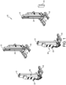
Figure 1 is a perspective view of an exemplary lift system including four mobile lift columns; -
Figure 2 is a front perspective view of an exemplary mobile lift columns of the lift system; -
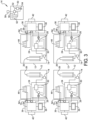
Figure 3 is a schematic block diagram of the lift system ofFigure 1 ; -
Figure 4 is an exemplary control unit display of a shimming procedure for leveling a mobile lift column determined to be un-level; -
Figure 5 is a block diagram of a prognostic sequence for determining a battery condition; -
Figure 6 is a graph of voltage verses time for analyzing a rate of change of voltage while under load for diagnosing a battery deterioration condition; -
Figure 7 is a graph of voltage verses time for analyzing a change in resting voltage between cycles for diagnosing a battery deterioration condition; -
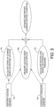
Figure 8 is a block diagram of a prognostic sequence for detecting an abnormal mobile lift column component condition; and -
Figure 9 is a block diagram of a prognostic sequence for monitoring message error rates between the remote control unit and the plurality of mobile lift columns. - Corresponding reference numerals indicate corresponding parts throughout the several views of the drawings.
- Example embodiments will now be described more fully with reference to the accompanying drawings.
- Example embodiments are provided so that this invention will be thorough, and will fully convey the scope to those who are skilled in the art. Numerous specific details are set forth such as examples of specific components, devices, and methods, to provide a thorough understanding of embodiments of the present invention. It will be apparent to those skilled in the art that specific details need not be employed, that example embodiments may be embodied in many different forms and that neither should be construed to limit the scope of the invention. In some example embodiments, well-known processes, well-known device structures, and well-known technologies are not described in detail.
- The terminology used herein is for the purpose of describing particular example embodiments only and is not intended to be limiting. As used herein, the singular forms "a," "an," and "the" may be intended to include the plural forms as well, unless the context clearly indicates otherwise. The terms "comprises," "comprising," "including," and "having," are inclusive and therefore specify the presence of stated features, integers, steps, operations, elements, and/or components, but do not preclude the presence or addition of one or more other features, integers, steps, operations, elements, components, and/or groups thereof. The method steps, processes, and operations described herein are not to be construed as necessarily requiring their performance in the particular order discussed or illustrated, unless specifically identified as an order of performance. It is also to be understood that additional or alternative steps may be employed.
- When an element or layer is referred to as being "on," "engaged to," "connected to," or "coupled to" another element or layer, it may be directly on, engaged, connected or coupled to the other element or layer, or intervening elements or layers may be present. In contrast, when an element is referred to as being "directly on," "directly engaged to," "directly connected to," or "directly coupled to" another element or layer, there may be no intervening elements or layers present. Other words used to describe the relationship between elements should be interpreted in a like fashion (e.g., "between" versus "directly between," "adjacent" versus "directly adjacent," etc.). As used herein, the term "and/or" includes any and all combinations of one or more of the associated listed items.
- Although the terms first, second, third, etc. may be used herein to describe various elements, components, regions, layers and/or sections, these elements, components, regions, layers and/or sections should not be limited by these terms. These terms may be only used to distinguish one element, component, region, layer, or section from another region, layer, or section. Terms such as "first," "second," and other numerical terms when used herein do not imply a sequence or order unless clearly indicated by the context. Thus, a first element, component, region, layer, or section discussed below could be termed a second element, component, region, layer, or section without departing from the teachings of the example embodiments.
-
Figure 1 illustrating anexemplary lift system 10 comprising a plurality ofmobile lift columns 12 and aremote control unit 14. Theremote control unit 14 is operable for controlling themobile lift columns 12 to selectively raise or lower a vehicle relative to the ground. While fourmobile lift columns 12 are shown, it should be understood that any other suitable number of columns 12 (e.g., six, eight, etc.) may be used to form thelift system 10. Eachmobile lift column 12 is shown to include a set oflegs 16 that support mobile lifting column12 in relation to the ground.Mobile lift column 12 is also shown to include a support fixture or acarrier 18 to provide support of the vehicle in relation tolifting column 12. - As further shown in
Figure 2 , themobile lift columns 12 also havewheels 20 and handles 22, permitting thecolumns 12 to be moved along the ground. Themobile lift columns 12 may thus be selectively positioned with relative ease, as may be desired to accommodate different vehicles having different wheel spacing or numbers of wheels (e.g., to move additionalmobile lift columns 12 into place or to move excessmobile lift columns 12 away, etc.), to replace a firstmobile lift column 12 with a secondmobile lift column 12 for maintenance of the firstmobile lift column 12, etc. - As shown in
Figure 2 , eachmobile lift column 12 further comprises a lift mechanism which is shown as ahydraulic system 24. Thehydraulic system 24 is operable to move acarrier 18 vertically relative to the ground. Thecarrier 18 is configured to engage a component of the vehicle (e.g., the wheel, etc.), to thereby enable themobile lift columns 12 to raise and lower the vehicle relative to the ground. The configuration of thecarrier 18 can vary to accommodate various vehicles as would be understood by one skilled in the art. - As shown in further detail in
Figure 3 , in the exemplary embodiment, eachhydraulic system 24 of the present example can include a hydraulic cylinder andpiston 26, apump 28, and a series ofvalves 30 controlling the flow of hydraulic fluid. In particular, thepump 28 andvalves 30 are in fluid communication with hydraulic cylinder andpiston 26, such that thepump 28 and thevalves 30 communicate fluid to or from the cylinder andpiston 26. Thecarrier 18 ascends and descends with the piston of hydraulic cylinder andpiston 26, such that thepump 28 and thevalves 30 may be controlled to control the vertical height at whichcarrier 18 is positioned. - A
processor 34 is in electrical communication with thepump 28 and thevalves 30 to control operation of thepump 28 and thevalves 30. Of course, any other suitable structures, components, or techniques may be used for ahydraulic system 24. For instance, any suitable systems, features, mechanisms, or components may be used in addition to or in lieu ofhydraulic system 24, including but not limited to a screw, belt, or gear mechanism, such as to raise orlower carrier 18. - Each
lift column 12 further includes acontrol unit 36, which may be used to control the operation, monitoring, and/or programming oflift system 10. For instance, any one of thecontrol units 36 may be used to define participation in ad hoc column control groups based on availablemobile lift columns 12, then control themobile lift columns 12 while in the ad hoc column control group.Control unit 36 can also have adisplay 38 that is configured to provide the operator with a visual indication ofmobile lift columns 12 have been assigned to the ad hoc column control group.Display 38 may include a graphical representation of a vehicle and graphical representations of the availablemobile lift columns 12 positioned in relation to the graphical representation of the vehicle.Control unit 36 may illuminate the graphical representations of the availablemobile lift columns 12 that have been selected for the ad hoc control group, providing the operator with immediate visual confirmation mobile of which liftcolumns 12 have been selected and where thosemobile lift columns 12 are in relation to the vehicle.Control unit 36 includes aprocessor 34, which is operable to process and relay information/commands to/from other components of thecontrol unit 36. - It should be understood that each
control unit 36 may be in communication with aremote control unit 14. For instance, when an operator uses acontrol unit 36 to create an ad hoc column control group, the identity of thecolumns 12 in that control group may be transmitted to theremote control unit 14. In addition, a lift command entered throughcontrol unit 36 may be sent to theremote control unit 14, andremote control unit 14 may then relay the lift command to themobile lift columns 12 that have been assigned to the ad hoc column control group. The remote control unit may function as the system controller. In alternate embodiments, the system controller may be a separate unit in wireless communication with both theremote control unit 14 and thecontrol unit 36, or the system controller may be one of thecontrol units 36 on one of thecolumns 12 existing in the system. - A
wireless transceiver 42 is also provided at eachcolumn 12 represented inFIG. 3 , and is operable to wirelessly relay information and commands between acolumn 12 and theremote control unit 14 as will be described in greater detail below. Thewireless transceiver 42 can be a radio frequency (RF) transceiver and/or may take other forms that will be apparent to those of ordinary skill in the art in view of the teachings herein. - As also shown in
FIG. 3 ,mobile lift column 12 includes arespective battery 44. Thebatteries 44 are rechargeable and are operable to power all aspects of operation of their respectivemobile lift columns 12. In particular, eachbattery 44 is operable to power thepump 28,control unit 36,transceiver 42, and/or any other electrically powered component in eachcolumn 12. - The
remote control unit 14 can include ahousing 50 having adisplay 52 and a series ofinput buttons 54. Input buttons may be designated for controlling lift motion or for navigating display menus on the remote control. Input buttons designated for controlling lift motion may only be enabled when the lift system is enabled for wireless remote lift operation. Theremote control unit 14 can further include aprocessor 56 in communication with thedisplay 52 and the series ofinput buttons 54 as well as a wireless transmitter/receiver 58. Theremote control unit 14 includes abattery 62. Thebattery 62 can be rechargeable and operable to power all aspects of operation of theremote control unit 14. In particular, thebattery 62 is operable to power thedisplay 52, theprocessor 56, the wireless transmitter/receiver 58, and/or any other electrically powered component in theremote control unit 14. Theinput buttons 54 can be incorporated into a touch screen of thedisplay 52 or can be separate input buttons. - As shown in
Figure 3 , each of themobile lift columns 12 further includes aninclinometer 64 for detecting an amount of tilt of themobile lift columns 12. Theinclinometer 64 can be calibrated to a zero position at which point the column is standing parallel to gravity. Theremote control unit 14 can poll eachmobile lift column 12 to determine if any column is too far out of level, or if two or more columns are tilted too far in opposite directions that could cause errors during lifting. Based upon the detected amount of tilt of themobile lift columns 12, theprocessor 56 of theremote control unit 14 can determine and display a correct shimming procedure for enabling level lifting, as shown inFigure 4 . For example, the shim height may be calculated by multiplying the distance between the shimmed load pads by the tangent of the floor slope angle between them. The remote may then round to the nearest shim height that will minimize the tilt of the column. In the particular, shimmingprocedure display illustration 66 shown inFigure 4 , the addition of a ½inch shim plate 68 is recommended to be added to a forward end of theleft leg 16 and a ¼inch shim plate 70 is recommended to be added to a rear end of theleft leg 16. It should be understood that other types of level compensation devices could be utilized including height adjustable feet supported by an adjustment screw, by a cam mechanism that can be adjusted to level themobile lifting columns 12 or an automated leveling system that can be controlled by theremote control unit 14 to compensate for leveling themobile lift columns 12. - With reference to
Figure 3 , themobile lift columns 12 include abattery voltage sensor 72 associated with thebatteries 44 and ahydraulic pressure sensor 74 associated with thehydraulic system 24. When a motor load is applied to thebattery 44, the voltage will drop and then continue to drift down until the load is removed, at which point the battery voltage will recover back to a new resting voltage. As shown inFigure 5 , the present example uses thebattery voltage sensor 72 to calculate the battery state-of-charge of thebattery 44 based on a resting voltage atstep 76. Atstep 78, the system calculates a motor load based on the hydraulic pressure from thehydraulic pressure sensor 74. The system further measures the voltage drop of thebattery 44 when a load is applied atstep 80. For example, based on characterizing a battery, the system may expect a voltage drop of one volt per 4000 pounds of applied load on thecarrier 16 for a battery in good condition. - As shown in
Figure 6 , the system can utilize the voltage rate of change of thebattery 44 while under load to estimate the battery condition. For example, the system may expect a rate of change of .0015 volt/second per 1000 pounds applied to the carrier for a battery in good condition. Further, as shown inFigure 7 , the system can utilize a change in the battery resting voltage between cycles to estimate the battery condition. For example, the system may expect a difference of 0.25V between resting cycles based on a measured load and cycle duration. The system then estimates and reports the current battery condition. If the battery condition does not represent a predetermined battery response condition, the user can be notified that the battery is deteriorating so that maintenance can be considered. - In a lift system, the system controller will monitor the position of separate lifting cylinders and equalize them. In the current state, lift equalization problems may only be found when the component deteriorates to the point of causing out-of-level error messages. The lift will engage a hydraulic correction valve to divert flow and equalize the lift cylinders in the system under normal conditions. In abnormal cases, the controller will have to engage a secondary valve to provide hard equalization in order to equalize the system. Particular factors contributing to hard equalization include an unequal battery state-of-charge amongst
mobile lift columns 12, an unequal amount of load amongst themobile lift columns 12, and the component issues such as a blocked hydraulic valve, a leaky pump and motor wear. Thebattery voltage sensors 72 and thehydraulic pressure sensors 74 can be utilized to monitor and understand the amount of equalization caused by abnormal causes and provide an indicator that an equalization component may be out-of-tolerance for troubleshooting and maintenance purposes. - As shown in
Figure 8 , the prognostic sequence can include calculating an amount of charge variation in the system based on each of thebattery voltage sensors 72 of themobile lift columns 12, atstep 82. In addition, the system can calculate an amount of load variation in the system based on each of thehydraulic pressure sensors 74 of themobile lift columns 12, atstep 84. The system can then determine if the variation is normal or can report an abnormal component message if the variation is abnormal atstep 86. For instance, if the system detects a variation in battery voltage of greater than five volts, the system would alert the user to check battery charge and status. Alternatively, if the difference in loads between columns is above 3:1, the system would alert the user to check and redistribute the weight. If battery and loading are within tolerance, the system would recommend a service call to inspect the hydraulic system. - The present invention can also monitor the message error rate between the individual
mobile lift columns 12 and the system controller of the mobile column lift system. The systems can give a user an indication of marginally performing radio links before communication errors start to occur frequently. As shown inFigure 9 , the processor can calculate the message air rate for eachmobile lift column 12 atstep 90. Atstep 92, the system can estimate the probability for communication errors based on message error rates and the total number ofmobile lift columns 12 in the system. The system can then display a message error rate for each column, if the probability for communication errors exceeds a desired threshold, the user can be alerted to the weak communication link resulting in a message error rate above the desired threshold atstep 94. For instance, the system may be comprised of four columns and the system controller may send twenty messages per second evenly amongst the columns. An error may be generated if a response is not heard from every column within a predetermined time, such as one second. The user may wish to be alerted if the message error rates results in a greater than 50% chance of error in ten minutes of operation. The probability of error can be calculated as 1-(1-(1-(error rate))^(messages sent by remote per second/total number of columns))^((desired minutes between error)*60). In this case, if the message error rate of any column goes above 25%, the system will alter the user to the weak radio link. The system may further indicate whether messages were missed when sent from the system controller or the column controller to isolate which radio may be faulty. - The foregoing description of the embodiments has been provided for purposes of illustration and description. It is not intended to be exhaustive or to limit the invention Individual elements or features of a particular embodiment are generally not limited to that particular embodiment, but, where applicable, are interchangeable and can be used in a selected embodiment, even if not specifically shown or described. The same may also be varied in many ways. Such variations are not to be regarded as a departure from the invention, and all such modifications are intended to be included within the scope of the invention.
Claims (4)
- A vehicle lift system, comprising:a plurality of mobile lift columns, each of the plurality of mobile lift columns further including an inclinometer for detecting an amount of tilt of the plurality of mobile lift columns;a control unit associated with the plurality of lift columns for controlling operation of the plurality of mobile lift columns, the control unit further receiving a signal indicative of the amount of tilt of each one of the plurality of mobile lift columns and providing a warning signal if any of the plurality of mobile lift column has an amount of tilt exceeding a predetermined amount.
- The vehicle lift system according to claim 1, wherein the control unit determines if two or more mobile lift columns are titled too far in opposite directions relative to one another that could cause errors during lifting.
- The vehicle lift system according to claim 1, wherein the control unit displays a tilt correction procedure for at least one of the plurality of mobile lift columns for enabling level lifting.
- The vehicle lift system according to claim 3, wherein the tilt correction procedure includes inserting shim plates under legs of at least one of the plurality of the mobile lift columns.
Priority Applications (1)
| Application Number | Priority Date | Filing Date | Title |
|---|---|---|---|
| EP24189949.1A EP4424632A3 (en) | 2019-05-28 | 2020-05-14 | System for vehicle lift monitoring and prognostics |
Applications Claiming Priority (2)
| Application Number | Priority Date | Filing Date | Title |
|---|---|---|---|
| US201962853248P | 2019-05-28 | 2019-05-28 | |
| PCT/US2020/032787 WO2020242771A1 (en) | 2019-05-28 | 2020-05-14 | System for vehicle lift monitoring and prognostics |
Related Child Applications (1)
| Application Number | Title | Priority Date | Filing Date |
|---|---|---|---|
| EP24189949.1A Division EP4424632A3 (en) | 2019-05-28 | 2020-05-14 | System for vehicle lift monitoring and prognostics |
Publications (3)
| Publication Number | Publication Date |
|---|---|
| EP3902765A1 EP3902765A1 (en) | 2021-11-03 |
| EP3902765A4 EP3902765A4 (en) | 2023-01-18 |
| EP3902765B1 true EP3902765B1 (en) | 2024-07-24 |
Family
ID=73551258
Family Applications (2)
| Application Number | Title | Priority Date | Filing Date |
|---|---|---|---|
| EP24189949.1A Pending EP4424632A3 (en) | 2019-05-28 | 2020-05-14 | System for vehicle lift monitoring and prognostics |
| EP20814414.7A Active EP3902765B1 (en) | 2019-05-28 | 2020-05-14 | System for vehicle lift monitoring and prognostics |
Family Applications Before (1)
| Application Number | Title | Priority Date | Filing Date |
|---|---|---|---|
| EP24189949.1A Pending EP4424632A3 (en) | 2019-05-28 | 2020-05-14 | System for vehicle lift monitoring and prognostics |
Country Status (4)
| Country | Link |
|---|---|
| US (3) | US11731867B2 (en) |
| EP (2) | EP4424632A3 (en) |
| CN (1) | CN113661141A (en) |
| WO (1) | WO2020242771A1 (en) |
Families Citing this family (7)
| Publication number | Priority date | Publication date | Assignee | Title |
|---|---|---|---|---|
| US11731867B2 (en) * | 2019-05-28 | 2023-08-22 | Vehicle Service Group, Llc | System for vehicle lift monitoring and prognostics |
| WO2020243252A2 (en) | 2019-05-28 | 2020-12-03 | Vehicle Service Group, Llc | Load-sensing vehicle lift |
| US20220348448A1 (en) * | 2021-04-30 | 2022-11-03 | Vehicle Service Group, Llc | Lift with halo light |
| US20230090066A1 (en) * | 2021-09-17 | 2023-03-23 | Fritel & Associates, LLC | Trailer stacking device |
| CN114408422A (en) * | 2021-12-24 | 2022-04-29 | 江苏智库智能科技有限公司 | Method for automatic leveling and change of hoisting platform, four-axis hoist and warehouse |
| DE102022100294B3 (en) * | 2022-01-07 | 2023-06-15 | Cory Drummond | Lifting device and lifting system |
| DE102022209269A1 (en) | 2022-09-06 | 2024-03-07 | Maha Maschinenbau Haldenwang Gmbh & Co. Kg | DATA TRANSMISSION DEVICE FOR A LIFT |
Family Cites Families (24)
| Publication number | Priority date | Publication date | Assignee | Title |
|---|---|---|---|---|
| GB2228919A (en) | 1989-02-03 | 1990-09-12 | Lloyd Edwin Clare | Lift for large vehicles. |
| KR100248569B1 (en) | 1993-12-22 | 2000-03-15 | 히가시 데쓰로 | Probe system |
| US6186280B1 (en) | 1999-09-14 | 2001-02-13 | Snap-On Technologies, Inc. | Lift safety system |
| WO2002034665A2 (en) | 2000-10-27 | 2002-05-02 | Delaware Capital Formation, Inc. | Electronically controlled vehicle lift and vehicle service system |
| US7191038B2 (en) | 2000-10-27 | 2007-03-13 | Rotary Lift, A Division Of Dover Industries | Electronically controlled vehicle lift and vehicle service system |
| JP5174421B2 (en) * | 2007-10-19 | 2013-04-03 | パナソニック株式会社 | Battery pack and battery system |
| US8025340B2 (en) | 2008-08-21 | 2011-09-27 | Foisie Michael R | Bed leveling system for dump truck |
| NL1035933C (en) * | 2008-09-15 | 2010-03-16 | Stertil Bv | System, lifting column and method for energy-efficient lifting and lowering a load. |
| US9352944B2 (en) | 2012-03-19 | 2016-05-31 | Gray Manufacturing Company, Inc. | Control and communication system for a wireless vehicle lift system |
| US20140324214A1 (en) * | 2013-04-30 | 2014-10-30 | Vehicle Service Group, Llc | Vehicle lift system with speed equalization and centralized control station |
| NL2011131C2 (en) * | 2013-07-10 | 2015-01-13 | Stertil Bv | Lifting system for lifting a vehicle comprising one or more lifting devices and a release system, and method there for. |
| NL2011132C2 (en) * | 2013-07-10 | 2015-01-13 | Stertil Bv | Lifting system for lifting a vehicle and method for operating the lifting system. |
| US9868621B2 (en) * | 2014-02-20 | 2018-01-16 | Gray Manufacturing Company, Inc. | Combustion-powered lift system |
| CA2882791C (en) * | 2014-02-28 | 2019-09-10 | Gray Manufacturing Company, Inc. | Vehicle lift system with advanced operating platform |
| NL2012679B1 (en) | 2014-04-24 | 2016-07-04 | Stertil Bv | Lifting system with central controller for lifting a vehicle with moveable lifting columns, and method there for. |
| CA2894807C (en) * | 2014-06-19 | 2020-03-31 | Stabilock, LLC | Trailer stabilizer and leveler |
| NL2013123B1 (en) * | 2014-07-04 | 2016-07-14 | Stertil Bv | Lifting device and system with integrated drive unit for lifting a vehicle, and method there for. |
| NL2015163B1 (en) * | 2015-07-14 | 2017-02-01 | Stertil Bv | Lifting system with PLC and method there for. |
| NL2015532B1 (en) * | 2015-09-30 | 2017-04-20 | Stertil Bv | Lifting system with indoor positioning system and method there for. |
| NL2018121B1 (en) * | 2017-01-04 | 2018-07-25 | Stertil Bv | Lifting device for lifting a vehicle with integrated motor control, and system and method therefor |
| NL2019831B1 (en) * | 2017-10-30 | 2019-05-08 | Anwb B V | Method and apparatus for indicating a state of health of a battery |
| NL2020438B3 (en) * | 2018-02-14 | 2026-02-26 | Stertil Bv | Lifting system with lock position sensor for load indication, and method therefor |
| CN110092009B (en) * | 2019-04-25 | 2024-05-14 | 沈阳飞研航空设备有限公司 | Intelligent electric bullet hanging vehicle for airplane |
| US11731867B2 (en) * | 2019-05-28 | 2023-08-22 | Vehicle Service Group, Llc | System for vehicle lift monitoring and prognostics |
-
2020
- 2020-04-29 US US16/862,527 patent/US11731867B2/en active Active
- 2020-05-14 EP EP24189949.1A patent/EP4424632A3/en active Pending
- 2020-05-14 WO PCT/US2020/032787 patent/WO2020242771A1/en not_active Ceased
- 2020-05-14 EP EP20814414.7A patent/EP3902765B1/en active Active
- 2020-05-14 CN CN202080025397.3A patent/CN113661141A/en active Pending
-
2023
- 2023-07-03 US US18/346,320 patent/US12280993B2/en active Active
-
2025
- 2025-03-20 US US19/085,396 patent/US20250214821A1/en active Pending
Also Published As
| Publication number | Publication date |
|---|---|
| EP3902765A1 (en) | 2021-11-03 |
| US20250214821A1 (en) | 2025-07-03 |
| EP4424632A2 (en) | 2024-09-04 |
| US20200377354A1 (en) | 2020-12-03 |
| US11731867B2 (en) | 2023-08-22 |
| US20230339736A1 (en) | 2023-10-26 |
| EP4424632A3 (en) | 2025-02-12 |
| US12280993B2 (en) | 2025-04-22 |
| WO2020242771A1 (en) | 2020-12-03 |
| EP3902765A4 (en) | 2023-01-18 |
| CN113661141A (en) | 2021-11-16 |
Similar Documents
| Publication | Publication Date | Title |
|---|---|---|
| US12280993B2 (en) | System for vehicle lift monitoring and prognostics | |
| US20240317107A1 (en) | Battery monitoring system for a lift device | |
| US20200248773A1 (en) | System to predict failures in shock absorbers | |
| CN113939471B (en) | Load-sensing type vehicle lifter | |
| JP2014091632A (en) | Outrigger pad monitoring device | |
| EP2927022A1 (en) | Caster wheel with constant force mechanism | |
| EP1889310B1 (en) | Battery electrolyte level control system | |
| CA2240397A1 (en) | Method of operating tyre pressure signalling devices on wheels fitted with pneumatic tyres | |
| JP2010510926A (en) | Vehicle load status display system | |
| JPH09267663A (en) | Vehicle operation control device | |
| US20180375371A1 (en) | Battery Monitoring and Control System | |
| US20210221650A1 (en) | Vacuum Adhesion System | |
| KR102394857B1 (en) | Alarm system and method for overweighed axle of suspension of vehicle, and system and method for expecting lifetime of spring of suspension of vehicle | |
| US20200247195A1 (en) | Method of determining the health of a tire on a vehicle | |
| EP3345859A1 (en) | Lifting device for lifting a vehicle with integrated motor control, and system and method therefor | |
| KR101997217B1 (en) | Device diagnostic system | |
| US20220050450A1 (en) | System and method for predicting shock absorber lifespan | |
| EP4381200A1 (en) | System to predict failures and duty life cycle in industrial shock absorbers based on pressure and temperature data | |
| KR20200122800A (en) | Track tension managing system for track and method for the same | |
| US12133102B2 (en) | Wireless communication system for monitoring conditions and position of slave apparatus | |
| US11761857B1 (en) | Device for rotating and inspecting tires | |
| KR102855582B1 (en) | Apparatus for displaying the remaining amount of gas with gas leak detection function | |
| US20250320098A1 (en) | Mast hydraulic sensing system and method | |
| EP2390528B1 (en) | Suspension system | |
| US20240210155A1 (en) | Determining idler wear based on position of idler assembly |
Legal Events
| Date | Code | Title | Description |
|---|---|---|---|
| STAA | Information on the status of an ep patent application or granted ep patent |
Free format text: STATUS: THE INTERNATIONAL PUBLICATION HAS BEEN MADE |
|
| PUAI | Public reference made under article 153(3) epc to a published international application that has entered the european phase |
Free format text: ORIGINAL CODE: 0009012 |
|
| STAA | Information on the status of an ep patent application or granted ep patent |
Free format text: STATUS: REQUEST FOR EXAMINATION WAS MADE |
|
| 17P | Request for examination filed |
Effective date: 20210730 |
|
| AK | Designated contracting states |
Kind code of ref document: A1 Designated state(s): AL AT BE BG CH CY CZ DE DK EE ES FI FR GB GR HR HU IE IS IT LI LT LU LV MC MK MT NL NO PL PT RO RS SE SI SK SM TR |
|
| DAV | Request for validation of the european patent (deleted) | ||
| DAX | Request for extension of the european patent (deleted) | ||
| RIC1 | Information provided on ipc code assigned before grant |
Ipc: B66F 17/00 20060101ALI20220913BHEP Ipc: B66F 3/46 20060101AFI20220913BHEP |
|
| REG | Reference to a national code |
Ref country code: DE Ref legal event code: R079 Free format text: PREVIOUS MAIN CLASS: B66F0007000000 Ipc: B66F0003460000 Ref document number: 602020034575 Country of ref document: DE |
|
| A4 | Supplementary search report drawn up and despatched |
Effective date: 20221220 |
|
| RIC1 | Information provided on ipc code assigned before grant |
Ipc: B66F 17/00 20060101ALI20221214BHEP Ipc: B66F 3/46 20060101AFI20221214BHEP |
|
| GRAP | Despatch of communication of intention to grant a patent |
Free format text: ORIGINAL CODE: EPIDOSNIGR1 |
|
| STAA | Information on the status of an ep patent application or granted ep patent |
Free format text: STATUS: GRANT OF PATENT IS INTENDED |
|
| INTG | Intention to grant announced |
Effective date: 20240314 |
|
| GRAS | Grant fee paid |
Free format text: ORIGINAL CODE: EPIDOSNIGR3 |
|
| GRAA | (expected) grant |
Free format text: ORIGINAL CODE: 0009210 |
|
| STAA | Information on the status of an ep patent application or granted ep patent |
Free format text: STATUS: THE PATENT HAS BEEN GRANTED |
|
| AK | Designated contracting states |
Kind code of ref document: B1 Designated state(s): AL AT BE BG CH CY CZ DE DK EE ES FI FR GB GR HR HU IE IS IT LI LT LU LV MC MK MT NL NO PL PT RO RS SE SI SK SM TR |
|
| REG | Reference to a national code |
Ref country code: GB Ref legal event code: FG4D |
|
| REG | Reference to a national code |
Ref country code: CH Ref legal event code: EP |
|
| REG | Reference to a national code |
Ref country code: DE Ref legal event code: R096 Ref document number: 602020034575 Country of ref document: DE |
|
| REG | Reference to a national code |
Ref country code: IE Ref legal event code: FG4D |
|
| REG | Reference to a national code |
Ref country code: NL Ref legal event code: FP |
|
| REG | Reference to a national code |
Ref country code: LT Ref legal event code: MG9D |
|
| PG25 | Lapsed in a contracting state [announced via postgrant information from national office to epo] |
Ref country code: PT Free format text: LAPSE BECAUSE OF FAILURE TO SUBMIT A TRANSLATION OF THE DESCRIPTION OR TO PAY THE FEE WITHIN THE PRESCRIBED TIME-LIMIT Effective date: 20241125 |
|
| REG | Reference to a national code |
Ref country code: AT Ref legal event code: MK05 Ref document number: 1706161 Country of ref document: AT Kind code of ref document: T Effective date: 20240724 |
|
| PG25 | Lapsed in a contracting state [announced via postgrant information from national office to epo] |
Ref country code: PT Free format text: LAPSE BECAUSE OF FAILURE TO SUBMIT A TRANSLATION OF THE DESCRIPTION OR TO PAY THE FEE WITHIN THE PRESCRIBED TIME-LIMIT Effective date: 20241125 |
|
| PG25 | Lapsed in a contracting state [announced via postgrant information from national office to epo] |
Ref country code: NO Free format text: LAPSE BECAUSE OF FAILURE TO SUBMIT A TRANSLATION OF THE DESCRIPTION OR TO PAY THE FEE WITHIN THE PRESCRIBED TIME-LIMIT Effective date: 20241024 |
|
| PG25 | Lapsed in a contracting state [announced via postgrant information from national office to epo] |
Ref country code: FI Free format text: LAPSE BECAUSE OF FAILURE TO SUBMIT A TRANSLATION OF THE DESCRIPTION OR TO PAY THE FEE WITHIN THE PRESCRIBED TIME-LIMIT Effective date: 20240724 Ref country code: PL Free format text: LAPSE BECAUSE OF FAILURE TO SUBMIT A TRANSLATION OF THE DESCRIPTION OR TO PAY THE FEE WITHIN THE PRESCRIBED TIME-LIMIT Effective date: 20240724 Ref country code: GR Free format text: LAPSE BECAUSE OF FAILURE TO SUBMIT A TRANSLATION OF THE DESCRIPTION OR TO PAY THE FEE WITHIN THE PRESCRIBED TIME-LIMIT Effective date: 20241025 |
|
| PG25 | Lapsed in a contracting state [announced via postgrant information from national office to epo] |
Ref country code: BG Free format text: LAPSE BECAUSE OF FAILURE TO SUBMIT A TRANSLATION OF THE DESCRIPTION OR TO PAY THE FEE WITHIN THE PRESCRIBED TIME-LIMIT Effective date: 20240724 |
|
| PG25 | Lapsed in a contracting state [announced via postgrant information from national office to epo] |
Ref country code: LV Free format text: LAPSE BECAUSE OF FAILURE TO SUBMIT A TRANSLATION OF THE DESCRIPTION OR TO PAY THE FEE WITHIN THE PRESCRIBED TIME-LIMIT Effective date: 20240724 |
|
| PG25 | Lapsed in a contracting state [announced via postgrant information from national office to epo] |
Ref country code: AT Free format text: LAPSE BECAUSE OF FAILURE TO SUBMIT A TRANSLATION OF THE DESCRIPTION OR TO PAY THE FEE WITHIN THE PRESCRIBED TIME-LIMIT Effective date: 20240724 Ref country code: IS Free format text: LAPSE BECAUSE OF FAILURE TO SUBMIT A TRANSLATION OF THE DESCRIPTION OR TO PAY THE FEE WITHIN THE PRESCRIBED TIME-LIMIT Effective date: 20241124 |
|
| PG25 | Lapsed in a contracting state [announced via postgrant information from national office to epo] |
Ref country code: HR Free format text: LAPSE BECAUSE OF FAILURE TO SUBMIT A TRANSLATION OF THE DESCRIPTION OR TO PAY THE FEE WITHIN THE PRESCRIBED TIME-LIMIT Effective date: 20240724 |
|
| PG25 | Lapsed in a contracting state [announced via postgrant information from national office to epo] |
Ref country code: ES Free format text: LAPSE BECAUSE OF FAILURE TO SUBMIT A TRANSLATION OF THE DESCRIPTION OR TO PAY THE FEE WITHIN THE PRESCRIBED TIME-LIMIT Effective date: 20240724 Ref country code: RS Free format text: LAPSE BECAUSE OF FAILURE TO SUBMIT A TRANSLATION OF THE DESCRIPTION OR TO PAY THE FEE WITHIN THE PRESCRIBED TIME-LIMIT Effective date: 20241024 |
|
| PG25 | Lapsed in a contracting state [announced via postgrant information from national office to epo] |
Ref country code: RS Free format text: LAPSE BECAUSE OF FAILURE TO SUBMIT A TRANSLATION OF THE DESCRIPTION OR TO PAY THE FEE WITHIN THE PRESCRIBED TIME-LIMIT Effective date: 20241024 Ref country code: PL Free format text: LAPSE BECAUSE OF FAILURE TO SUBMIT A TRANSLATION OF THE DESCRIPTION OR TO PAY THE FEE WITHIN THE PRESCRIBED TIME-LIMIT Effective date: 20240724 Ref country code: NO Free format text: LAPSE BECAUSE OF FAILURE TO SUBMIT A TRANSLATION OF THE DESCRIPTION OR TO PAY THE FEE WITHIN THE PRESCRIBED TIME-LIMIT Effective date: 20241024 Ref country code: LV Free format text: LAPSE BECAUSE OF FAILURE TO SUBMIT A TRANSLATION OF THE DESCRIPTION OR TO PAY THE FEE WITHIN THE PRESCRIBED TIME-LIMIT Effective date: 20240724 Ref country code: IS Free format text: LAPSE BECAUSE OF FAILURE TO SUBMIT A TRANSLATION OF THE DESCRIPTION OR TO PAY THE FEE WITHIN THE PRESCRIBED TIME-LIMIT Effective date: 20241124 Ref country code: HR Free format text: LAPSE BECAUSE OF FAILURE TO SUBMIT A TRANSLATION OF THE DESCRIPTION OR TO PAY THE FEE WITHIN THE PRESCRIBED TIME-LIMIT Effective date: 20240724 Ref country code: GR Free format text: LAPSE BECAUSE OF FAILURE TO SUBMIT A TRANSLATION OF THE DESCRIPTION OR TO PAY THE FEE WITHIN THE PRESCRIBED TIME-LIMIT Effective date: 20241025 Ref country code: FI Free format text: LAPSE BECAUSE OF FAILURE TO SUBMIT A TRANSLATION OF THE DESCRIPTION OR TO PAY THE FEE WITHIN THE PRESCRIBED TIME-LIMIT Effective date: 20240724 Ref country code: ES Free format text: LAPSE BECAUSE OF FAILURE TO SUBMIT A TRANSLATION OF THE DESCRIPTION OR TO PAY THE FEE WITHIN THE PRESCRIBED TIME-LIMIT Effective date: 20240724 Ref country code: BG Free format text: LAPSE BECAUSE OF FAILURE TO SUBMIT A TRANSLATION OF THE DESCRIPTION OR TO PAY THE FEE WITHIN THE PRESCRIBED TIME-LIMIT Effective date: 20240724 Ref country code: AT Free format text: LAPSE BECAUSE OF FAILURE TO SUBMIT A TRANSLATION OF THE DESCRIPTION OR TO PAY THE FEE WITHIN THE PRESCRIBED TIME-LIMIT Effective date: 20240724 |
|
| PG25 | Lapsed in a contracting state [announced via postgrant information from national office to epo] |
Ref country code: RO Free format text: LAPSE BECAUSE OF FAILURE TO SUBMIT A TRANSLATION OF THE DESCRIPTION OR TO PAY THE FEE WITHIN THE PRESCRIBED TIME-LIMIT Effective date: 20240724 Ref country code: SM Free format text: LAPSE BECAUSE OF FAILURE TO SUBMIT A TRANSLATION OF THE DESCRIPTION OR TO PAY THE FEE WITHIN THE PRESCRIBED TIME-LIMIT Effective date: 20240724 Ref country code: DK Free format text: LAPSE BECAUSE OF FAILURE TO SUBMIT A TRANSLATION OF THE DESCRIPTION OR TO PAY THE FEE WITHIN THE PRESCRIBED TIME-LIMIT Effective date: 20240724 |
|
| PG25 | Lapsed in a contracting state [announced via postgrant information from national office to epo] |
Ref country code: EE Free format text: LAPSE BECAUSE OF FAILURE TO SUBMIT A TRANSLATION OF THE DESCRIPTION OR TO PAY THE FEE WITHIN THE PRESCRIBED TIME-LIMIT Effective date: 20240724 |
|
| PG25 | Lapsed in a contracting state [announced via postgrant information from national office to epo] |
Ref country code: CZ Free format text: LAPSE BECAUSE OF FAILURE TO SUBMIT A TRANSLATION OF THE DESCRIPTION OR TO PAY THE FEE WITHIN THE PRESCRIBED TIME-LIMIT Effective date: 20240724 |
|
| REG | Reference to a national code |
Ref country code: DE Ref legal event code: R097 Ref document number: 602020034575 Country of ref document: DE |
|
| PG25 | Lapsed in a contracting state [announced via postgrant information from national office to epo] |
Ref country code: SK Free format text: LAPSE BECAUSE OF FAILURE TO SUBMIT A TRANSLATION OF THE DESCRIPTION OR TO PAY THE FEE WITHIN THE PRESCRIBED TIME-LIMIT Effective date: 20240724 |
|
| PLBE | No opposition filed within time limit |
Free format text: ORIGINAL CODE: 0009261 |
|
| STAA | Information on the status of an ep patent application or granted ep patent |
Free format text: STATUS: NO OPPOSITION FILED WITHIN TIME LIMIT |
|
| PGFP | Annual fee paid to national office [announced via postgrant information from national office to epo] |
Ref country code: NL Payment date: 20250530 Year of fee payment: 6 |
|
| 26N | No opposition filed |
Effective date: 20250425 |
|
| PGFP | Annual fee paid to national office [announced via postgrant information from national office to epo] |
Ref country code: DE Payment date: 20250528 Year of fee payment: 6 |
|
| PGFP | Annual fee paid to national office [announced via postgrant information from national office to epo] |
Ref country code: GB Payment date: 20250520 Year of fee payment: 6 |
|
| PGFP | Annual fee paid to national office [announced via postgrant information from national office to epo] |
Ref country code: IT Payment date: 20250522 Year of fee payment: 6 |
|
| PGFP | Annual fee paid to national office [announced via postgrant information from national office to epo] |
Ref country code: FR Payment date: 20250526 Year of fee payment: 6 |
|
| PG25 | Lapsed in a contracting state [announced via postgrant information from national office to epo] |
Ref country code: SE Free format text: LAPSE BECAUSE OF FAILURE TO SUBMIT A TRANSLATION OF THE DESCRIPTION OR TO PAY THE FEE WITHIN THE PRESCRIBED TIME-LIMIT Effective date: 20240724 |
|
| REG | Reference to a national code |
Ref country code: CH Ref legal event code: H13 Free format text: ST27 STATUS EVENT CODE: U-0-0-H10-H13 (AS PROVIDED BY THE NATIONAL OFFICE) Effective date: 20251223 |
|
| PG25 | Lapsed in a contracting state [announced via postgrant information from national office to epo] |
Ref country code: LU Free format text: LAPSE BECAUSE OF NON-PAYMENT OF DUE FEES Effective date: 20250514 |
|
| PG25 | Lapsed in a contracting state [announced via postgrant information from national office to epo] |
Ref country code: CH Free format text: LAPSE BECAUSE OF NON-PAYMENT OF DUE FEES Effective date: 20250531 |
|
| REG | Reference to a national code |
Ref country code: BE Ref legal event code: MM Effective date: 20250531 |
|
| PG25 | Lapsed in a contracting state [announced via postgrant information from national office to epo] |
Ref country code: MC Free format text: LAPSE BECAUSE OF FAILURE TO SUBMIT A TRANSLATION OF THE DESCRIPTION OR TO PAY THE FEE WITHIN THE PRESCRIBED TIME-LIMIT Effective date: 20240724 |
|
| PG25 | Lapsed in a contracting state [announced via postgrant information from national office to epo] |
Ref country code: IE Free format text: LAPSE BECAUSE OF NON-PAYMENT OF DUE FEES Effective date: 20250514 |
|
| PG25 | Lapsed in a contracting state [announced via postgrant information from national office to epo] |
Ref country code: BE Free format text: LAPSE BECAUSE OF NON-PAYMENT OF DUE FEES Effective date: 20250531 |