EP3902717B1 - Wischblatt - Google Patents
Wischblatt Download PDFInfo
- Publication number
- EP3902717B1 EP3902717B1 EP19832370.1A EP19832370A EP3902717B1 EP 3902717 B1 EP3902717 B1 EP 3902717B1 EP 19832370 A EP19832370 A EP 19832370A EP 3902717 B1 EP3902717 B1 EP 3902717B1
- Authority
- EP
- European Patent Office
- Prior art keywords
- wiper
- connection adapter
- wiper blade
- supporting element
- blade according
- Prior art date
- Legal status (The legal status is an assumption and is not a legal conclusion. Google has not performed a legal analysis and makes no representation as to the accuracy of the status listed.)
- Active
Links
Images


Classifications
-
- B—PERFORMING OPERATIONS; TRANSPORTING
- B60—VEHICLES IN GENERAL
- B60S—SERVICING, CLEANING, REPAIRING, SUPPORTING, LIFTING, OR MANOEUVRING OF VEHICLES, NOT OTHERWISE PROVIDED FOR
- B60S1/00—Cleaning of vehicles
- B60S1/02—Cleaning windscreens, windows or optical devices
- B60S1/04—Wipers or the like, e.g. scrapers
- B60S1/32—Wipers or the like, e.g. scrapers characterised by constructional features of wiper blade arms or blades
- B60S1/38—Wiper blades
- B60S1/3848—Flat-type wiper blade, i.e. without harness
- B60S1/3849—Connectors therefor; Connection to wiper arm; Attached to blade
- B60S1/3851—Mounting of connector to blade assembly
- B60S1/3853—Snap-fit, e.g. elastic connection
-
- B—PERFORMING OPERATIONS; TRANSPORTING
- B60—VEHICLES IN GENERAL
- B60S—SERVICING, CLEANING, REPAIRING, SUPPORTING, LIFTING, OR MANOEUVRING OF VEHICLES, NOT OTHERWISE PROVIDED FOR
- B60S1/00—Cleaning of vehicles
- B60S1/02—Cleaning windscreens, windows or optical devices
- B60S1/04—Wipers or the like, e.g. scrapers
- B60S1/32—Wipers or the like, e.g. scrapers characterised by constructional features of wiper blade arms or blades
- B60S1/38—Wiper blades
- B60S1/3848—Flat-type wiper blade, i.e. without harness
- B60S1/3874—Flat-type wiper blade, i.e. without harness with a reinforcing vertebra
- B60S1/3875—Flat-type wiper blade, i.e. without harness with a reinforcing vertebra rectangular section
- B60S1/3881—Flat-type wiper blade, i.e. without harness with a reinforcing vertebra rectangular section in additional element, e.g. spoiler
Definitions
- the invention relates to a wiper blade according to the generic type of the independent claim.
- Wiper blades which have an elastically flexible wiper strip carrier made of a plastic, in which a carrier element, in particular a strip-like spring steel, is inserted in a hollow channel.
- a connecting element for connecting the wiper blade to a wiper arm is also connected to the support element via recesses in the wiper strip element and corresponding profiles.
- a wiper blade adapter device in particular for a motor vehicle windshield wiper device, with a wiper blade adapter which has at least one spring-elastic latching means for coupling to a wiper strip unit, with at least one securing means being provided to secure the at least one latching means in a mounted state. If the latching means and the securing means are in the locking position, the latching means secures a carrier element of the wiper strip against displacement relative to the wiper blade in the longitudinal direction.
- a wiper blade with a support structure in which a flexible support element is inserted in the longitudinal direction and on the sides of which openings are formed for the lateral edges of the support element and a connector which is attached to the openings substantially transversely to the support structure and which in its Insertion direction is held by side edge portions of the support member protruding from the openings.
- the connector has at least one deformation extending within a notch formed on the support member at a side edge portion accessible through an opening and by which displacement of the support member is prevented.
- the wiper blade with the features of main claim 1 has the advantage that the support element is secured against displacement in the longitudinal direction. It cannot happen that the support element, for example a flat spring steel strip, shifts to a significant extent. This is particularly important because such a spring steel strip is pre-stressed and pre-bent in a way that is tailored to the use of the wiper blade, and this is the only way to distribute the contact pressure forces on the windshield over the entire length of the wiper blade. In the event of a shift, the wiper blade can no longer work as intended.
- the support element for example a flat spring steel strip
- the support element is advantageously a flat spring steel strip.
- the contact surfaces of the support element are formed by a cutout.
- a cutout In the simplest form and, for example, in the case of a spring steel strip, a small section can be cut out of this at the side, through which the blocking pin passes. If the support element or spring steel strip then wants to move in the longitudinal direction, it hits the blocking pin with the edges of the cutout in both directions.
- the blocking pin is a round pin with a bevel and locking edge, the bevel being able to slide over a locking edge when inserted into a bore and after the locking edge of the round pin can be held on the locking edge by the locking edge.
- a locking pin has a bevel that cooperates with a locking edge and it will lock when fully depressed, a will result simple and easy assembly option.
- An embodiment as a rotationally symmetrical round pin with a chamfer in the form of a cone results in an embodiment that can be produced inexpensively and is easy to assemble, since no orientation has to be observed.
- the round pin can also slide past, for example, a spring steel strip as a support element when it is inserted into a laterally arranged bore of the connection adapter.
- the round pin has a stop edge for the support element.
- connection adapter The contact surfaces in the connection adapter are advantageously formed by a partially open cylindrical surface. In its position, the round pin is then supported over a considerable part of its circumference and protrudes, for example, with its remaining circumference, which interacts with a recess in the support element.
- the bore can be arranged perpendicularly to the support element, which is designed as flat spring steel. This enables, for example, assembly by pushing it into the connection adapter from below in an area in which the wiper strip support is correspondingly open.
- the hole is advantageously arranged laterally at the edge of the spring steel strip.
- the wiper strip carrier is made of plastic and a wiper lip is co-extruded.
- the wiper strip support can be made of plastic and a spoiler can be co-extruded.
- plastics with different properties, in particular elastic polymers, a combination of different functions can be achieved cost-effectively in one component, such as wiper lip and spoiler in the example.
- a wiper blade can be produced cost-effectively with just a few components.
- the 1 shows a wiper blade 1 with a wiper strip carrier 2 on which a wiper lip 3 and a spoiler 4 are co-extruded.
- a connection adapter 5 is provided, which consists of a connection adapter upper part 6 and a connection adapter lower part 7, which is connected to the wiper strip carrier 2 and which are rotatably connected to one another by a joint 8.
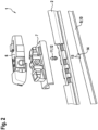
- the 2 shows the wiper blade 1 as an exploded view, with the connection adapter upper part 6, the connection adapter lower part 7, the wiper strip carrier 2 and a support element 9 in the form of a spring steel strip 10.
- a blocking pin 11 in the form of a round pin 12 is also shown, which has stop surfaces 13 in a recess 14 of the support element 8 interacts.
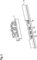
- the 3 shows the wiper strip support 2 with a connection adapter lower part 7.
- the wiper strip support 2 is shown in this illustration without the support element 9.
- Recesses 15 of the wiper strip carrier are present in such a way that when a support element 9 is located in a channel opened by the recesses 15, the support element 9 can be surrounded by holding elements of the connection adapter lower part 7 and thus the connection adapter lower part 7 and the wiper strip carrier 2 are connected to one another.
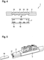
- the 4 shows the wiper strip carrier 2 and the connection adapter lower part 7 from the underside.
- the recesses 15 in the wiper strip carrier 3 expose a channel for the support element 9 or the spring steel strip 10 .
- Corresponding retaining elements 16 are located in the positions of the recesses 15 when the connection adapter lower part 7 is in place.
- the figure 5 shows the wiper blade 1 in an assembly position.
- the spring steel strip 10 is pushed into a channel 17 in the wiper strip support 2 from the front end.
- the 6 shows the wiper strip carrier 2 with the inserted support element 9 in the form of the spring steel strip 10 and the lower part of the connection adapter 7 in a sectioned representation arranged above it.
- the retaining elements 16 can engage around the spring steel strip 10 with a groove 18 .
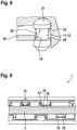
- the 7 shows a detailed view of the lower part of the connection adapter 7 in cross section.
- the recess 14 of the spring steel strip 10 comes to rest aligned with the bore 20 .
- the 8 shows a detailed view in cross section with a blocking pin 11 or round pin 12 inserted.
- the round pin 12 When the round pin 12 is pushed in, it is guided past the spring steel strip 10 with the beveled cone 21 .
- the round pin 12 reaches its end position via a locking edge 23, in which it is held by the locking edge 22 on the locking edge 23, as shown. In this position, the middle section of the round pin 12 is in the recess 14 of the spring steel strip 10.
- a stop edge 24 rests against the spring steel strip 10.
- the 9 shows a view of the wiper blade 1 from below in the area of the connection adapter 5 with its connection adapter lower part 7.
- the spring steel strip 10 is visible in the recesses 15 of the wiper strip carrier 2 and is surrounded by holding elements 16 here.
- the round pin 12 secures the spring steel strip 10 against displacement in the longitudinal direction.
Landscapes
- Engineering & Computer Science (AREA)
- Mechanical Engineering (AREA)
- Connection Of Plates (AREA)
- Pivots And Pivotal Connections (AREA)
- Snaps, Bayonet Connections, Set Pins, And Snap Rings (AREA)
Description
- Die Erfindung betrifft ein Wischblatt nach der Gattung des unabhängigen Anspruchs.
- Es sind Wischblätter bekannt, die einen elastisch nachgiebigen Wischleistenträger aus einem Kunststoff aufweisen, in dem in einen Hohlkanal ein Tragelement, insbesondere ein bandartiger Federstahl, eingesetzt ist. Ein Anschlusselement zur Verbindung des Wischblatt mit einem Wischarm ist dabei über Aussparungen des Wischleistenelements und entsprechende Profile ebenfalls mit dem Tragelement verbunden.
- Aus der
DE 10 2011 005 171 A1 ist eine Wischblattadaptervorrichtung, insbesondere für eine Kraftfahrzeugscheibenwischvorrichtung, mit einem Wischblattadapter bekannt, der zumindest ein federelastisches Rastmittel zum Koppeln an eine Wischleisteneinheit aufweist, wobei zumindest ein Sicherungsmittel dazu vorgesehen ist, das zumindest eine Rastmittel in einem montierten Zustand zu sichern. Wenn sich das Rastmittel und das Sicherungsmittel in der Verriegelungsposition befinden, sichert das Rastmittel ein Trägerelement der Wischleiste vor einem Verschieben relativ zum Wischblatt in Längsrichtung. - Aus der
FR 2925001 B1 FR-A-2871127 - Das Wischblatt mit den Merkmalen des Hauptanspruchs 1 hat den Vorteil, dass das Tragelement in Längsrichtung gegen Verschiebungen gesichert wird. Es kann nicht vorkommen, dass sich das Tragelement, beispielsweise ein flaches Federstahlband in erheblichem Maße verschiebt. Dies ist insbesondere wichtig, da eine Vorspannung und Vorbiegung eines solchen Federstahlbandes abgestimmt auf den Einsatz des Wischblatt erfolgt und nur durch dieses die Anpresskräfte auf die Windschutzscheibe über die gesamte Länge des Wischblatt verteilt werden. Bei einer Verschiebung kann das Wischblatt nicht mehr bestimmungsgemäß arbeiten. Ein Gesamtaufbau mit einem Wischleistenträger, in den das Trägerelement eingeschoben wird und als weiteres Bauteil nur ein Anschluss Adapter erforderlich ist, da beispielsweise die Wischlippe oder ein Spoiler co-extrudiert bzw. im Spritzgussverfahren angespritzt werden, ist jedoch eine vorteilhafte Ausführungsform mit nur wenigen Bauteilen. Durch die Merkmale des unabhängigen Anspruchs kann diese kostengünstige und leicht zu montierende Bauform eingesetzt werden, ohne dass es zu Verschiebungen des Federstahlbandes kommt. Wenn das Tragelement, insbesondere ein einzelnes Federstahlband abwechselnd durch den Kanal des Wischleistenträgers und im Bereich von Ausnehmungen des Wischleistenträgers durch beispielsweise Nuten von Halteelementen des Anschlussadapters geführt wird, so wird der Anschlussadapter nicht demontierbar fest mit dem Wischblatt verbunden.
- Durch die in den Unteransprüchen aufgeführten Maßnahmen ergeben sich weiterhin vorteilhafte Weiterbildungen und Verbesserungen der in dem Hauptanspruch angegebenen Merkmale.
- Vorteilhaft ist das das Tragelement ein flaches Federstahlband.
- In einer günstigen Ausgestaltung werden die Anlageflächen des Tragelements durch einen Ausschnitt gebildet. In der einfachsten Form und beispielsweise bei einem Federstahlband kann seitlich ein kleiner Ausschnitt aus diesem herausgeschnitten sein, durch den der Blockierstift hindurchführt. Wenn sich das Tragelement bzw. Federstahlband dann in Längsrichtung bewegen will, schlägt es mit den Kanten des Ausschnitts jeweils in beiden Richtungen auf den Blockierstift auf.
- Nach der Erfindung ist der Blockierstift ein Rundstift mit Kegelabschrägung und Arretierungskante, wobei die Kegelabschrägung beim Einsetzen in eine Bohrung über eine Rastkante gleiten kann und nach dem Einrasten der Rundstift an der Arretierungskante durch die Rastkante gehalten werden kann. Wenn ein Blockierstift eine Abschrägung aufweist, die mit einer Rastkante zusammenwirkt, und er bei vollständigem Eindrücken einrastet, ergibt sich eine einfache und leichte Montagemöglichkeit. Eine Ausführung als rotationsymmetrischer Rundstift mit einer Abschrägung in Kegelform ergibt eine kostengünstig herzustellende Ausführung, die leicht zu montieren ist, da keine Orientierung eingehalten werden muss. Zugleich kann durch eine solche Abschrägung der Rundstift auch an beispielsweise einem Federstahlband als Tragelement vorbeigleiten, wenn er in eine seitlich angeordnete Bohrung des Anschluss Adapter eingeführt wird.
- In günstiger Ausgestaltung weist der Rundstift eine Anschlagkante für das Tragelement auf.
- Vorteilhaft werden die Anlageflächen im Anschlussadapter durch eine teilweise offenen Zylinderfläche gebildet. In seiner Position ist der Rundstift dann über einen erheblichen Teil seines Umfangs abgestützt und steht beispielsweise mit seinem restlichen Umfang vor, der mit einer Ausnehmung des Tragelements zusammen wirkt.
- Die Bohrung kann senkrecht zu dem als flachen Federstahl ausgebildeten Tragelement angeordnet sein. Dies ermöglicht beispielsweise eine Montage durch Einschieben von unten in den Anschlussadapter in einem Bereich, in dem der Wischleistenträger entsprechend offen ist.
- Vorteilhaft ist die Bohrung seitlich am Rand des Federstahlbands angeordnet.
- In einer vorteilhaften Weiterbildung besteht der Wischleistenträger aus Kunststoff und ist eine Wischlippe co-extrudiert angeformt.
- Der Wischleistenträger kann aus Kunststoff bestehen und ein Spoiler co-extrudiert angeformt sein. Durch die Kombination von Kunststoffen mit unterschiedlichen Eigenschaften, insbesondere elastischen Polymeren, kann kostengünstig in einem Bauteil eine Kombination verschiedener Funktionen erreicht werden, wie im Beispielsfall Wischlippe und Spoiler. Durch die bisher schon beschriebenen Merkmale lässt sich insgesamt ein Wischblatt mit wenigen Bauteilen kostengünstig Herstellen.
- Ausführungsbeispiele sind in den Zeichnungen dargestellt und in der nachfolgenden Beschreibung näher erläutert. Es zeigen:
- Fig. 1
- ein Wischblatt,
- Fig. 2
- das Wischblatt als Sprengbild,
- Fig. 3
- einen Wischleistenträger mit einem Anschlussadapterunterteil,
- Fig. 4
- den Wischleistenträger und das Anschlussadapterunterteil,
- Fig. 5
- das Wischblatt in einer Montageposition,
- Fig. 6
- den Wischleistenträger mit Tragelement und Anschlussadapterunterteil,
- Fig. 7
- im Querschnitt eine Detailansicht,
- Fig. 8
- im Querschnitt eine Detailansicht mit einem eingesetzten Blockierstift und
- Fig. 9
- eine Ansicht auf das Wischblatt von unten im Bereich des Anschlussadapters.
- Die
Fig. 1 zeigt ein Wischblatt 1, mit einem Wischleistenträger 2, an dem co-extrudiert eine Wischlippe 3 sowie ein Spoiler 4 angeformt sind. Zur Verbindung des Wischblatts 1 mit einem Wischarm ist ein Anschlussadapter 5 vorgesehen, der aus einem Anschlussadapteroberteil 6 und einem Anschlussadapterunterteil 7, das mit dem Wischleistenträger 2 verbunden ist, besteht und die durch ein Gelenk 8 drehbar miteinander verbunden sind. - Die
Fig. 2 zeigt das Wischblatt 1 als Sprengbild, mit dem Anschlussadapteroberteil 6, dem Anschlussadapterunterteil 7, dem Wischleistenträger 2 und einem Tragelement 9 in Form eines Federstahlbandes 10. Zusätzlich ist noch ein Blockierstift 11 in Form eines Rundstifts 12 dargestellt, der mit Anschlagflächen 13 in einer Ausnehmung 14 des Tragelements 8 zusammenwirkt. - Die
Fig. 3 zeigt den Wischleistenträger 2 mit einem Anschlussadapterunterteil 7. Der Wischleistenträger 2 ist in dieser Darstellung ohne Tragelement 9 abgebildet. Es sind Ausnehmungen 15 des Wischleistenträger so vorhanden, dass wenn ein Tragelement 9 in einem durch die Ausnehmungen 15 geöffneten Kanal sich befindet, das Tragelement 9 von Halteelementen des Anschlussadapterunterteil 7 umfasst werden kann und somit das Anschlussadapterunterteil 7 und der Wischleistenträger 2 miteinander verbunden werden. - Die
Fig. 4 zeigt den Wischleistenträger 2 und von der Unterseite das Anschlussadapterunterteil 7. Die Ausnehmungen 15 in dem Wischleistenträger 3 legen einen Kanal für das Tragelement 9 bzw. das Federstahlband 10 frei. In den Positionen der Ausnehmungen 15 befinden sich bei aufgesetztem Anschlussadapterunterteil 7 entsprechende Halteelemente 16. - Die
Fig. 5 zeigt das Wischblatt 1 in einer Montageposition. Um den Wischleistenträger 2 und das Anschlussadapterunterteil 7 miteinander zu verbinden, wird das Federstahlband 10 vom Stirnende her in einen Kanal 17 in dem Wischleistenträger 2 eingeschoben. - Die
Fig. 6 zeigt den Wischleistenträger 2 mit eingesetztem Tragelement 9 in Form des Federstahlbandes 10 und Anschlussadapterunterteil 7 in angeschnittener Darstellung darüber angeordnet. Die Halteelemente 16 können mit einer Nut 18 das Federstahlband 10 umgreifen. - Die
Fig. 7 zeigt im Querschnitt eine Detailansicht des Anschlussadapterunterteils 7. Das Federstahlband 10 ist durch das Anschlussadapterunterteil 7 hindurchgeführt und wird von den Halteelementen 16 und deren Nuten 18 umgriffen. Seitlich zu dem Federstahlband 10 befindet sich eine Bohrung 20, in die der Blockierstift 11 in Form des Rundstifts 12 eingesetzt werden kann, die durch ihre Zylinderfläche 25 als Anlageflächen 26 in dem Anschlussadapter 5 den Rundstift 12 abstützt. An seiner Oberseite besitzt der Rundstift 12 eine Kegelabschrägung 21 und darunter eine Arretierungskante 22. Mit der Bohrung 20 ausgerichtet kommt die Ausnehmung 14 des Federstahlbands 10 zu liegen. - Die
Fig. 8 zeigt im Querschnitt eine Detailansicht mit einem eingesetzten Blockierstift 11 bzw. Rundstift 12. Beim Hineindrücken des Rundstifts 12 geleitet dieser mit der Kegelabschrägung 21 an dem Federstahlband 10 vorbei. Ebenso kommt durch die Kegelabschrägung 21 der Rundstift 12 über eine Rastkante 23 bis in seine Endposition, in der er durch die Arretierungskante 22 an der Rastkante 23 gehalten wird, wie dargestellt. In dieser Position befindet sich der mittlere Abschnitt des Rundstifts 12 in der Ausnehmung 14 des Federstahlbands 10. Eine Anschlagkante 24 liegt an dem Federstahlband 10 an. - Die
Fig. 9 zeigt eine Ansicht auf das Wischblatt 1 von unten im Bereich des Anschlussadapters 5 mit seinem Anschlussadapterunterteil 7. Das Federstahlband 10 ist in den Ausnehmungen 15 des Wischleistenträgers 2 sichtbar und wird hier von Halteelemente 16 umgriffen. Der Rundstift 12 sichert das Federstahlband 10 gegen eine Verschiebung in der Längsrichtung.
Claims (9)
- Wischblatt mit einem Anschlussadapter (5) und mindestens einer Wischleiste (1) und einem elastisch nachgiebigen Wischleistenträger (2), insbesondere aus Kunststoff, der im Querschnitt in einem oder mehreren Kanälen (17) ein Tragelement (9) aufnimmt, wobei das Tragelement (9) im Bereich des Anschlussadapters (5) in Ausnehmungen (15) des Wischleistenträgers (2) zumindest teilweise von Halteelementen (16) des Anschlussadapters (5) umgriffen wird, sodass durch das Tragelement (9) der Anschlussadapter (5) mit dem Wischleistenträger (2) verbunden wird, wobei ein in den Anschlussadapter (5) eingeschobener Blockierstift (11) durch Anlageflächen (26) im Anschlussadapter (5) wie auch Anlageflächen des Tragelements (9) das Tragelement (9) in seiner Position in Längsrichtung des Wischleistenträgers (2) in Bezug auf den Anschlussadapter (5) festlegt, dadurch gekennzeichnet, dass der Blockierstift (11) ein Rundstift (12) mit Kegelabschrägung (21) und Arretierungskante (22) ist, wobei die Kegelabschrägung (21) beim Einsetzen in eine Bohrung (20) über eine Rastkante (23) gleiten kann und nach dem Einrasten der Rundstift (12) an der Arretierungskante (22) durch die Rastkante (23) gehalten werden kann.
- Wischblatt nach Anspruch 1,
dadurch gekennzeichnet,
dass das Tragelement (9) ein flaches Federstahlband (10) ist. - Wischblatt nach Anspruch 1 oder 2,
dadurch gekennzeichnet,
dass die Anlageflächen des Tragelements (9) durch einen Ausschnitt (14) gebildet werden. - Wischblatt nach einem der vorhergehenden Ansprüche,
dadurch gekennzeichnet,
dass der Rundstift (12) eine Anschlagkante (24) für das Tragelement (9) aufweist. - Wischblatt nach einem der vorhergehenden Ansprüche,
dadurch gekennzeichnet,
dass die Anlageflächen (26) im Anschlussadapter (5) durch eine teilweise offenen Zylinderfläche (25) gebildet werden. - Wischblatt nach einem der vorhergehenden Ansprüche,
dadurch gekennzeichnet,
dass die Bohrung (20) senkrecht zu dem als flachen Federstahl (10) ausgebildeten Tragelement (9) angeordnet ist. - Wischblatt nach Anspruch 6,
dadurch gekennzeichnet,
dass die Bohrung (20) seitlich am Rand des Federstahlbands (10) angeordnet ist - Wischblatt nach einem der vorhergehenden Ansprüche,
dadurch gekennzeichnet,
dass der Wischleistenträger (2) aus Kunststoff besteht und eine Wischlippe (3) co-extrudiert angeformt ist. - Wischblatt nach einem der vorhergehenden Ansprüche,
dadurch gekennzeichnet,
dass der Wischleistenträger (2) aus Kunststoff besteht und ein Spoiler (4) co-extrudiert angeformt ist.
Applications Claiming Priority (2)
| Application Number | Priority Date | Filing Date | Title |
|---|---|---|---|
| DE102018251733.9A DE102018251733A1 (de) | 2018-12-27 | 2018-12-27 | Wischblatt |
| PCT/EP2019/086401 WO2020136089A1 (de) | 2018-12-27 | 2019-12-19 | Wischblatt |
Publications (2)
| Publication Number | Publication Date |
|---|---|
| EP3902717A1 EP3902717A1 (de) | 2021-11-03 |
| EP3902717B1 true EP3902717B1 (de) | 2023-08-16 |
Family
ID=69137879
Family Applications (1)
| Application Number | Title | Priority Date | Filing Date |
|---|---|---|---|
| EP19832370.1A Active EP3902717B1 (de) | 2018-12-27 | 2019-12-19 | Wischblatt |
Country Status (4)
| Country | Link |
|---|---|
| EP (1) | EP3902717B1 (de) |
| CN (1) | CN113226869B (de) |
| DE (1) | DE102018251733A1 (de) |
| WO (1) | WO2020136089A1 (de) |
Family Cites Families (9)
| Publication number | Priority date | Publication date | Assignee | Title |
|---|---|---|---|---|
| FR2871127B1 (fr) * | 2004-06-03 | 2007-09-07 | Valeo Systemes Dessuyage | Balai d'essuie-glace plat notamment pour vehicule automobile |
| FR2884204B1 (fr) * | 2005-04-07 | 2007-07-13 | Renault Sas | Axe d'articulation a geometrie variable |
| FR2925001B1 (fr) | 2007-12-18 | 2010-02-12 | Valeo Systemes Dessuyage | Balai d'essuie-glace dote d'un connecteur et procede de fabrication d'un tel balai |
| US20090223010A1 (en) * | 2008-03-10 | 2009-09-10 | Richey Sean Z | Windshield wiper system |
| KR100918979B1 (ko) * | 2009-01-21 | 2009-09-25 | 정현찬 | 변전 멀티 블레이드를 갖는 와이퍼 |
| DE102011005171A1 (de) | 2011-03-07 | 2012-09-13 | Robert Bosch Gmbh | Wischblattadaptervorrichtung, insbesondere für eine Kraftfahrzeugscheibenwischvorrichtung |
| JP6031509B2 (ja) * | 2011-04-13 | 2016-11-24 | フェデラル−モグル エス.エー.Federal−Mogul.S.A. | フロントガラス用ワイパー装置 |
| KR101933747B1 (ko) * | 2011-08-31 | 2018-12-28 | 페더랄-모굴 에스.아. | 윈드스크린 와이퍼 장치 |
| JP6740099B2 (ja) * | 2016-11-21 | 2020-08-12 | 株式会社ミツバ | ワイパブレードの製造方法 |
-
2018
- 2018-12-27 DE DE102018251733.9A patent/DE102018251733A1/de not_active Withdrawn
-
2019
- 2019-12-19 CN CN201980086732.8A patent/CN113226869B/zh active Active
- 2019-12-19 EP EP19832370.1A patent/EP3902717B1/de active Active
- 2019-12-19 WO PCT/EP2019/086401 patent/WO2020136089A1/de not_active Ceased
Also Published As
| Publication number | Publication date |
|---|---|
| WO2020136089A1 (de) | 2020-07-02 |
| DE102018251733A1 (de) | 2020-07-02 |
| EP3902717A1 (de) | 2021-11-03 |
| CN113226869A (zh) | 2021-08-06 |
| CN113226869B (zh) | 2024-08-16 |
Similar Documents
| Publication | Publication Date | Title |
|---|---|---|
| EP2229301B1 (de) | Wischblatt | |
| EP2259954B1 (de) | Wischblatt | |
| EP2190703B1 (de) | Wischblatt | |
| EP0624133B1 (de) | Wischblatt zum überstreichen von scheiben an kraftfahrzeugen | |
| EP1347896B1 (de) | Wischvorrichtung, insbesondere für scheiben von kraftfahrzeugen | |
| EP0749378B1 (de) | Wischblatt | |
| DE10043427B4 (de) | Wischvorrichtung | |
| DE2735627A1 (de) | Wischvorrichtung fuer scheiben von kraftfahrzeugen | |
| EP2177407A1 (de) | Wischblatt | |
| EP3902717B1 (de) | Wischblatt | |
| DE102006061703A1 (de) | Verbindungsanordnung | |
| WO2012079854A1 (de) | Wischblattvorrichtung | |
| DE102016215033A1 (de) | Bewegungstolerante Befestigungseinrichtung | |
| DE102015204945A1 (de) | Clipelement | |
| DE2856111A1 (de) | Wischvorrichtung fuer scheiben von kraftfahrzeugen | |
| EP2734421B1 (de) | Wischblatt mit einer adaptereinheit zur anlenkung an einem wischerarm | |
| DE202007009721U1 (de) | An einem Bauteil formschlüssig festgelegte Halteeinrichtung | |
| WO2020212327A1 (de) | Windabweiser für eine scheibenwischanlage eines kraftwagens | |
| DE102023213068A1 (de) | Wischerarm, insbesondere für ein Kraftfahrzeug | |
| DE102022124493A1 (de) | Endstück für eine Zier- oder Schachtleiste, Zier- oder Schachtleiste und Anordnung einer Zier- oder Schachtleiste an einem Fahrzeug | |
| EP2055966B1 (de) | Profilsprosse | |
| DE102022132437A1 (de) | Befestigungsclip mit Montageindikator | |
| DE102013212781A1 (de) | Wischblattvorrichtung | |
| DE102011077519A1 (de) | Wischblatt zum Reinigen von Scheiben insbesondere von Kraftfahrzeugen | |
| DE102013112712A1 (de) | Wischblatt zum Reinigen einer Fahrzeugscheibe, Verfahren zur Montage eines Wischblatts, Wischvorrichtung und Versorgungselement für eine Waschflüssigkeit |
Legal Events
| Date | Code | Title | Description |
|---|---|---|---|
| STAA | Information on the status of an ep patent application or granted ep patent |
Free format text: STATUS: UNKNOWN |
|
| STAA | Information on the status of an ep patent application or granted ep patent |
Free format text: STATUS: THE INTERNATIONAL PUBLICATION HAS BEEN MADE |
|
| PUAI | Public reference made under article 153(3) epc to a published international application that has entered the european phase |
Free format text: ORIGINAL CODE: 0009012 |
|
| STAA | Information on the status of an ep patent application or granted ep patent |
Free format text: STATUS: REQUEST FOR EXAMINATION WAS MADE |
|
| 17P | Request for examination filed |
Effective date: 20210727 |
|
| AK | Designated contracting states |
Kind code of ref document: A1 Designated state(s): AL AT BE BG CH CY CZ DE DK EE ES FI FR GB GR HR HU IE IS IT LI LT LU LV MC MK MT NL NO PL PT RO RS SE SI SK SM TR |
|
| DAV | Request for validation of the european patent (deleted) | ||
| DAX | Request for extension of the european patent (deleted) | ||
| GRAP | Despatch of communication of intention to grant a patent |
Free format text: ORIGINAL CODE: EPIDOSNIGR1 |
|
| STAA | Information on the status of an ep patent application or granted ep patent |
Free format text: STATUS: GRANT OF PATENT IS INTENDED |
|
| INTG | Intention to grant announced |
Effective date: 20230510 |
|
| GRAS | Grant fee paid |
Free format text: ORIGINAL CODE: EPIDOSNIGR3 |
|
| GRAA | (expected) grant |
Free format text: ORIGINAL CODE: 0009210 |
|
| STAA | Information on the status of an ep patent application or granted ep patent |
Free format text: STATUS: THE PATENT HAS BEEN GRANTED |
|
| AK | Designated contracting states |
Kind code of ref document: B1 Designated state(s): AL AT BE BG CH CY CZ DE DK EE ES FI FR GB GR HR HU IE IS IT LI LT LU LV MC MK MT NL NO PL PT RO RS SE SI SK SM TR |
|
| REG | Reference to a national code |
Ref country code: CH Ref legal event code: EP |
|
| REG | Reference to a national code |
Ref country code: DE Ref legal event code: R096 Ref document number: 502019008996 Country of ref document: DE |
|
| REG | Reference to a national code |
Ref country code: IE Ref legal event code: FG4D Free format text: LANGUAGE OF EP DOCUMENT: GERMAN |
|
| REG | Reference to a national code |
Ref country code: LT Ref legal event code: MG9D |
|
| REG | Reference to a national code |
Ref country code: NL Ref legal event code: MP Effective date: 20230816 |
|
| PG25 | Lapsed in a contracting state [announced via postgrant information from national office to epo] |
Ref country code: GR Free format text: LAPSE BECAUSE OF FAILURE TO SUBMIT A TRANSLATION OF THE DESCRIPTION OR TO PAY THE FEE WITHIN THE PRESCRIBED TIME-LIMIT Effective date: 20231117 |
|
| PG25 | Lapsed in a contracting state [announced via postgrant information from national office to epo] |
Ref country code: IS Free format text: LAPSE BECAUSE OF FAILURE TO SUBMIT A TRANSLATION OF THE DESCRIPTION OR TO PAY THE FEE WITHIN THE PRESCRIBED TIME-LIMIT Effective date: 20231216 |
|
| PG25 | Lapsed in a contracting state [announced via postgrant information from national office to epo] |
Ref country code: SE Free format text: LAPSE BECAUSE OF FAILURE TO SUBMIT A TRANSLATION OF THE DESCRIPTION OR TO PAY THE FEE WITHIN THE PRESCRIBED TIME-LIMIT Effective date: 20230816 Ref country code: RS Free format text: LAPSE BECAUSE OF FAILURE TO SUBMIT A TRANSLATION OF THE DESCRIPTION OR TO PAY THE FEE WITHIN THE PRESCRIBED TIME-LIMIT Effective date: 20230816 Ref country code: PT Free format text: LAPSE BECAUSE OF FAILURE TO SUBMIT A TRANSLATION OF THE DESCRIPTION OR TO PAY THE FEE WITHIN THE PRESCRIBED TIME-LIMIT Effective date: 20231218 Ref country code: NO Free format text: LAPSE BECAUSE OF FAILURE TO SUBMIT A TRANSLATION OF THE DESCRIPTION OR TO PAY THE FEE WITHIN THE PRESCRIBED TIME-LIMIT Effective date: 20231116 Ref country code: NL Free format text: LAPSE BECAUSE OF FAILURE TO SUBMIT A TRANSLATION OF THE DESCRIPTION OR TO PAY THE FEE WITHIN THE PRESCRIBED TIME-LIMIT Effective date: 20230816 Ref country code: LV Free format text: LAPSE BECAUSE OF FAILURE TO SUBMIT A TRANSLATION OF THE DESCRIPTION OR TO PAY THE FEE WITHIN THE PRESCRIBED TIME-LIMIT Effective date: 20230816 Ref country code: LT Free format text: LAPSE BECAUSE OF FAILURE TO SUBMIT A TRANSLATION OF THE DESCRIPTION OR TO PAY THE FEE WITHIN THE PRESCRIBED TIME-LIMIT Effective date: 20230816 Ref country code: IS Free format text: LAPSE BECAUSE OF FAILURE TO SUBMIT A TRANSLATION OF THE DESCRIPTION OR TO PAY THE FEE WITHIN THE PRESCRIBED TIME-LIMIT Effective date: 20231216 Ref country code: HR Free format text: LAPSE BECAUSE OF FAILURE TO SUBMIT A TRANSLATION OF THE DESCRIPTION OR TO PAY THE FEE WITHIN THE PRESCRIBED TIME-LIMIT Effective date: 20230816 Ref country code: GR Free format text: LAPSE BECAUSE OF FAILURE TO SUBMIT A TRANSLATION OF THE DESCRIPTION OR TO PAY THE FEE WITHIN THE PRESCRIBED TIME-LIMIT Effective date: 20231117 Ref country code: FI Free format text: LAPSE BECAUSE OF FAILURE TO SUBMIT A TRANSLATION OF THE DESCRIPTION OR TO PAY THE FEE WITHIN THE PRESCRIBED TIME-LIMIT Effective date: 20230816 |
|
| PG25 | Lapsed in a contracting state [announced via postgrant information from national office to epo] |
Ref country code: PL Free format text: LAPSE BECAUSE OF FAILURE TO SUBMIT A TRANSLATION OF THE DESCRIPTION OR TO PAY THE FEE WITHIN THE PRESCRIBED TIME-LIMIT Effective date: 20230816 |
|
| PG25 | Lapsed in a contracting state [announced via postgrant information from national office to epo] |
Ref country code: ES Free format text: LAPSE BECAUSE OF FAILURE TO SUBMIT A TRANSLATION OF THE DESCRIPTION OR TO PAY THE FEE WITHIN THE PRESCRIBED TIME-LIMIT Effective date: 20230816 |
|
| PG25 | Lapsed in a contracting state [announced via postgrant information from national office to epo] |
Ref country code: SM Free format text: LAPSE BECAUSE OF FAILURE TO SUBMIT A TRANSLATION OF THE DESCRIPTION OR TO PAY THE FEE WITHIN THE PRESCRIBED TIME-LIMIT Effective date: 20230816 Ref country code: RO Free format text: LAPSE BECAUSE OF FAILURE TO SUBMIT A TRANSLATION OF THE DESCRIPTION OR TO PAY THE FEE WITHIN THE PRESCRIBED TIME-LIMIT Effective date: 20230816 Ref country code: ES Free format text: LAPSE BECAUSE OF FAILURE TO SUBMIT A TRANSLATION OF THE DESCRIPTION OR TO PAY THE FEE WITHIN THE PRESCRIBED TIME-LIMIT Effective date: 20230816 Ref country code: EE Free format text: LAPSE BECAUSE OF FAILURE TO SUBMIT A TRANSLATION OF THE DESCRIPTION OR TO PAY THE FEE WITHIN THE PRESCRIBED TIME-LIMIT Effective date: 20230816 Ref country code: DK Free format text: LAPSE BECAUSE OF FAILURE TO SUBMIT A TRANSLATION OF THE DESCRIPTION OR TO PAY THE FEE WITHIN THE PRESCRIBED TIME-LIMIT Effective date: 20230816 Ref country code: CZ Free format text: LAPSE BECAUSE OF FAILURE TO SUBMIT A TRANSLATION OF THE DESCRIPTION OR TO PAY THE FEE WITHIN THE PRESCRIBED TIME-LIMIT Effective date: 20230816 Ref country code: SK Free format text: LAPSE BECAUSE OF FAILURE TO SUBMIT A TRANSLATION OF THE DESCRIPTION OR TO PAY THE FEE WITHIN THE PRESCRIBED TIME-LIMIT Effective date: 20230816 |
|
| REG | Reference to a national code |
Ref country code: DE Ref legal event code: R097 Ref document number: 502019008996 Country of ref document: DE |
|
| PLBE | No opposition filed within time limit |
Free format text: ORIGINAL CODE: 0009261 |
|
| STAA | Information on the status of an ep patent application or granted ep patent |
Free format text: STATUS: NO OPPOSITION FILED WITHIN TIME LIMIT |
|
| 26N | No opposition filed |
Effective date: 20240517 |
|
| PG25 | Lapsed in a contracting state [announced via postgrant information from national office to epo] |
Ref country code: IT Free format text: LAPSE BECAUSE OF FAILURE TO SUBMIT A TRANSLATION OF THE DESCRIPTION OR TO PAY THE FEE WITHIN THE PRESCRIBED TIME-LIMIT Effective date: 20230816 Ref country code: SI Free format text: LAPSE BECAUSE OF FAILURE TO SUBMIT A TRANSLATION OF THE DESCRIPTION OR TO PAY THE FEE WITHIN THE PRESCRIBED TIME-LIMIT Effective date: 20230816 |
|
| REG | Reference to a national code |
Ref country code: CH Ref legal event code: PL |
|
| PG25 | Lapsed in a contracting state [announced via postgrant information from national office to epo] |
Ref country code: LU Free format text: LAPSE BECAUSE OF NON-PAYMENT OF DUE FEES Effective date: 20231219 |
|
| PG25 | Lapsed in a contracting state [announced via postgrant information from national office to epo] |
Ref country code: MC Free format text: LAPSE BECAUSE OF FAILURE TO SUBMIT A TRANSLATION OF THE DESCRIPTION OR TO PAY THE FEE WITHIN THE PRESCRIBED TIME-LIMIT Effective date: 20230816 |
|
| GBPC | Gb: european patent ceased through non-payment of renewal fee |
Effective date: 20231219 |
|
| REG | Reference to a national code |
Ref country code: BE Ref legal event code: MM Effective date: 20231231 |
|
| PG25 | Lapsed in a contracting state [announced via postgrant information from national office to epo] |
Ref country code: MC Free format text: LAPSE BECAUSE OF FAILURE TO SUBMIT A TRANSLATION OF THE DESCRIPTION OR TO PAY THE FEE WITHIN THE PRESCRIBED TIME-LIMIT Effective date: 20230816 Ref country code: LU Free format text: LAPSE BECAUSE OF NON-PAYMENT OF DUE FEES Effective date: 20231219 |
|
| REG | Reference to a national code |
Ref country code: IE Ref legal event code: MM4A |
|
| PG25 | Lapsed in a contracting state [announced via postgrant information from national office to epo] |
Ref country code: IE Free format text: LAPSE BECAUSE OF NON-PAYMENT OF DUE FEES Effective date: 20231219 |
|
| PG25 | Lapsed in a contracting state [announced via postgrant information from national office to epo] |
Ref country code: GB Free format text: LAPSE BECAUSE OF NON-PAYMENT OF DUE FEES Effective date: 20231219 |
|
| PG25 | Lapsed in a contracting state [announced via postgrant information from national office to epo] |
Ref country code: BE Free format text: LAPSE BECAUSE OF NON-PAYMENT OF DUE FEES Effective date: 20231231 |
|
| PG25 | Lapsed in a contracting state [announced via postgrant information from national office to epo] |
Ref country code: CH Free format text: LAPSE BECAUSE OF NON-PAYMENT OF DUE FEES Effective date: 20231231 |
|
| PG25 | Lapsed in a contracting state [announced via postgrant information from national office to epo] |
Ref country code: IE Free format text: LAPSE BECAUSE OF NON-PAYMENT OF DUE FEES Effective date: 20231219 Ref country code: GB Free format text: LAPSE BECAUSE OF NON-PAYMENT OF DUE FEES Effective date: 20231219 Ref country code: CH Free format text: LAPSE BECAUSE OF NON-PAYMENT OF DUE FEES Effective date: 20231231 Ref country code: BE Free format text: LAPSE BECAUSE OF NON-PAYMENT OF DUE FEES Effective date: 20231231 |
|
| PG25 | Lapsed in a contracting state [announced via postgrant information from national office to epo] |
Ref country code: BG Free format text: LAPSE BECAUSE OF FAILURE TO SUBMIT A TRANSLATION OF THE DESCRIPTION OR TO PAY THE FEE WITHIN THE PRESCRIBED TIME-LIMIT Effective date: 20230816 |
|
| PG25 | Lapsed in a contracting state [announced via postgrant information from national office to epo] |
Ref country code: BG Free format text: LAPSE BECAUSE OF FAILURE TO SUBMIT A TRANSLATION OF THE DESCRIPTION OR TO PAY THE FEE WITHIN THE PRESCRIBED TIME-LIMIT Effective date: 20230816 |
|
| PG25 | Lapsed in a contracting state [announced via postgrant information from national office to epo] |
Ref country code: CY Free format text: LAPSE BECAUSE OF FAILURE TO SUBMIT A TRANSLATION OF THE DESCRIPTION OR TO PAY THE FEE WITHIN THE PRESCRIBED TIME-LIMIT; INVALID AB INITIO Effective date: 20191219 |
|
| PG25 | Lapsed in a contracting state [announced via postgrant information from national office to epo] |
Ref country code: HU Free format text: LAPSE BECAUSE OF FAILURE TO SUBMIT A TRANSLATION OF THE DESCRIPTION OR TO PAY THE FEE WITHIN THE PRESCRIBED TIME-LIMIT; INVALID AB INITIO Effective date: 20191219 |
|
| PG25 | Lapsed in a contracting state [announced via postgrant information from national office to epo] |
Ref country code: TR Free format text: LAPSE BECAUSE OF FAILURE TO SUBMIT A TRANSLATION OF THE DESCRIPTION OR TO PAY THE FEE WITHIN THE PRESCRIBED TIME-LIMIT Effective date: 20230816 |
|
| PGFP | Annual fee paid to national office [announced via postgrant information from national office to epo] |
Ref country code: FR Payment date: 20251218 Year of fee payment: 7 |
|
| REG | Reference to a national code |
Ref country code: AT Ref legal event code: MM01 Ref document number: 1599757 Country of ref document: AT Kind code of ref document: T Effective date: 20241219 |
|
| PGFP | Annual fee paid to national office [announced via postgrant information from national office to epo] |
Ref country code: DE Payment date: 20260223 Year of fee payment: 7 |
|
| PG25 | Lapsed in a contracting state [announced via postgrant information from national office to epo] |
Ref country code: AT Free format text: LAPSE BECAUSE OF NON-PAYMENT OF DUE FEES Effective date: 20241219 |
|
| PGFP | Annual fee paid to national office [announced via postgrant information from national office to epo] |
Ref country code: AT Payment date: 20260410 Year of fee payment: 5 |