EP3902691B1 - Non-pneumatic tire having reinforced outer ring - Google Patents
Non-pneumatic tire having reinforced outer ring Download PDFInfo
- Publication number
- EP3902691B1 EP3902691B1 EP19906197.9A EP19906197A EP3902691B1 EP 3902691 B1 EP3902691 B1 EP 3902691B1 EP 19906197 A EP19906197 A EP 19906197A EP 3902691 B1 EP3902691 B1 EP 3902691B1
- Authority
- EP
- European Patent Office
- Prior art keywords
- outer ring
- tread
- tire
- pneumatic tire
- layer
- Prior art date
- Legal status (The legal status is an assumption and is not a legal conclusion. Google has not performed a legal analysis and makes no representation as to the accuracy of the status listed.)
- Active
Links
Images




Classifications
-
- B—PERFORMING OPERATIONS; TRANSPORTING
- B60—VEHICLES IN GENERAL
- B60C—VEHICLE TYRES; TYRE INFLATION; TYRE CHANGING; CONNECTING VALVES TO INFLATABLE ELASTIC BODIES IN GENERAL; DEVICES OR ARRANGEMENTS RELATED TO TYRES
- B60C7/00—Non-inflatable or solid tyres
- B60C7/10—Non-inflatable or solid tyres characterised by means for increasing resiliency
- B60C7/14—Non-inflatable or solid tyres characterised by means for increasing resiliency using springs
-
- B—PERFORMING OPERATIONS; TRANSPORTING
- B29—WORKING OF PLASTICS; WORKING OF SUBSTANCES IN A PLASTIC STATE IN GENERAL
- B29D—PRODUCING PARTICULAR ARTICLES FROM PLASTICS OR FROM SUBSTANCES IN A PLASTIC STATE
- B29D30/00—Producing pneumatic or solid tyres or parts thereof
- B29D30/02—Solid tyres ; Moulds therefor
-
- B—PERFORMING OPERATIONS; TRANSPORTING
- B60—VEHICLES IN GENERAL
- B60C—VEHICLE TYRES; TYRE INFLATION; TYRE CHANGING; CONNECTING VALVES TO INFLATABLE ELASTIC BODIES IN GENERAL; DEVICES OR ARRANGEMENTS RELATED TO TYRES
- B60C7/00—Non-inflatable or solid tyres
- B60C7/10—Non-inflatable or solid tyres characterised by means for increasing resiliency
- B60C7/102—Tyres built-up with separate rubber parts
-
- B—PERFORMING OPERATIONS; TRANSPORTING
- B60—VEHICLES IN GENERAL
- B60C—VEHICLE TYRES; TYRE INFLATION; TYRE CHANGING; CONNECTING VALVES TO INFLATABLE ELASTIC BODIES IN GENERAL; DEVICES OR ARRANGEMENTS RELATED TO TYRES
- B60C7/00—Non-inflatable or solid tyres
- B60C7/10—Non-inflatable or solid tyres characterised by means for increasing resiliency
- B60C7/14—Non-inflatable or solid tyres characterised by means for increasing resiliency using springs
- B60C7/143—Non-inflatable or solid tyres characterised by means for increasing resiliency using springs having a lateral extension disposed in a plane parallel to the wheel axis
-
- B—PERFORMING OPERATIONS; TRANSPORTING
- B60—VEHICLES IN GENERAL
- B60C—VEHICLE TYRES; TYRE INFLATION; TYRE CHANGING; CONNECTING VALVES TO INFLATABLE ELASTIC BODIES IN GENERAL; DEVICES OR ARRANGEMENTS RELATED TO TYRES
- B60C7/00—Non-inflatable or solid tyres
- B60C7/10—Non-inflatable or solid tyres characterised by means for increasing resiliency
- B60C7/14—Non-inflatable or solid tyres characterised by means for increasing resiliency using springs
- B60C7/146—Non-inflatable or solid tyres characterised by means for increasing resiliency using springs extending substantially radially, e.g. like spokes
-
- B—PERFORMING OPERATIONS; TRANSPORTING
- B60—VEHICLES IN GENERAL
- B60C—VEHICLE TYRES; TYRE INFLATION; TYRE CHANGING; CONNECTING VALVES TO INFLATABLE ELASTIC BODIES IN GENERAL; DEVICES OR ARRANGEMENTS RELATED TO TYRES
- B60C7/00—Non-inflatable or solid tyres
- B60C7/10—Non-inflatable or solid tyres characterised by means for increasing resiliency
- B60C7/14—Non-inflatable or solid tyres characterised by means for increasing resiliency using springs
- B60C7/16—Non-inflatable or solid tyres characterised by means for increasing resiliency using springs of helical or flat coil form
- B60C7/18—Non-inflatable or solid tyres characterised by means for increasing resiliency using springs of helical or flat coil form disposed radially relative to wheel axis
-
- B—PERFORMING OPERATIONS; TRANSPORTING
- B60—VEHICLES IN GENERAL
- B60C—VEHICLE TYRES; TYRE INFLATION; TYRE CHANGING; CONNECTING VALVES TO INFLATABLE ELASTIC BODIES IN GENERAL; DEVICES OR ARRANGEMENTS RELATED TO TYRES
- B60C7/00—Non-inflatable or solid tyres
- B60C7/22—Non-inflatable or solid tyres having inlays other than for increasing resiliency, e.g. for armouring
-
- B—PERFORMING OPERATIONS; TRANSPORTING
- B60—VEHICLES IN GENERAL
- B60C—VEHICLE TYRES; TYRE INFLATION; TYRE CHANGING; CONNECTING VALVES TO INFLATABLE ELASTIC BODIES IN GENERAL; DEVICES OR ARRANGEMENTS RELATED TO TYRES
- B60C9/00—Reinforcements or ply arrangement of pneumatic tyres
- B60C9/18—Structure or arrangement of belts or breakers, crown-reinforcing or cushioning layers
- B60C9/20—Structure or arrangement of belts or breakers, crown-reinforcing or cushioning layers built-up from rubberised plies each having all cords arranged substantially parallel
- B60C9/2003—Structure or arrangement of belts or breakers, crown-reinforcing or cushioning layers built-up from rubberised plies each having all cords arranged substantially parallel characterised by the materials of the belt cords
- B60C9/2006—Structure or arrangement of belts or breakers, crown-reinforcing or cushioning layers built-up from rubberised plies each having all cords arranged substantially parallel characterised by the materials of the belt cords consisting of steel cord plies only
Definitions
- the present invention relates to a non-pneumatic tire, and a method of making the same.
- Non-pneumatic tires do not require inflation, while "run flat tires” may continue to operate after receiving a puncture and a complete or partial loss of pressurized air, for extended periods of time and at relatively high speeds.
- Non-pneumatic tires may include a plurality of spokes, a webbing, or other support structure that connects an inner ring to an outer ring.
- a circumferential tread may be wrapped about the outer ring of the tire. The circumferential tread may contain a shear element having an elastic region disposed between upper and lower inelastic regions.
- US 4 235 270 A describes a tire having an annular body of resilient elastomeric material with an outer member at the outer periphery which may carry a tread and an inner member at the inner periphery for mounting on a wheel rim.
- the inner member is supported and cushioned by a plurality of circumferentially spaced-apart wall members extending from the inner member to the outer member.
- the annular body may have one or more supporting rings and the wall members of adjacent rings as well as the wall members of the same ring may be offset circumferentially of the tire.
- the wall members provide a lateral spring rate and a variable radial spring rate across the tread of the tire.
- the wall members, tread, inner member and outer member may be reinforced by cords extending at bias angles or generally circumferentially of the tire. Sidewalls between the inner and outer members may also be provided for low pressure inflation and exclusion of foreign matter from the spaces between the wall members.
- JP 2009 286208 A describes a non-pneumatic tire that comprises a spoke structure in which an outer circumferential wheel and an inner circumferential wheel coaxially arranged are connected via a plurality of fins arranged in the circumferential direction with a space therebetween, and a tread ring attached to the outer circumferential side of the spoke structure.
- a wire is embedded in the outer circumferential wheel of the spoke structure so as to be across at least between a pair of adjacent fins.
- JP 2013 032072 A describes a non-pneumatic tire that includes the support structure for supporting the load from the vehicle, and the tread layer adjacently arranged on the outer peripheral side of the support structure.
- the support structure has an inside annular part, an outside annular part arranged in a concentric circular shape outside the inside annular part, and a plurality of connecting parts joined to the inside annular part and the outside annular part and connecting both.
- the outside annular part is constituted of a first annular layer, and a second annular layer laminated on the outer peripheral side of the first annular layer and lower in a modulus than the first annular layer.
- the tread layer is constituted of a first tread layer, and a second tread layer laminated on the inner peripheral side of the first tread layer and higher in the modulus than the first tread layer.
- JP 2011 178308 A describes a non-pneumatic tire that includes: a support structure having an inside annular part, an outside annular part arranged in a concentrically circular shape outside the inside annular part and a plurality of connecting parts and for connecting the inside annular part and the outside annular part and respectively independent in the peripheral direction, and supporting a load from a vehicle; and an air sac arranged outside the support structure, and having a skin part forming a flat doughnut shape in the tire axial direction and a hollow part formed so that air can be filled inside the skin part.
- JP 2008 044445 A describes a plurality of through holes that are formed in a tire circumferential direction of an annular tread buried with belt layers comprising a steel cord, the belt layers are arranged so as to be left from the through holes in a tire width direction, and a reinforcement layer comprising a resin cord extending in the tire width direction is arranged separately from the belt layers.
- non-pneumatic tire that includes an inner ring having an axis of rotation and an outer ring having a plurality of circumferential reinforcements.
- the non-pneumatic tire further includes support structure extending from the inner ring to the outer ring.
- the non-pneumatic tire also includes a circumferential tread extending about the outer ring.
- the circumferential tread includes a tread reinforcement layer spaced from a bottom of the circumferential tread.
- Also described herein is a method of making a non-pneumatic tire that includes providing a tire structure having an inner ring, an outer ring, and a plurality of support structures extending between the inner ring and the outer ring. The method further includes providing a thermoplastic sheet having reinforcement cords embedded therein, and attaching the thermoplastic sheet to the outer ring of the tire structure. The method also includes forming a circumferential tread having a reinforcement layer spaced from a bottom surface, and attaching the circumferential tread to the thermoplastic sheet.
- a shear structure for a non-pneumatic tire includes a thermoplastic hoop having reinforcement cords embedded therein.
- the shear structure also includes a first layer of elastomeric material disposed about the thermoplastic hoop, a reinforcement layer disposed about the first layer of elastomeric material, and a second layer of elastomeric material disposed about the reinforcement layer.
- Figures 1 and 2 illustrate one embodiment of a non-pneumatic tire 10.
- the non-pneumatic tire 10 is merely an exemplary illustration and is not intended to be limiting.
- the non-pneumatic tire 10 includes a generally annular inner ring 20 that engages a rim (not shown) to which the tire 10 is mounted.
- the generally annular inner ring 20 has an internal surface 23 and an external surface 24 and can be made of an elastomeric material or metal.
- the non-pneumatic tire 10 further includes a generally annular outer ring 30 surrounding an interconnected web 40, which is a support structure connected to the generally annular inner ring 20.
- a plurality of spokes or other support structure connects the inner ring to the outer ring.
- the outer ring 30 can be configured to deform in an area 48 around and including a footprint region 32 (see Figure 2 ), which decreases vibration and increases ride comfort.
- the interconnected web 40 has at least two radially adjacent layers 56, 58 of web elements 42 that define a plurality of generally polygonal openings 50.
- other web configurations may be employed.
- spokes or other support structure may be employed instead of a web.
- Figure 3 illustrates a front view of another embodiment of a tire structure 100 for a non-pneumatic tire.
- the tire structure 100 has a generally annular inner ring 110, a generally annular outer ring 120, and support structure in the form of an interconnected web extending between the inner ring 110 and the outer ring 120.
- the interconnected web is formed by a plurality of web elements 130 that define polygonal openings.
- the web elements 130 form a plurality of hexagonal and substantially trapezoidal shapes, including an outer series of alternating hexagonal and trapezoidal opening and an inner series of alternating hexagonal and trapezoidal openings.
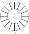
- Figure 4 is a front view of an exemplary tire structure 200 for a non-pneumatic tire not forming part of the present invention.
- the tire structure 200 has a generally annular inner ring 210, a generally annular outer ring 220, and support structure in the form of spokes 230 extending between the inner ring 210 and the outer ring 220.
- spokes 230 extending between the inner ring 210 and the outer ring 220.
- 16 radially extending, linear spokes are shown.
- any number of spokes may be employed in any geometry and orientation.
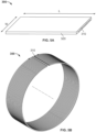
- Figure 5A is a schematic drawing illustrating a perspective view of one embodiment of a reinforced sheet 300.
- the reinforced sheet 300 has a length L in a longitudinal direction, and a width W in a lateral direction. The length L is greater than the width W.
- the sheet 300 may be referred to as an elongated sheet.
- the reinforced sheet 300 includes reinforcement cords 310 extending in a longitudinal direction, and which are embedded in a thermoplastic material 320.
- the reinforcement cords 310 are constructed of a high strength material. Exemplary materials for reinforcement cords 310 include, without limitation, polyester, nylon, aramid, glass, steel, and other metal.
- the thermoplastic material 320 is a thermoplastic elastomer resin.
- An exemplary thermoplastic elastomer resin is commercially sold under the brand name HYTREL by DUPONT. However, it should be understood that any thermoplastic elastomer resin may be employed. Thermoplastic elastomer resins exhibit desirable resilience, heat and chemical resistance, strength, and durability. However, other polymeric materials may be selected to embed the reinforcement cords if different properties are desired.
- the reinforced cords 310 may be embedded in the thermoplastic material 320 through pultrusion, co-extrusion, or other means of cord coating.
- the resulting reinforced sheet 300 would be flexible due to thin gauge and low modulus.
- Figure 5B is a perspective view of the reinforced sheet 300 formed into a hoop.
- the reinforced sheet 300 is bent such that the reinforcement cords 310 extend in a circumferential direction.
- the reinforced sheet may be cut at an angle and the hoop formed such that the reinforcement cords extend at an acute angle with respect to the circumferential direction.
- the ends of the reinforced sheet 300 are joined together. The ends may be joined with an adhesive, or by welding or brazing.
- FIG. 6 is a perspective view of the reinforced sheet 300 disposed on a tire structure 400 for a non-pneumatic tire.
- the tire structure 400 has an inner ring 410 having an axis of rotation, a generally annular outer ring 420, and support structure in the form of an interconnected web extending between the inner ring 410 and the outer ring 420.
- the interconnected web is formed by a plurality of web elements 430 that define polygonal openings.
- the web elements 430 form a plurality of hexagonal and substantially trapezoidal shapes.
- the inner ring 410, outer ring 420, and support structure 430 are constructed of the same material. In alternative embodiments, different materials may be employed.
- the tire structure 400 is merely exemplary, and it should be understood that the reinforced sheet 300 may be disposed about any non-pneumatic tire structure, including structures having webbing and structures having spokes.
- the reinforced sheet 300 is attached to the outer ring 420.
- the reinforced sheet 300 is first formed into a hoop in the manner described above.
- the width of the hoop is substantially the same as the width of the outer ring 420.
- the hoop is attached to the outer ring 420 by spin welding the hoop to the outer ring 420.
- Spin welding is a friction welding technique used on thermoplastic materials, in which the parts to be welded are heated by friction. The heat may be generated by turning the hoop and holding the tire structure 400 stationary against the hoop, or by turning the tire structure 400 and holding the hoop stationary against the tire structure 400. This is continued until the heat of friction between the parts reaches a sufficient level for the parts to weld.
- the stationary part is then released to spin as well, while pressure is applied along the axis of rotation, holding the parts together as they cool.
- Such a process may require the hoop to have a thickness that is greater than a predetermined minimum thickness.
- the hoop is attached to the outer ring with an adhesive, by welding or brazing, or by a chemical bond, such as by heating the components to create a bond.
- the reinforced sheet 300 is a ribbon having a width that is less than the width of the outer ring.
- the elongated sheet may have a greater initial width and the elongated sheet is cut into ribbons having a smaller width.
- the elongated sheet may be initially formed as a ribbon.
- the step of attaching the reinforced sheet 300 to the outer ring 420 of the tire structure 400 includes spirally winding the ribbon about the outer ring 420 of the tire structure 400.
- the ribbon may be affixed to the outer ring 420 with an adhesive, by welding or brazing, or by a chemical bond, such as by heating the components to create a bond.
- the reinforced sheet 300 may be described as being part of the outer ring 420.
- the outer ring 420 may be described as including a lower layer constructed of a first material and an upper layer constructed of a second material different from the first material, wherein the second material has the circumferential reinforcements embedded therein.
- a circumferential tread is disposed about the reinforced sheet 300.
- the circumferential tread may be described as being disposed about the outer ring 420.
- the circumferential tread includes a tread reinforcement layer spaced from a bottom of the circumferential tread. Examples of circumferential treads disposed on reinforced sheets are shown in Figures 7-10 .
- Figure 7 is a schematic drawing illustrating a partial cross-section of one embodiment of a non-pneumatic tire 500.
- the non-pneumatic tire 500 includes the tire structure 400 of Figure 6 , including the inner ring 410, the outer ring 420, and the support structure 430. It should be understood, however, that any tire structure may be employed.
- a reinforced hoop 510 having the same width as the outer ring 420 is disposed about the outer ring 420 in one of the manners described above.
- the reinforced hoop is constructed of one of the materials described above and includes reinforcement cords 520.
- a circumferential tread includes a first elastomeric layer 530 disposed about the reinforced hoop 510.
- the first elastomeric layer may be rubber or any other suitable elastomeric material.
- a tread reinforcement layer 540 having reinforcement cords 550 is disposed above the first elastomeric layer 530.
- Exemplary materials for reinforcement cords 550 include, without limitation, polyester, nylon, aramid, glass, steel, and other metal. Where the reinforcement cords 550 are steel, the reinforcement layer 540 may be referred to as a steel belt. In the illustrated embodiment, the reinforcement layer 540 is a single layer of steel belts. In alternative embodiments, multiple layers of steel belts may be employed.
- the reinforcement cords 550 in the tread reinforcement layer 540 may be constructed of the same material as the reinforcement cords 520 in the reinforced hoop 510, or they may be constructed of different materials.
- the reinforcement cords 550 in the tread reinforcement layer 540 may extend in a circumferential direction, or in a non-circumferential direction, such as at an acute angle with respect to the circumferential direction.
- the tread reinforcement layer 540 includes a skim material that embeds the reinforcement cords.
- the skim material may be the same as the first elastomeric layer 530, or it may be a different material.
- the skim material may be the same material as the reinforced hoop 510.
- the tread reinforcement layer 540 is spaced from the bottom surface of the circumferential tread (and thus spaced from the reinforced hoop 510) by the thickness T of the first elastomeric layer 530.
- the first elastomeric layer 530 has a thickness T of at least 0.5 inches (1.3 cm). In alternative embodiments the first elastomeric layer has a thickness between 0.050 inches (0.13 cm) and 6.5 inches (16.5 cm).
- a second elastomeric layer 560 is disposed above the tread reinforcement layer 540.
- the second elastomeric layer 560 is constructed of the same material as the first elastomeric layer 530.
- the first and second elastomeric layers 530, 540 are constructed of different materials.
- the second elastomeric layer 560 has tread elements formed therein. Exemplary tread elements include, without limitation, grooves, sipes, ribs, blocks, lugs, and other recesses and projections. In an alternative embodiment (not shown), the second elastomeric layer does not include any tread elements.
- a circumferential tread with the first elastomeric layer 530, the tread reinforcement layer 540 and the second elastomeric layer 560 is pre-formed.
- the circumferential tread is then attached to the reinforced hoop 510 with an adhesive, by welding or brazing, or by a chemical bond, such as by heating the components to create a bond.
- the circumferential tread may be built layer by layer onto the reinforced hoop 510.
- the building process would include placing the first elastomeric layer 530 about the reinforced hoop 510, placing the tread reinforcement layer 540 about the first elastomeric layer 530, and placing the second elastomeric layer 560 about the tread reinforcement layer 540.
- the layers are attached to each other at each step, such as with an adhesive, by welding or brazing, or by a chemical bond, such as by heating the components to create a bond.
- the tire is heated after all of the layers are assembled, such that the layers bond to each other.
- the reinforced hoop 510, first elastomeric layer 530, and tread reinforcement layer 540 together form a shear element or shear structure having an elastic region disposed between upper and lower inelastic regions.
- the shear element may help the non-pneumatic tire 500 carry a greater load.
- Figure 8 is a schematic drawing illustrating a partial cross-section of an alternative embodiment of a non-pneumatic tire 600.
- the non-pneumatic tire 600 also includes the tire structure 400 of Figure 6 , including the inner ring 410, the outer ring 420, and the support structure 430. It should be understood, however, that any tire structure may be employed.
- a reinforced hoop 610 having the same width as the outer ring 420 is disposed about the outer ring 420 in one of the manners described above.
- the reinforced hoop is constructed of one of the materials described above and includes reinforcement cords 620.
- a circumferential tread 630 is disposed about the reinforced hoop 610.
- the circumferential tread 630 includes a tread reinforcement layer defined by reinforcement cords 640 embedded therein.
- the reinforcement cords 640 may be the same as the reinforcement cords 550 described above with respect to Figure 7 , including any alternative embodiments discussed above.
- the reinforcement cords 640 are spaced from the bottom surface of the circumferential tread (and thus spaced from the reinforced hoop 510) by the thickness T of the tread material below the reinforcement cords. This thickness may be the same as the thicknesses of the first elastomeric layer 530 described above.
- the reinforced hoop 610, the reinforcement cords 640, and the tread material therebetween form a shear element or shear structure having an elastic region disposed between upper and lower inelastic regions.
- the shear element may help the non-pneumatic tire 500 carry a great load.
- FIG. 9 is a schematic drawing illustrating an alternative embodiment of a shear element formed by a spiral-wrapped ribbon 710 having reinforcement cords 720, a first elastomeric layer 730, and a tread reinforcement layer 740 having reinforcement cords 750.
- a second elastomeric layer 760 is disposed above the tread reinforcement layer 740.
- the Figure 9 embodiment is substantially the same as the Figure 7 embodiment, with the exception of the spiral-wrapped ribbon.
- the alternative embodiments discussed with respect to Figure 7 should thus be understood to also apply to Figure 9 .
- Figure 10 is a schematic drawing illustrating another alternative embodiment of a shear element formed by a spiral-wrapped ribbon 810 having reinforcement cords 820 and a circumferential tread 830 having a tread reinforcement layer 740 embedded therein.
- the Figure 10 embodiment is substantially the same as the Figure 8 embodiment, with the exception of the spiral-wrapped ribbon.
- the alternative embodiments discussed with respect to Figure 8 should thus be understood to also apply to Figure 10 .
Landscapes
- Engineering & Computer Science (AREA)
- Mechanical Engineering (AREA)
- Tires In General (AREA)
Description
- The present invention relates to a non-pneumatic tire, and a method of making the same.
- Various tire constructions have been developed which enable a tire to run in an uninflated or underinflated condition. Non-pneumatic tires do not require inflation, while "run flat tires" may continue to operate after receiving a puncture and a complete or partial loss of pressurized air, for extended periods of time and at relatively high speeds. Non-pneumatic tires may include a plurality of spokes, a webbing, or other support structure that connects an inner ring to an outer ring. In some non-pneumatic tires, a circumferential tread may be wrapped about the outer ring of the tire. The circumferential tread may contain a shear element having an elastic region disposed between upper and lower inelastic regions.
- According to its abstract,
US 4 235 270 A describes a tire having an annular body of resilient elastomeric material with an outer member at the outer periphery which may carry a tread and an inner member at the inner periphery for mounting on a wheel rim. The inner member is supported and cushioned by a plurality of circumferentially spaced-apart wall members extending from the inner member to the outer member. The annular body may have one or more supporting rings and the wall members of adjacent rings as well as the wall members of the same ring may be offset circumferentially of the tire. The wall members provide a lateral spring rate and a variable radial spring rate across the tread of the tire. The wall members, tread, inner member and outer member may be reinforced by cords extending at bias angles or generally circumferentially of the tire. Sidewalls between the inner and outer members may also be provided for low pressure inflation and exclusion of foreign matter from the spaces between the wall members. - According to its abstract,
JP 2009 286208 A - According to its abstract,
JP 2013 032072 A - According to its abstract,
JP 2011 178308 A - According to its abstract,
JP 2008 044445 A - Aspects of the present invention are defined by the appended independent claims. Preferred embodiments of the present invention are defined by the appended dependent claims.
- Described herein is a non-pneumatic tire that includes an inner ring having an axis of rotation and an outer ring having a plurality of circumferential reinforcements. The non-pneumatic tire further includes support structure extending from the inner ring to the outer ring. The non-pneumatic tire also includes a circumferential tread extending about the outer ring. The circumferential tread includes a tread reinforcement layer spaced from a bottom of the circumferential tread.
- Also described herein is a method of making a non-pneumatic tire that includes providing a tire structure having an inner ring, an outer ring, and a plurality of support structures extending between the inner ring and the outer ring. The method further includes providing a thermoplastic sheet having reinforcement cords embedded therein, and attaching the thermoplastic sheet to the outer ring of the tire structure. The method also includes forming a circumferential tread having a reinforcement layer spaced from a bottom surface, and attaching the circumferential tread to the thermoplastic sheet.
- Also described herein is a shear structure for a non-pneumatic tire includes a thermoplastic hoop having reinforcement cords embedded therein. The shear structure also includes a first layer of elastomeric material disposed about the thermoplastic hoop, a reinforcement layer disposed about the first layer of elastomeric material, and a second layer of elastomeric material disposed about the reinforcement layer.
- In the accompanying drawings, structures are illustrated that, together with the detailed description provided below, describe exemplary embodiments of the claimed invention. Like elements are identified with the same reference numerals. It should be understood that elements shown as a single component may be replaced with multiple components, and elements shown as multiple components may be replaced with a single component. The drawings are not to scale and the proportion of certain elements may be exaggerated for the purpose of illustration.
-
Figure 1 is a front view of an undeformed non-pneumatic tire; -
Figure 2 is a front view of the non-pneumatic tire ofFigure 1 being deformed when subjected to a load; -
Figure 3 is a front view of an alternative embodiment of a tire structure for a non-pneumatic tire; -
Figure 4 is a front view of an exemplary tire structure for a non-pneumatic tire not forming part of the present invention; -
Figure 5A is a schematic drawing illustrating a perspective view of one embodiment of a reinforced sheet; -
Figure 5B is a perspective view of the reinforced sheet formed into a hoop; -
Figure 6 is a perspective view of the reinforced sheet disposed on a tire structure for a non-pneumatic tire; -
Figure 7 is a schematic drawing illustrating a partial cross-section of one embodiment of a non-pneumatic tire; -
Figure 8 is a schematic drawing illustrating a partial cross-section of an alternative embodiment of a non-pneumatic tire; -
Figure 9 is a schematic drawing illustrating an alternative embodiment of a shear element formed by a reinforced spiral ribbon and a circumferential tread; and -
Figure 10 is a schematic drawing illustrating another alternative embodiment of a shear element formed by a reinforced spiral ribbon and a circumferential tread. -
Figures 1 and 2 illustrate one embodiment of a non-pneumatictire 10. Thenon-pneumatic tire 10 is merely an exemplary illustration and is not intended to be limiting. In the illustrated embodiment, thenon-pneumatic tire 10 includes a generally annularinner ring 20 that engages a rim (not shown) to which thetire 10 is mounted. The generally annularinner ring 20 has aninternal surface 23 and anexternal surface 24 and can be made of an elastomeric material or metal. - The
non-pneumatic tire 10 further includes a generally annularouter ring 30 surrounding an interconnected web 40, which is a support structure connected to the generally annularinner ring 20. In alternative embodiments, a plurality of spokes or other support structure connects the inner ring to the outer ring. Theouter ring 30 can be configured to deform in anarea 48 around and including a footprint region 32 (seeFigure 2 ), which decreases vibration and increases ride comfort. - In one embodiment, the generally annular
inner ring 20 and the generally annularouter ring 30 are made of the same material as interconnected web 40. In an alternative embodiment, at least one of the generally annular inner ring, the generally annular outer ring, and the interconnected web are made of a different material. As shown inFigure 1 , the generally annularouter ring 30 can have a radiallyexternal surface 34 to which atread carrying layer 70 is attached. Attachment can be done adhesively or using other methods commonly available in the art. - In the illustrated embodiment, the interconnected web 40 has at least two radially
adjacent layers 56, 58 of web elements 42 that define a plurality of generallypolygonal openings 50. In other embodiments (not shown), other web configurations may be employed. In another embodiment (not shown), spokes or other support structure may be employed instead of a web. -
Figure 3 illustrates a front view of another embodiment of atire structure 100 for a non-pneumatic tire. Thetire structure 100 has a generally annularinner ring 110, a generally annularouter ring 120, and support structure in the form of an interconnected web extending between theinner ring 110 and theouter ring 120. The interconnected web is formed by a plurality ofweb elements 130 that define polygonal openings. In this particular embodiment, theweb elements 130 form a plurality of hexagonal and substantially trapezoidal shapes, including an outer series of alternating hexagonal and trapezoidal opening and an inner series of alternating hexagonal and trapezoidal openings. -
Figure 4 is a front view of anexemplary tire structure 200 for a non-pneumatic tire not forming part of the present invention. Thetire structure 200 has a generally annularinner ring 210, a generally annularouter ring 220, and support structure in the form ofspokes 230 extending between theinner ring 210 and theouter ring 220. In the illustrated embodiment, 16 radially extending, linear spokes are shown. However, it should be understood that any number of spokes may be employed in any geometry and orientation. It should be understood that the geometries shown inFigures 1-4 are merely exemplary and that any geometries may be employed.
Figure 5A is a schematic drawing illustrating a perspective view of one embodiment of a reinforcedsheet 300. The reinforcedsheet 300 has a length L in a longitudinal direction, and a width W in a lateral direction. The length L is greater than the width W. Thus, thesheet 300 may be referred to as an elongated sheet. - In one embodiment, the reinforced
sheet 300 includesreinforcement cords 310 extending in a longitudinal direction, and which are embedded in athermoplastic material 320. Thereinforcement cords 310 are constructed of a high strength material. Exemplary materials forreinforcement cords 310 include, without limitation, polyester, nylon, aramid, glass, steel, and other metal. In one specific embodiment, thethermoplastic material 320 is a thermoplastic elastomer resin. An exemplary thermoplastic elastomer resin is commercially sold under the brand name HYTREL by DUPONT. However, it should be understood that any thermoplastic elastomer resin may be employed. Thermoplastic elastomer resins exhibit desirable resilience, heat and chemical resistance, strength, and durability. However, other polymeric materials may be selected to embed the reinforcement cords if different properties are desired. - The reinforced
cords 310 may be embedded in thethermoplastic material 320 through pultrusion, co-extrusion, or other means of cord coating. The resulting reinforcedsheet 300 would be flexible due to thin gauge and low modulus. -
Figure 5B is a perspective view of the reinforcedsheet 300 formed into a hoop. The reinforcedsheet 300 is bent such that thereinforcement cords 310 extend in a circumferential direction. In an alternative embodiment (not shown), the reinforced sheet may be cut at an angle and the hoop formed such that the reinforcement cords extend at an acute angle with respect to the circumferential direction. After the hoop is formed, the ends of the reinforcedsheet 300 are joined together. The ends may be joined with an adhesive, or by welding or brazing. -
Figure 6 is a perspective view of the reinforcedsheet 300 disposed on atire structure 400 for a non-pneumatic tire. Thetire structure 400 has aninner ring 410 having an axis of rotation, a generally annularouter ring 420, and support structure in the form of an interconnected web extending between theinner ring 410 and theouter ring 420. The interconnected web is formed by a plurality ofweb elements 430 that define polygonal openings. In this particular embodiment, theweb elements 430 form a plurality of hexagonal and substantially trapezoidal shapes. In one embodiment, theinner ring 410,outer ring 420, andsupport structure 430 are constructed of the same material. In alternative embodiments, different materials may be employed. Thetire structure 400 is merely exemplary, and it should be understood that the reinforcedsheet 300 may be disposed about any non-pneumatic tire structure, including structures having webbing and structures having spokes. - The reinforced
sheet 300 is attached to theouter ring 420. In the illustrated embodiment, the reinforcedsheet 300 is first formed into a hoop in the manner described above. The width of the hoop is substantially the same as the width of theouter ring 420. In one embodiment, the hoop is attached to theouter ring 420 by spin welding the hoop to theouter ring 420. Spin welding is a friction welding technique used on thermoplastic materials, in which the parts to be welded are heated by friction. The heat may be generated by turning the hoop and holding thetire structure 400 stationary against the hoop, or by turning thetire structure 400 and holding the hoop stationary against thetire structure 400. This is continued until the heat of friction between the parts reaches a sufficient level for the parts to weld. The stationary part is then released to spin as well, while pressure is applied along the axis of rotation, holding the parts together as they cool. Such a process may require the hoop to have a thickness that is greater than a predetermined minimum thickness. In alternative embodiments, the hoop is attached to the outer ring with an adhesive, by welding or brazing, or by a chemical bond, such as by heating the components to create a bond. - In an alternative embodiment, the reinforced
sheet 300 is a ribbon having a width that is less than the width of the outer ring. In such an embodiment, the elongated sheet may have a greater initial width and the elongated sheet is cut into ribbons having a smaller width. Alternatively, the elongated sheet may be initially formed as a ribbon. - When the reinforced
sheet 300 is formed as a ribbon, the step of attaching the reinforcedsheet 300 to theouter ring 420 of thetire structure 400 includes spirally winding the ribbon about theouter ring 420 of thetire structure 400. The ribbon may be affixed to theouter ring 420 with an adhesive, by welding or brazing, or by a chemical bond, such as by heating the components to create a bond. - After the reinforced
sheet 300 is attached to theouter ring 420, the reinforcedsheet 300 may be described as being part of theouter ring 420. In other words, theouter ring 420 may be described as including a lower layer constructed of a first material and an upper layer constructed of a second material different from the first material, wherein the second material has the circumferential reinforcements embedded therein. - After the reinforced
sheet 300 is attached to the outer ring, a circumferential tread is disposed about the reinforcedsheet 300. Where the reinforcedsheet 300 is described as being part of theouter ring 420, the circumferential tread may be described as being disposed about theouter ring 420. In one embodiment, the circumferential tread includes a tread reinforcement layer spaced from a bottom of the circumferential tread. Examples of circumferential treads disposed on reinforced sheets are shown inFigures 7-10 . -
Figure 7 is a schematic drawing illustrating a partial cross-section of one embodiment of anon-pneumatic tire 500. In this embodiment, thenon-pneumatic tire 500 includes thetire structure 400 ofFigure 6 , including theinner ring 410, theouter ring 420, and thesupport structure 430. It should be understood, however, that any tire structure may be employed. - A reinforced
hoop 510 having the same width as theouter ring 420 is disposed about theouter ring 420 in one of the manners described above. The reinforced hoop is constructed of one of the materials described above and includesreinforcement cords 520. - A circumferential tread includes a first
elastomeric layer 530 disposed about the reinforcedhoop 510. The first elastomeric layer may be rubber or any other suitable elastomeric material. Atread reinforcement layer 540 havingreinforcement cords 550 is disposed above the firstelastomeric layer 530. Exemplary materials forreinforcement cords 550 include, without limitation, polyester, nylon, aramid, glass, steel, and other metal. Where thereinforcement cords 550 are steel, thereinforcement layer 540 may be referred to as a steel belt. In the illustrated embodiment, thereinforcement layer 540 is a single layer of steel belts. In alternative embodiments, multiple layers of steel belts may be employed. Thereinforcement cords 550 in thetread reinforcement layer 540 may be constructed of the same material as thereinforcement cords 520 in the reinforcedhoop 510, or they may be constructed of different materials. Thereinforcement cords 550 in thetread reinforcement layer 540 may extend in a circumferential direction, or in a non-circumferential direction, such as at an acute angle with respect to the circumferential direction. - In the illustrated embodiment, the
tread reinforcement layer 540 includes a skim material that embeds the reinforcement cords. The skim material may be the same as the firstelastomeric layer 530, or it may be a different material. For example, the skim material may be the same material as the reinforcedhoop 510. - The
tread reinforcement layer 540 is spaced from the bottom surface of the circumferential tread (and thus spaced from the reinforced hoop 510) by the thickness T of the firstelastomeric layer 530. In one embodiment, the firstelastomeric layer 530 has a thickness T of at least 0.5 inches (1.3 cm). In alternative embodiments the first elastomeric layer has a thickness between 0.050 inches (0.13 cm) and 6.5 inches (16.5 cm). - A second
elastomeric layer 560 is disposed above thetread reinforcement layer 540. In one embodiment, the secondelastomeric layer 560 is constructed of the same material as the firstelastomeric layer 530. In an alternative embodiment, the first and secondelastomeric layers elastomeric layer 560 has tread elements formed therein. Exemplary tread elements include, without limitation, grooves, sipes, ribs, blocks, lugs, and other recesses and projections. In an alternative embodiment (not shown), the second elastomeric layer does not include any tread elements. - In one embodiment, a circumferential tread with the first
elastomeric layer 530, thetread reinforcement layer 540 and the secondelastomeric layer 560 is pre-formed. The circumferential tread is then attached to the reinforcedhoop 510 with an adhesive, by welding or brazing, or by a chemical bond, such as by heating the components to create a bond. - In an alternative embodiment, the circumferential tread may be built layer by layer onto the reinforced
hoop 510. The building process would include placing the firstelastomeric layer 530 about the reinforcedhoop 510, placing thetread reinforcement layer 540 about the firstelastomeric layer 530, and placing the secondelastomeric layer 560 about thetread reinforcement layer 540. In one embodiment, the layers are attached to each other at each step, such as with an adhesive, by welding or brazing, or by a chemical bond, such as by heating the components to create a bond. In an alternative embodiment, the tire is heated after all of the layers are assembled, such that the layers bond to each other. - The reinforced
hoop 510, firstelastomeric layer 530, and treadreinforcement layer 540 together form a shear element or shear structure having an elastic region disposed between upper and lower inelastic regions. The shear element may help thenon-pneumatic tire 500 carry a greater load. -
Figure 8 is a schematic drawing illustrating a partial cross-section of an alternative embodiment of anon-pneumatic tire 600. In this embodiment, thenon-pneumatic tire 600 also includes thetire structure 400 ofFigure 6 , including theinner ring 410, theouter ring 420, and thesupport structure 430. It should be understood, however, that any tire structure may be employed. - A reinforced
hoop 610 having the same width as theouter ring 420 is disposed about theouter ring 420 in one of the manners described above. The reinforced hoop is constructed of one of the materials described above and includesreinforcement cords 620. - A
circumferential tread 630 is disposed about the reinforcedhoop 610. Thecircumferential tread 630 includes a tread reinforcement layer defined byreinforcement cords 640 embedded therein. Thereinforcement cords 640 may be the same as thereinforcement cords 550 described above with respect toFigure 7 , including any alternative embodiments discussed above. - The
reinforcement cords 640 are spaced from the bottom surface of the circumferential tread (and thus spaced from the reinforced hoop 510) by the thickness T of the tread material below the reinforcement cords. This thickness may be the same as the thicknesses of the firstelastomeric layer 530 described above. - The reinforced
hoop 610, thereinforcement cords 640, and the tread material therebetween form a shear element or shear structure having an elastic region disposed between upper and lower inelastic regions. The shear element may help thenon-pneumatic tire 500 carry a great load. - The shear element may be formed in other ways. For example,
Figure 9 is a schematic drawing illustrating an alternative embodiment of a shear element formed by a spiral-wrappedribbon 710 havingreinforcement cords 720, a firstelastomeric layer 730, and atread reinforcement layer 740 havingreinforcement cords 750. A secondelastomeric layer 760 is disposed above thetread reinforcement layer 740. TheFigure 9 embodiment is substantially the same as theFigure 7 embodiment, with the exception of the spiral-wrapped ribbon. The alternative embodiments discussed with respect toFigure 7 should thus be understood to also apply toFigure 9 . -
Figure 10 is a schematic drawing illustrating another alternative embodiment of a shear element formed by a spiral-wrappedribbon 810 havingreinforcement cords 820 and acircumferential tread 830 having atread reinforcement layer 740 embedded therein. TheFigure 10 embodiment is substantially the same as theFigure 8 embodiment, with the exception of the spiral-wrapped ribbon. The alternative embodiments discussed with respect toFigure 8 should thus be understood to also apply toFigure 10 . - To the extent that the term "includes" or "including" is used in the specification or the claims, it is intended to be inclusive in a manner similar to the term "comprising" as that term is interpreted when employed as a transitional word in a claim. Furthermore, to the extent that the term "or" is employed (e.g., A or B) it is intended to mean "A or B or both." When the applicants intend to indicate "only A or B but not both" then the term "only A or B but not both" will be employed. Thus, use of the term "or" herein is the inclusive, and not the exclusive use. See, Bryan A. Garner, A Dictionary of Modern Legal Usage 624 (2d. Ed. 1995). Also, to the extent that the terms "in" or "into" are used in the specification or the claims, it is intended to additionally mean "on" or "onto." Furthermore, to the extent the term "connect" is used in the specification or claims, it is intended to mean not only "directly connected to," but also "indirectly connected to" such as connected through another component or components.
- While the present application has been illustrated by the description of embodiments thereof, and while the embodiments have been described in considerable detail, it is not the intention of the applicants to restrict or in any way limit the scope of the appended claims to such detail. Additional advantages and modifications will readily appear to those skilled in the art. Therefore, the application, in its broader aspects, is not limited to the specific details, the representative apparatus and method, and illustrative examples shown and described.
Claims (13)
- A non-pneumatic tire (10; 500; 600; 700; 800) comprising:an inner ring (20; 110; 210; 410) having an axis of rotation;an outer ring (30; 120; 220; 420);a reinforced sheet (300) attached to a radially outer surface of the outer ring (420),wherein the reinforced sheet (300) has a length (L) in a longitudinal direction, which longitudinal direction corresponds to the circumferential direction of the non-pneumatic tire, and a width (W) in a lateral direction,wherein the length (L) is greater than the width (W),wherein the reinforced sheet (300) is a sheet of thermoplastic material (320) having a plurality of reinforcement cords (310) constructed of a high strength material embedded therein and extending in a tire circumferential direction,wherein the outer ring (30; 120; 220; 420) is constructed of a material different from the thermoplastic material (320);a support structure (40; 130; 230; 430) extending from the inner ring (20; 110; 210; 410) to the outer ring (30; 120; 220; 420), wherein the support structure (430) is in the form of an interconnected web extending between the inner ring (410) and the outer ring (420); anda circumferential tread (70) extending about the outer ring (30; 120; 220; 420), the circumferential tread (70) including a tread reinforcement layer (540; 640; 740; 840) spaced from a bottom of the circumferential tread (70),characterised in thatthe interconnected web is formed by a plurality of web elements (430) that define a plurality of hexagonal and substantially trapezoidal shaped openings.
- The non-pneumatic tire (10; 500; 600; 700; 800) of claim 1, wherein the inner ring (20; 110; 210; 410) and the support structure (40; 130; 230; 430) are constructed of a first material.
- The non-pneumatic tire (10; 500; 600; 700; 800) of any one of claims 1 or 2, wherein the reinforced sheet (300) and the tread reinforcement layer (540) are constructed of a same material.
- The non-pneumatic tire (10; 500; 600; 700; 800) of any one of claims 1 to 3, wherein the circumferential tread (70) includes a lower elastomeric layer (530; 630; 730; 830) with a thickness of at least 0.5 inches (1.3 cm) disposed below the tread reinforcement layer (540; 640; 740; 840), and an upper elastomeric layer (560; 760) disposed above the tread reinforcement layer (540; 640; 740; 840).
- The non-pneumatic tire (10; 500; 600; 700; 800) of any one of claims 1 to 4, wherein the tread reinforcement layer (540; 640; 740; 840) is a single layer of steel belts.
- The non-pneumatic tire (10; 500; 600; 700; 800) of claim 5, wherein the steel belts extend in a non-circumferential direction.
- The non-pneumatic tire (10; 500; 600; 700; 800) of any one of claims 1 to 6, wherein the support structure (40; 130; 230; 430) is a webbing (40; 130; 430).
- A method of making a non-pneumatic tire (10; 500; 600; 700; 800) of any one of claims 1 to 7, the method comprising:providing a tire structure (100; 200; 400) including an inner ring (20; 110; 210; 410), an outer ring (30; 120; 220; 420), and a plurality of support structures (40; 130; 230; 430) extending between the inner ring (20; 110; 210; 410) and the outer ring (30; 120; 220; 420);providing a thermoplastic sheet (300; 510; 610; 710; 810) having reinforcement cords (310; 520; 620; 720; 820) embedded therein, wherein the outer ring (30; 120; 220; 420) is constructed of a material different from the thermoplastic sheet (300; 510; 610; 710; 810);attaching the thermoplastic sheet (300; 510; 610; 710; 810) to the outer ring (30; 120; 220; 420) of the tire structure (100; 200; 400);forming a circumferential tread (70) having a reinforcement layer (540; 640; 740; 840) spaced from a bottom surface; andattaching the circumferential tread (70) to the thermoplastic sheet (300; 510; 610; 710; 810).
- The method of claim 8, wherein the providing of the thermoplastic sheet (300; 510; 610; 710; 810) having reinforcement cords (310; 520; 620; 720; 820) embedded therein includes coating a plurality of reinforcement cords (310; 520; 620; 720; 820) with a thermoplastic material through one of a pultrusion process and an extrusion process.
- The method of claim 8 or claim 9, wherein the thermoplastic sheet (300; 510; 610; 710; 810) is an elongated thermoplastic ribbon (710; 810), and wherein the attaching of the thermoplastic sheet (300; 510; 610; 710; 810) to the outer ring (30; 120; 220; 420) of the tire structure (100; 200; 400) includes spirally winding the elongated thermoplastic ribbon (710; 810) about the outer ring (30; 120; 220; 420) of the tire structure (100; 200; 400).
- The method of any one of claims 8 to 10, wherein the attaching of the thermoplastic sheet (300; 510; 610; 710; 810) to the outer ring (30; 120; 220; 420) of the tire structure (100; 200; 400) includes forming a hoop and joining a first end of the thermoplastic sheet (300; 510; 610; 710; 810) to a second end of the thermoplastic sheet (300; 510; 610; 710; 810).
- The method of claim 11, wherein the attaching of the thermoplastic sheet (300; 510; 610; 710; 810) to the outer ring (30; 120; 220; 420) of the tire structure (100; 200; 400) further includes spin welding the hoop to the outer ring (30; 120; 220; 420).
- The method of any one of claims 8 to 12, wherein the forming of the circumferential tread (70) and the attaching of the circumferential tread (70) to the thermoplastic sheet (300; 510; 610; 710; 810) includes placing a first elastomeric layer (530; 630; 730; 830) about the thermoplastic sheet (300; 510; 610; 710; 810), placing the reinforcement layer (540; 640; 740; 840) about the first elastomeric layer (530; 630; 730; 830), and placing a second elastomeric layer (560; 760) about the reinforcement layer (540; 640; 740; 840).
Applications Claiming Priority (2)
| Application Number | Priority Date | Filing Date | Title |
|---|---|---|---|
| US201862785792P | 2018-12-28 | 2018-12-28 | |
| PCT/US2019/066828 WO2020139623A1 (en) | 2018-12-28 | 2019-12-17 | Non-pneumatic tire having reinforced outer ring |
Publications (3)
| Publication Number | Publication Date |
|---|---|
| EP3902691A1 EP3902691A1 (en) | 2021-11-03 |
| EP3902691A4 EP3902691A4 (en) | 2022-10-19 |
| EP3902691B1 true EP3902691B1 (en) | 2025-04-23 |
Family
ID=71128916
Family Applications (1)
| Application Number | Title | Priority Date | Filing Date |
|---|---|---|---|
| EP19906197.9A Active EP3902691B1 (en) | 2018-12-28 | 2019-12-17 | Non-pneumatic tire having reinforced outer ring |
Country Status (5)
| Country | Link |
|---|---|
| US (1) | US12090801B2 (en) |
| EP (1) | EP3902691B1 (en) |
| JP (1) | JP7275281B2 (en) |
| CN (1) | CN113226793A (en) |
| WO (1) | WO2020139623A1 (en) |
Families Citing this family (5)
| Publication number | Priority date | Publication date | Assignee | Title |
|---|---|---|---|---|
| US12605966B2 (en) | 2020-12-18 | 2026-04-21 | Bridgestone Americas Tire Operations, Llc | Non-pneumatic tire with fiber metal laminate construction |
| CN116648361A (en) * | 2020-12-29 | 2023-08-25 | 普利司通美国轮胎运营有限责任公司 | Tire belts with filaments with non-circular cross-section |
| KR102746032B1 (en) * | 2022-01-13 | 2024-12-24 | 한국타이어앤테크놀로지 주식회사 | A non-pneumatic tire |
| US20250206064A1 (en) * | 2023-12-21 | 2025-06-26 | The Goodyear Tire & Rubber Company | Shearband with oblong cords for non-pneumatic tires |
| DE102024204897A1 (en) * | 2024-05-27 | 2025-11-27 | Continental Reifen Deutschland Gmbh | Vehicle tires with ring reinforcement |
Family Cites Families (35)
| Publication number | Priority date | Publication date | Assignee | Title |
|---|---|---|---|---|
| US4235270A (en) | 1978-06-30 | 1980-11-25 | The Goodyear Tire & Rubber Company | Tire with supporting and cushioning walls |
| US4514243A (en) | 1982-07-09 | 1985-04-30 | Dan T. Moore Co. | Tire for wheelchairs and the like |
| DE59403348D1 (en) * | 1993-04-28 | 1997-08-21 | Continental Ag | Solid tires |
| US6303060B1 (en) * | 1997-10-20 | 2001-10-16 | Pacific Circle Technologies, Inc. | Method of making non-deflatable tire and wheel assembly |
| FR2787388B1 (en) | 1998-12-18 | 2001-01-12 | Conception & Dev Michelin Sa | ELASTIC BANDAGE THAT CAN BE USED NON-PNEUMATICALLY |
| CA2356724C (en) * | 2000-09-06 | 2009-08-11 | George Tunis | Wire reinforced thermoplastic coating |
| JP4465916B2 (en) | 2001-05-09 | 2010-05-26 | 横浜ゴム株式会社 | Pneumatic tire using thermoplastic elastomer-coated steel cord |
| DE60238610D1 (en) * | 2001-07-19 | 2011-01-27 | Pirelli | TIRES FOR MOTOR VEHICLES WITH WAVY MONOFILAMENTS IN BELT REINFORCEMENT LAYER |
| JP2004224117A (en) * | 2003-01-21 | 2004-08-12 | Yokohama Rubber Co Ltd:The | Tire/wheel assembly and pneumatic tire |
| CA2525982C (en) | 2005-10-27 | 2011-07-26 | Michelin Recherche Et Technique S.A. | Non-pneumatic tire |
| JP3952211B1 (en) | 2006-08-11 | 2007-08-01 | 横浜ゴム株式会社 | Non pneumatic tire |
| WO2009016962A1 (en) | 2007-07-31 | 2009-02-05 | Toyo Tire & Rubber Co., Ltd. | Non-pneumatic tire, and its manufacturing method |
| JP5225743B2 (en) | 2008-04-30 | 2013-07-03 | 東洋ゴム工業株式会社 | Non-pneumatic tire |
| JP2009286208A (en) * | 2008-05-28 | 2009-12-10 | Yokohama Rubber Co Ltd:The | Non-pneumatic tire |
| US20110253279A1 (en) * | 2008-12-22 | 2011-10-20 | Guido Luigi Daghini | Tyre reinforced with steel cords comprising fine filaments |
| JP5314621B2 (en) | 2010-03-02 | 2013-10-16 | 東洋ゴム工業株式会社 | Non-pneumatic tire |
| JP5394304B2 (en) | 2010-04-12 | 2014-01-22 | 東洋ゴム工業株式会社 | Non-pneumatic tire and manufacturing method thereof |
| JP5774406B2 (en) | 2011-08-01 | 2015-09-09 | 東洋ゴム工業株式会社 | Non-pneumatic tire |
| US8931531B2 (en) | 2012-05-18 | 2015-01-13 | The Goodyear Tire & Rubber Company | System for non-pneumatic support of a vehicle |
| CN104508194A (en) * | 2012-05-21 | 2015-04-08 | 株式会社普利司通 | Cord, rubber-cord composite structure, and tire |
| JP5541348B2 (en) | 2012-11-27 | 2014-07-09 | 横浜ゴム株式会社 | Non-pneumatic tire |
| DE102013201842B4 (en) * | 2013-02-05 | 2024-07-18 | Action Composites GmbH | Wheel made of fibre composite material and manufacturing process |
| JP6291489B2 (en) * | 2013-05-22 | 2018-03-14 | 住友ゴム工業株式会社 | AIRLESS TIRE AND MANUFACTURING METHOD THEREOF |
| EP3086948B1 (en) * | 2013-12-24 | 2020-03-11 | Bridgestone Americas Tire Operations, LLC | Airless tire construction having variable stiffness |
| WO2016099476A1 (en) * | 2014-12-17 | 2016-06-23 | Compagnie Generale Des Etablissements Michelin | Method and apparatus for molding non-pneumatic wheels |
| EP3064371B1 (en) | 2015-03-05 | 2020-04-29 | Sumitomo Rubber Industries, Ltd. | Airless tire |
| JP6408937B2 (en) | 2015-03-05 | 2018-10-17 | 住友ゴム工業株式会社 | Airless tire |
| JP6487779B2 (en) | 2015-06-01 | 2019-03-20 | 住友ゴム工業株式会社 | Airless tire |
| JP6618693B2 (en) | 2015-03-18 | 2019-12-11 | 株式会社ブリヂストン | Non pneumatic tire |
| JP6689029B2 (en) * | 2015-03-24 | 2020-04-28 | 株式会社ブリヂストン | Non-pneumatic tire |
| FR3036651B1 (en) | 2015-05-28 | 2017-05-19 | Michelin & Cie | MULTI-COMPOSITE FLAT REINFORCEMENT |
| JP6613716B2 (en) * | 2015-08-24 | 2019-12-04 | 住友ゴム工業株式会社 | Airless tire |
| DE102015117434B3 (en) * | 2015-10-13 | 2017-02-02 | Oke Group Gmbh | Inline method for producing a slat profile for a slatted frame |
| JP2018058541A (en) | 2016-10-07 | 2018-04-12 | 東洋ゴム工業株式会社 | Non-pneumatic tire and manufacturing method of the same |
| JP6498731B2 (en) | 2017-08-02 | 2019-04-10 | コンパニー ゼネラール デ エタブリッスマン ミシュラン | Shear band with interlaced reinforcement |
-
2019
- 2019-12-17 CN CN201980085887.XA patent/CN113226793A/en active Pending
- 2019-12-17 US US17/297,537 patent/US12090801B2/en active Active
- 2019-12-17 WO PCT/US2019/066828 patent/WO2020139623A1/en not_active Ceased
- 2019-12-17 JP JP2021537169A patent/JP7275281B2/en active Active
- 2019-12-17 EP EP19906197.9A patent/EP3902691B1/en active Active
Also Published As
| Publication number | Publication date |
|---|---|
| JP2022515815A (en) | 2022-02-22 |
| US12090801B2 (en) | 2024-09-17 |
| JP7275281B2 (en) | 2023-05-17 |
| EP3902691A4 (en) | 2022-10-19 |
| US20220041015A1 (en) | 2022-02-10 |
| CN113226793A (en) | 2021-08-06 |
| EP3902691A1 (en) | 2021-11-03 |
| WO2020139623A1 (en) | 2020-07-02 |
Similar Documents
| Publication | Publication Date | Title |
|---|---|---|
| EP3902691B1 (en) | Non-pneumatic tire having reinforced outer ring | |
| EP3615351B1 (en) | Tire with spoke loops | |
| EP3519204B1 (en) | Reinforced rubber spoke for a tire | |
| CN108068549B (en) | Non-inflatable support structure | |
| EP3558696B1 (en) | Method of mounting a non-pneumatic tire onto a hub | |
| US20240399793A1 (en) | Flexible metallic web elements for non-pneumatic tire | |
| EP3694729B1 (en) | Non-pneumatic tire with web having variable thickness | |
| EP3558694B1 (en) | Non-pneumatic wheel and hub | |
| EP3902690B1 (en) | Non-pneumatic tire having reinforced support structure | |
| JP7248540B2 (en) | Method for manufacturing non-pneumatic tires | |
| US6420005B1 (en) | Band element for pneumatic tire | |
| US11833866B2 (en) | Web structure for non-pneumatic tire and method of making same | |
| EP4271574B1 (en) | Tire band with filaments having a non-circular cross section | |
| EP4084966B1 (en) | Non-pneumatic tire having molded sidewall cover | |
| WO2021123901A1 (en) | Non-pneumatic wheel | |
| CN118524940A (en) | System and method for manufacturing a belt and tread assembly for a non-pneumatic tire |
Legal Events
| Date | Code | Title | Description |
|---|---|---|---|
| STAA | Information on the status of an ep patent application or granted ep patent |
Free format text: STATUS: THE INTERNATIONAL PUBLICATION HAS BEEN MADE |
|
| PUAI | Public reference made under article 153(3) epc to a published international application that has entered the european phase |
Free format text: ORIGINAL CODE: 0009012 |
|
| STAA | Information on the status of an ep patent application or granted ep patent |
Free format text: STATUS: REQUEST FOR EXAMINATION WAS MADE |
|
| 17P | Request for examination filed |
Effective date: 20210712 |
|
| AK | Designated contracting states |
Kind code of ref document: A1 Designated state(s): AL AT BE BG CH CY CZ DE DK EE ES FI FR GB GR HR HU IE IS IT LI LT LU LV MC MK MT NL NO PL PT RO RS SE SI SK SM TR |
|
| DAV | Request for validation of the european patent (deleted) | ||
| DAX | Request for extension of the european patent (deleted) | ||
| A4 | Supplementary search report drawn up and despatched |
Effective date: 20220919 |
|
| RIC1 | Information provided on ipc code assigned before grant |
Ipc: B60C 7/14 20060101ALI20220913BHEP Ipc: B60C 11/00 20060101ALI20220913BHEP Ipc: B60C 7/10 20060101AFI20220913BHEP |
|
| STAA | Information on the status of an ep patent application or granted ep patent |
Free format text: STATUS: EXAMINATION IS IN PROGRESS |
|
| 17Q | First examination report despatched |
Effective date: 20231031 |
|
| GRAP | Despatch of communication of intention to grant a patent |
Free format text: ORIGINAL CODE: EPIDOSNIGR1 |
|
| STAA | Information on the status of an ep patent application or granted ep patent |
Free format text: STATUS: GRANT OF PATENT IS INTENDED |
|
| INTG | Intention to grant announced |
Effective date: 20250109 |
|
| GRAS | Grant fee paid |
Free format text: ORIGINAL CODE: EPIDOSNIGR3 |
|
| GRAA | (expected) grant |
Free format text: ORIGINAL CODE: 0009210 |
|
| STAA | Information on the status of an ep patent application or granted ep patent |
Free format text: STATUS: THE PATENT HAS BEEN GRANTED |
|
| P01 | Opt-out of the competence of the unified patent court (upc) registered |
Free format text: CASE NUMBER: APP_8171/2025 Effective date: 20250218 |
|
| AK | Designated contracting states |
Kind code of ref document: B1 Designated state(s): AL AT BE BG CH CY CZ DE DK EE ES FI FR GB GR HR HU IE IS IT LI LT LU LV MC MK MT NL NO PL PT RO RS SE SI SK SM TR |
|
| REG | Reference to a national code |
Ref country code: GB Ref legal event code: FG4D |
|
| REG | Reference to a national code |
Ref country code: CH Ref legal event code: EP |
|
| REG | Reference to a national code |
Ref country code: DE Ref legal event code: R096 Ref document number: 602019069174 Country of ref document: DE |
|
| REG | Reference to a national code |
Ref country code: IE Ref legal event code: FG4D |
|
| REG | Reference to a national code |
Ref country code: NL Ref legal event code: MP Effective date: 20250423 |
|
| PG25 | Lapsed in a contracting state [announced via postgrant information from national office to epo] |
Ref country code: NL Free format text: LAPSE BECAUSE OF FAILURE TO SUBMIT A TRANSLATION OF THE DESCRIPTION OR TO PAY THE FEE WITHIN THE PRESCRIBED TIME-LIMIT Effective date: 20250423 |
|
| REG | Reference to a national code |
Ref country code: AT Ref legal event code: MK05 Ref document number: 1787442 Country of ref document: AT Kind code of ref document: T Effective date: 20250423 |
|
| PG25 | Lapsed in a contracting state [announced via postgrant information from national office to epo] |
Ref country code: PT Free format text: LAPSE BECAUSE OF FAILURE TO SUBMIT A TRANSLATION OF THE DESCRIPTION OR TO PAY THE FEE WITHIN THE PRESCRIBED TIME-LIMIT Effective date: 20250825 Ref country code: ES Free format text: LAPSE BECAUSE OF FAILURE TO SUBMIT A TRANSLATION OF THE DESCRIPTION OR TO PAY THE FEE WITHIN THE PRESCRIBED TIME-LIMIT Effective date: 20250423 Ref country code: FI Free format text: LAPSE BECAUSE OF FAILURE TO SUBMIT A TRANSLATION OF THE DESCRIPTION OR TO PAY THE FEE WITHIN THE PRESCRIBED TIME-LIMIT Effective date: 20250423 |
|
| REG | Reference to a national code |
Ref country code: LT Ref legal event code: MG9D |
|
| PG25 | Lapsed in a contracting state [announced via postgrant information from national office to epo] |
Ref country code: NO Free format text: LAPSE BECAUSE OF FAILURE TO SUBMIT A TRANSLATION OF THE DESCRIPTION OR TO PAY THE FEE WITHIN THE PRESCRIBED TIME-LIMIT Effective date: 20250723 Ref country code: GR Free format text: LAPSE BECAUSE OF FAILURE TO SUBMIT A TRANSLATION OF THE DESCRIPTION OR TO PAY THE FEE WITHIN THE PRESCRIBED TIME-LIMIT Effective date: 20250724 |
|
| PG25 | Lapsed in a contracting state [announced via postgrant information from national office to epo] |
Ref country code: PL Free format text: LAPSE BECAUSE OF FAILURE TO SUBMIT A TRANSLATION OF THE DESCRIPTION OR TO PAY THE FEE WITHIN THE PRESCRIBED TIME-LIMIT Effective date: 20250423 |
|
| PG25 | Lapsed in a contracting state [announced via postgrant information from national office to epo] |
Ref country code: BG Free format text: LAPSE BECAUSE OF FAILURE TO SUBMIT A TRANSLATION OF THE DESCRIPTION OR TO PAY THE FEE WITHIN THE PRESCRIBED TIME-LIMIT Effective date: 20250423 |
|
| PG25 | Lapsed in a contracting state [announced via postgrant information from national office to epo] |
Ref country code: HR Free format text: LAPSE BECAUSE OF FAILURE TO SUBMIT A TRANSLATION OF THE DESCRIPTION OR TO PAY THE FEE WITHIN THE PRESCRIBED TIME-LIMIT Effective date: 20250423 |
|
| PG25 | Lapsed in a contracting state [announced via postgrant information from national office to epo] |
Ref country code: AT Free format text: LAPSE BECAUSE OF FAILURE TO SUBMIT A TRANSLATION OF THE DESCRIPTION OR TO PAY THE FEE WITHIN THE PRESCRIBED TIME-LIMIT Effective date: 20250423 |
|
| PG25 | Lapsed in a contracting state [announced via postgrant information from national office to epo] |
Ref country code: RS Free format text: LAPSE BECAUSE OF FAILURE TO SUBMIT A TRANSLATION OF THE DESCRIPTION OR TO PAY THE FEE WITHIN THE PRESCRIBED TIME-LIMIT Effective date: 20250723 |
|
| PG25 | Lapsed in a contracting state [announced via postgrant information from national office to epo] |
Ref country code: IS Free format text: LAPSE BECAUSE OF FAILURE TO SUBMIT A TRANSLATION OF THE DESCRIPTION OR TO PAY THE FEE WITHIN THE PRESCRIBED TIME-LIMIT Effective date: 20250823 |
|
| PG25 | Lapsed in a contracting state [announced via postgrant information from national office to epo] |
Ref country code: LV Free format text: LAPSE BECAUSE OF FAILURE TO SUBMIT A TRANSLATION OF THE DESCRIPTION OR TO PAY THE FEE WITHIN THE PRESCRIBED TIME-LIMIT Effective date: 20250423 |
|
| PGFP | Annual fee paid to national office [announced via postgrant information from national office to epo] |
Ref country code: DE Payment date: 20251126 Year of fee payment: 7 |
|
| PG25 | Lapsed in a contracting state [announced via postgrant information from national office to epo] |
Ref country code: DK Free format text: LAPSE BECAUSE OF FAILURE TO SUBMIT A TRANSLATION OF THE DESCRIPTION OR TO PAY THE FEE WITHIN THE PRESCRIBED TIME-LIMIT Effective date: 20250423 Ref country code: SM Free format text: LAPSE BECAUSE OF FAILURE TO SUBMIT A TRANSLATION OF THE DESCRIPTION OR TO PAY THE FEE WITHIN THE PRESCRIBED TIME-LIMIT Effective date: 20250423 |
|
| PGFP | Annual fee paid to national office [announced via postgrant information from national office to epo] |
Ref country code: FR Payment date: 20251120 Year of fee payment: 7 |
|
| PG25 | Lapsed in a contracting state [announced via postgrant information from national office to epo] |
Ref country code: CZ Free format text: LAPSE BECAUSE OF FAILURE TO SUBMIT A TRANSLATION OF THE DESCRIPTION OR TO PAY THE FEE WITHIN THE PRESCRIBED TIME-LIMIT Effective date: 20250423 |
|
| PG25 | Lapsed in a contracting state [announced via postgrant information from national office to epo] |
Ref country code: EE Free format text: LAPSE BECAUSE OF FAILURE TO SUBMIT A TRANSLATION OF THE DESCRIPTION OR TO PAY THE FEE WITHIN THE PRESCRIBED TIME-LIMIT Effective date: 20250423 |
|
| REG | Reference to a national code |
Ref country code: DE Ref legal event code: R097 Ref document number: 602019069174 Country of ref document: DE |
|
| PG25 | Lapsed in a contracting state [announced via postgrant information from national office to epo] |
Ref country code: SK Free format text: LAPSE BECAUSE OF FAILURE TO SUBMIT A TRANSLATION OF THE DESCRIPTION OR TO PAY THE FEE WITHIN THE PRESCRIBED TIME-LIMIT Effective date: 20250423 Ref country code: RO Free format text: LAPSE BECAUSE OF FAILURE TO SUBMIT A TRANSLATION OF THE DESCRIPTION OR TO PAY THE FEE WITHIN THE PRESCRIBED TIME-LIMIT Effective date: 20250423 |
|
| PG25 | Lapsed in a contracting state [announced via postgrant information from national office to epo] |
Ref country code: IT Free format text: LAPSE BECAUSE OF FAILURE TO SUBMIT A TRANSLATION OF THE DESCRIPTION OR TO PAY THE FEE WITHIN THE PRESCRIBED TIME-LIMIT Effective date: 20250423 |
|
| PLBE | No opposition filed within time limit |
Free format text: ORIGINAL CODE: 0009261 |
|
| STAA | Information on the status of an ep patent application or granted ep patent |
Free format text: STATUS: NO OPPOSITION FILED WITHIN TIME LIMIT |
|
| REG | Reference to a national code |
Ref country code: CH Ref legal event code: L10 Free format text: ST27 STATUS EVENT CODE: U-0-0-L10-L00 (AS PROVIDED BY THE NATIONAL OFFICE) Effective date: 20260304 |
|
| 26N | No opposition filed |
Effective date: 20260126 |