EP3902102A1 - Manufacturing method of a softpad comprising permanent magnets - Google Patents
Manufacturing method of a softpad comprising permanent magnets Download PDFInfo
- Publication number
- EP3902102A1 EP3902102A1 EP20465521.1A EP20465521A EP3902102A1 EP 3902102 A1 EP3902102 A1 EP 3902102A1 EP 20465521 A EP20465521 A EP 20465521A EP 3902102 A1 EP3902102 A1 EP 3902102A1
- Authority
- EP
- European Patent Office
- Prior art keywords
- elastic
- softpad
- magnets
- holes
- shafts
- Prior art date
- Legal status (The legal status is an assumption and is not a legal conclusion. Google has not performed a legal analysis and makes no representation as to the accuracy of the status listed.)
- Withdrawn
Links
Images
Classifications
-
- H—ELECTRICITY
- H02—GENERATION; CONVERSION OR DISTRIBUTION OF ELECTRIC POWER
- H02K—DYNAMO-ELECTRIC MACHINES
- H02K1/00—Details of the magnetic circuit
- H02K1/02—Details of the magnetic circuit characterised by the magnetic material
-
- H—ELECTRICITY
- H01—ELECTRIC ELEMENTS
- H01F—MAGNETS; INDUCTANCES; TRANSFORMERS; SELECTION OF MATERIALS FOR THEIR MAGNETIC PROPERTIES
- H01F7/00—Magnets
- H01F7/02—Permanent magnets [PM]
- H01F7/0205—Magnetic circuits with PM in general
- H01F7/0221—Mounting means for PM, supporting, coating, encapsulating PM
-
- H—ELECTRICITY
- H02—GENERATION; CONVERSION OR DISTRIBUTION OF ELECTRIC POWER
- H02K—DYNAMO-ELECTRIC MACHINES
- H02K1/00—Details of the magnetic circuit
- H02K1/06—Details of the magnetic circuit characterised by the shape, form or construction
- H02K1/22—Rotating parts of the magnetic circuit
- H02K1/27—Rotor cores with permanent magnets
- H02K1/2706—Inner rotors
- H02K1/272—Inner rotors the magnetisation axis of the magnets being perpendicular to the rotor axis
- H02K1/274—Inner rotors the magnetisation axis of the magnets being perpendicular to the rotor axis the rotor consisting of two or more circumferentially positioned magnets
- H02K1/2753—Inner rotors the magnetisation axis of the magnets being perpendicular to the rotor axis the rotor consisting of two or more circumferentially positioned magnets the rotor consisting of magnets or groups of magnets arranged with alternating polarity
-
- H—ELECTRICITY
- H01—ELECTRIC ELEMENTS
- H01F—MAGNETS; INDUCTANCES; TRANSFORMERS; SELECTION OF MATERIALS FOR THEIR MAGNETIC PROPERTIES
- H01F41/00—Apparatus or processes specially adapted for manufacturing or assembling magnets, inductances or transformers; Apparatus or processes specially adapted for manufacturing materials characterised by their magnetic properties
- H01F41/02—Apparatus or processes specially adapted for manufacturing or assembling magnets, inductances or transformers; Apparatus or processes specially adapted for manufacturing materials characterised by their magnetic properties for manufacturing cores, coils, or magnets
- H01F41/0253—Apparatus or processes specially adapted for manufacturing or assembling magnets, inductances or transformers; Apparatus or processes specially adapted for manufacturing materials characterised by their magnetic properties for manufacturing cores, coils, or magnets for manufacturing permanent magnets
-
- H—ELECTRICITY
- H02—GENERATION; CONVERSION OR DISTRIBUTION OF ELECTRIC POWER
- H02K—DYNAMO-ELECTRIC MACHINES
- H02K1/00—Details of the magnetic circuit
- H02K1/06—Details of the magnetic circuit characterised by the shape, form or construction
- H02K1/22—Rotating parts of the magnetic circuit
- H02K1/28—Means for mounting or fastening rotating magnetic parts on to, or to, the rotor structures
Definitions
- the invention relates to a method for manufacturing an elastic magnetic softpad, an elastic softpad, the use of an elastic softpad, and an electrical machine comprising such an elastic magnetic softpad.
- Special rotor constructions for electric machines may comprise elastic softpads comprising magnetic material. Such electric machines may be operated as a motor or as a generator, in order to fulfil respective needs.
- the magnetic material are hosted in elastic softpads, which can be elastically deformed in a rotor in order to obtain a variable magnetic induction B, swept conductor length L, and B center of gravity radius R. These parameters contribute into above described formula for the torque M at the rotor shaft.
- Such a special rotor construction allows to keep the stator current in a safe region regarding Joule heat, thereby avoiding an overheating and damage/destruction of the electric machine. Furthermore, even the torque can be increased due to a respective increase of parameters B, L, and R.
- Such elastic softpads may be manufactured by integrating, for example, ferrite powder in an elastic softpad. Producing such softpads may be very laborious since the magnetic material has to be mixed with the elastic material, and the magnetization has to be performed in a separate step.
- the described embodiments similarly pertain to the method for manufacturing an elastic magnetic softpad, an elastic softpad, and the use of an elastic softpad. Synergetic effects may arise from different combinations of the embodiments although they might not be described in detail.
- a method for manufacturing an elastic magnetic softpad comprising the following steps. Note, that the order of the steps may be changed.
- a top shell and a bottom shell forming a mold to be filled with an elastic material is provided, comprising a complementary structure for receiving magnets. That is, the mold comprises two half-shells, which may be manufactured and prepared separately.
- the half-shells my, e.g., be manufactured using an injection molding or 3-D printing technique.
- the shells have the following properties, when the top and the bottom shells are composed or put together, i.e., placed on top of each other together:
- the complementary structure forms a cavern
- the top shell comprises first shafts protruding to the bottom shell, the first shafts providing first holes in the non-complementary structure
- the bottom shell comprises second shafts protruding to the top shell, the second shafts providing second holes in the non-complementary structure
- the distal surfaces of the first shafts and the second shafts essentially face each other.
- “Complementary” means, that an inverse structure or form will be obtained when filling the half-shells or the mold with a filling material.
- discrete magnets in this disclosure is based upon discrete elements in electronics in order to distinct between loose material as ferrite powder and elements having a tangible and definite form.
- the holes might be provided as blind holes in the non-complementary structure. That means, the holes have only one opening for receiving the discrete magnets.
- the top and the bottom shell are composed or put together such that they form a form-fit cavern.
- the cavern has a structure inside as described above. By the form-fitting, the filling material is kept inside the cavern.
- the cavern is filled with an elastic material.
- This elastic material is also designated as "filling material" in this disclosure.
- the half-shells might be filled before the composition of the filling material or after the composition. Measures may be taken to keep inside the half-shells or to inject the filling material into the closed cavern.
- a softpad is extracted comprising the elastic material of the filled cavern.
- the softpad comprises the structure as described above.
- a discrete magnet into each of the holes and the holes with the magnets inside are filled with the elastic material.
- the order of inserting the magnets and filling the holes may vary.
- this sub-step may be performed one by one, or, for example, first magnets may be inserted in all holes on the top side, then the holes are filled, and thereafter, the same procedure is applied to the bottom holes.
- more than one magnet may be inserted, preferably with a layer of filling material in-between two magnets.
- "discrete" magnets are used, which reside in, for example, a matrix-like way in the elastic softpad.
- the position of the magnets changes if a pressure is exerted on the softpad.
- the distance of the magnets is reduced in top-bottom direction, and increased in the direction to the left and right, and therefore changing parameters B, L, width, and R in an electrical machine application, where the elastic softpads are arranged into the rotor space, e.g., in-between an axial multi-profile cam and the envelopment of the rotor.
- the axial cam may have a in parts a conical shape and serve to deform the softpad.
- the electrical machine may be operated as a generator or a motor.
- the elastic material is silicone. Silicone has ideal properties as it is easy to handle, is elastic, durable, and has a highly availability at low costs. Polymers with similar properties may be used. Furthermore, the elastic softpads may comprise graphite for conducting the magnetic field inside the pad.
- the silicone material is of a silicone type polymerizing in no-air conditions.
- the type of silicone may to chosen such that the silicone is well hardening in the cavern formed by the two half-shells.
- the shafts comprise different lengths.
- the lengths of the shafts may be chosen according the application and depend, for example, on the dimensions of the electrical machine. Further, the length may be chosen according to the desired magneto-electrical effect.
- the magnets are permanent neodium magnets.
- Neodium magnets are characterized by their strength magnets. Further, they are easily available at suitable dimensions, and are available at relatively low costs.
- the magnets and the shafts, and therefore also the holes have a cylindrical shape. Not necessarily but ideally, the diameters of the magnets and the shafts or holes are the same, such that the magnets fit exactly into the holes.
- the magnets are arranged such that the magnets of the top shell face the magnets of the bottom shell antipodal. That is, besides of the side effect while manufacturing the magnets on the top part and the bottom part of the softpad hold each other together, i.e., the magnets of the same column are magnetically coupled, and the desired variable magnetic field for the application is obtained.
- the shells before filling the shells with the elastic material, are covered with talcum.
- the talcum may be used for separating the half-shells from the silicone.
- the free space any free space is filled with the elastic material. That is, if there are still unfilled areas, these areas are also filled with the filling material.
- the outer shape of the elastic softpads fits in a space of the rotor of an electrical machine.
- an electrical machine may be the main application of the elastic softpads, and the shape or dimensions are adapted to the space available in the electrical machine.
- the steps filling are performed repeatedly so that each of the first holes and/or each of the second holes comprise more than one layer of magnets; wherein a magnet of a layer in a hole is separated by the filling material from a neighbored magnet layer.
- an elastic softpad is provided, which is manufactured as described above.
- an electrical engine comprising an elastic softpad as described above.
- the electrical engine comprises a rotor, the rotor having at least one free space or compartment between its shaft and its envelope, in which such an elastic softpad may be placed.
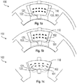
- Figs. 1a to 1c show an electrical machine 100 with a rotor 120 and show how the softpads to be manufactured may be used in an electrical machine 100.
- the figures show different states of the deformation of the elastic softpads 110 placed in a free space of the rotor 112, wherein the movement of the magnets and the deformation of the softpad 110 is illustrated.
- the permanent magnets 120 are arranged in two layers in the elastic softpad 110. Each layer contains five permanent magnets 120.
- the permanent magnets 120 are located in their original positions 101 when the softpad 110 is in a not deformed state.
- the deformation means 121, 122 exert a pressure onto the elastic softpad 110 from the bottom side, such that the permanent magnets 120 are shifted radially from positions 101 to positions 102, thereby increasing the radius R.
- the length of the elastic softpad 110 in tangential direction is increased, thereby increasing the conductor length L.
- Fig. 1c shows the deformation in a further state, where more pressure is exerted to the elastic softpad 110 than illustrated in Fig. 1b , and where the permanent magnets are pushed to position 103.
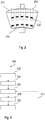
- Fig. 2 shows an illustration of how the elastic softpad 110 with permanent magnets 120 may be produced according to an embodiment.
- the elastic softpad 110 may consist of an elastic base material with holes 202 from the top side and holes 204 from the bottom side.
- the holes 200, 202 will serve as magnet mounting pockets.
- the magnets 120 therefore, may be inserted into the holes and the holes may be filled with the same or a different material as the elastic softpad base material. In the following it is described, how the elastic softpad with holes 202 and 204 may be produced.
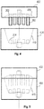
- Fig. 3 shows a flow diagram of a method 300 for manufacturing an elastic magnetic softpad, according to an embodiment.
- the method comprises the steps: providing 302 a top (half-)shell and a bottom (half-)shell forming a mold to be filled with an elastic material.
- the shells comprise a complementary structure for receiving magnets. When the top and the bottom shells are composed together the shells show the following properties:
- the complementary structure forms a cavern.
- the top shell comprises first shafts protruding to the bottom shell. These first shafts will provide first holes in the non-complementary structure.
- the bottom shell comprises second shafts protruding to the top shell, where the second shafts provide second holes in the non-complementary structure.
- the top and the bottom shell are composed 304 such that they form a form-fit cavern.
- the cavern is filled 306 with an elastic material.
- a softpad comprising the cavern filled with elastic material is extracted 308.
- a discrete magnet into is inserted 310into each of the holes, and in a final step, the holes are filled with elastic material.
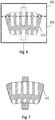
- Fig. 4 shows a diagram of a top shell 402 and a bottom shell 404, which form a mold that will be filled with an elastic base material. Since it is a mold, the structure is complementary to that after filling the mold. That is, the protruding shafts 202, 204 at the top shell 402 and the bottom shell 404 will become the holes 802 and 804 as shown in Fig. 8 , in which the permanent magnets 120 will be inserted in a later step.
- the dotted lines 410 in the top and the bottom shell 402, 404 indicate the later shape of the elastic softpad 110.
- the shape encloses a hollow volume, which is filled with the base material.
- the top shell 402 and the bottom shell 404 are composed together.
- the filling may be done, for example, by covering the filled top shell 402 with a sheet, turning the top shell and laying the top shell 402 onto the bottom shell 404, and removing the sheet, which then, i.e., before removing, is located in-between the top 402 and the bottom shell 404.
- the shape 410 encloses a cavern, which is now filled with the base material, as for example, silicone.
- the base material has now to harden so that an elastic softpad 110 is obtained.
- Fig. 7 shows a diagram of the obtained elastic softpad 110, after removing the top 402 and the bottom 404 shells.
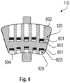
- Fig. 8 shows a diagram of the obtained elastic softpad 110, where the permanent magnets 120 have been inserted into the holes 802, 804 in such a way that the magnets 120 in respectively a top hole 802 and a bottom hole 804 attract each other, which is indicated by the solid black rectangles representing, for example the north pole 801 and the rectangles filled with a dotted structure representing, for example, the south pole 803 of a magnet 120.
- the magnets 120 may be arranged in the opposite direction.
- the permanent magnets 120 are filled up with the base material.
Landscapes
- Engineering & Computer Science (AREA)
- Power Engineering (AREA)
- Physics & Mathematics (AREA)
- Electromagnetism (AREA)
- Permanent Field Magnets Of Synchronous Machinery (AREA)
Abstract
Description
- The invention relates to a method for manufacturing an elastic magnetic softpad, an elastic softpad, the use of an elastic softpad, and an electrical machine comprising such an elastic magnetic softpad.
- Special rotor constructions for electric machines may comprise elastic softpads comprising magnetic material. Such electric machines may be operated as a motor or as a generator, in order to fulfil respective needs. The magnetic material are hosted in elastic softpads, which can be elastically deformed in a rotor in order to obtain a variable magnetic induction B, swept conductor length L, and B center of gravity radius R. These parameters contribute into above described formula for the torque M at the rotor shaft. Such a special rotor construction allows to keep the stator current in a safe region regarding Joule heat, thereby avoiding an overheating and damage/destruction of the electric machine. Furthermore, even the torque can be increased due to a respective increase of parameters B, L, and R. Such elastic softpads may be manufactured by integrating, for example, ferrite powder in an elastic softpad. Producing such softpads may be very laborious since the magnetic material has to be mixed with the elastic material, and the magnetization has to be performed in a separate step.
- Thus, a method is desired to manufacture elastic softpads in an efficient and economic way.
- The problem is solved by the subject-matter of the independent claims. Embodiments are provided by the dependent claims, the following description and the accompanying figures.
- The described embodiments similarly pertain to the method for manufacturing an elastic magnetic softpad, an elastic softpad, and the use of an elastic softpad. Synergetic effects may arise from different combinations of the embodiments although they might not be described in detail.
- Further on, it shall be noted that all embodiments of the present invention concerning a method, might be carried out with the order of the steps as described, nevertheless this has not to be the only and essential order of the steps of the method. The herein presented methods can be carried out with another order of the disclosed steps without departing from the respective method embodiment, unless explicitly mentioned to the contrary hereinafter.
- Technical terms are used by their common sense. If a specific meaning is conveyed to certain terms, definitions of terms will be given in the following in the context of which the terms are used.
- According to an aspect, a method for manufacturing an elastic magnetic softpad is provided, comprising the following steps. Note, that the order of the steps may be changed.
In a first step, a top shell and a bottom shell forming a mold to be filled with an elastic material is provided, comprising a complementary structure for receiving magnets. That is, the mold comprises two half-shells, which may be manufactured and prepared separately. The half-shells my, e.g., be manufactured using an injection molding or 3-D printing technique. - The shells have the following properties, when the top and the bottom shells are composed or put together, i.e., placed on top of each other together: The complementary structure forms a cavern, the top shell comprises first shafts protruding to the bottom shell, the first shafts providing first holes in the non-complementary structure, the bottom shell comprises second shafts protruding to the top shell, the second shafts providing second holes in the non-complementary structure, and the distal surfaces of the first shafts and the second shafts essentially face each other.
- "Complementary" means, that an inverse structure or form will be obtained when filling the half-shells or the mold with a filling material.
- The term "discrete magnets" in this disclosure is based upon discrete elements in electronics in order to distinct between loose material as ferrite powder and elements having a tangible and definite form.
- The holes, especially the first holes and/or the second holes, might be provided as blind holes in the non-complementary structure. That means, the holes have only one opening for receiving the discrete magnets.
- In a further step, the top and the bottom shell are composed or put together such that they form a form-fit cavern. The cavern has a structure inside as described above. By the form-fitting, the filling material is kept inside the cavern.
- In a next step the cavern is filled with an elastic material. This elastic material is also designated as "filling material" in this disclosure. Note, that the half-shells might be filled before the composition of the filling material or after the composition. Measures may be taken to keep inside the half-shells or to inject the filling material into the closed cavern.
- In a further step, a softpad is extracted comprising the elastic material of the filled cavern. The softpad comprises the structure as described above.
- In a next step, a discrete magnet into each of the holes and the holes with the magnets inside are filled with the elastic material. Note, that the order of inserting the magnets and filling the holes may vary. For example, this sub-step may be performed one by one, or, for example, first magnets may be inserted in all holes on the top side, then the holes are filled, and thereafter, the same procedure is applied to the bottom holes. Furthermore, in a single hole, more than one magnet may be inserted, preferably with a layer of filling material in-between two magnets.
- That is, instead of using ferrite powder, "discrete" magnets are used, which reside in, for example, a matrix-like way in the elastic softpad. The position of the magnets changes if a pressure is exerted on the softpad. For example, when exerting a pressure on a bottom side of the softpad, experiencing a counter pressure at the top side, the distance of the magnets is reduced in top-bottom direction, and increased in the direction to the left and right, and therefore changing parameters B, L, width, and R in an electrical machine application, where the elastic softpads are arranged into the rotor space, e.g., in-between an axial multi-profile cam and the envelopment of the rotor. The axial cam may have a in parts a conical shape and serve to deform the softpad. The electrical machine may be operated as a generator or a motor.
- According to an embodiment, the elastic material is silicone. Silicone has ideal properties as it is easy to handle, is elastic, durable, and has a highly availability at low costs. Polymers with similar properties may be used. Furthermore, the elastic softpads may comprise graphite for conducting the magnetic field inside the pad.
- According to an embodiment, the silicone material is of a silicone type polymerizing in no-air conditions. This means, the type of silicone may to chosen such that the silicone is well hardening in the cavern formed by the two half-shells.
- According to an embodiment, the shafts comprise different lengths. The lengths of the shafts may be chosen according the application and depend, for example, on the dimensions of the electrical machine. Further, the length may be chosen according to the desired magneto-electrical effect.
- According to an embodiment, the magnets are permanent neodium magnets. Neodium magnets are characterized by their strength magnets. Further, they are easily available at suitable dimensions, and are available at relatively low costs.
- According to an embodiment, the magnets and the shafts, and therefore also the holes, have a cylindrical shape. Not necessarily but ideally, the diameters of the magnets and the shafts or holes are the same, such that the magnets fit exactly into the holes.
- According to an embodiment the magnets are arranged such that the magnets of the top shell face the magnets of the bottom shell antipodal. That is, besides of the side effect while manufacturing the magnets on the top part and the bottom part of the softpad hold each other together, i.e., the magnets of the same column are magnetically coupled, and the desired variable magnetic field for the application is obtained.
- According to an embodiment, before filling the shells with the elastic material, the shells are covered with talcum. The talcum may be used for separating the half-shells from the silicone.
- According to an embodiment, after inserting the magnets, the free space any free space is filled with the elastic material. That is, if there are still unfilled areas, these areas are also filled with the filling material.
- According to an embodiment, the outer shape of the elastic softpads fits in a space of the rotor of an electrical machine. As described above, an electrical machine may be the main application of the elastic softpads, and the shape or dimensions are adapted to the space available in the electrical machine.
- According to an embodiment, the steps filling (the cavern with an elastic material, extracting a softpad comprising the cavern filled with elastic material, inserting a discrete magnet into each of the holes, and filling the holes with elastic material are performed repeatedly so that each of the first holes and/or each of the second holes comprise more than one layer of magnets; wherein a magnet of a layer in a hole is separated by the filling material from a neighbored magnet layer.
- According to a further aspect, an elastic softpad is provided, which is manufactured as described above.
- According to a further aspect, a use of such an elastic softpad in an electrical machine is provided.
- According to a further aspect, an electrical engine comprising an elastic softpad as described above is provided. The electrical engine comprises a rotor, the rotor having at least one free space or compartment between its shaft and its envelope, in which such an elastic softpad may be placed.
- These and other features, aspects and advantages of the present invention will become better understood with reference to the accompanying figure and the following description.
-
Fig. 1a shows an un-deformed magnetic, elastic softpad in an electrical machine, according to an embodiment, -
Fig. 1b shows a deformation of the elastic softpad in an electrical machine in a first state, according to an embodiment, -
Fig. 1c shows a deformation of the elastic softpad in an electrical machine in a further state, according to an embodiment, -
Fig. 2 shows an illustration of the underlying principle of the method, according to an embodiment, -
Fig. 3 shows a flow diagram of the method for manufacturing an elastic magnetic softpad, according to an embodiment, -
Fig. 4 shows a diagram of atop shell 402 and abottom shell 404, according to an embodiment, -
Fig. 5 shows a diagram of atop shell 402 and abottom shell 404 put together as one mold, according to an embodiment, -
Fig. 6 shows a diagram with the softpad inside the mold according to an embodiment, -
Fig. 7 shows a diagram of the elastic softpad after removing the top and the bottom shells, according to an embodiment, -
Fig. 8 shows a diagram of the obtained elastic softpad according to an embodiment. - The figures are described in the following.
-
Figs. 1a to 1c show anelectrical machine 100 with arotor 120 and show how the softpads to be manufactured may be used in anelectrical machine 100. The figures show different states of the deformation of theelastic softpads 110 placed in a free space of the rotor 112, wherein the movement of the magnets and the deformation of thesoftpad 110 is illustrated. In the example ofFig. 1a , thepermanent magnets 120 are arranged in two layers in theelastic softpad 110. Each layer contains fivepermanent magnets 120. Thepermanent magnets 120 are located in theiroriginal positions 101 when thesoftpad 110 is in a not deformed state. - In
Fig. 1b , the deformation means 121, 122 exert a pressure onto theelastic softpad 110 from the bottom side, such that thepermanent magnets 120 are shifted radially frompositions 101 topositions 102, thereby increasing the radius R. At the same time, the length of theelastic softpad 110 in tangential direction is increased, thereby increasing the conductor length L. -
Fig. 1c shows the deformation in a further state, where more pressure is exerted to theelastic softpad 110 than illustrated inFig. 1b , and where the permanent magnets are pushed toposition 103. -
Fig. 2 shows an illustration of how theelastic softpad 110 withpermanent magnets 120 may be produced according to an embodiment. Theelastic softpad 110 may consist of an elastic base material withholes 202 from the top side and holes 204 from the bottom side. Theholes 200, 202 will serve as magnet mounting pockets. Themagnets 120, therefore, may be inserted into the holes and the holes may be filled with the same or a different material as the elastic softpad base material. In the following it is described, how the elastic softpad withholes -
Fig. 3 shows a flow diagram of amethod 300 for manufacturing an elastic magnetic softpad, according to an embodiment. The method comprises the steps: providing 302 a top (half-)shell and a bottom (half-)shell forming a mold to be filled with an elastic material. The shells comprise a complementary structure for receiving magnets. When the top and the bottom shells are composed together the shells show the following properties: The complementary structure forms a cavern. The top shell comprises first shafts protruding to the bottom shell. These first shafts will provide first holes in the non-complementary structure. The bottom shell comprises second shafts protruding to the top shell, where the second shafts provide second holes in the non-complementary structure. The distal surfaces of the first shafts and the second shafts essentially face each other. In a further step of the method, the top and the bottom shell are composed 304 such that they form a form-fit cavern. In a next step the cavern is filled 306 with an elastic material. In a further next step, a softpad comprising the cavern filled with elastic material is extracted 308. In a next step a discrete magnet into is inserted 310into each of the holes, and in a final step, the holes are filled with elastic material. -
Fig. 4 shows a diagram of atop shell 402 and abottom shell 404, which form a mold that will be filled with an elastic base material. Since it is a mold, the structure is complementary to that after filling the mold. That is, the protrudingshafts top shell 402 and thebottom shell 404 will become theholes Fig. 8 , in which thepermanent magnets 120 will be inserted in a later step. Thedotted lines 410 in the top and thebottom shell elastic softpad 110. In the complementary structure of the mold, the shape encloses a hollow volume, which is filled with the base material. - As can be seen in
Fig. 5 , after filling the half-shells top shell 402 and thebottom shell 404 are composed together. The filling may be done, for example, by covering the filledtop shell 402 with a sheet, turning the top shell and laying thetop shell 402 onto thebottom shell 404, and removing the sheet, which then, i.e., before removing, is located in-between the top 402 and thebottom shell 404. - In
Fig. 6 , it can be seen that theshape 410 encloses a cavern, which is now filled with the base material, as for example, silicone. The base material has now to harden so that anelastic softpad 110 is obtained. -
Fig. 7 shows a diagram of the obtainedelastic softpad 110, after removing the top 402 and the bottom 404 shells. -
Fig. 8 shows a diagram of the obtainedelastic softpad 110, where thepermanent magnets 120 have been inserted into theholes magnets 120 in respectively atop hole 802 and abottom hole 804 attract each other, which is indicated by the solid black rectangles representing, for example thenorth pole 801 and the rectangles filled with a dotted structure representing, for example, thesouth pole 803 of amagnet 120. Themagnets 120 may be arranged in the opposite direction. - As soon as the
magnets 120 are inserted into theelastic softpads 110 the free space of the holes above or below, respectively, thepermanent magnets 120 are filled up with the base material. - Other variations to the disclosed embodiments can be understood and effected by those skilled in the art in practicing the claimed invention, from the study of the drawings, the disclosure, and the appended claims. In the claims the word "comprising" does not exclude other elements or steps and the indefinite article "a" or "an" does not exclude a plurality. The mere fact that certain measures are recited in mutually different dependent claims does not indicate that a combination of these measures cannot be used to advantage. Any reference signs in the claims should not be construed as limiting the scope of the claims.
Claims (14)
- Method (300) for manufacturing an elastic magnetic softpad (110), comprising the steps:
providing (302) a top shell (402) and a bottom shell (404) forming a mold to be filled with an elastic material, comprising a complementary structure for receiving magnets (120); wherein, when the top (402) and the bottom (404) shells are composed together:the complementary structure forms a cavern,the top shell (402) comprises first shafts (202) protruding to the bottom shell (404), the first shafts (202) providing first holes (804) in the non-complementary structure;the bottom shell comprises second shafts (204) protruding to the top shell (402), the second shafts (204) providing second holes (804) in the non-complementary structure; andthe distal surfaces of the first shafts (202) and the second shafts (204) essentially face each other;composing (304) the top (402) and the bottom (404) shell such that they form a form-fit cavern;filling (306) the cavern with an elastic material;extracting (308) a softpad (110) comprising the cavern filled with elastic material;inserting (310) a discrete magnet (120) into each of the holes (802, 804) andfilling the holes (802, 804) with elastic material. - Method (300) according to claim 1, wherein the elastic material is silicone.
- Method (300) according to claim 2, wherein the silicone material is of a silicone type polymerizing in no-air conditions.
- Method (300) according to claim 1, wherein the shafts (202, 204) comprise different lengths.
- Method (300) according to any of the preceding claims, wherein the magnets (120) are permanent neodium magnets.
- Method (300) according to any of the preceding claims, wherein the magnets (120) and the shafts (202, 204) have a cylindrical shape.
- Method (300) according to any of the preceding claims, wherein the magnets (120) are arranged such that the magnets (120) of the top shell (402) face the magnets of the bottom shell (404) antipodal.
- Method (300) according to any of the preceding claims, wherein, before filling the shells with the elastic material, the top shell (402) and the bottom shell (404) are covered with talcum.
- Method (300) according to any of the preceding claims, wherein, after inserting the magnets (120), any free space is filled with the elastic material.
- Method (300) according to any of the preceding claims, wherein an outer shape of the elastic softpad (110) fits in a space of a rotor (112) of an electrical machine (100).
- Method (300) according to any of the preceding claims, wherein the steps filling (304) the cavern with an elastic material, extracting (306) a softpad comprising the cavern filled with elastic material, inserting (308) a discrete magnet (120) into each of the holes (802, 804), and filling the holes (802, 804) with elastic material are performed repeatedly so that each of the first holes (802) and/or each of the second holes (804) comprise more than one layer of magnets (120); wherein a magnet (120) of a layer in a hole (802, 804) is separated by the elastic material from a neighbored magnet layer.
- An elastic softpad (110), which is manufactured according to any of claims 1 to 11.
- Use of an elastic softpad (110) according to claim 12 in an electrical machine (100).
- An electrical engine (100) comprising an elastic softpad (110) according to claim 12.
Priority Applications (1)
| Application Number | Priority Date | Filing Date | Title |
|---|---|---|---|
| EP20465521.1A EP3902102A1 (en) | 2020-04-21 | 2020-04-21 | Manufacturing method of a softpad comprising permanent magnets |
Applications Claiming Priority (1)
| Application Number | Priority Date | Filing Date | Title |
|---|---|---|---|
| EP20465521.1A EP3902102A1 (en) | 2020-04-21 | 2020-04-21 | Manufacturing method of a softpad comprising permanent magnets |
Publications (1)
| Publication Number | Publication Date |
|---|---|
| EP3902102A1 true EP3902102A1 (en) | 2021-10-27 |
Family
ID=70736775
Family Applications (1)
| Application Number | Title | Priority Date | Filing Date |
|---|---|---|---|
| EP20465521.1A Withdrawn EP3902102A1 (en) | 2020-04-21 | 2020-04-21 | Manufacturing method of a softpad comprising permanent magnets |
Country Status (1)
| Country | Link |
|---|---|
| EP (1) | EP3902102A1 (en) |
Citations (4)
| Publication number | Priority date | Publication date | Assignee | Title |
|---|---|---|---|---|
| DE102012210310A1 (en) * | 2012-06-19 | 2013-12-19 | Siemens Aktiengesellschaft | Preparing permanent magnet, comprises preparing first slurry comprising magnetic particles with first dimension and organic component, applying first film made of first slurry on carrier film, and passing carrier film on blade |
| US20170323715A1 (en) * | 2014-09-26 | 2017-11-09 | Elliott Chewins | Removable fluid barrier |
| CN107978415A (en) * | 2017-12-21 | 2018-05-01 | 安吉司润磁性材料有限公司 | A kind of silica gel rare earth permanent magnet component and its manufacture method |
| EP3447888A1 (en) * | 2017-08-22 | 2019-02-27 | Continental Automotive GmbH | Rotor for an electric machine of a vehicle |
-
2020
- 2020-04-21 EP EP20465521.1A patent/EP3902102A1/en not_active Withdrawn
Patent Citations (4)
| Publication number | Priority date | Publication date | Assignee | Title |
|---|---|---|---|---|
| DE102012210310A1 (en) * | 2012-06-19 | 2013-12-19 | Siemens Aktiengesellschaft | Preparing permanent magnet, comprises preparing first slurry comprising magnetic particles with first dimension and organic component, applying first film made of first slurry on carrier film, and passing carrier film on blade |
| US20170323715A1 (en) * | 2014-09-26 | 2017-11-09 | Elliott Chewins | Removable fluid barrier |
| EP3447888A1 (en) * | 2017-08-22 | 2019-02-27 | Continental Automotive GmbH | Rotor for an electric machine of a vehicle |
| CN107978415A (en) * | 2017-12-21 | 2018-05-01 | 安吉司润磁性材料有限公司 | A kind of silica gel rare earth permanent magnet component and its manufacture method |
Similar Documents
| Publication | Publication Date | Title |
|---|---|---|
| JP5762105B2 (en) | Method for manufacturing permanent magnet type rotating electric machine | |
| CN103516080B (en) | Electro-motor and its manufacture method | |
| CN106165256B (en) | Permanent magnet type rotating electric machine and manufacturing method thereof | |
| EP1164683B1 (en) | Permanent magnet rotor and method of making the same | |
| AU2010334933B2 (en) | Rotor for modulated pole machine | |
| JP5726065B2 (en) | Integrated compression molded stator | |
| US9166449B2 (en) | Rotor and motor | |
| US9899902B2 (en) | Pole to pole variation in shape of injection molded magnets of internal permanent magnet machines | |
| JP2017527247A (en) | Rotor and reluctance machine | |
| CN108028565B (en) | Rotor | |
| US20090183357A1 (en) | Magnetic powder metal composite core for electrical machines | |
| CN107852073B (en) | Rotor manufacturing method and rotor | |
| US10644576B2 (en) | Method for manufacturing an electrical machine | |
| JP6796449B2 (en) | Synchronous reluctance type rotary electric machine | |
| JP2014155415A (en) | Embedded magnet rotor and method of manufacturing embedded magnet rotor | |
| GB2511421A (en) | Electrical machines | |
| CN107438936B (en) | Permanent magnet rotor | |
| US10804758B2 (en) | Permanent magnet rotor for rotating electric machines and method for manufacturing such rotor | |
| JP2016184991A (en) | Magnet embedded type rotor and manufacturing method of the same | |
| JP2017229192A (en) | Rotating electric machine and method of manufacturing rotating electric machine | |
| US10199911B2 (en) | Orientation magnetization device and magnet-embedded rotor | |
| JP2017070031A (en) | Rotor | |
| CN106130203B (en) | Stator and motor with same | |
| EP3276793A1 (en) | Rotor assembly, in particular for an electric motor of the ipm-pmasr type, and electric motor comprising said rotor assembly | |
| JP2013121253A (en) | Rotor, and manufacturing method therefor |
Legal Events
| Date | Code | Title | Description |
|---|---|---|---|
| PUAI | Public reference made under article 153(3) epc to a published international application that has entered the european phase |
Free format text: ORIGINAL CODE: 0009012 |
|
| STAA | Information on the status of an ep patent application or granted ep patent |
Free format text: STATUS: THE APPLICATION HAS BEEN PUBLISHED |
|
| AK | Designated contracting states |
Kind code of ref document: A1 Designated state(s): AL AT BE BG CH CY CZ DE DK EE ES FI FR GB GR HR HU IE IS IT LI LT LU LV MC MK MT NL NO PL PT RO RS SE SI SK SM TR |
|
| B565 | Issuance of search results under rule 164(2) epc |
Effective date: 20201005 |
|
| RAP3 | Party data changed (applicant data changed or rights of an application transferred) |
Owner name: VITESCO TECHNOLOGIES GMBH |
|
| STAA | Information on the status of an ep patent application or granted ep patent |
Free format text: STATUS: REQUEST FOR EXAMINATION WAS MADE |
|
| 17P | Request for examination filed |
Effective date: 20220428 |
|
| RBV | Designated contracting states (corrected) |
Designated state(s): AL AT BE BG CH CY CZ DE DK EE ES FI FR GB GR HR HU IE IS IT LI LT LU LV MC MK MT NL NO PL PT RO RS SE SI SK SM TR |
|
| P01 | Opt-out of the competence of the unified patent court (upc) registered |
Effective date: 20230530 |
|
| STAA | Information on the status of an ep patent application or granted ep patent |
Free format text: STATUS: EXAMINATION IS IN PROGRESS |
|
| 17Q | First examination report despatched |
Effective date: 20230807 |
|
| STAA | Information on the status of an ep patent application or granted ep patent |
Free format text: STATUS: THE APPLICATION IS DEEMED TO BE WITHDRAWN |
|
| 18D | Application deemed to be withdrawn |
Effective date: 20241101 |