EP3902089A1 - Wireless charger - Google Patents
Wireless charger Download PDFInfo
- Publication number
- EP3902089A1 EP3902089A1 EP20200986.6A EP20200986A EP3902089A1 EP 3902089 A1 EP3902089 A1 EP 3902089A1 EP 20200986 A EP20200986 A EP 20200986A EP 3902089 A1 EP3902089 A1 EP 3902089A1
- Authority
- EP
- European Patent Office
- Prior art keywords
- wireless charger
- charging
- casing
- charged
- disposed
- Prior art date
- Legal status (The legal status is an assumption and is not a legal conclusion. Google has not performed a legal analysis and makes no representation as to the accuracy of the status listed.)
- Pending
Links
Images


Classifications
-
- H—ELECTRICITY
- H02—GENERATION; CONVERSION OR DISTRIBUTION OF ELECTRIC POWER
- H02J—CIRCUIT ARRANGEMENTS OR SYSTEMS FOR SUPPLYING OR DISTRIBUTING ELECTRIC POWER; SYSTEMS FOR STORING ELECTRIC ENERGY
- H02J7/00—Circuit arrangements for charging or depolarising batteries or for supplying loads from batteries
- H02J7/0029—Circuit arrangements for charging or depolarising batteries or for supplying loads from batteries with safety or protection devices or circuits
- H02J7/00309—Overheat or overtemperature protection
-
- H—ELECTRICITY
- H05—ELECTRIC TECHNIQUES NOT OTHERWISE PROVIDED FOR
- H05K—PRINTED CIRCUITS; CASINGS OR CONSTRUCTIONAL DETAILS OF ELECTRIC APPARATUS; MANUFACTURE OF ASSEMBLAGES OF ELECTRICAL COMPONENTS
- H05K7/00—Constructional details common to different types of electric apparatus
- H05K7/20—Modifications to facilitate cooling, ventilating, or heating
- H05K7/20009—Modifications to facilitate cooling, ventilating, or heating using a gaseous coolant in electronic enclosures
- H05K7/20136—Forced ventilation, e.g. by fans
- H05K7/20145—Means for directing air flow, e.g. ducts, deflectors, plenum or guides
-
- H—ELECTRICITY
- H02—GENERATION; CONVERSION OR DISTRIBUTION OF ELECTRIC POWER
- H02J—CIRCUIT ARRANGEMENTS OR SYSTEMS FOR SUPPLYING OR DISTRIBUTING ELECTRIC POWER; SYSTEMS FOR STORING ELECTRIC ENERGY
- H02J7/00—Circuit arrangements for charging or depolarising batteries or for supplying loads from batteries
- H02J7/0042—Circuit arrangements for charging or depolarising batteries or for supplying loads from batteries characterised by the mechanical construction
- H02J7/0044—Circuit arrangements for charging or depolarising batteries or for supplying loads from batteries characterised by the mechanical construction specially adapted for holding portable devices containing batteries
-
- H—ELECTRICITY
- H02—GENERATION; CONVERSION OR DISTRIBUTION OF ELECTRIC POWER
- H02J—CIRCUIT ARRANGEMENTS OR SYSTEMS FOR SUPPLYING OR DISTRIBUTING ELECTRIC POWER; SYSTEMS FOR STORING ELECTRIC ENERGY
- H02J50/00—Circuit arrangements or systems for wireless supply or distribution of electric power
- H02J50/005—Mechanical details of housing or structure aiming to accommodate the power transfer means, e.g. mechanical integration of coils, antennas or transducers into emitting or receiving devices
-
- H—ELECTRICITY
- H02—GENERATION; CONVERSION OR DISTRIBUTION OF ELECTRIC POWER
- H02J—CIRCUIT ARRANGEMENTS OR SYSTEMS FOR SUPPLYING OR DISTRIBUTING ELECTRIC POWER; SYSTEMS FOR STORING ELECTRIC ENERGY
- H02J50/00—Circuit arrangements or systems for wireless supply or distribution of electric power
- H02J50/10—Circuit arrangements or systems for wireless supply or distribution of electric power using inductive coupling
-
- H—ELECTRICITY
- H02—GENERATION; CONVERSION OR DISTRIBUTION OF ELECTRIC POWER
- H02J—CIRCUIT ARRANGEMENTS OR SYSTEMS FOR SUPPLYING OR DISTRIBUTING ELECTRIC POWER; SYSTEMS FOR STORING ELECTRIC ENERGY
- H02J7/00—Circuit arrangements for charging or depolarising batteries or for supplying loads from batteries
- H02J7/0042—Circuit arrangements for charging or depolarising batteries or for supplying loads from batteries characterised by the mechanical construction
-
- H—ELECTRICITY
- H05—ELECTRIC TECHNIQUES NOT OTHERWISE PROVIDED FOR
- H05K—PRINTED CIRCUITS; CASINGS OR CONSTRUCTIONAL DETAILS OF ELECTRIC APPARATUS; MANUFACTURE OF ASSEMBLAGES OF ELECTRICAL COMPONENTS
- H05K7/00—Constructional details common to different types of electric apparatus
- H05K7/20—Modifications to facilitate cooling, ventilating, or heating
- H05K7/20009—Modifications to facilitate cooling, ventilating, or heating using a gaseous coolant in electronic enclosures
- H05K7/20136—Forced ventilation, e.g. by fans
- H05K7/20172—Fan mounting or fan specifications
Abstract
Description
- With the development of technologies, terminal devices such as mobile phones can be charged by wireless charger, for example by placing them on the wireless charger. During the charging process, the devices being charged may continuously generate heat, which may result in a reduced battery life or even damage of the devices being charged. Therefore, a wireless charger is often provided with a centrifugal fan to dissipate heat.
- The present disclosure generally relates to the field of terminal device charging, and more specifically to a wireless charger.
- Various embodiments of the present disclosure provide a wireless charger configured to charge a device, and the wireless charger includes: a charging base disposed at a lower portion of the vertical wireless charger; a support portion disposed over the charging base and configured to support the device being charged; a charging coil disposed in the support portion and configured to charge the device; and a cross-flow fan located over the charging base, having a fan air outlet extending along a width direction of the support portion, and configured to dissipate heat away from the device being charged and/or the wireless charger through exhaust air.
- Optionally, the cross-flow fan includes: a fan housing having a cylindrical shape, and disposed to extend along the width direction of the support portion; a fan air inlet opened on an axial end face on one side or both sides of the fan housing; and the fan air outlet disposed in a radial direction of the fan housing and extending along an axial direction.
- Optionally, the support portion is disposed over the charging bas in an inclined and upwardly extending manner.
- Optionally, the support portion includes: a casing in which the charging coil and the cross-flow fan are disposed and the cross-flow fan being disposed under the charging coil; and wherein a first surface of the casing is used to support the device being charged; and a casing air outlet is disposed on the first surface and extending along the width direction of the support portion, and the fan air outlet of the cross-flow fan being adjacent to an inner side of the casing air outlet.
- Optionally, a side portion and/or a rear portion of the casing are provided with a casing air inlet.
- Optionally, the first surface includes: a support surface located at a lower portion of the first surface, and used to support a lower portion of the device being charged; a charging surface located at an upper portion of the first surface, the charging coil being located at a rear side of the charging surface; and a stepped surface extending along the width direction of the support portion, the support surface and the charging surface being connected through the stepped surface, and there exists a gap between the device being charged and the charging surface, when the device being charged is supported on the support surface; and wherein the casing air outlet is disposed on the stepped surface.
- Optionally, the stepped surface includes: a middle section, a first side section and a second side section; the middle section is located at a middle portion of the stepped surface, and extends along the width direction of the support portion; and the first side section and the second side section are coupled to both ends of the middle section respectively, extend toward an upper portion of the support portion, and connect to side surfaces of the casing.
- Optionally, the casing air outlet is disposed in the middle section.
- Optionally, the charging coil is disposed inside the casing movably.
- Optionally, the wireless charger further includes: a drive component disposed inside the casing, coupled to the charging coil, and used to drive the charging coil to move along a length direction of the support portion inside the casing.
- It is to be understood that both the foregoing general description and the following detailed description are exemplary and explanatory only and are not restrictive of the disclosure.
- The accompanying drawings, which are incorporated in and constitute a part of this disclosure, illustrate embodiments consistent with the present invention and, together with the description, serve to explain the principles of the present invention.
-
FIG. 1 is a schematic diagram of a wireless charger according to some embodiments. -
FIG. 2 is a schematic diagram of a wind direction of a centrifugal fan of the wireless charger according to some embodiments. -
FIG. 3 shows a three-dimensional schematic diagram of a wireless charger according to some embodiments of the present disclosure. -
FIG. 4 shows a side cross-section schematic diagram of the wireless charger according to some embodiments of the present disclosure. -
FIG. 5 shows a three-dimensional exploded schematic diagram of the wireless charger according to some embodiments of the present disclosure. -
FIG. 6 shows a partial schematic diagram of the wireless charger according to some embodiments of the present disclosure. -
FIG. 7 shows a schematic diagram of the wind direction of a cross-flow fan of the wireless charger according to some embodiments of the present disclosure. -
FIG. 8 is a three-dimensional schematic diagram of the cross-flow fan at a first angle. -
FIG. 9 is a three-dimensional schematic diagram of the cross-flow fan at a second angle. -
FIG. 10 is a three-dimensional schematic diagram of the cross-flow fan at a third angle. -
FIG. 11 is a partial schematic diagram of the wireless charger with a charging coil located at a first position. -
FIG. 12 is a partial schematic diagram of the wireless charger with a charging coil located at a second position. - Description will now be made in detail to exemplary embodiments, examples of which are illustrated in the accompanying drawings. The following description refers to the accompanying drawings in which the same numbers in different drawings represent the same or similar elements unless otherwise represented. The implementations set forth in the following description of exemplary embodiments do not represent all implementations consistent with the present invention. Instead, they are merely examples of apparatuses and methods consistent with aspects related to the present invention as recited in the appended claims.
- It should be noted that although the expressions such as "first," "second" etc. are used herein to describe different modules, steps and data of the implementations of the present disclosure, the expressions such as "first," "second" etc. are only used to distinguish different modules, steps and data, and do not indicate a specific order or importance. In fact, the expressions such as "first," "second" etc. can be used interchangeably.
- A centrifugal fan can be thin and easy to install in a wireless charger. However, a wind direction of the centrifugal fan may have a certain arc, which leads to a reduction in the linear propagation distance of the air volume and poor heat dissipation effect.
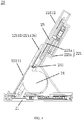
- As shown in
FIG. 1 , awireless charger 10 can have acharging coil 12 for charging a device, and acentrifugal fan 11, which has a thinner thickness and a longer size in a length direction, is used for heat dissipation. - As shown in
FIG. 2 , the wind blown out from thecentrifugal fan 11 has an arc and is skewed, which cannot achieve a good heat dissipation effect, and especially in some cases, when thecentrifugal fan 11 is far away from thecharging coil 12, the heat dissipation effect is worse, resulting in potential damages to thewireless charger 10 itself or the device being charged. - Various embodiments of the present disclosure provide a
wireless charger 20, a three-dimensional schematic diagram of which is illustrated inFIG. 3 . -
FIG. 4 shows a side cross-section schematic diagram of thewireless charger 20 according to some embodiments of the present disclosure. -
FIG. 5 shows a three-dimensional exploded schematic diagram of thewireless charger 20 according to some embodiments of the present disclosure. -
FIG. 6 shows a partial schematic diagram of thewireless charger 20 according to some embodiments of the present disclosure. -
FIG. 7 shows a schematic diagram of the wind direction of across-flow fan 24 of thewireless charger 20 according to some embodiments of the present disclosure. -
FIG. 8 to FIG. 10 show three-dimensional schematic diagrams of thecross-flow fan 24 at different angles. - The
wireless charger 20 can be used to charge a device being charged, herein, the device being charged can be a terminal device such as a mobile phone etc., and the wireless charger can be a vertical type or a tablet type. Thewireless charger 20 can include: acharging base 21, asupport portion 22, acharging coil 23 and thecross-flow fan 24. - Herein, the
charging base 21 is disposed at a lower part of thewireless charger 20, and thecharging base 21 can be provided with circuit components such as a power supply etc. of the charger, and can support thesupport portion 22. - The
support portion 22 is disposed above thecharging base 21, and is used to support the device being charged. In some embodiments, as shown inFIG. 3 to FIG. 5 , thewireless charger 20 is a vertical wireless charger, and thesupport portion 22 can be disposed above thecharging base 21 in an inclined and upwardly extending manner, and when being charged, the device being charged can lean on thesupport portion 22 and be charged. - The
charging coil 23 is disposed on thesupport portion 22, and used to charge the device being charged. The battery of the device being charged can be charged in a non-contact manner through thecharging coil 23. When the device being charged is placed or leaned on thesupport portion 22, a charging position of the device being charged corresponds to the area of thecharging coil 23, thereby forming a charging area. - The
cross-flow fan 24 is disposed above thecharging base 21, it has afan air outlet 241 extending along a width direction of thesupport portion 22, and dissipates heat away from the device being charged and/or thewireless charger 20 through exhaust air. Herein, the width direction of thesupport portion 22 can be the width direction identified inFIG. 3 , and a front side of thesupport portion 22 or acasing 221, which will be described below, refers to a side where thesupport portion 22 supports the device being charged, and a rear side refers to a side opposite to the front side, and a length direction of thesupport portion 22 is also shown accordingly inFIG. 3 . - In the above embodiment, as shown in
FIG. 7 , the wind blown out from thefan air outlet 241 propagates in a straight line and can propagate over a longer distance through thecross-flow fan 24, and thus the entire charging area can be covered, thereby the heat dissipation effect is ensured. At the same time, thefan air outlet 241 of thecross-flow fan 24 extends along the width direction of thesupport portion 22, and the extended width thereof can exceed the width of thecharging coil 23 to ensure that the wind blown out can cover the charging area. - In some embodiments, the
cross-flow fan 24 can include: afan housing 242 having a cylindrical shape, and disposed to extend along the width direction of thesupport portion 22; afan air inlet 243 opened on an axial end face on one side or both sides of thefan housing 242, or opened on a radial peripheral surface of thefan housing 242, which enable the air inlet smoother; and afan air outlet 241 disposed in a radial direction of thefan housing 242 and extending along an axial direction. Thecross-flow fan 24 can further include shafts and blades, which are not shown in the figures, disposed inside thefan housing 242. - The
cross-flow fan 24 rotates through the blades in thefan housing 242, takes in air from thefan air inlet 243 and exhausts the air through thefan air outlet 241 to generate the wind for heat dissipation. Thecross-flow fan 24 can discharge the wind propagating linearly in the radial direction from thefan air outlet 241 and blow the wind in parallel to the charging area in the width direction of thesupport portion 22 to dissipate heat. - In some embodiments, the
support portion 22 can include: acasing 221 in which thecharging coil 23 and thecross-flow fan 24 can be disposed, and thecross-flow fan 24 is disposed under thecharging coil 23; afirst surface 2211 of thecasing 221 is used to support the device being charged; and acasing air outlet 2212 is disposed on thefirst surface 2211 and extends along the width direction of thesupport portion 22, and thefan air outlet 241 of thecross-flow fan 24 is adjacent to an inner side of thecasing air outlet 2212. - In the embodiments of the present disclosure, the
casing 221 can be an integrative structure, or can be formed by combining multiple components, and in an example, as shown inFIG. 5 , thecasing 221 can include anupper casing 221a and alower casing 221b. A cavity is formed inside thecasing 221, and can accommodate thecross-flow fan 24 and the chargingcoil 23. - In the vertical wireless charger, the
cross-flow fan 24 can be located at a lower position in thecasing 221, and thefan air outlet 241 thereof can be disposed near thecasing air outlet 2212 of thefirst surface 2211, or can be directly coupled to thecasing air outlet 2212, thereby ensuring that the wind blown out from thecross-flow fan 24 can be blown out through thecasing air outlet 2212. The chargingcoil 23 is located in thecasing 221 and is located at a position above thecross-flow fan 24, which corresponds to a general charging position of the device being charged, the wind blown out from thefan air outlet 241 of thecross-flow fan 24 is blown out through thecasing air outlet 2212 and then goes through the charging area corresponding to the chargingcoil 23 to dissipate heat and cool down the device being charged and the like. - In some embodiments, a side part and/or a rear part of the
casing 221 are provided with a casing air inlet (not shown in the figures). Thecasing 221 can be provided with a casing air inlet at a corresponding position near thefan air inlet 243 of thecross-flow fan 24, the air can smoothly enter thehousing 221 and smoothly enter thecross-flow fan 24 through thefan air inlet 243, such that thecross-flow fan 24 has a better blowing effect, thereby improving the heat dissipation effect. - In some embodiments, the
first surface 2211 of thecasing 221 includes: asupport surface 22111, a chargingsurface 22112 and a steppedsurface 22113. Herein, thesupport surface 22111 is located at a lower part of thefirst surface 2211 and is used to support a lower part of the device being charged. Thesupport surface 22111 mainly serves to support the device being charged. The chargingsurface 22112 is located at an upper part of thefirst surface 2211, and the chargingcoil 23 is located at a rear side of the chargingsurface 22112, and when the device being charged is being charged, the charging area corresponds to an area located in the chargingsurface 22112. The steppedsurface 22113 extends along the width direction of thesupport portion 22, thesupport surface 22111 and the chargingsurface 22112 are connected through the steppedsurface 22113, and when thestep surface 22113 makes the device being charged supported on thesupport surface 22111, there is a gap between the device being charged and the chargingsurface 22112. - A gap formed in the charging area can improve the heat dissipation effect, allow air to circulate, and enable the wind blown out by the fan to flow through the area thereby dissipating heat. Therefore, the
first surface 2211 adopts the above result, thesupport surface 22111 at the lower part supports the device being charged, and the chargingsurface 22112 can be parallel to thesupport surface 22111 and slightly away from the device being charged as compared with thesupport surface 22111, thereby forming a gap. The height difference between thesupport surface 22111 and the chargingsurface 22112 forms the steppedsurface 22113. Thecasing air outlet 2212 is disposed on the steppedsurface 22113, such that the wind blown out by thecross-flow fan 24 can flow through the chargingsurface 22112 after being blown out through thecasing air outlet 2212, thereby dissipating heat. - In some embodiments, the stepped
surface 22113 includes: amiddle section 22113a, afirst side section 22113b and asecond side section 22113c; themiddle section 22113a is located at a middle part of the steppedsurface 22113, and extends along the width direction of thesupport portion 22; and thefirst side section 22113b and thesecond side section 22113c are coupled to both ends of themiddle section 22113a respectively, extend toward an upper part of thesupport portion 22, and connect to side surfaces of thecasing 221. - As shown in
FIG. 3 , a middle part of the steppedsurface 22113 is closer to the lower part of thesupport portion 22 than the side, since thecasing air outlet 2212 is disposed on the steppedsurface 22113, in this way, the wind blown out from thecasing air outlet 2212 can be more concentrated under the action of thefirst side section 22113b and thesecond side section 22113c on both sides, such that more wind can blow through the charging area, and the wind can be propagated with heat faster after passing the charging area of the chargingsurface 22112 without the restriction of thefirst side section 22113b and thesecond side section 22113c, thereby improving the heat dissipation efficiency. - In some embodiments, openings can be provided on the
middle section 22113a, thefirst side section 22113b and thesecond side section 22113c of the steppedsurface 22113 to form thecasing air outlet 2212. - In some other embodiments, an opening can be provided only on the
middle section 22113a to form thecasing air outlet 2212, such that the wind blown out is more concentrated, thefirst side section 22113b and thesecond side section 22113c play a role of wind gathering, and also enable thesupport surface 22111 to extend, on the side, toward the upper part of thesupport portion 22, and better support the device being charged. - In some embodiments, the charging
coil 23 is disposed inside thecasing 221 movably. In the present embodiment, the position of the chargingcoil 23 can be moved, such that it can adapt to different devices to be charged. At present, due to differences in the type and model of the devices to be charged, the charging position of each device being charged is not necessarily the same, and in order to improve charging efficiency, the position of the chargingcoil 23 can be moved to adjust, such that the chargingcoil 23 is aligned with the charging position of the device being charged. - As shown in
FIG. 11 andFIG. 12 , the chargingcoil 23 can be located at two different positions. - As shown in
FIG. 11 , the chargingcoil 23 is proximal to the lower part, and is adapted to the device being charged with a lower charging position. - As shown in
FIG. 12 , the chargingcoil 23 is proximal to the upper part, and is adapted to the device being charged with a higher charging position. In this case, it can be seen that the chargingcoil 23 is at a position farther away from thecross-flow fan 24, and in essence, this situation is that the charging position of the device being charged is higher and is farther from thecross-flow fan 24. In this case, the heat dissipation structure provided by thewireless charger 20 provided in the above embodiments of the present disclosure is even more necessary, thecross-flow fan 24 can make the blowing wind blow farther and cover the charging area. Even if the charging area is far away from thefan air outlet 241, the heat dissipation effect can be ensured. - In some embodiments, the
wireless charger 20 further includes: a drive component disposed inside thecasing 221, coupled to the chargingcoil 23, and used to drive the chargingcoil 23 to move along a length direction of thesupport portion 22 inside thecasing 221. In these embodiments, the position of the chargingcoil 23 is adjusted by the drive component. The drive component can take a variety of forms, such as cylinders and the like. - Various embodiments of the present disclosure provide a configuration mode of the drive component, as shown in
FIG. 5 , the drive component can include a steppingmotor module 251 and aguide rail 252. The steppingmotor module 251 is coupled to the chargingcoil 23 and drives the chargingcoil 23 to move; and theguide rail 252 is disposed inside thecasing 221 and cooperates with the chargingcoil 23, for example, the chargingcoil 23 can be provided correspondingly with a slider (not shown in the figures) cooperating with theguide rail 252, and the movement of the chargingcoil 23 is more stable through theguide rail 252. - The various device components, modules, units, blocks, parts, or portions may have modular configurations, or are composed of discrete components, but nonetheless can be referred to as "modules" in general. In other words, the "components," modules," "blocks," "parts," "portions," or "units" referred to herein may or may not be in modular forms, and these phrases may be interchangeably used.
- The various embodiments of the present disclosure can have one or more of the following advantages.
- By using the cross-flow fan, a size of the vertical wireless charger in a length direction can be reduced, and the wind propagates in a straight line and covers a larger size of the wireless charger in the width direction. As such, the heat dissipation effect can be improved, and the wind can propagate over a longer distance.
- It is intended that the specification and embodiments be considered as examples only. Other embodiments of the disclosure will be apparent to those skilled in the art in view of the specification and drawings of the present disclosure. That is, although specific embodiments have been described above in detail, the description is merely for purposes of illustration. It should be appreciated, therefore, that many aspects described above are not intended as required or essential elements unless explicitly stated otherwise.
- Various modifications of, and equivalent acts corresponding to, the disclosed aspects of the example embodiments, in addition to those described above, can be made by a person of ordinary skill in the art, having the benefit of the present disclosure, without departing from the scope of the disclosure defined in the following claims, the scope of which is to be accorded the broadest interpretation so as to encompass such modifications and equivalent structures.
- It should be understood that "a plurality" or "multiple" as referred to herein means two or more. "And/or," describing the association relationship of the associated objects, indicates that there may be three relationships, for example, A and/or B may indicate that there are three cases where A exists separately, A and B exist at the same time, and B exists separately. The character "/" generally indicates that the contextual objects are in an "or" relationship.
- In the present disclosure, it is to be understood that the terms "lower," "upper," "under" or "beneath" or "underneath," "above," "front," "back," "left," "right," "top," "bottom," "inner," "outer," "horizontal," "vertical," and other orientation or positional relationships are based on example orientations illustrated in the drawings, and are merely for the convenience of the description of some embodiments, rather than indicating or implying the device or component being constructed and operated in a particular orientation. Therefore, these terms are not to be construed as limiting the scope of the present disclosure.
- In the present disclosure, a first element being "on" a second element may indicate direct contact between the first and second elements, without contact, or indirect geometrical relationship through one or more intermediate media or layers, unless otherwise explicitly stated and defined. Similarly, a first element being "under," "underneath" or "beneath" a second element may indicate direct contact between the first and second elements, without contact, or indirect geometrical relationship through one or more intermediate media or layers, unless otherwise explicitly stated and defined.
- Some other embodiments of the present disclosure can be available to those skilled in the art upon consideration of the specification and practice of the various embodiments disclosed herein. The present application is intended to cover any variations, uses, or adaptations of the present disclosure following general principles of the present disclosure and include the common general knowledge or conventional technical means in the art without departing from the present disclosure. The specification and examples can be shown as illustrative only, and the true scope of the disclosure is indicated by the following claims.
Claims (14)
- A wireless charger (20), configured to charge a device, characterized in that the wireless charger comprises:a charging base (21) disposed at a lower portion of the wireless charger;a support portion (22) disposed over the charging base (21) and configured to support the device being charged;a charging coil (23) disposed in the support portion (22) and configured to charge the device; anda cross-flow fan (24), located over the charging base (21), having a fan air outlet (241) extending along a width direction of the support portion (22), and configured to dissipate heat away from the device being charged and/or the wireless charger (20) through exhaust air.
- The wireless charger (20) according to claim 1, wherein the cross-flow fan comprises:a fan housing (242) having a cylindrical shape, and disposed to extend along the width direction of the support portion (22);a fan air inlet (243) opened on an axial end face on one side or both sides of the fan housing (242); andthe fan air outlet (241) disposed in a radial direction of the fan housing (242), and extending along an axial direction.
- The wireless charger (20) according to claim 1 or 2, wherein
the support portion (22) is disposed over the charging base (21) in an inclined and upwardly extending manner. - The wireless charger (20) according to any of claims 1-3, wherein the support portion (22) comprises:a casing (221) in which the charging coil (23) and the cross-flow fan (24) are disposed and the cross-flow fan (24) being disposed under the charging coil (23), wherein a first surface (2211) of the casing (221) is configured to support the device being charged; anda casing air outlet (2212) disposed on the first surface (2211) and extending along the width direction of the support portion (22), and the fan air outlet (241) of the cross-flow fan (24) being adjacent to an inner side of the casing air outlet (2212).
- The wireless charger (20) according to claim any one of claims 1-4, wherein a side portion and/or a rear portion of the casing (221) are provided with a casing air inlet.
- The wireless charger (20) according to claim 4 or 5, wherein the first surface (2211) comprises:a support surface (22111) located at a lower portion of the first surface (2211), and configured to support a lower portion of the device being charged;a charging surface (22112) located at an upper portion of the first surface (2211), and the charging coil (23)being located at a rear side of the charging surface (22112); anda stepped surface (22113) extending along the width direction of the support portion (22), the support surface (22111) and the charging surface (22112) being connected through the stepped surface (22113, and there exists a gap between the device being charged and the charging surface (22112), when the device being charged is supported on the support surface (22112); andwherein the casing air outlet (2212) is disposed on the stepped surface (22113).
- The wireless charger (20) according to claim 6, wherein the stepped surface (22113) comprises a middle section (22113a), a first side section (22113b) and a second side section (22113c);the middle section (22113a) is located at a middle portion of the stepped surface (22113), and extends along the width direction of the support portion (22); andthe first side section (22113b) and the second side section (22113c) are coupled to both ends of the middle section (22113a) respectively, extend toward an upper portion of the support portion (22), and connect to side surfaces of the casing (221).
- The wireless charger (20) according to claim 7, wherein the casing air outlet (2212) is disposed in the middle section (22113a).
- The wireless charger (20) according to any of claims 1-8, wherein the charging coil (23) is disposed inside the casing (221) movably.
- The wireless charger (20) according to any of claims 1-9, wherein the wireless charger further (20) comprises:
a drive component disposed inside the casing, coupled to the charging coil (23), and configured to drive the charging coil (23) to move along a length direction of the support portion (22) inside the casing (221). - The wireless charger (20) according to any of claims 1 to 10, wherein the wireless charger (20) is a vertical wireless charger.
- The wireless charger (20) according to claim 11, wherein a size of the vertical wireless charger in a length direction is reduced based on the cross-flow fan (24), such that wind propagates in a straight line and covers an increased area of the wireless charger (20) in a width direction, thereby increasing heat dissipation and increasing a wind propagation distance.
- An electronic apparatus set, characterized in that it comprises the wireless charger (20) according to any of claims 1-12, and the device to be charged.
- The electronic apparatus set according to claim 13, wherein the device to be charged is a mobile phone.
Applications Claiming Priority (1)
| Application Number | Priority Date | Filing Date | Title |
|---|---|---|---|
| CN202010333066.8A CN113555914A (en) | 2020-04-24 | 2020-04-24 | Wireless charger |
Publications (1)
| Publication Number | Publication Date |
|---|---|
| EP3902089A1 true EP3902089A1 (en) | 2021-10-27 |
Family
ID=72826703
Family Applications (1)
| Application Number | Title | Priority Date | Filing Date |
|---|---|---|---|
| EP20200986.6A Pending EP3902089A1 (en) | 2020-04-24 | 2020-10-09 | Wireless charger |
Country Status (3)
| Country | Link |
|---|---|
| US (1) | US11419240B2 (en) |
| EP (1) | EP3902089A1 (en) |
| CN (1) | CN113555914A (en) |
Citations (2)
| Publication number | Priority date | Publication date | Assignee | Title |
|---|---|---|---|---|
| EP3471237A1 (en) * | 2017-10-16 | 2019-04-17 | Shenzhen Flash Cat Electronic Technology Co., Ltd. | Wireless charger |
| CN110994806A (en) * | 2019-12-02 | 2020-04-10 | Oppo广东移动通信有限公司 | Wireless charging device with heat dissipation function and wireless charging system |
Family Cites Families (3)
| Publication number | Priority date | Publication date | Assignee | Title |
|---|---|---|---|---|
| CN104578233B (en) * | 2014-08-13 | 2018-02-23 | 深圳市金溢科技股份有限公司 | A kind of wireless charging device of batch charging |
| CN112054570B (en) * | 2017-10-30 | 2022-05-31 | 华为终端有限公司 | Wireless charging equipment |
| CN110165788A (en) * | 2019-06-21 | 2019-08-23 | 宁波市瑞尔芭比医疗设备有限公司 | A kind of toilet article cradle |
-
2020
- 2020-04-24 CN CN202010333066.8A patent/CN113555914A/en active Pending
- 2020-09-09 US US17/016,208 patent/US11419240B2/en active Active
- 2020-10-09 EP EP20200986.6A patent/EP3902089A1/en active Pending
Patent Citations (2)
| Publication number | Priority date | Publication date | Assignee | Title |
|---|---|---|---|---|
| EP3471237A1 (en) * | 2017-10-16 | 2019-04-17 | Shenzhen Flash Cat Electronic Technology Co., Ltd. | Wireless charger |
| CN110994806A (en) * | 2019-12-02 | 2020-04-10 | Oppo广东移动通信有限公司 | Wireless charging device with heat dissipation function and wireless charging system |
Also Published As
| Publication number | Publication date |
|---|---|
| US20210337701A1 (en) | 2021-10-28 |
| US11419240B2 (en) | 2022-08-16 |
| CN113555914A (en) | 2021-10-26 |
Similar Documents
| Publication | Publication Date | Title |
|---|---|---|
| US20140078669A1 (en) | Display Apparatus and Electronic Apparatus | |
| US11815965B2 (en) | Cooler with wireless charging function for mobile electronic device | |
| CN103563503B (en) | Electronic equipment | |
| US11579655B2 (en) | Display lifting mechanisms | |
| US8625279B2 (en) | Display device and electronic device | |
| US20080084661A1 (en) | Heat sink pad for notebook computer | |
| JP3124854U (en) | Auxiliary device for portable information processing device | |
| US8743541B2 (en) | Display device and electronic device | |
| US20130286292A1 (en) | Television receiver and electronic apparatus | |
| JP7107399B2 (en) | charging device | |
| KR20210063757A (en) | Cooling fan controlling method and wireless charging device | |
| CN102752990A (en) | Electronic apparatus | |
| EP3902089A1 (en) | Wireless charger | |
| CN102752991A (en) | Heat sink and electronic apparatus including heat sink | |
| WO2019136692A1 (en) | Wireless charging bracket with built-in heat dissipation function | |
| CN215601050U (en) | Vehicle-mounted wireless charging device | |
| CN212033796U (en) | Wireless charger | |
| JP2002134975A (en) | Cooling fan | |
| US9719524B2 (en) | Centrifugal fan | |
| CN215814366U (en) | Portable power source rack with board in a poor light | |
| JP5335084B2 (en) | Blower | |
| CN213990235U (en) | Charging device and charging system | |
| CN215452527U (en) | Wireless charging seat and wireless charging system | |
| KR20200079154A (en) | A cooler and for a mobile device with wireless charging function | |
| CN213343116U (en) | Firewall equipment with stack structure |
Legal Events
| Date | Code | Title | Description |
|---|---|---|---|
| PUAI | Public reference made under article 153(3) epc to a published international application that has entered the european phase |
Free format text: ORIGINAL CODE: 0009012 |
|
| STAA | Information on the status of an ep patent application or granted ep patent |
Free format text: STATUS: THE APPLICATION HAS BEEN PUBLISHED |
|
| AK | Designated contracting states |
Kind code of ref document: A1 Designated state(s): AL AT BE BG CH CY CZ DE DK EE ES FI FR GB GR HR HU IE IS IT LI LT LU LV MC MK MT NL NO PL PT RO RS SE SI SK SM TR |
|
| B565 | Issuance of search results under rule 164(2) epc |
Effective date: 20210210 |
|
| STAA | Information on the status of an ep patent application or granted ep patent |
Free format text: STATUS: REQUEST FOR EXAMINATION WAS MADE |
|
| 17P | Request for examination filed |
Effective date: 20211104 |
|
| RBV | Designated contracting states (corrected) |
Designated state(s): AL AT BE BG CH CY CZ DE DK EE ES FI FR GB GR HR HU IE IS IT LI LT LU LV MC MK MT NL NO PL PT RO RS SE SI SK SM TR |
|
| STAA | Information on the status of an ep patent application or granted ep patent |
Free format text: STATUS: EXAMINATION IS IN PROGRESS |
|
| 17Q | First examination report despatched |
Effective date: 20220915 |