EP3902057A1 - Separator plate component, battery module, battery pack, device, and manufacturing method - Google Patents
Separator plate component, battery module, battery pack, device, and manufacturing method Download PDFInfo
- Publication number
- EP3902057A1 EP3902057A1 EP20905634.0A EP20905634A EP3902057A1 EP 3902057 A1 EP3902057 A1 EP 3902057A1 EP 20905634 A EP20905634 A EP 20905634A EP 3902057 A1 EP3902057 A1 EP 3902057A1
- Authority
- EP
- European Patent Office
- Prior art keywords
- sheet
- circuit board
- plug
- divisional
- separator assembly
- Prior art date
- Legal status (The legal status is an assumption and is not a legal conclusion. Google has not performed a legal analysis and makes no representation as to the accuracy of the status listed.)
- Granted
Links
Images



Classifications
-
- H—ELECTRICITY
- H01—ELECTRIC ELEMENTS
- H01M—PROCESSES OR MEANS, e.g. BATTERIES, FOR THE DIRECT CONVERSION OF CHEMICAL ENERGY INTO ELECTRICAL ENERGY
- H01M10/00—Secondary cells; Manufacture thereof
- H01M10/04—Construction or manufacture in general
- H01M10/0445—Multimode batteries, e.g. containing auxiliary cells or electrodes switchable in parallel or series connections
-
- H—ELECTRICITY
- H01—ELECTRIC ELEMENTS
- H01M—PROCESSES OR MEANS, e.g. BATTERIES, FOR THE DIRECT CONVERSION OF CHEMICAL ENERGY INTO ELECTRICAL ENERGY
- H01M50/00—Constructional details or processes of manufacture of the non-active parts of electrochemical cells other than fuel cells, e.g. hybrid cells
- H01M50/50—Current conducting connections for cells or batteries
- H01M50/502—Interconnectors for connecting terminals of adjacent batteries; Interconnectors for connecting cells outside a battery casing
- H01M50/507—Interconnectors for connecting terminals of adjacent batteries; Interconnectors for connecting cells outside a battery casing comprising an arrangement of two or more busbars within a container structure, e.g. busbar modules
-
- H—ELECTRICITY
- H01—ELECTRIC ELEMENTS
- H01M—PROCESSES OR MEANS, e.g. BATTERIES, FOR THE DIRECT CONVERSION OF CHEMICAL ENERGY INTO ELECTRICAL ENERGY
- H01M50/00—Constructional details or processes of manufacture of the non-active parts of electrochemical cells other than fuel cells, e.g. hybrid cells
- H01M50/50—Current conducting connections for cells or batteries
- H01M50/572—Means for preventing undesired use or discharge
- H01M50/584—Means for preventing undesired use or discharge for preventing incorrect connections inside or outside the batteries
- H01M50/588—Means for preventing undesired use or discharge for preventing incorrect connections inside or outside the batteries outside the batteries, e.g. incorrect connections of terminals or busbars
-
- H—ELECTRICITY
- H01—ELECTRIC ELEMENTS
- H01M—PROCESSES OR MEANS, e.g. BATTERIES, FOR THE DIRECT CONVERSION OF CHEMICAL ENERGY INTO ELECTRICAL ENERGY
- H01M50/00—Constructional details or processes of manufacture of the non-active parts of electrochemical cells other than fuel cells, e.g. hybrid cells
- H01M50/20—Mountings; Secondary casings or frames; Racks, modules or packs; Suspension devices; Shock absorbers; Transport or carrying devices; Holders
- H01M50/204—Racks, modules or packs for multiple batteries or multiple cells
- H01M50/207—Racks, modules or packs for multiple batteries or multiple cells characterised by their shape
- H01M50/209—Racks, modules or packs for multiple batteries or multiple cells characterised by their shape adapted for prismatic or rectangular cells
-
- H—ELECTRICITY
- H01—ELECTRIC ELEMENTS
- H01M—PROCESSES OR MEANS, e.g. BATTERIES, FOR THE DIRECT CONVERSION OF CHEMICAL ENERGY INTO ELECTRICAL ENERGY
- H01M50/00—Constructional details or processes of manufacture of the non-active parts of electrochemical cells other than fuel cells, e.g. hybrid cells
- H01M50/20—Mountings; Secondary casings or frames; Racks, modules or packs; Suspension devices; Shock absorbers; Transport or carrying devices; Holders
- H01M50/284—Mountings; Secondary casings or frames; Racks, modules or packs; Suspension devices; Shock absorbers; Transport or carrying devices; Holders with incorporated circuit boards, e.g. printed circuit boards [PCB]
-
- H—ELECTRICITY
- H01—ELECTRIC ELEMENTS
- H01M—PROCESSES OR MEANS, e.g. BATTERIES, FOR THE DIRECT CONVERSION OF CHEMICAL ENERGY INTO ELECTRICAL ENERGY
- H01M50/00—Constructional details or processes of manufacture of the non-active parts of electrochemical cells other than fuel cells, e.g. hybrid cells
- H01M50/50—Current conducting connections for cells or batteries
- H01M50/502—Interconnectors for connecting terminals of adjacent batteries; Interconnectors for connecting cells outside a battery casing
- H01M50/503—Interconnectors for connecting terminals of adjacent batteries; Interconnectors for connecting cells outside a battery casing characterised by the shape of the interconnectors
-
- H—ELECTRICITY
- H01—ELECTRIC ELEMENTS
- H01M—PROCESSES OR MEANS, e.g. BATTERIES, FOR THE DIRECT CONVERSION OF CHEMICAL ENERGY INTO ELECTRICAL ENERGY
- H01M50/00—Constructional details or processes of manufacture of the non-active parts of electrochemical cells other than fuel cells, e.g. hybrid cells
- H01M50/50—Current conducting connections for cells or batteries
- H01M50/502—Interconnectors for connecting terminals of adjacent batteries; Interconnectors for connecting cells outside a battery casing
- H01M50/519—Interconnectors for connecting terminals of adjacent batteries; Interconnectors for connecting cells outside a battery casing comprising printed circuit boards [PCB]
-
- H—ELECTRICITY
- H01—ELECTRIC ELEMENTS
- H01M—PROCESSES OR MEANS, e.g. BATTERIES, FOR THE DIRECT CONVERSION OF CHEMICAL ENERGY INTO ELECTRICAL ENERGY
- H01M50/00—Constructional details or processes of manufacture of the non-active parts of electrochemical cells other than fuel cells, e.g. hybrid cells
- H01M50/50—Current conducting connections for cells or batteries
- H01M50/572—Means for preventing undesired use or discharge
- H01M50/584—Means for preventing undesired use or discharge for preventing incorrect connections inside or outside the batteries
- H01M50/59—Means for preventing undesired use or discharge for preventing incorrect connections inside or outside the batteries characterised by the protection means
- H01M50/593—Spacers; Insulating plates
-
- H—ELECTRICITY
- H01—ELECTRIC ELEMENTS
- H01R—ELECTRICALLY-CONDUCTIVE CONNECTIONS; STRUCTURAL ASSOCIATIONS OF A PLURALITY OF MUTUALLY-INSULATED ELECTRICAL CONNECTING ELEMENTS; COUPLING DEVICES; CURRENT COLLECTORS
- H01R12/00—Structural associations of a plurality of mutually-insulated electrical connecting elements, specially adapted for printed circuits, e.g. printed circuit boards [PCB], flat or ribbon cables, or like generally planar structures, e.g. terminal strips, terminal blocks; Coupling devices specially adapted for printed circuits, flat or ribbon cables, or like generally planar structures; Terminals specially adapted for contact with, or insertion into, printed circuits, flat or ribbon cables, or like generally planar structures
- H01R12/50—Fixed connections
- H01R12/51—Fixed connections for rigid printed circuits or like structures
-
- H—ELECTRICITY
- H01—ELECTRIC ELEMENTS
- H01M—PROCESSES OR MEANS, e.g. BATTERIES, FOR THE DIRECT CONVERSION OF CHEMICAL ENERGY INTO ELECTRICAL ENERGY
- H01M2220/00—Batteries for particular applications
- H01M2220/20—Batteries in motive systems, e.g. vehicle, ship, plane
-
- Y—GENERAL TAGGING OF NEW TECHNOLOGICAL DEVELOPMENTS; GENERAL TAGGING OF CROSS-SECTIONAL TECHNOLOGIES SPANNING OVER SEVERAL SECTIONS OF THE IPC; TECHNICAL SUBJECTS COVERED BY FORMER USPC CROSS-REFERENCE ART COLLECTIONS [XRACs] AND DIGESTS
- Y02—TECHNOLOGIES OR APPLICATIONS FOR MITIGATION OR ADAPTATION AGAINST CLIMATE CHANGE
- Y02E—REDUCTION OF GREENHOUSE GAS [GHG] EMISSIONS, RELATED TO ENERGY GENERATION, TRANSMISSION OR DISTRIBUTION
- Y02E60/00—Enabling technologies; Technologies with a potential or indirect contribution to GHG emissions mitigation
- Y02E60/10—Energy storage using batteries
-
- Y—GENERAL TAGGING OF NEW TECHNOLOGICAL DEVELOPMENTS; GENERAL TAGGING OF CROSS-SECTIONAL TECHNOLOGIES SPANNING OVER SEVERAL SECTIONS OF THE IPC; TECHNICAL SUBJECTS COVERED BY FORMER USPC CROSS-REFERENCE ART COLLECTIONS [XRACs] AND DIGESTS
- Y02—TECHNOLOGIES OR APPLICATIONS FOR MITIGATION OR ADAPTATION AGAINST CLIMATE CHANGE
- Y02P—CLIMATE CHANGE MITIGATION TECHNOLOGIES IN THE PRODUCTION OR PROCESSING OF GOODS
- Y02P70/00—Climate change mitigation technologies in the production process for final industrial or consumer products
- Y02P70/50—Manufacturing or production processes characterised by the final manufactured product
Definitions
- the application relates to the technical field of energy storage, in particular to a separator assembly, a battery module, a battery pack, an apparatus and a manufacturing method.
- the application provides a separator assembly, a battery module, a battery pack, an apparatus and a manufacturing method, which are intended to improve anti-vibration property for the separator assembly.
- An embodiment of an aspect of the application provides a separator assembly comprising an insulating plate, a circuit board, busbars and connection sheets.
- the circuit board is arranged on the insulating plate.
- the busbars are arranged on the insulating plate on at least one side of the circuit board, and the connection sheets are connected between the busbars and the circuit board.
- the connection sheets comprise an upper connection sheet and a lower connection sheet.
- the insulating plate comprises a first surface and a second surface opposite to each other.
- the upper connection sheet is arranged on the first surface.
- the insulating plate and the lower connection sheet are arranged to be at least partially overlapped in the height direction of the separator assembly, and at least a portion of the lower connection sheet is arranged on the second surface.
- the busbars comprise a crossover busbar and an abutting busbar.
- the crossover busbar On the same side of the circuit board, at least a portion of the crossover busbar is located on the side of the abutting busbar facing towards the circuit board.
- the crossover busbar is connected to the board via the upper connection sheet and the abutting busbar is connected to the circuit board via the lower connection sheet.
- the lower connection sheet and the crossover busbar are at least partially overlapped in the height direction.
- the crossover busbar comprises a shoulder, a first connection portion and a second connection portion at two ends of the shoulder, and on the same side of the circuit board, the shoulder is located on the side of the abutting busbar facing towards the circuit board.
- the shoulder is connected to the circuit board via the upper connection sheet.
- the lower connection sheet and the shoulder are at least partially overlapped in the height direction.
- the lower connection sheet comprises a first divisional sheet connected to an abutting busbar.
- the first divisional sheet and the crossover busbar are at least partially overlapped in the height direction, and two ends of the first divisional sheet protrude from two sides of the crossover busbar in a width direction of the separator assembly.
- the lower connection sheet further comprises a second divisional sheet, via which the first divisional sheet is connected to the circuit board.
- the circuit board is provided with a relief notch at an edge in the width direction.
- the first divisional sheet extends from the abutting busbar to the relief notch, and the first divisional sheet is interconnected with the second divisional sheet at the relief notch.
- a surface of the insulating plate is recessed to form a groove, in which at least a portion of the lower connection sheet is engaged.
- the groove has a bottom wall and a side wall connected to the peripheral side of the bottom wall.
- the bottom wall is provided with a post.
- the lower connection sheet is provided with a locating hole penetrating there. The post is engaged in the locating hole.
- the separator assembly further comprises an insulating fixing member adapted to the groove in shape, and the fixing member fixes the lower connection sheet in the groove.
- the fixing member is provided with a first plug-in part, and the groove is provided with a second plug-in part adapted to the first plug-in part.
- the fixing member is fixed in the groove by the first plug-in part and the second plug-in part.
- the fixing member comprises a body portion.
- the first plug-in part is a plug-in sheet arranged to protrude from the body portion, and the second plug-in part is a plug-in slot formed by the recessed side wall.
- the plug-in sheet is provided with a plug-in hole penetrating there
- the plug-in slot is provided with a plug-in post therein
- the plug-in hole and the plug-in post are adapted in shape, such that the plug-in post is located in the plug-in hole when the plug-in sheet is located in the plug-in slot.
- the fixing member is provided with a plurality of first plug-in parts arranged at intervals on the peripheral side of the body portion. There are a plurality of second plug-in parts corresponding to the plurality of first plug-in parts, and the plurality of second plug-in parts are distributed at intervals on the side wall of the groove.
- the fixing member further comprises an enclosing portion and a cover portion sequentially connected in the extending direction thereof.
- the enclosing portion has a through hole penetrating in the extending direction.
- the lower connection sheet is inserted into the through hole.
- the cover portion covers a portion of the lower connection sheet in the groove.
- a battery module comprising: a plurality of battery cells arranged side by side in a length direction of the battery module; the aforesaid separator assembly, the busbars being connected to the battery cells respectively to form a power supply path.
- Still another aspect of the application provides a battery pack comprising: a case having an accommodation space; the aforesaid battery module arranged in the accommodation space.
- Yet another aspect of the application provides an apparatus employing a battery module as a power source, which comprises a power supply for supplying power to the apparatus and the aforesaid battery module configured to supply electric energy to the power supply.
- Still yet another aspect of the application provides a method of manufacturing a separator assembly for a battery module , comprising:
- the lower connection sheet comprises a first divisional sheet and a second divisional sheet.
- the step of providing the circuit board and the busbars on the insulating plate and the busbars being located on at least one side of the circuit board in the width direction of the separator assembly further comprises:
- the step of providing the circuit board and the busbars on the insulating plate and the busbars being located on at least one side of the circuit board in the width direction of the separator assembly further comprises: the busbars comprising a crossover busbar and an abutting busbar, the abutting busbar being arranged in the first mounting hole, on the same side of the circuit board, arranging at least a portion of the crossover busbar on the side of the abutting busbar facing towards the circuit board, and two ends of the crossover busbar being arranged to be corresponding to the second mounting holes;
- the step of providing the connection sheets comprises: arranging the second divisional sheet between the first divisional sheet and the circuit board, arranging the upper connection sheet between the crossover busbar and the circuit board, and welding the upper connection sheet, the first divisional sheet and the second divisional sheet, such that the upper connection sheet is connected between the circuit board and the crossover busbar, the first divisional sheet being connected between the abutting busbar and the second divisional sheet, the second divisional sheet being connected between the circuit board and the first divisional sheet.
- the separator assembly comprises an insulating plate, a circuit board, busbars, and connection sheets.
- the connection sheets comprises an upper connection sheet and a lower connection sheet.
- the upper connection sheet is arranged on the first surface.
- the insulating plate and the lower connection sheet are arranged to be at least partially overlapped in the height direction of the separator assembly, and at least a portion of the lower connection sheet is arranged on the second surface.
- Embodiments of the application first provide a vehicle comprising a vehicle body and a battery pack disposed in the vehicle body.
- the vehicle is a new energy vehicle, which may be a pure electric vehicle or a hybrid vehicle or an extended range vehicle.
- vehicle body is provided with a drive motor which is electrically connected to the battery pack and supplied with electric energy from the battery pack.
- the drive motor is connected to wheels on the vehicle body via a transmission mechanism so as to drive the vehicle to travel.
- the battery pack may be horizontally disposed at the bottom of the vehicle body.
- Fig. 1 is a schematic structural view of a battery pack provided in an embodiment of the application, which battery pack comprises a case and a battery module 1 located in an accommodation space of the case.
- the battery module 1 is housed in the case. There are one or more battery modules 1 disposed in the case.
- the type of the case is not limited.
- the case may be a frame-like case, a disk-like case, or a box-like case, etc., and in particular, the case may comprise a lower case part for accommodating the battery module and an upper case part closed with the lower case part.
- the battery modules 1 may be arranged in various ways.
- Fig. 2 is a schematic structural view of a battery module 1 provided in an embodiment of the application
- Fig. 3 is a schematic explosive structural view of Fig. 2 .
- the battery module 1 of the embodiment of the application comprises a housing 30, a plurality of battery cells 20 located in the housing 30 and a separator assembly 10 located on the top of the plurality of battery cells 20.
- the separator assembly 10 comprises an insulating plate 100, a circuit board 200 disposed on the insulating plate 100, a plurality of busbars 300, and connection sheets 400 connecting each busbar 300 and the circuit board 200.
- the busbars 300 and the circuit board 200 are arranged side by side in the width direction (X direction in Fig. 1 ) of the separator assembly 10, and the plurality of busbars 300 are connected to the plurality of battery cells 20 respectively to form a power supply path.
- the width direction of the separator assembly 10 refers to the direction in which the circuit board 200 and the busbars 300 are arranged side by side, and the busbars 300 are disposed in the width directionon at least one side of the circuit board 200.
- the busbars 300 are disposed in the width direction on at least one side of the circuit board 200.
- the busbars 300 are disposed in the width direction on one side of the circuit board 200, or the busbars 300 are disposed in the width direction at both sides of the circuit board 200.
- the circuit board 200 is provided with the busbars 300 in the width direction on at least one side.
- the length direction (Y direction in Fig. 4 ) of the separator assembly 10 refers to the extension direction of the circuit board 200, and the circuit board 200 is formed by extending in the length direction.
- the battery module 1 can be applied not only to a vehicle but also to other apparatuses.
- An embodiment of the application further provides an apparatus employing the battery module 1 as a power source, which comprises a power supply for supplying power to the apparatus and the aforesaid battery module 1 configured to supply electric energy to the power supply.
- the apparatus may be, but is not limited to, a vehicle, a ship, an aircraft, or the like.
- connection sheets 400 are arranged in the separator assembly 10. For example, all the connection sheets 400 are arranged on the side of the busbar 300 facing away from the insulating plate 100.
- the plurality of connection sheets 400 comprise a lower connection sheet 410 and an upper connection sheet 420.
- the insulating plate 100 comprises a first surface 150 and a second surface 160 opposite to each other.
- the upper connection sheet 420 is arranged on the first surface 150.
- the insulating plate 100 and the lower connection sheet 410 are arranged to be at least partially overlapped in the height direction (Z direction in Fig. 4 ) of the separator assembly 10 and at least a portion of the lower connection sheet 410 is arranged on the second surface 160.
- the separator assembly 10 comprises an insulating plate 100, a circuit board 200, busbars 300, and connection sheets 400.
- connection sheets 400 comprises an upper connection sheet 420 and a lower connection sheet 410.
- the upper connection sheet 420 is arranged on the first surface 150.
- the insulating plate 100 and the lower connection sheet 410 are arranged to be at least partially overlapped in the height direction of the separator assembly 10, and at least a portion of the lower connection sheet 410 is arranged on the second surface 160.
- the arrangement of the busbars 300 and the circuit board 200 is not limited.
- the circuit board 200 is arranged near a middle position in the width direction of the separator assembly 10, and a plurality of busbars 300 are arranged at both sides of the circuit board 200.
- the bus bars 300 comprises a crossover busbar 310 and an abutting busbar 320.
- the crossover busbar 310 is located on the side of the abutting busbar 320 facing towards the circuit board 200, that is, at least a portion of the crossover busbar 310 is located between the abutting busbar 320 and the circuit board 200.
- the crossover busbar 310 is connected to the circuit board 200 via the upper connection sheet 420, the abutting busbar 320 is connected to the circuit board 200 via the lower connection sheet 410, and the lower connection sheet 410 and the crossover busbar 310 are at least partially overlapped in the height direction.
- the lower connection sheet 410 and the crossover busbar 310 are arranged to be at least partially overlapped. At least a portion of the lower connection sheet 410 being located on the side of the insulating plate 100 facing away from the crossover busbar 310 has no influence on the connection between the crossover busbar 310 and the circuit board 200, and can also ensure insulation between the lower connection sheet 410 and the crossover busbar 310, thereby improving the safety performance of the separator assembly 10.
- the crossover busbar 310 comprises a shoulder 311 and a first connection portion 312 and a second connection portion 313 at two ends of the shoulder 311.
- the shoulder 311 is located on the side of the abutting busbar 320 facing towards the circuit board 200.
- the shoulder 311 is connected to the circuit board 200 via the upper connection sheet 420.
- the lower connection sheet 410 and the shoulder 311 are arranged to be at least partially overlapped in the height direction.
- the crossover busbar 310 is connected to two battery cells 20 via the first connection portion 312 and the second connection portion 313 respectively, the shoulder 311 is located between the abutting busbar 320 and the circuit board 200, and the upper connection sheet 420 is connected between the shoulder 311 and the circuit board 200.
- the lower connection sheet 410 is located on the side of the insulating plate 100 facing away from the shoulder 311 and is arranged to be at least partially overlapped with the shoulder 311. The arrangement of the lower connection sheet 410 will affect neither the connection of the crossover busbar 310 and the battery cell 20 nor the connection of the shoulder 311 and the circuit board 200.
- the shape of the crossover busbar 310 is not limited.
- the crossover busbar 310 is connected between the battery cells 20 arranged at intervals.
- the crossover bar 310 may be U-shaped.
- the first connection portion 312 and the second connection portion 313 are spaced apart in the length direction of the separator assembly 10. Two adjacent battery cells 20 spaced apart are provided between the first connection portion 312 and the second connection portion 313.
- the abutting busbar 320 is connected between the adjacent two battery cells 20, and is located in the space formed and enclosed by the first connection portion 312, the second connection portion 313 and the shoulder 311.
- the crossover busbar 310 is Z-shaped, the first connection portion 312 is formed by the shoulder 311 extending in the width direction away from the second connection portion 313, one battery cell 20 is provided between the first connection portion 312 and the second connection portion 313, and the first connection portion 312 and the second connection portion 313 extend towards two sides of the circuit board 200.
- the shape of the abutting busbar 320 is not limited.
- the abutting busbar 320 is formed by extending in the length direction and are connected between two adjacent battery cells 20.
- Fig. 7 is a schematic structural view of the separator assembly 10 without the busbars 300 and the circuit board 200 mounted thereon
- Fig. 8 is a rear view of Fig. 7 .
- the arrangement of the insulating plate 100 is not limited.
- the insulating plate 100 has a first mounting hole 130 and a second mounting hole 140 penetrating there.
- the abutting busbar 320 is located in the mounting hole 130 and is connected to the battery cell 20 in the first mounting hole 130.
- the first connection portion 312 and the second connection portion 313 extend to the second mounting hole 140, and the first connection portion 312 and the second connection portion 313 are both connected to the battery cell 20 in the second mounting hole 140.
- the lower connection sheet 410 may be arranged in various ways.
- the lower connection sheet 410 comprise a first divisional sheet 411.
- the first divisional sheet 411 is connected to the abutting busbar 320 and arranged across the crossover busbar 310, that is, the first divisional sheet 411 and the crossover busbar 310 are at least partially overlapped in the height direction, and the first divisional sheet 411 protrude from both sides of the crossover bus 310 in the width direction, such that the abutting busbar 320 is connected to the circuit board 200 via the first divisional sheet 411.
- the insulating plate 100 comprises the first mounting hole 130
- one end of the first divisional sheet 411 extends into the first mounting hole 130 and is interconnected with the abutting busbar 320 in the first mounting hole 130.
- the first divisional sheet 411 is interconnected with the abutting busbar 320 at the side of the abutting busbar 320 facing away from the battery cell 20, thereby ensuring mutual insulation between the first divisional sheet 411 and the battery cell 20.
- the lower connection sheet 410 further comprises a second divisional sheet 412, which is connected between the first divisional sheet 411 and the circuit board 200.
- the second divisional sheet 412 and the first divisional sheet 411 are arranged to intersect.
- the second divisional sheet 412 is interconnected with the first divisional sheet 411 at the side of the circuit board 200 facing away from the insulating plate 100, ensuring that the first divisional sheet 411 and the battery cell 20 are insulated from each other.
- connection position of the first divisional sheet 411 and the second divisional sheet 412 is not limited.
- the circuit board 200 is provided with a relief notch 210 at an edge in the width direction.
- the first divisional sheet 411 extends from the abutting busbar 320 to the relief notch 210, and the first divisional sheet 411 and the second divisional sheet 412 are interconnected at the relief notch 210.
- the crossover busbar 310 and the circuit board 200 are in close proximity, the relief notch 210 provides a clearance for connection of the lower connection sheet 410 and the circuit board 200, such that the first divisional sheet 411 and the second divisional sheet 412 may be interconnected in the relief notch 210. Thereby the space is saved such that the relative position of the various components within the entire separator assembly 10 is compact.
- the shape of the first divisional member 411 is not limited.
- the first divisional sheet 411 may extend linearly in the width direction; or the first divisional sheet 411 may be formed by extending in a bending path, as long as the first divisional sheet 411 can extend from the abutting busbar 320 to the relief notch 210 of the circuit board 200.
- the lower connection sheet 410 can be arranged on the insulating plate 100.
- a groove 110 is formed in the surface of the insulating plate 100, and at least a portion of the lower connection sheet 410 is engaged in the groove 110. It ensures the stability of the relative position between the lower connection sheet 410 and the insulating plate 100, so as to further improve the stability between the relative positions of the components of the separator assembly 10 upon shaking under force.
- the lower connection sheet 410 comprises the first divisional sheet 411 and the second divisional sheet 412, at least a portion of the first divisional sheet 411 is engaged in the groove 110.
- the groove 110 has a bottom wall 111 and a side wall 112 connected to the peripheral side of the bottom wall 111.
- the bottom wall 111 is provided with a post 113, and the lower connection sheet 410 comprises a locating hole 411a penetrating there.
- the post 113 is engaged in the locating hole 411a when the lower connection sheet 410 is located in the groove 110, so as to further improve the stability of the relative position between the lower connection sheet 410 and the groove 110.
- the locating hole 411a is arranged in the first divisional sheet 411.
- the separator assembly 10 further comprises an insulating fixing member 500, which is adapted to the groove 110 in shape.
- the fixing member 500 is located on the side of the lower connection sheet 410 facing away from the groove 110, and fixes the lower connection sheet 410 in the groove 110.
- the fixing member 500 is provided with a first plug-in part 520, and the groove 110 is provided with a second plug-in part 120 matched with the first plug-in part 520.
- the fixing member 500 is fixed in the groove 110 by the plug-in fitting of the first plug-in part 520 and the second plug-in part 120.
- the first plug-in part 520 and the second plug-in part 120 can be arranged in various ways.
- the fixing member 500 comprises a body portion 510
- the first plug-in part 520 is a plug-in sheet 521 protruding from the body portion 510
- the second plug-in part 120 is a plug-in slot 121 recessed in the side wall 112.
- the shape of the plug-in sheet 521 and the plug-in slot 121 are adapted in shape, such that the fixing member 500 is fixed in the groove 110 when the plug-in sheet 521 is inserted into the plug-in slot 121.
- the amount of the first plug-in parts 520 and the second plug-in parts 120 is not limited, and the first plug-in part 520 and second plug-in part 120 may each be one. Or in some other optional embodiments, there are a plurality of first plug-in parts 520 arranged at intervals on the peripheral side of the body portion 510. Accordingly, there are accordingly a plurality of second plug-in parts 120 arranged to be corresponding to the plurality of first plug-in parts 520 respectively, and the plurality of second plug-in parts 120 are distributed at intervals on the side walls 112 of the groove 110.
- first plug-in parts 520 are arranged on the side surface 515 of the body portion 510 to cooperate with the second plug-in part 120.
- a plurality of first plug-in parts 520 being arranged at intervals on the peripheral side of the body portion 510 means that a plurality of first plug-in parts 520 are arranged at intervals on the side surface 515 of the body portion 510.
- the body portion 510 has a bottom surface 513 mating with the bottom wall 111 of the groove 110, and a top surface 514 opposite to the bottom surface 513.
- the side surface 515 is connected between the bottom surface 513 and the top surface 514.
- the arrangement of the first plug-in part 520 and the second plug-in part 120 is not limited to this.
- the plug-in sheet 521 is provided with a plug-in hole 522 penetrating there, a plug-in post is formed in the plug-in slot 121, and the plug-in hole 522 and the plug-in post are adapted in shape, such that the plug-in post is located in the plug-in hole 522 when the plug-in sheet 521 is located in the plug-in slot 121.
- the stability of the relative position between the first plug-in part 520 and the second plug-in part 120 is further improved, and thereby the stability of the relative position between the fixing member 500 and the groove 110 is further improved.
- the fixing member 500 is further provided with a locating hole 530, such that the post 113 can pass through the locating hole 411a and the locating hole 530 sequentially when the lower connection sheet 410 is fixed in the groove 110 by the fixing member 500.
- the bottom wall 111 of the fixing member 500 is further provided with a locating post 540, and the bottom wall 111 of the groove 110 is further provided with a fixing hole 114 penetrating there, such that the locating post 540 can pass through the locating hole 411a and the fixing hole 114 sequentially when the lower connection sheet 410 is fixed in the groove 110 by the fixing member 500.
- the arrangement of the fixing member 500 is not limited to this.
- the fixing member 500 further comprises an enclosing portion 511 and a cover portion 512 sequentially connected in the extending direction thereof.
- the enclosing portion 511 has a through hole 511a penetrating in the extending direction.
- the lower connection sheet 410 is inserted into the through hole 511a.
- the cover portion 512 covers a portion of the lower connection sheet 410 in the groove 110.
- the cover portion 512 covers a portion of the first divisional sheet 411 in the groove 110.
- the extending direction and shape of the fixing member 500 are not limited.
- the fixing member 500 may be formed by extending in the width direction. Or the fixing member 500 may be formed by extending in a bending path, as long as the fixing member 500 can fix the lower connection sheet 410 in the groove 110.
- the application further provides a forming method for a separator assembly, in which the separator assembly is that described in any of the above first embodiments.
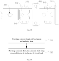
- the forming method comprises: Step S1: providing a circuit board and busbars on the insulating plate.
- busbars 300 are located on at least one side of the circuit board 200 in the width direction.
- the mounting order of the circuit board 200 and the busbars 300 is not limited herein.
- the circuit board 200 may be mounted at a middle position of the insulating plate 100 at first, and then the busbars 300 may be mounted on both sides of the circuit board 200.
- the busbars 300 may be mounted on the insulating plate 100 at first, and then the circuit board 200 may be mounted at a middle position of the insulating plate.
- Step S2 providing connection sheets, the connection sheets being connected between the busbars and the circuit board.
- connection sheets 400 comprise an upper connection sheet 420 and a lower connection sheet 410.
- the insulating plate 100 comprises a first surface 150 and a second surface 160 opposite to each other.
- the upper connection sheet 420 is arranged on the first surface 150.
- the insulating plate 100 and the lower connection sheet 410 are arranged to be at least partially overlapped in the height direction of the separator assembly 10, and at least a portion of the lower connection sheet 410 is arranged on the second surface 460.
- the sequence of the steps S1 and S2 is not limited, and the way to set the sequence of the steps S1 and S2 may be changed according to the actual process requirements.
- the step S1 further comprises: S01: forming a fixing member with a first divisional sheet.
- step S01 at least a portion of the first divisional sheet 411 is wrapped by the fixing member 500, and both ends of the first divisional sheet 411 protrude from the fixed member 500.
- the first divisional sheet 411 is directly placed into a mold and injection-molded as the fixing member 500 with the first divisional sheet 411.
- the fixing member 500 is injection-molded in the mold at first, and then the first divisional sheet 411 is mounted to the fixing member. It is only required that at least a portion of the first divisional sheet 411 is wrapped by the fixing member 500 and both ends of the first divisional sheet 411 protrude from the fixing member 500.
- the insulating plate 100 comprises a first surface 150 and a second surface 160 opposite to each other. At least a portion of the first divisional sheet 411 is located on the second surface 160.
- the insulating plate 100 has a first mounting hole 130 and a second mounting hole 140 penetrating there. One end of the first divisional sheet 411 protrudes into the first mounting hole 130.
- the busbars 300 comprise a crossover busbar 310 and an abutting busbar 320.
- the step S1 comprises: arranging the abutting busbar 300 in the first mounting hole 130, on the same side of the circuit board 200, arranging at least a portion of the crossover busbar 310 on the side of the abutting busbar 320 facing towards the circuit board 200, and both ends of the crossover busbar 310 being arranged to be corresponding to the second mounting holes 140.
- Step S2 further comprises: arranging a second divisional sheet 412 between the first divisional sheet 411 and the circuit board 200, arranging the upper connection sheet 420 between the crossover busbar 310 and the circuit board 200, and welding the upper connection sheet 420, the first divisional sheet 411 and the second divisional sheet 412, such that the upper connection sheet 420 is connected between the circuit board 200 and the crossover busbar 310, the first divisional sheet 411 being connected between the abutting busbar 320 and the second divisional sheet 412, the second divisional sheet 412 being connected between the circuit board 200 and the first divisional sheet 411.
- the welding order of the upper connection sheet 420, the first divisional sheet 411 and the second divisional sheet 412 is not limited herein.
- the upper connection sheet 420 may be welded between the crossover busbar 310 and the circuit board 200 at first, and then the second divisional sheet 412 is welded between the first divisional sheet 411 and the circuit board 200, and the first divisional sheet 411 are welded with the abutting busbar 320 at last.
- the second divisional sheet 412 is welded between first divisional sheet 41 and the circuit board 200 first, and then the upper connection sheet 420 is welded between the crossover busbar 310 and the circuit board 200, and the first divisional sheet 411 and the abutting busbar 320 are welded at last. It is also possible that the first divisional sheet 411 and the abutting busbar 320 are welded first, and then the upper connection sheet 420 and the second divisional sheet 412 are welded.
- busbars 300 and a pole 21 of the battery cell 20 are welded to each other when the separator assembly 10 is arranged in the battery module 1.
- the sequence of welding the busbars 300 and the pole post 21 and welding the busbars 300 and connection sheets 400 is not limited.
- the corresponding positions of the busbars 300 may be welded to the pole pillars 21 at first.
- the connection sheets 400 may be welded between the busbars 300 and the circuit board 200 at first.
Landscapes
- Chemical & Material Sciences (AREA)
- Chemical Kinetics & Catalysis (AREA)
- Electrochemistry (AREA)
- General Chemical & Material Sciences (AREA)
- Engineering & Computer Science (AREA)
- Manufacturing & Machinery (AREA)
- Battery Mounting, Suspending (AREA)
- Connection Of Batteries Or Terminals (AREA)
Abstract
Description
- The application claims the priority benefits of
Chinese Patent Application No. 201911377593.2 filed on December 27, 2019 - The application relates to the technical field of energy storage, in particular to a separator assembly, a battery module, a battery pack, an apparatus and a manufacturing method.
- With the transformation of energy structure, sustainable electric power has gradually replaced traditional fossil fuels as the mainstream energy. For example, electric automobiles are gradually replacing traditional fuel vehicles as a new development trend, so that the chargeable-and-dischargeable batteries have been rapidly developed.
- With the popularization of new energy pure electric automobiles, the requirements of the various main engine plants for power battery pack are becoming more and more diversified, and in particular the requirements for energy density, safety and compatibility of the modules are becoming higher and higher. With respect to the current battery module in which a plurality of internal battery cells are connected in series, the conventional arrangement for connection sheet is insufficient in terms of safety.
- Therefore, there is an urgent need for a new separator assembly, battery module, battery pack, apparatus, and manufacturing method.
- The application provides a separator assembly, a battery module, a battery pack, an apparatus and a manufacturing method, which are intended to improve anti-vibration property for the separator assembly.
- An embodiment of an aspect of the application provides a separator assembly comprising an insulating plate, a circuit board, busbars and connection sheets. The circuit board is arranged on the insulating plate. The busbars are arranged on the insulating plate on at least one side of the circuit board, and the connection sheets are connected between the busbars and the circuit board. Wherein the connection sheets comprise an upper connection sheet and a lower connection sheet. The insulating plate comprises a first surface and a second surface opposite to each other. The upper connection sheet is arranged on the first surface. The insulating plate and the lower connection sheet are arranged to be at least partially overlapped in the height direction of the separator assembly, and at least a portion of the lower connection sheet is arranged on the second surface.
- According to an aspect of the application, the busbars comprise a crossover busbar and an abutting busbar. On the same side of the circuit board, at least a portion of the crossover busbar is located on the side of the abutting busbar facing towards the circuit board. The crossover busbar is connected to the board via the upper connection sheet and the abutting busbar is connected to the circuit board via the lower connection sheet. The lower connection sheet and the crossover busbar are at least partially overlapped in the height direction.
- According to an aspect of the application, the crossover busbar comprises a shoulder, a first connection portion and a second connection portion at two ends of the shoulder, and on the same side of the circuit board, the shoulder is located on the side of the abutting busbar facing towards the circuit board. The shoulder is connected to the circuit board via the upper connection sheet. The lower connection sheet and the shoulder are at least partially overlapped in the height direction.
- According to an aspect of the application, the lower connection sheet comprises a first divisional sheet connected to an abutting busbar. The first divisional sheet and the crossover busbar are at least partially overlapped in the height direction, and two ends of the first divisional sheet protrude from two sides of the crossover busbar in a width direction of the separator assembly.
- According to an aspect of the application, the lower connection sheet further comprises a second divisional sheet, via which the first divisional sheet is connected to the circuit board.
- According to an aspect of the application, the circuit board is provided with a relief notch at an edge in the width direction. The first divisional sheet extends from the abutting busbar to the relief notch, and the first divisional sheet is interconnected with the second divisional sheet at the relief notch.
- According to an aspect of the application, a surface of the insulating plate is recessed to form a groove, in which at least a portion of the lower connection sheet is engaged.
- According to an aspect of the application, the groove has a bottom wall and a side wall connected to the peripheral side of the bottom wall. The bottom wall is provided with a post. The lower connection sheet is provided with a locating hole penetrating there. The post is engaged in the locating hole.
- According to an aspect of the application, the separator assembly further comprises an insulating fixing member adapted to the groove in shape, and the fixing member fixes the lower connection sheet in the groove.
- According to an aspect of the application, the fixing member is provided with a first plug-in part, and the groove is provided with a second plug-in part adapted to the first plug-in part. The fixing member is fixed in the groove by the first plug-in part and the second plug-in part.
- According to an aspect of the application, the fixing member comprises a body portion. The first plug-in part is a plug-in sheet arranged to protrude from the body portion, and the second plug-in part is a plug-in slot formed by the recessed side wall.
- According to an aspect of the application, the plug-in sheet is provided with a plug-in hole penetrating there, the plug-in slot is provided with a plug-in post therein, and the plug-in hole and the plug-in post are adapted in shape, such that the plug-in post is located in the plug-in hole when the plug-in sheet is located in the plug-in slot.
- According to an aspect of the application, the fixing member is provided with a plurality of first plug-in parts arranged at intervals on the peripheral side of the body portion. There are a plurality of second plug-in parts corresponding to the plurality of first plug-in parts, and the plurality of second plug-in parts are distributed at intervals on the side wall of the groove.
- According to an aspect of the application, the fixing member further comprises an enclosing portion and a cover portion sequentially connected in the extending direction thereof. The enclosing portion has a through hole penetrating in the extending direction. The lower connection sheet is inserted into the through hole. The cover portion covers a portion of the lower connection sheet in the groove.
- Another aspect of the application provides a battery module comprising: a plurality of battery cells arranged side by side in a length direction of the battery module; the aforesaid separator assembly, the busbars being connected to the battery cells respectively to form a power supply path.
- Still another aspect of the application provides a battery pack comprising: a case having an accommodation space; the aforesaid battery module arranged in the accommodation space.
- Yet another aspect of the application provides an apparatus employing a battery module as a power source, which comprises a power supply for supplying power to the apparatus and the aforesaid battery module configured to supply electric energy to the power supply.
- Still yet another aspect of the application provides a method of manufacturing a separator assembly for a battery module , comprising:
- providing a circuit board and busbars on an insulating plate and the busbars being located on at least one side of the circuit board in a width direction of the separator assembly;
- providing connection sheets, the connection sheets being arranged between the busbars and the circuit board, wherein the connection sheets comprises an upper connection sheet and a lower connection sheet, the insulating plate comprising a first surface and a second surface opposite to each other, the upper connection sheet being arranged on the first surface, the insulating plate and the lower connection sheet being arranged to be at least partially overlapped in a height direction of the separator assembly, and at least a portion of the lower connection sheet being arranged on the second surface.
- According to an aspect of the application, the lower connection sheet comprises a first divisional sheet and a second divisional sheet.
- The step of providing the circuit board and the busbars on the insulating plate and the busbars being located on at least one side of the circuit board in the width direction of the separator assembly further comprises:
- forming a fixing member with the first divisional sheet, at least a portion of the first divisional sheet being wrapped by the fixing member, and two ends of the first divisional sheet protruding from the fixing member;
- placing the fixing member with the first divisional sheet in a mold, injection molding the insulating plate, and at least a portion of the first divisional sheet being located on the second surface, the insulating plate having a first mounting hole and a second mounting hole penetrating there, one end of the first divisional sheet protruding into the first mounting hole.
- The step of providing the circuit board and the busbars on the insulating plate and the busbars being located on at least one side of the circuit board in the width direction of the separator assembly further comprises:
the busbars comprising a crossover busbar and an abutting busbar, the abutting busbar being arranged in the first mounting hole, on the same side of the circuit board, arranging at least a portion of the crossover busbar on the side of the abutting busbar facing towards the circuit board, and two ends of the crossover busbar being arranged to be corresponding to the second mounting holes; - The step of providing the connection sheets comprises:
arranging the second divisional sheet between the first divisional sheet and the circuit board, arranging the upper connection sheet between the crossover busbar and the circuit board, and welding the upper connection sheet, the first divisional sheet and the second divisional sheet, such that the upper connection sheet is connected between the circuit board and the crossover busbar, the first divisional sheet being connected between the abutting busbar and the second divisional sheet, the second divisional sheet being connected between the circuit board and the first divisional sheet. - In the separator assembly of the embodiment of the application, the separator assembly comprises an insulating plate, a circuit board, busbars, and connection sheets. The connection sheets comprises an upper connection sheet and a lower connection sheet. The upper connection sheet is arranged on the first surface. The insulating plate and the lower connection sheet are arranged to be at least partially overlapped in the height direction of the separator assembly, and at least a portion of the lower connection sheet is arranged on the second surface. In the case of vibration of the separator assembly by force, since the upper connection sheet and at least a portion of the lower connection sheet are arranged at two sides of the insulating plate, a portion of the forces exerted by the lower connection sheet and the upper connection sheet on the insulating plate may cancel each other out, so as to reduce the force applied to the insulating plate. Thereby the vibration amplitude of the separator assembly is reduced and the anti-vibration property of the separator assembly is improved to ensure the stability of the relative positions of the various components in the separator assembly, such that the reliability of the connection between the components is enhanced.
- Other features, objects and advantages of the application will become more apparent upon reading the following detailed description of non-limiting embodiments with reference to the accompanying drawings, in which the same or similar reference numerals refer to identical or similar features.
-
Fig. 1 is a schematic structural view of a battery pack according to an embodiment of the application; -
Fig. 2 is a schematic structural view of a battery module according to an embodiment of the application; -
Fig. 3 is a schematic explosive structural view ofFig. 2 ; -
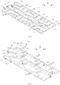
Fig. 4 is a schematic structural view of a separator assembly according to an embodiment of the application; -
Fig. 5 is a schematic explosive structural view ofFig. 4 ; -
Fig. 6 is a partially enlarged schematic structural view ofFig. 5 ; -
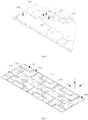
Fig. 7 is a schematic structural view of a process of assembling a separator assembly according to an embodiment of the application; -
Fig. 8 is a rear view ofFig 7 ; -
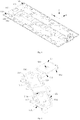
Fig. 9 is a schematic structural view of a fixing member of a separator assembly according to an embodiment of the application; -
Fig. 10 is a schematic view of a plane structure of a fixing member of a separator assembly according to an embodiment of the application; -
Fig. 11 is a schematic structural view of a fixing member of a separator assembly according to another embodiment of the application; -
Fig. 12 is a schematic view of a plane structure of a fixing member of a separator assembly according to another embodiment of the application; -
Fig. 13 is a flow chart of a method of manufacturing a separator assembly of a battery module according to still another embodiment of the application. -
- 1 battery module; 10 separator assembly;
- 100 insulating plate; 110 groove; 111 bottom wall; 112 side wall; 113 pillar; 114 fixing hole; 120 second plug-in part; 121 plug-in slot; 130 first mounting hole; 140 secondary mounting hole; 150 first surface; 160 second surface;
- 200 circuit board; 210 relief notch;
- 300 busbar; 310 crossover busbar; 311 shoulder; 312 first connection portion; 313 second connection portion; 320 abutting busbar;
- 400 connection sheet; 410 lower connection sheet; 411 first divisional sheet; 411a locating hole; 412 second divisional sheet; 420 upper connection sheet;
- 500 fixing member, 510 body portion; 511 enclosing portion; 511a through hole; 512 cover portion; 513 bottom surface; 514 top surface; 515 side surface; 520 first plug-in part; 521 plug-in sheet; 522 plug-in hole; 530 locating hole; 540 locating post;
- 20 battery cell; 21 pole;
- 30 housing;
- 2 upper cover;
- 3 case;
- X width direction; Y length direction; Z height direction.
- The features in various aspects and exemplary embodiments of the application will be described in details below. In the following detailed description, numerous specific details are set forth in order to provide a thorough understanding of the present application. However, it is apparent to a person skilled in the art that the application may be implemented without some of these specific details. The following description of the embodiments is for the purpose of better understanding of the application through showing examples of the application. In the drawings and the following description, at least a portion of well-known structures and techniques are not shown in order to avoid unnecessarily obscuring the present application, and, for clarity, the dimensions of a portion of the structures may be exaggerated. In addition, the features, structures and characters described hereafter may be combined in any suitable way in one or more embodiments.
- In the description of the application, it is noted that, except as otherwise noted, the term "a plurality of' means two or more; the orientation or position relationship indicated by the terms "above", "below", "left", "right", "in", "out" is only for the purpose of brief description of the application, rather than indicating or implying that the noted unit or element is necessarily of the specific orientation or structured or operated in the specific orientation, thus, cannot be regarded as limit of the invention. In addition, the terms such as "first", "second" and the like are only for the purpose of description, and shall not be deemed to indicate or imply relative importance.
- All the orientation terms present in the following description are the directions in the drawings, and do not limit a specific structure of the product according to the application. In the description of the application, it is also noted that, except as otherwise stipulated or limited explicitly, the terms "mount", "connect" shall be interpreted expansively, for example, it may be fixed connection, removable connection or integral connection; may be direct connection or indirect connection. For a person of ordinary skill in the art, the specific meaning of the above terms in the application can be interpreted depending on the specific situation.
- For better understanding of the application, the separator assembly, the battery module, the battery pack, the apparatus and the manufacturing method thereof will be described below in detail in combination with
Figs. 1 to 13 . - Embodiments of the application first provide a vehicle comprising a vehicle body and a battery pack disposed in the vehicle body.
- Wherein, the vehicle is a new energy vehicle, which may be a pure electric vehicle or a hybrid vehicle or an extended range vehicle. The vehicle body is provided with a drive motor which is electrically connected to the battery pack and supplied with electric energy from the battery pack. The drive motor is connected to wheels on the vehicle body via a transmission mechanism so as to drive the vehicle to travel. Optionally, the battery pack may be horizontally disposed at the bottom of the vehicle body.
- As shown in
Fig. 1 which is a schematic structural view of a battery pack provided in an embodiment of the application, which battery pack comprises a case and abattery module 1 located in an accommodation space of the case. - The
battery module 1 is housed in the case. There are one ormore battery modules 1 disposed in the case. The type of the case is not limited. The case may be a frame-like case, a disk-like case, or a box-like case, etc., and in particular, the case may comprise a lower case part for accommodating the battery module and an upper case part closed with the lower case part. - The
battery modules 1 may be arranged in various ways.Fig. 2 is a schematic structural view of abattery module 1 provided in an embodiment of the application, andFig. 3 is a schematic explosive structural view ofFig. 2 . Thebattery module 1 of the embodiment of the application comprises ahousing 30, a plurality ofbattery cells 20 located in thehousing 30 and aseparator assembly 10 located on the top of the plurality ofbattery cells 20. Theseparator assembly 10 comprises an insulatingplate 100, acircuit board 200 disposed on the insulatingplate 100, a plurality ofbusbars 300, andconnection sheets 400 connecting eachbusbar 300 and thecircuit board 200. Thebusbars 300 and thecircuit board 200 are arranged side by side in the width direction (X direction inFig. 1 ) of theseparator assembly 10, and the plurality ofbusbars 300 are connected to the plurality ofbattery cells 20 respectively to form a power supply path. - The width direction of the
separator assembly 10 refers to the direction in which thecircuit board 200 and thebusbars 300 are arranged side by side, and thebusbars 300 are disposed in the width directionon at least one side of thecircuit board 200. There are two ways to arrange thebusbars 300 in the width direction on at least one side of thecircuit board 200. For example, thebusbars 300 are disposed in the width direction on one side of thecircuit board 200, or thebusbars 300 are disposed in the width direction at both sides of thecircuit board 200. As long as thecircuit board 200 is provided with thebusbars 300 in the width direction on at least one side. - The length direction (Y direction in
Fig. 4 ) of theseparator assembly 10 refers to the extension direction of thecircuit board 200, and thecircuit board 200 is formed by extending in the length direction. - The
battery module 1 can be applied not only to a vehicle but also to other apparatuses. An embodiment of the application further provides an apparatus employing thebattery module 1 as a power source, which comprises a power supply for supplying power to the apparatus and theaforesaid battery module 1 configured to supply electric energy to the power supply. The apparatus may be, but is not limited to, a vehicle, a ship, an aircraft, or the like. - There are various ways to arrange the
connection sheets 400 in theseparator assembly 10. For example, all theconnection sheets 400 are arranged on the side of thebusbar 300 facing away from the insulatingplate 100. - Referring to
Figs. 4 to 6 , in some other optional embodiments, the plurality ofconnection sheets 400 comprise alower connection sheet 410 and anupper connection sheet 420. The insulatingplate 100 comprises afirst surface 150 and asecond surface 160 opposite to each other. Theupper connection sheet 420 is arranged on thefirst surface 150. The insulatingplate 100 and thelower connection sheet 410 are arranged to be at least partially overlapped in the height direction (Z direction inFig. 4 ) of theseparator assembly 10 and at least a portion of thelower connection sheet 410 is arranged on thesecond surface 160. - In the
separator assembly 10 of the embodiment of the application, theseparator assembly 10 comprises an insulatingplate 100, acircuit board 200,busbars 300, andconnection sheets 400. Wherein theconnection sheets 400 comprises anupper connection sheet 420 and alower connection sheet 410. Theupper connection sheet 420 is arranged on thefirst surface 150. The insulatingplate 100 and thelower connection sheet 410 are arranged to be at least partially overlapped in the height direction of theseparator assembly 10, and at least a portion of thelower connection sheet 410 is arranged on thesecond surface 160. In the case of vibration of theseparator assembly 10 by force, since theupper connection sheet 420 and at least a portion of thelower connection sheet 410 are arranged at two sides of the insulatingplate 100, a portion of the forces exerted by thelower connection sheet 410 and theupper connection sheet 420 on the insulatingplate 100 may cancel each other out, so as to reduce the force applied to the insulatingplate 100. Thereby the vibration amplitude of theseparator assembly 10 is reduced and the anti-vibration property of theseparator assembly 10 is improved to ensure the stability of the relative positions of the various components in theseparator assembly 10, such that the reliability of the connection between the components is enhanced. - The arrangement of the
busbars 300 and thecircuit board 200 is not limited. In some optional embodiments, thecircuit board 200 is arranged near a middle position in the width direction of theseparator assembly 10, and a plurality ofbusbars 300 are arranged at both sides of thecircuit board 200. - There are various ways to arrange the bus bars 300. In some optional embodiments, the bus bars 300 comprises a
crossover busbar 310 and an abuttingbusbar 320. On the same side of thecircuit board 200, at least a portion of thecrossover busbar 310 is located on the side of the abuttingbusbar 320 facing towards thecircuit board 200, that is, at least a portion of thecrossover busbar 310 is located between the abuttingbusbar 320 and thecircuit board 200. - The
crossover busbar 310 is connected to thecircuit board 200 via theupper connection sheet 420, the abuttingbusbar 320 is connected to thecircuit board 200 via thelower connection sheet 410, and thelower connection sheet 410 and thecrossover busbar 310 are at least partially overlapped in the height direction. - Since at least a portion of the
crossover busbar 310 is located between the abuttingbusbar 320 and thecircuit board 200 and thelower connection sheet 410 spans thecrossover busbar 310 and is connected between the abuttingbusbar 320 and thecircuit board 200, thelower connection sheet 410 and thecrossover busbar 310 are arranged to be at least partially overlapped. At least a portion of thelower connection sheet 410 being located on the side of the insulatingplate 100 facing away from thecrossover busbar 310 has no influence on the connection between thecrossover busbar 310 and thecircuit board 200, and can also ensure insulation between thelower connection sheet 410 and thecrossover busbar 310, thereby improving the safety performance of theseparator assembly 10. - There are various ways to arrange the
crossover busbar 310. In some optional embodiments, thecrossover busbar 310 comprises ashoulder 311 and afirst connection portion 312 and asecond connection portion 313 at two ends of theshoulder 311. On the same side of thecircuit board 200, theshoulder 311 is located on the side of the abuttingbusbar 320 facing towards thecircuit board 200. Theshoulder 311 is connected to thecircuit board 200 via theupper connection sheet 420. Thelower connection sheet 410 and theshoulder 311 are arranged to be at least partially overlapped in the height direction. - In these optional embodiments, the
crossover busbar 310 is connected to twobattery cells 20 via thefirst connection portion 312 and thesecond connection portion 313 respectively, theshoulder 311 is located between the abuttingbusbar 320 and thecircuit board 200, and theupper connection sheet 420 is connected between theshoulder 311 and thecircuit board 200. Thelower connection sheet 410 is located on the side of the insulatingplate 100 facing away from theshoulder 311 and is arranged to be at least partially overlapped with theshoulder 311. The arrangement of thelower connection sheet 410 will affect neither the connection of thecrossover busbar 310 and thebattery cell 20 nor the connection of theshoulder 311 and thecircuit board 200. - The shape of the
crossover busbar 310 is not limited. Thecrossover busbar 310 is connected between thebattery cells 20 arranged at intervals. For example, thecrossover bar 310 may be U-shaped. Thefirst connection portion 312 and thesecond connection portion 313 are spaced apart in the length direction of theseparator assembly 10. Twoadjacent battery cells 20 spaced apart are provided between thefirst connection portion 312 and thesecond connection portion 313. The abuttingbusbar 320 is connected between the adjacent twobattery cells 20, and is located in the space formed and enclosed by thefirst connection portion 312, thesecond connection portion 313 and theshoulder 311. - Alternatively, the
crossover busbar 310 is Z-shaped, thefirst connection portion 312 is formed by theshoulder 311 extending in the width direction away from thesecond connection portion 313, onebattery cell 20 is provided between thefirst connection portion 312 and thesecond connection portion 313, and thefirst connection portion 312 and thesecond connection portion 313 extend towards two sides of thecircuit board 200. - The shape of the abutting
busbar 320 is not limited. The abuttingbusbar 320 is formed by extending in the length direction and are connected between twoadjacent battery cells 20. - Please also refer to
Figs. 5 to 8 , in whichFig. 7 is a schematic structural view of theseparator assembly 10 without thebusbars 300 and thecircuit board 200 mounted thereon, andFig. 8 is a rear view ofFig. 7 . The arrangement of the insulatingplate 100 is not limited. In some optional embodiments, the insulatingplate 100 has a first mountinghole 130 and asecond mounting hole 140 penetrating there. The abuttingbusbar 320 is located in the mountinghole 130 and is connected to thebattery cell 20 in the first mountinghole 130. Thefirst connection portion 312 and thesecond connection portion 313 extend to thesecond mounting hole 140, and thefirst connection portion 312 and thesecond connection portion 313 are both connected to thebattery cell 20 in thesecond mounting hole 140. - The
lower connection sheet 410 may be arranged in various ways. In some optional embodiments, thelower connection sheet 410 comprise a firstdivisional sheet 411. The firstdivisional sheet 411 is connected to the abuttingbusbar 320 and arranged across thecrossover busbar 310, that is, the firstdivisional sheet 411 and thecrossover busbar 310 are at least partially overlapped in the height direction, and the firstdivisional sheet 411 protrude from both sides of thecrossover bus 310 in the width direction, such that the abuttingbusbar 320 is connected to thecircuit board 200 via the firstdivisional sheet 411. - Wherein when the insulating
plate 100 comprises the first mountinghole 130, one end of the firstdivisional sheet 411 extends into the first mountinghole 130 and is interconnected with the abuttingbusbar 320 in the first mountinghole 130. Optionally, the firstdivisional sheet 411 is interconnected with the abuttingbusbar 320 at the side of the abuttingbusbar 320 facing away from thebattery cell 20, thereby ensuring mutual insulation between the firstdivisional sheet 411 and thebattery cell 20. - Further, the
lower connection sheet 410 further comprises a seconddivisional sheet 412, which is connected between the firstdivisional sheet 411 and thecircuit board 200. Optionally, the seconddivisional sheet 412 and the firstdivisional sheet 411 are arranged to intersect. In some other optional embodiments, the seconddivisional sheet 412 is interconnected with the firstdivisional sheet 411 at the side of thecircuit board 200 facing away from the insulatingplate 100, ensuring that the firstdivisional sheet 411 and thebattery cell 20 are insulated from each other. - The connection position of the first
divisional sheet 411 and the seconddivisional sheet 412 is not limited. In some optional embodiments, thecircuit board 200 is provided with arelief notch 210 at an edge in the width direction. The firstdivisional sheet 411 extends from the abuttingbusbar 320 to therelief notch 210, and the firstdivisional sheet 411 and the seconddivisional sheet 412 are interconnected at therelief notch 210. When thecrossover busbar 310 and thecircuit board 200 are in close proximity, therelief notch 210 provides a clearance for connection of thelower connection sheet 410 and thecircuit board 200, such that the firstdivisional sheet 411 and the seconddivisional sheet 412 may be interconnected in therelief notch 210. Thereby the space is saved such that the relative position of the various components within theentire separator assembly 10 is compact. - The shape of the first
divisional member 411 is not limited. The firstdivisional sheet 411 may extend linearly in the width direction; or the firstdivisional sheet 411 may be formed by extending in a bending path, as long as the firstdivisional sheet 411 can extend from the abuttingbusbar 320 to therelief notch 210 of thecircuit board 200. - The
lower connection sheet 410 can be arranged on the insulatingplate 100. In some optional embodiments, agroove 110 is formed in the surface of the insulatingplate 100, and at least a portion of thelower connection sheet 410 is engaged in thegroove 110. It ensures the stability of the relative position between thelower connection sheet 410 and the insulatingplate 100, so as to further improve the stability between the relative positions of the components of theseparator assembly 10 upon shaking under force. When thelower connection sheet 410 comprises the firstdivisional sheet 411 and the seconddivisional sheet 412, at least a portion of the firstdivisional sheet 411 is engaged in thegroove 110. - The
groove 110 has abottom wall 111 and aside wall 112 connected to the peripheral side of thebottom wall 111. In order to further improve the stability of the relative position between thelower connection sheet 410 and thegroove 110, thebottom wall 111 is provided with apost 113, and thelower connection sheet 410 comprises a locatinghole 411a penetrating there. Thepost 113 is engaged in the locatinghole 411a when thelower connection sheet 410 is located in thegroove 110, so as to further improve the stability of the relative position between thelower connection sheet 410 and thegroove 110. When thelower connection sheet 410 comprises the firstdivisional sheet 411, the locatinghole 411a is arranged in the firstdivisional sheet 411. - Further, in order to ensure the stability of the relative position between the
lower connection sheet 410 and the insulatingplate 100 and at the same time ensure insulation between thelower connection sheet 410 and thebattery cell 20, also referring toFigs. 9 to 12 , in some optional embodiments, theseparator assembly 10 further comprises an insulating fixingmember 500, which is adapted to thegroove 110 in shape. The fixingmember 500 is located on the side of thelower connection sheet 410 facing away from thegroove 110, and fixes thelower connection sheet 410 in thegroove 110. - In order to ensure that stability of the relative position between the fixing
member 500 and thegroove 110, the fixingmember 500 is provided with a first plug-inpart 520, and thegroove 110 is provided with a second plug-in part 120 matched with the first plug-inpart 520. The fixingmember 500 is fixed in thegroove 110 by the plug-in fitting of the first plug-inpart 520 and the second plug-in part 120. - The first plug-in
part 520 and the second plug-in part 120 can be arranged in various ways. In some optional embodiments, the fixingmember 500 comprises abody portion 510, the first plug-inpart 520 is a plug-insheet 521 protruding from thebody portion 510, and the second plug-in part 120 is a plug-inslot 121 recessed in theside wall 112. The shape of the plug-insheet 521 and the plug-inslot 121 are adapted in shape, such that the fixingmember 500 is fixed in thegroove 110 when the plug-insheet 521 is inserted into the plug-inslot 121. - The amount of the first plug-in
parts 520 and the second plug-in parts 120 is not limited, and the first plug-inpart 520 and second plug-in part 120 may each be one. Or in some other optional embodiments, there are a plurality of first plug-inparts 520 arranged at intervals on the peripheral side of thebody portion 510. Accordingly, there are accordingly a plurality of second plug-in parts 120 arranged to be corresponding to the plurality of first plug-inparts 520 respectively, and the plurality of second plug-in parts 120 are distributed at intervals on theside walls 112 of thegroove 110. - Wherein the first plug-in
parts 520 are arranged on theside surface 515 of thebody portion 510 to cooperate with the second plug-in part 120. A plurality of first plug-inparts 520 being arranged at intervals on the peripheral side of thebody portion 510 means that a plurality of first plug-inparts 520 are arranged at intervals on theside surface 515 of thebody portion 510. Thebody portion 510 has abottom surface 513 mating with thebottom wall 111 of thegroove 110, and atop surface 514 opposite to thebottom surface 513. Theside surface 515 is connected between thebottom surface 513 and thetop surface 514. - The arrangement of the first plug-in
part 520 and the second plug-in part 120 is not limited to this. For example, when the first plug-inpart 520 is the plug-insheet 521, the plug-insheet 521 is provided with a plug-inhole 522 penetrating there, a plug-in post is formed in the plug-inslot 121, and the plug-inhole 522 and the plug-in post are adapted in shape, such that the plug-in post is located in the plug-inhole 522 when the plug-insheet 521 is located in the plug-inslot 121. The stability of the relative position between the first plug-inpart 520 and the second plug-in part 120 is further improved, and thereby the stability of the relative position between the fixingmember 500 and thegroove 110 is further improved. - In some other optional embodiments, the fixing
member 500 is further provided with a locatinghole 530, such that thepost 113 can pass through the locatinghole 411a and the locatinghole 530 sequentially when thelower connection sheet 410 is fixed in thegroove 110 by the fixingmember 500. In some still other optional embodiments, thebottom wall 111 of the fixingmember 500 is further provided with a locatingpost 540, and thebottom wall 111 of thegroove 110 is further provided with a fixinghole 114 penetrating there, such that the locatingpost 540 can pass through the locatinghole 411a and the fixinghole 114 sequentially when thelower connection sheet 410 is fixed in thegroove 110 by the fixingmember 500. - The arrangement of the fixing
member 500 is not limited to this. The fixingmember 500 further comprises an enclosingportion 511 and acover portion 512 sequentially connected in the extending direction thereof. The enclosingportion 511 has a throughhole 511a penetrating in the extending direction. Thelower connection sheet 410 is inserted into the throughhole 511a. Thecover portion 512 covers a portion of thelower connection sheet 410 in thegroove 110. When thelower connection sheet 410 comprises the firstdivisional sheet 411, thecover portion 512 covers a portion of the firstdivisional sheet 411 in thegroove 110. Thus, the stability of the relative position between thelower connection sheet 410 and the insulatingplate 100 is further improved, while the insulation of thelower connection sheet 410 and thebattery cell 20 is ensured. - The extending direction and shape of the fixing
member 500 are not limited. The fixingmember 500 may be formed by extending in the width direction. Or the fixingmember 500 may be formed by extending in a bending path, as long as the fixingmember 500 can fix thelower connection sheet 410 in thegroove 110. - Also referring to
Fig. 13 , the application further provides a forming method for a separator assembly, in which the separator assembly is that described in any of the above first embodiments. The forming method comprises:
Step S1: providing a circuit board and busbars on the insulating plate. - As described above, the
busbars 300 are located on at least one side of thecircuit board 200 in the width direction. - The mounting order of the
circuit board 200 and thebusbars 300 is not limited herein. Thecircuit board 200 may be mounted at a middle position of the insulatingplate 100 at first, and then thebusbars 300 may be mounted on both sides of thecircuit board 200. Alternatively, thebusbars 300 may be mounted on the insulatingplate 100 at first, and then thecircuit board 200 may be mounted at a middle position of the insulating plate. - Step S2: providing connection sheets, the connection sheets being connected between the busbars and the circuit board.
- The
connection sheets 400 comprise anupper connection sheet 420 and alower connection sheet 410. The insulatingplate 100 comprises afirst surface 150 and asecond surface 160 opposite to each other. Theupper connection sheet 420 is arranged on thefirst surface 150. The insulatingplate 100 and thelower connection sheet 410 are arranged to be at least partially overlapped in the height direction of theseparator assembly 10, and at least a portion of thelower connection sheet 410 is arranged on the second surface 460. - The sequence of the steps S1 and S2 is not limited, and the way to set the sequence of the steps S1 and S2 may be changed according to the actual process requirements.
- When a fixing
member 500 is provided on the insulatingplate 100 and thelower connection sheet 410 comprises a firstdivisional sheet 411 and a seconddivisional sheet 412, the step S1 further comprises:
S01: forming a fixing member with a first divisional sheet. - In the above step S01, at least a portion of the first
divisional sheet 411 is wrapped by the fixingmember 500, and both ends of the firstdivisional sheet 411 protrude from the fixedmember 500. There are various implementations for S01. For example, the firstdivisional sheet 411 is directly placed into a mold and injection-molded as the fixingmember 500 with the firstdivisional sheet 411. Alternatively, the fixingmember 500 is injection-molded in the mold at first, and then the firstdivisional sheet 411 is mounted to the fixing member. It is only required that at least a portion of the firstdivisional sheet 411 is wrapped by the fixingmember 500 and both ends of the firstdivisional sheet 411 protrude from the fixingmember 500. - S02: placing the aforesaid fixing member with the first divisional sheet into a mold so as to be injection-molded as an insulating plate.
- In the above step S02, the insulating
plate 100 comprises afirst surface 150 and asecond surface 160 opposite to each other. At least a portion of the firstdivisional sheet 411 is located on thesecond surface 160. The insulatingplate 100 has a first mountinghole 130 and asecond mounting hole 140 penetrating there. One end of the firstdivisional sheet 411 protrudes into the first mountinghole 130. - The
busbars 300 comprise acrossover busbar 310 and an abuttingbusbar 320. At this point the step S1 comprises:
arranging the abuttingbusbar 300 in the first mountinghole 130, on the same side of thecircuit board 200, arranging at least a portion of thecrossover busbar 310 on the side of the abuttingbusbar 320 facing towards thecircuit board 200, and both ends of thecrossover busbar 310 being arranged to be corresponding to the second mounting holes 140. - Step S2 further comprises: arranging a second
divisional sheet 412 between the firstdivisional sheet 411 and thecircuit board 200, arranging theupper connection sheet 420 between thecrossover busbar 310 and thecircuit board 200, and welding theupper connection sheet 420, the firstdivisional sheet 411 and the seconddivisional sheet 412, such that theupper connection sheet 420 is connected between thecircuit board 200 and thecrossover busbar 310, the firstdivisional sheet 411 being connected between the abuttingbusbar 320 and the seconddivisional sheet 412, the seconddivisional sheet 412 being connected between thecircuit board 200 and the firstdivisional sheet 411. - The welding order of the
upper connection sheet 420, the firstdivisional sheet 411 and the seconddivisional sheet 412 is not limited herein. Theupper connection sheet 420 may be welded between thecrossover busbar 310 and thecircuit board 200 at first, and then the seconddivisional sheet 412 is welded between the firstdivisional sheet 411 and thecircuit board 200, and the firstdivisional sheet 411 are welded with the abuttingbusbar 320 at last. Alternatively, the seconddivisional sheet 412 is welded between first divisional sheet 41 and thecircuit board 200 first, and then theupper connection sheet 420 is welded between thecrossover busbar 310 and thecircuit board 200, and the firstdivisional sheet 411 and the abuttingbusbar 320 are welded at last. It is also possible that the firstdivisional sheet 411 and the abuttingbusbar 320 are welded first, and then theupper connection sheet 420 and the seconddivisional sheet 412 are welded. - It will be appreciated that the
busbars 300 and apole 21 of thebattery cell 20 are welded to each other when theseparator assembly 10 is arranged in thebattery module 1. The sequence of welding thebusbars 300 and thepole post 21 and welding thebusbars 300 andconnection sheets 400 is not limited. The corresponding positions of thebusbars 300 may be welded to thepole pillars 21 at first. Alternatively, theconnection sheets 400 may be welded between thebusbars 300 and thecircuit board 200 at first. - The application may be implemented in other specific forms without departing from the spirit and essential characteristics thereof. For example, the algorithms described in the specific embodiments may be modified while the system architecture does not depart from the basic spirit of the application. Accordingly, the current embodiments are to be considered in all respects as illustrative rather than restrictive. The scope of the application is defined by the appended claims rather than the foregoing description. Moreover, all the changes that fall within the scope of the meaning and equivalents of the claims are thus encompassed in the scope of the application.
Claims (19)
- A separator assembly for a battery module, the separator assembly comprising an insulating plate, a circuit board, busbars and connection sheets, the circuit board being arranged on the insulating plate, the busbars being arranged on the insulating plate on at least one side of the circuit board, the connection sheets being connected between the busbars and the circuit board;
wherein the connection sheets comprise an upper connection sheet and a lower connection sheet, the insulating plate comprising a first surface and a second surface opposite to each other, the upper connection sheet being arranged on the first surface, the insulating plate and the lower connection sheet being arranged to be at least partially overlapped in a height direction of the separator assembly, and at least a portion of the lower connection sheet being arranged on the second surface. - The separator assembly according to claim 1, whereinthe busbars comprise a crossover busbar and an abutting busbar, on the same side of the circuit board, at least a portion of the crossover busbar being located on the side of the abutting busbar facing towards the circuit board;the crossover busbar is connected to the circuit board via the upper connection sheet, the abutting busbar being connected to the circuit board via the lower connection sheet, the lower connection sheet and the crossover busbar being at least partially overlapped in the height direction.
- The separator assembly according to claim 2, wherein the crossover busbar comprises a shoulder and a first connection portion and a second connection portion at two ends of the shoulder, and on the same side of the circuit board, the shoulder is located on a side of the abutting busbar facing towards the circuit board, the shoulder being connected to the circuit board via the upper connection sheet;
the lower connection sheet and the shoulder are arranged to be at least partially overlapped in the height direction. - The separator assembly according to claim 2, wherein the lower connection sheet comprises a first divisional sheet connected to the abutting busbar, the first divisional sheet and the crossover busbar being at least partially overlapped in the height direction, and two ends of the first divisional sheet protruding from two sides of the crossover busbar in a width direction of the separator assembly.
- The separator assembly according to claim 4, wherein the lower connection sheet further comprises a second divisional sheet, via which the first divisional sheet is connected to the circuit board.
- The separator assembly according to claim 5, wherein the circuit board is provided with a relief notch at an edge in the width direction, the first divisional sheet extending from the abutting busbar to the relief notch, and the first divisional sheet being interconnected with the second divisional sheet at the relief notch.
- The separator assembly according to any of claims 1-6, wherein a surface of the insulating plate is recessed to form a groove, in which at least a portion of the lower connection sheet is engaged.
- The separator assembly according to claim 7, wherein the groove has a bottom wall and a side wall connected to the peripheral side of the bottom wall, the bottom wall being provided with a post, the lower connection sheet being provided with a locating hole penetrating there, the post being engaged in the locating hole.
- The separator assembly according to claim 8, further comprising an insulating fixing member adapted to the groove in shape, the fixing member fixing the lower connection sheet in the groove.
- The separator assembly according to claim 9, wherein the fixing member is provided with a first plug-in part, and the groove is provided with a second plug-in part adapted to the first plug-in part, the fixing member being fixed in the groove by the first plug-in part and the second plug-in part.
- The separator assembly according to claim 10, wherein the fixing member comprises a body portion, the first plug-in part being a plug-in sheet arranged to protrude from the body portion, the second plug-in part being a plug-in slot formed by the recessed side wall.
- The separator assembly according to claim 11, wherein the plug-in sheet is provided with a plug-in hole penetrating there, the plug-in slot being provided with a plug-in post therein, the plug-in hole and the plug-in post are adapted in shape, such that the plug-in post is located in the plug-in hole when the plug-in sheet is located in the plug-in slot.
- The separator assembly according to claim 11, whereinthe fixing member is provided with a plurality of first plug-in parts arranged at intervals on the peripheral side of the body portion;there are a plurality of second plug-in parts corresponding to the plurality of first plug-in parts, and the plurality of second plug-in parts are distributed at intervals on the side wall of the groove.
- The separator assembly according to any one of claims 9-13, wherein the fixing member comprises an enclosing portion and a cover portion which are sequentially connected in an extending direction thereof, the enclosing portion having a through hole penetrating there in the extending direction, the lower connection sheet being inserted in the through hole, the cover portion covering a portion of the lower connection sheet in the groove.
- A battery module comprising:a plurality of battery cells arranged side by side in a length direction of the battery module;the separator assembly according to any of claims 1-13, the busbars being connected to the battery cells respectively to form a power supply path.
- A battery pack comprising:a case having an accommodation space;the battery module according to claim 15, the battery module being arranged in the accommodation space.
- An apparatus employing a battery module as a power source comprising:a power supply for supplying power to the apparatus;the battery module according to claim 15 configured to supply electric energy to the power supply.
- A method of manufacturing a separator assembly for a battery module, comprising:providing a circuit board and busbars on an insulating plate and the busbars being located on at least one side of the circuit board in a width direction of the separator assembly;providing connection sheets, the connection sheets being arranged between the busbars and the circuit board, wherein the connection sheets comprises an upper connection sheet and a lower connection sheet, the insulating plate comprising a first surface and a second surface opposite to each other, the upper connection sheet being arranged on the first surface, the insulating plate and the lower connection sheet being arranged to be at least partially overlapped in a height direction of the separator assembly, at least a portion of the lower connection sheet being arranged on the second surface.
- The method of claim 18, wherein the lower connection sheet comprises a first divisional sheet and a second divisional sheet,the step of providing the circuit board and the busbars on the insulating plate and the busbars being located on at least one side of the circuit board in the width direction of the separator assembly further comprising:forming a fixing member with the first divisional sheet, at least a portion of the first divisional sheet being wrapped by the fixing member, and two ends of the first divisional sheet protruding from the fixing member;placing the fixing member with the first divisional sheet in a mold, injection molding the insulating plate, and at least a portion of the first divisional sheet being located on the second surface, the insulating plate having a first mounting hole and a second mounting hole penetrating there, one end of the first divisional sheet protruding into the first mounting hole;the step of providing the circuit board and the busbars on the insulating plate and the busbars being located on at least one side of the circuit board in the width direction of the separator assembly further comprising:the busbars comprising a crossover busbar and an abutting busbar, the abutting busbar being arranged in the first mounting hole, on the same side of the circuit board, arranging at least a portion of the crossover busbar on the side of the abutting busbar facing towards the circuit board, and two ends of the crossover busbar being arranged to be corresponding to the second mounting holes;the step of providing the connection sheets comprising: arranging the second divisional sheet between the first divisional sheet and the circuit board, arranging the upper connection sheet between the crossover busbar and the circuit board, and welding the upper connection sheet, the first divisional sheet and the second divisional sheet, such that the upper connection sheet is connected between the circuit board and the crossover busbar, the first divisional sheet being connected between the abutting busbar and the second divisional sheet, the second divisional sheet being connected between the circuit board and the first divisional sheet.
Applications Claiming Priority (2)
| Application Number | Priority Date | Filing Date | Title |
|---|---|---|---|
| CN201911377593.2A CN112310534B (en) | 2019-12-27 | 2019-12-27 | Separator assembly, battery module, battery pack, device, and method of manufacture |
| PCT/CN2020/125486 WO2021129149A1 (en) | 2019-12-27 | 2020-10-30 | Separator plate component, battery module, battery pack, device, and manufacturing method |
Publications (3)
| Publication Number | Publication Date |
|---|---|
| EP3902057A1 true EP3902057A1 (en) | 2021-10-27 |
| EP3902057A4 EP3902057A4 (en) | 2022-04-06 |
| EP3902057B1 EP3902057B1 (en) | 2023-04-26 |
Family
ID=74336234
Family Applications (1)
| Application Number | Title | Priority Date | Filing Date |
|---|---|---|---|
| EP20905634.0A Active EP3902057B1 (en) | 2019-12-27 | 2020-10-30 | Separator assembly, battery module, battery pack, apparatus |
Country Status (4)
| Country | Link |
|---|---|
| US (1) | US11605865B2 (en) |
| EP (1) | EP3902057B1 (en) |
| CN (1) | CN112310534B (en) |
| WO (1) | WO2021129149A1 (en) |
Families Citing this family (1)
| Publication number | Priority date | Publication date | Assignee | Title |
|---|---|---|---|---|
| CN113764796A (en) * | 2021-09-07 | 2021-12-07 | 深圳市富兰瓦时技术有限公司 | Battery module |
Family Cites Families (25)
| Publication number | Priority date | Publication date | Assignee | Title |
|---|---|---|---|---|
| JP5443097B2 (en) * | 2009-08-18 | 2014-03-19 | 矢崎総業株式会社 | Power supply |
| DE102010045700A1 (en) * | 2010-09-16 | 2012-03-22 | Li-Tec Battery Gmbh | Electrochemical energy storage device with flat cells and spacers |
| JP6012595B2 (en) * | 2011-03-29 | 2016-10-25 | 三洋電機株式会社 | Battery module, battery system, electric vehicle, moving object, power storage device, power supply device, and electric device |
| KR101264512B1 (en) * | 2011-04-04 | 2013-05-14 | 로베르트 보쉬 게엠베하 | Battery Pack |
| US8609276B2 (en) * | 2011-06-23 | 2013-12-17 | Samsung Sdi Co., Ltd. | Battery pack |
| US10074844B2 (en) * | 2011-12-09 | 2018-09-11 | Honda Motor Co., Ltd. | Battery module |
| JP2013214497A (en) * | 2012-03-08 | 2013-10-17 | Nissan Motor Co Ltd | Battery pack |
| CN103390742B (en) * | 2012-05-08 | 2017-07-18 | 三星Sdi株式会社 | Battery pack |
| CN103541906A (en) * | 2013-10-29 | 2014-01-29 | 珠海市威必威数码科技有限责任公司 | Dual-head pump |
| DE112015000809T5 (en) * | 2014-02-14 | 2016-11-24 | Yazaki Corporation | Busbar module |
| JP6260487B2 (en) * | 2014-07-31 | 2018-01-17 | 株式会社Gsユアサ | Power storage device |
| CN104393211B (en) * | 2014-12-05 | 2016-08-24 | 江苏天鹏电源有限公司 | A kind of separating stent-graft is attached and the 36V battery bag of good damping effect |
| KR102539183B1 (en) * | 2015-11-10 | 2023-06-02 | 타이코에이엠피 주식회사 | ICB sensing part AND BATTERY PACKAGE COMPRISING THEREOF |
| CN205248354U (en) * | 2015-12-27 | 2016-05-18 | 深圳市沃特玛电池有限公司 | Group battery series board |
| KR102582363B1 (en) * | 2016-02-24 | 2023-09-25 | 삼성에스디아이 주식회사 | Battery Module |
| CN108140765B (en) * | 2016-03-02 | 2020-10-27 | 宁德时代新能源科技股份有限公司 | Battery module |
| CN109524608B (en) * | 2017-09-20 | 2022-02-11 | 莫列斯有限公司 | Battery connection module |
| CN207398252U (en) * | 2017-11-22 | 2018-05-22 | 安费诺(常州)连接系统有限公司 | Battery structure |
| JP2019106253A (en) * | 2017-12-11 | 2019-06-27 | 株式会社ケーヒン | Battery module |
| CN208127288U (en) * | 2018-01-22 | 2018-11-20 | 宁德时代新能源科技股份有限公司 | Battery pack |
| CN207801088U (en) * | 2018-01-31 | 2018-08-31 | 宁德时代新能源科技股份有限公司 | Bus-bar and battery modules |
| JP6973180B2 (en) * | 2018-02-28 | 2021-11-24 | トヨタ自動車株式会社 | Battery pack |
| CN207967149U (en) * | 2018-03-27 | 2018-10-12 | 宁德时代新能源科技股份有限公司 | Battery modules |
| CN111106297B (en) * | 2018-10-26 | 2022-10-11 | 三星Sdi株式会社 | Battery module |
| CN110391515B (en) * | 2019-08-20 | 2024-03-05 | 广州安博新能源科技有限公司 | Composite busbar with anti-seismic function |
-
2019
- 2019-12-27 CN CN201911377593.2A patent/CN112310534B/en active Active
-
2020
- 2020-10-30 EP EP20905634.0A patent/EP3902057B1/en active Active
- 2020-10-30 WO PCT/CN2020/125486 patent/WO2021129149A1/en not_active Ceased
-
2021
- 2021-12-10 US US17/547,299 patent/US11605865B2/en active Active
Also Published As
| Publication number | Publication date |
|---|---|
| CN112310534A (en) | 2021-02-02 |
| EP3902057B1 (en) | 2023-04-26 |
| EP3902057A4 (en) | 2022-04-06 |
| CN112310534B (en) | 2021-10-15 |
| WO2021129149A1 (en) | 2021-07-01 |
| US20220102823A1 (en) | 2022-03-31 |
| US11605865B2 (en) | 2023-03-14 |
Similar Documents
| Publication | Publication Date | Title |
|---|---|---|
| KR102340898B1 (en) | Battery module having a bus bar frame with improved assembly | |
| EP2919296B1 (en) | Battery module comprising bus bar assembly, and battery pack comprising same | |
| CN105684186B (en) | Wiring module | |
| KR102503536B1 (en) | Battery module and battery pack including the same | |
| KR20140085890A (en) | Battery module assembly for high voltage battery pack | |
| CN102160213A (en) | Bus bar assembly | |
| KR101561123B1 (en) | Battery Module Having Assemblable Bus Bar for Voltage Sensing | |
| KR101750487B1 (en) | Battery Module Having Mounting Means of Bus Bar and External Input-Output Terminal | |
| CN110754006A (en) | Bus bar module for automobile and power supply device | |
| JP2014107161A (en) | Bus bar module structure | |
| KR102093943B1 (en) | Battery module, battery pack comprising the battery module and vehicle comprising the battery pack | |
| US10014508B2 (en) | Battery module assembly | |
| US11605865B2 (en) | Separator assembly, battery module, battery pack, apparatus and manufacturing method | |
| WO2018062226A1 (en) | Battery module, and battery pack | |
| JP2013080620A (en) | Battery wiring module | |
| EP4050629A1 (en) | Electrical storage facility | |
| CN219801223U (en) | Electrode terminal, secondary battery, battery pack, and vehicle | |
| CN121420417A (en) | Energy storage device | |
| CN115642371B (en) | Power storage device | |
| KR102012403B1 (en) | Intergrated Cartridge for battery cell and Battery Pack having the same | |
| KR101859684B1 (en) | Battery Module Having Bus Bar Assembly and Battery Pack Comprising the Same | |
| KR102941252B1 (en) | Battery pack and device including the same | |
| CN219959292U (en) | A battery pack and vehicle | |
| KR20210070774A (en) | Battery module and battery pack including the same | |
| CN213905542U (en) | Bus configuration structure |
Legal Events
| Date | Code | Title | Description |
|---|---|---|---|
| STAA | Information on the status of an ep patent application or granted ep patent |
Free format text: STATUS: THE INTERNATIONAL PUBLICATION HAS BEEN MADE |
|
| PUAI | Public reference made under article 153(3) epc to a published international application that has entered the european phase |
Free format text: ORIGINAL CODE: 0009012 |
|
| STAA | Information on the status of an ep patent application or granted ep patent |
Free format text: STATUS: REQUEST FOR EXAMINATION WAS MADE |
|
| 17P | Request for examination filed |
Effective date: 20210722 |
|
| AK | Designated contracting states |
Kind code of ref document: A1 Designated state(s): AL AT BE BG CH CY CZ DE DK EE ES FI FR GB GR HR HU IE IS IT LI LT LU LV MC MK MT NL NO PL PT RO RS SE SI SK SM TR |
|
| REG | Reference to a national code |
Ref legal event code: R079 Ipc: H01M0050209000 Ref country code: DE Ref legal event code: R079 Ref document number: 602020010213 Country of ref document: DE Free format text: PREVIOUS MAIN CLASS: H01M0050500000 Ipc: H01M0050209000 |
|
| A4 | Supplementary search report drawn up and despatched |
Effective date: 20220304 |
|
| RIC1 | Information provided on ipc code assigned before grant |
Ipc: H01M 50/519 20210101ALI20220228BHEP Ipc: H01M 50/507 20210101ALI20220228BHEP Ipc: H01M 50/503 20210101ALI20220228BHEP Ipc: H01M 50/284 20210101ALI20220228BHEP Ipc: H01M 50/209 20210101AFI20220228BHEP |
|
| STAA | Information on the status of an ep patent application or granted ep patent |
Free format text: STATUS: EXAMINATION IS IN PROGRESS |
|
| 17Q | First examination report despatched |
Effective date: 20220727 |
|
| GRAP | Despatch of communication of intention to grant a patent |
Free format text: ORIGINAL CODE: EPIDOSNIGR1 |
|
| STAA | Information on the status of an ep patent application or granted ep patent |
Free format text: STATUS: GRANT OF PATENT IS INTENDED |
|
| DAV | Request for validation of the european patent (deleted) | ||
| DAX | Request for extension of the european patent (deleted) | ||
| INTG | Intention to grant announced |
Effective date: 20221208 |
|
| GRAS | Grant fee paid |
Free format text: ORIGINAL CODE: EPIDOSNIGR3 |
|
| GRAA | (expected) grant |
Free format text: ORIGINAL CODE: 0009210 |
|
| STAA | Information on the status of an ep patent application or granted ep patent |
Free format text: STATUS: THE PATENT HAS BEEN GRANTED |
|
| RAP3 | Party data changed (applicant data changed or rights of an application transferred) |
Owner name: CONTEMPORARY AMPEREX TECHNOLOGY CO., LIMITED |
|
| AK | Designated contracting states |
Kind code of ref document: B1 Designated state(s): AL AT BE BG CH CY CZ DE DK EE ES FI FR GB GR HR HU IE IS IT LI LT LU LV MC MK MT NL NO PL PT RO RS SE SI SK SM TR |
|
| REG | Reference to a national code |
Ref country code: GB Ref legal event code: FG4D |
|
| REG | Reference to a national code |
Ref country code: CH Ref legal event code: EP |
|
| REG | Reference to a national code |
Ref country code: DE Ref legal event code: R096 Ref document number: 602020010213 Country of ref document: DE |
|
| REG | Reference to a national code |
Ref country code: AT Ref legal event code: REF Ref document number: 1563494 Country of ref document: AT Kind code of ref document: T Effective date: 20230515 |
|
| REG | Reference to a national code |
Ref country code: IE Ref legal event code: FG4D |
|
| P01 | Opt-out of the competence of the unified patent court (upc) registered |
Effective date: 20230516 |
|
| REG | Reference to a national code |
Ref country code: LT Ref legal event code: MG9D |
|
| REG | Reference to a national code |
Ref country code: NL Ref legal event code: MP Effective date: 20230426 |
|
| REG | Reference to a national code |
Ref country code: AT Ref legal event code: MK05 Ref document number: 1563494 Country of ref document: AT Kind code of ref document: T Effective date: 20230426 |
|
| PG25 | Lapsed in a contracting state [announced via postgrant information from national office to epo] |
Ref country code: NL Free format text: LAPSE BECAUSE OF FAILURE TO SUBMIT A TRANSLATION OF THE DESCRIPTION OR TO PAY THE FEE WITHIN THE PRESCRIBED TIME-LIMIT Effective date: 20230426 |
|
| PG25 | Lapsed in a contracting state [announced via postgrant information from national office to epo] |
Ref country code: SE Free format text: LAPSE BECAUSE OF FAILURE TO SUBMIT A TRANSLATION OF THE DESCRIPTION OR TO PAY THE FEE WITHIN THE PRESCRIBED TIME-LIMIT Effective date: 20230426 Ref country code: PT Free format text: LAPSE BECAUSE OF FAILURE TO SUBMIT A TRANSLATION OF THE DESCRIPTION OR TO PAY THE FEE WITHIN THE PRESCRIBED TIME-LIMIT Effective date: 20230828 Ref country code: NO Free format text: LAPSE BECAUSE OF FAILURE TO SUBMIT A TRANSLATION OF THE DESCRIPTION OR TO PAY THE FEE WITHIN THE PRESCRIBED TIME-LIMIT Effective date: 20230726 Ref country code: ES Free format text: LAPSE BECAUSE OF FAILURE TO SUBMIT A TRANSLATION OF THE DESCRIPTION OR TO PAY THE FEE WITHIN THE PRESCRIBED TIME-LIMIT Effective date: 20230426 Ref country code: AT Free format text: LAPSE BECAUSE OF FAILURE TO SUBMIT A TRANSLATION OF THE DESCRIPTION OR TO PAY THE FEE WITHIN THE PRESCRIBED TIME-LIMIT Effective date: 20230426 |
|
| PG25 | Lapsed in a contracting state [announced via postgrant information from national office to epo] |
Ref country code: RS Free format text: LAPSE BECAUSE OF FAILURE TO SUBMIT A TRANSLATION OF THE DESCRIPTION OR TO PAY THE FEE WITHIN THE PRESCRIBED TIME-LIMIT Effective date: 20230426 Ref country code: PL Free format text: LAPSE BECAUSE OF FAILURE TO SUBMIT A TRANSLATION OF THE DESCRIPTION OR TO PAY THE FEE WITHIN THE PRESCRIBED TIME-LIMIT Effective date: 20230426 Ref country code: LV Free format text: LAPSE BECAUSE OF FAILURE TO SUBMIT A TRANSLATION OF THE DESCRIPTION OR TO PAY THE FEE WITHIN THE PRESCRIBED TIME-LIMIT Effective date: 20230426 Ref country code: LT Free format text: LAPSE BECAUSE OF FAILURE TO SUBMIT A TRANSLATION OF THE DESCRIPTION OR TO PAY THE FEE WITHIN THE PRESCRIBED TIME-LIMIT Effective date: 20230426 Ref country code: IS Free format text: LAPSE BECAUSE OF FAILURE TO SUBMIT A TRANSLATION OF THE DESCRIPTION OR TO PAY THE FEE WITHIN THE PRESCRIBED TIME-LIMIT Effective date: 20230826 Ref country code: HR Free format text: LAPSE BECAUSE OF FAILURE TO SUBMIT A TRANSLATION OF THE DESCRIPTION OR TO PAY THE FEE WITHIN THE PRESCRIBED TIME-LIMIT Effective date: 20230426 Ref country code: GR Free format text: LAPSE BECAUSE OF FAILURE TO SUBMIT A TRANSLATION OF THE DESCRIPTION OR TO PAY THE FEE WITHIN THE PRESCRIBED TIME-LIMIT Effective date: 20230727 |
|
| PG25 | Lapsed in a contracting state [announced via postgrant information from national office to epo] |
Ref country code: FI Free format text: LAPSE BECAUSE OF FAILURE TO SUBMIT A TRANSLATION OF THE DESCRIPTION OR TO PAY THE FEE WITHIN THE PRESCRIBED TIME-LIMIT Effective date: 20230426 |
|
| PG25 | Lapsed in a contracting state [announced via postgrant information from national office to epo] |
Ref country code: SK Free format text: LAPSE BECAUSE OF FAILURE TO SUBMIT A TRANSLATION OF THE DESCRIPTION OR TO PAY THE FEE WITHIN THE PRESCRIBED TIME-LIMIT Effective date: 20230426 |
|
| REG | Reference to a national code |
Ref country code: DE Ref legal event code: R097 Ref document number: 602020010213 Country of ref document: DE |
|
| PG25 | Lapsed in a contracting state [announced via postgrant information from national office to epo] |
Ref country code: SM Free format text: LAPSE BECAUSE OF FAILURE TO SUBMIT A TRANSLATION OF THE DESCRIPTION OR TO PAY THE FEE WITHIN THE PRESCRIBED TIME-LIMIT Effective date: 20230426 Ref country code: SK Free format text: LAPSE BECAUSE OF FAILURE TO SUBMIT A TRANSLATION OF THE DESCRIPTION OR TO PAY THE FEE WITHIN THE PRESCRIBED TIME-LIMIT Effective date: 20230426 Ref country code: RO Free format text: LAPSE BECAUSE OF FAILURE TO SUBMIT A TRANSLATION OF THE DESCRIPTION OR TO PAY THE FEE WITHIN THE PRESCRIBED TIME-LIMIT Effective date: 20230426 Ref country code: EE Free format text: LAPSE BECAUSE OF FAILURE TO SUBMIT A TRANSLATION OF THE DESCRIPTION OR TO PAY THE FEE WITHIN THE PRESCRIBED TIME-LIMIT Effective date: 20230426 Ref country code: DK Free format text: LAPSE BECAUSE OF FAILURE TO SUBMIT A TRANSLATION OF THE DESCRIPTION OR TO PAY THE FEE WITHIN THE PRESCRIBED TIME-LIMIT Effective date: 20230426 Ref country code: CZ Free format text: LAPSE BECAUSE OF FAILURE TO SUBMIT A TRANSLATION OF THE DESCRIPTION OR TO PAY THE FEE WITHIN THE PRESCRIBED TIME-LIMIT Effective date: 20230426 |
|
| PLBE | No opposition filed within time limit |
Free format text: ORIGINAL CODE: 0009261 |
|
| STAA | Information on the status of an ep patent application or granted ep patent |
Free format text: STATUS: NO OPPOSITION FILED WITHIN TIME LIMIT |
|
| 26N | No opposition filed |
Effective date: 20240129 |
|
| PG25 | Lapsed in a contracting state [announced via postgrant information from national office to epo] |
Ref country code: SI Free format text: LAPSE BECAUSE OF FAILURE TO SUBMIT A TRANSLATION OF THE DESCRIPTION OR TO PAY THE FEE WITHIN THE PRESCRIBED TIME-LIMIT Effective date: 20230426 |
|
| PG25 | Lapsed in a contracting state [announced via postgrant information from national office to epo] |
Ref country code: SI Free format text: LAPSE BECAUSE OF FAILURE TO SUBMIT A TRANSLATION OF THE DESCRIPTION OR TO PAY THE FEE WITHIN THE PRESCRIBED TIME-LIMIT Effective date: 20230426 Ref country code: IT Free format text: LAPSE BECAUSE OF FAILURE TO SUBMIT A TRANSLATION OF THE DESCRIPTION OR TO PAY THE FEE WITHIN THE PRESCRIBED TIME-LIMIT Effective date: 20230426 Ref country code: MC Free format text: LAPSE BECAUSE OF FAILURE TO SUBMIT A TRANSLATION OF THE DESCRIPTION OR TO PAY THE FEE WITHIN THE PRESCRIBED TIME-LIMIT Effective date: 20230426 |
|
| REG | Reference to a national code |
Ref country code: CH Ref legal event code: PL |
|
| REG | Reference to a national code |
Ref country code: BE Ref legal event code: MM Effective date: 20231031 |
|
| PG25 | Lapsed in a contracting state [announced via postgrant information from national office to epo] |
Ref country code: LU Free format text: LAPSE BECAUSE OF NON-PAYMENT OF DUE FEES Effective date: 20231030 |
|
| PG25 | Lapsed in a contracting state [announced via postgrant information from national office to epo] |
Ref country code: LU Free format text: LAPSE BECAUSE OF NON-PAYMENT OF DUE FEES Effective date: 20231030 |
|
| PG25 | Lapsed in a contracting state [announced via postgrant information from national office to epo] |
Ref country code: CH Free format text: LAPSE BECAUSE OF NON-PAYMENT OF DUE FEES Effective date: 20231031 |
|
| PG25 | Lapsed in a contracting state [announced via postgrant information from national office to epo] |
Ref country code: CH Free format text: LAPSE BECAUSE OF NON-PAYMENT OF DUE FEES Effective date: 20231031 |
|
| REG | Reference to a national code |
Ref country code: DE Ref legal event code: R081 Ref document number: 602020010213 Country of ref document: DE Owner name: CONTEMPORARY AMPEREX TECHNOLOGY (HONG KONG) LI, HK Free format text: FORMER OWNER: CONTEMPORARY AMPEREX TECHNOLOGY CO., LIMITED, NINGDE CITY, FUJIAN, CN |
|
| PG25 | Lapsed in a contracting state [announced via postgrant information from national office to epo] |
Ref country code: BE Free format text: LAPSE BECAUSE OF NON-PAYMENT OF DUE FEES Effective date: 20231031 |
|
| REG | Reference to a national code |
Ref country code: GB Ref legal event code: 732E Free format text: REGISTERED BETWEEN 20240829 AND 20240904 |
|
| PG25 | Lapsed in a contracting state [announced via postgrant information from national office to epo] |
Ref country code: IE Free format text: LAPSE BECAUSE OF NON-PAYMENT OF DUE FEES Effective date: 20231030 |
|
| PG25 | Lapsed in a contracting state [announced via postgrant information from national office to epo] |
Ref country code: IE Free format text: LAPSE BECAUSE OF NON-PAYMENT OF DUE FEES Effective date: 20231030 |
|
| PG25 | Lapsed in a contracting state [announced via postgrant information from national office to epo] |
Ref country code: BG Free format text: LAPSE BECAUSE OF FAILURE TO SUBMIT A TRANSLATION OF THE DESCRIPTION OR TO PAY THE FEE WITHIN THE PRESCRIBED TIME-LIMIT Effective date: 20230426 |
|
| PG25 | Lapsed in a contracting state [announced via postgrant information from national office to epo] |
Ref country code: BG Free format text: LAPSE BECAUSE OF FAILURE TO SUBMIT A TRANSLATION OF THE DESCRIPTION OR TO PAY THE FEE WITHIN THE PRESCRIBED TIME-LIMIT Effective date: 20230426 |
|
| PG25 | Lapsed in a contracting state [announced via postgrant information from national office to epo] |
Ref country code: CY Free format text: LAPSE BECAUSE OF FAILURE TO SUBMIT A TRANSLATION OF THE DESCRIPTION OR TO PAY THE FEE WITHIN THE PRESCRIBED TIME-LIMIT; INVALID AB INITIO Effective date: 20201030 |
|
| PG25 | Lapsed in a contracting state [announced via postgrant information from national office to epo] |
Ref country code: HU Free format text: LAPSE BECAUSE OF FAILURE TO SUBMIT A TRANSLATION OF THE DESCRIPTION OR TO PAY THE FEE WITHIN THE PRESCRIBED TIME-LIMIT; INVALID AB INITIO Effective date: 20201030 |
|
| PGFP | Annual fee paid to national office [announced via postgrant information from national office to epo] |
Ref country code: GB Payment date: 20250911 Year of fee payment: 6 |
|
| PGFP | Annual fee paid to national office [announced via postgrant information from national office to epo] |
Ref country code: FR Payment date: 20250908 Year of fee payment: 6 |
|
| PG25 | Lapsed in a contracting state [announced via postgrant information from national office to epo] |
Ref country code: TR Free format text: LAPSE BECAUSE OF FAILURE TO SUBMIT A TRANSLATION OF THE DESCRIPTION OR TO PAY THE FEE WITHIN THE PRESCRIBED TIME-LIMIT Effective date: 20230426 |
|
| PGFP | Annual fee paid to national office [announced via postgrant information from national office to epo] |
Ref country code: DE Payment date: 20250902 Year of fee payment: 6 |