EP3901919A1 - Display control device, display control method, program, and non-transitory computer-readable information recording medium - Google Patents
Display control device, display control method, program, and non-transitory computer-readable information recording medium Download PDFInfo
- Publication number
- EP3901919A1 EP3901919A1 EP19909619.9A EP19909619A EP3901919A1 EP 3901919 A1 EP3901919 A1 EP 3901919A1 EP 19909619 A EP19909619 A EP 19909619A EP 3901919 A1 EP3901919 A1 EP 3901919A1
- Authority
- EP
- European Patent Office
- Prior art keywords
- sight line
- line direction
- virtual space
- display
- display device
- Prior art date
- Legal status (The legal status is an assumption and is not a legal conclusion. Google has not performed a legal analysis and makes no representation as to the accuracy of the status listed.)
- Granted
Links
Images





Classifications
-
- G—PHYSICS
- G06—COMPUTING OR CALCULATING; COUNTING
- G06T—IMAGE DATA PROCESSING OR GENERATION, IN GENERAL
- G06T15/00—Three-dimensional [3D] image rendering
- G06T15/10—Geometric effects
- G06T15/20—Perspective computation
-
- H—ELECTRICITY
- H04—ELECTRIC COMMUNICATION TECHNIQUE
- H04N—PICTORIAL COMMUNICATION, e.g. TELEVISION
- H04N13/00—Stereoscopic video systems; Multi-view video systems; Details thereof
- H04N13/30—Image reproducers
- H04N13/366—Image reproducers using viewer tracking
- H04N13/383—Image reproducers using viewer tracking for tracking with gaze detection, i.e. detecting the lines of sight of the viewer's eyes
-
- G—PHYSICS
- G06—COMPUTING OR CALCULATING; COUNTING
- G06F—ELECTRIC DIGITAL DATA PROCESSING
- G06F3/00—Input arrangements for transferring data to be processed into a form capable of being handled by the computer; Output arrangements for transferring data from processing unit to output unit, e.g. interface arrangements
- G06F3/14—Digital output to display device ; Cooperation and interconnection of the display device with other functional units
- G06F3/147—Digital output to display device ; Cooperation and interconnection of the display device with other functional units using display panels
-
- G—PHYSICS
- G02—OPTICS
- G02B—OPTICAL ELEMENTS, SYSTEMS OR APPARATUS
- G02B27/00—Optical systems or apparatus not provided for by any of the groups G02B1/00 - G02B26/00, G02B30/00
- G02B27/01—Head-up displays
- G02B27/017—Head mounted
-
- G—PHYSICS
- G06—COMPUTING OR CALCULATING; COUNTING
- G06F—ELECTRIC DIGITAL DATA PROCESSING
- G06F3/00—Input arrangements for transferring data to be processed into a form capable of being handled by the computer; Output arrangements for transferring data from processing unit to output unit, e.g. interface arrangements
- G06F3/01—Input arrangements or combined input and output arrangements for interaction between user and computer
- G06F3/011—Arrangements for interaction with the human body, e.g. for user immersion in virtual reality
-
- G—PHYSICS
- G06—COMPUTING OR CALCULATING; COUNTING
- G06F—ELECTRIC DIGITAL DATA PROCESSING
- G06F3/00—Input arrangements for transferring data to be processed into a form capable of being handled by the computer; Output arrangements for transferring data from processing unit to output unit, e.g. interface arrangements
- G06F3/01—Input arrangements or combined input and output arrangements for interaction between user and computer
- G06F3/011—Arrangements for interaction with the human body, e.g. for user immersion in virtual reality
- G06F3/012—Head tracking input arrangements
-
- G—PHYSICS
- G06—COMPUTING OR CALCULATING; COUNTING
- G06F—ELECTRIC DIGITAL DATA PROCESSING
- G06F3/00—Input arrangements for transferring data to be processed into a form capable of being handled by the computer; Output arrangements for transferring data from processing unit to output unit, e.g. interface arrangements
- G06F3/01—Input arrangements or combined input and output arrangements for interaction between user and computer
- G06F3/048—Interaction techniques based on graphical user interfaces [GUI]
- G06F3/0481—Interaction techniques based on graphical user interfaces [GUI] based on specific properties of the displayed interaction object or a metaphor-based environment, e.g. interaction with desktop elements like windows or icons, or assisted by a cursor's changing behaviour or appearance
- G06F3/04815—Interaction with a metaphor-based environment or interaction object displayed as three-dimensional [3D], e.g. changing the user viewpoint with respect to the environment or object
-
- G—PHYSICS
- G06—COMPUTING OR CALCULATING; COUNTING
- G06F—ELECTRIC DIGITAL DATA PROCESSING
- G06F3/00—Input arrangements for transferring data to be processed into a form capable of being handled by the computer; Output arrangements for transferring data from processing unit to output unit, e.g. interface arrangements
- G06F3/01—Input arrangements or combined input and output arrangements for interaction between user and computer
- G06F3/048—Interaction techniques based on graphical user interfaces [GUI]
- G06F3/0484—Interaction techniques based on graphical user interfaces [GUI] for the control of specific functions or operations, e.g. selecting or manipulating an object, an image or a displayed text element, setting a parameter value or selecting a range
- G06F3/04842—Selection of displayed objects or displayed text elements
-
- G—PHYSICS
- G06—COMPUTING OR CALCULATING; COUNTING
- G06T—IMAGE DATA PROCESSING OR GENERATION, IN GENERAL
- G06T19/00—Manipulating three-dimensional [3D] models or images for computer graphics
- G06T19/006—Mixed reality
-
- G—PHYSICS
- G09—EDUCATION; CRYPTOGRAPHY; DISPLAY; ADVERTISING; SEALS
- G09G—ARRANGEMENTS OR CIRCUITS FOR CONTROL OF INDICATING DEVICES USING STATIC MEANS TO PRESENT VARIABLE INFORMATION
- G09G5/00—Control arrangements or circuits for visual indicators common to cathode-ray tube indicators and other visual indicators
- G09G5/10—Intensity circuits
-
- G—PHYSICS
- G09—EDUCATION; CRYPTOGRAPHY; DISPLAY; ADVERTISING; SEALS
- G09G—ARRANGEMENTS OR CIRCUITS FOR CONTROL OF INDICATING DEVICES USING STATIC MEANS TO PRESENT VARIABLE INFORMATION
- G09G5/00—Control arrangements or circuits for visual indicators common to cathode-ray tube indicators and other visual indicators
- G09G5/36—Control arrangements or circuits for visual indicators common to cathode-ray tube indicators and other visual indicators characterised by the display of a graphic pattern, e.g. using an all-points-addressable [APA] memory
- G09G5/363—Graphics controllers
-
- H—ELECTRICITY
- H04—ELECTRIC COMMUNICATION TECHNIQUE
- H04N—PICTORIAL COMMUNICATION, e.g. TELEVISION
- H04N13/00—Stereoscopic video systems; Multi-view video systems; Details thereof
- H04N13/30—Image reproducers
- H04N13/332—Displays for viewing with the aid of special glasses or head-mounted displays [HMD]
-
- G—PHYSICS
- G09—EDUCATION; CRYPTOGRAPHY; DISPLAY; ADVERTISING; SEALS
- G09G—ARRANGEMENTS OR CIRCUITS FOR CONTROL OF INDICATING DEVICES USING STATIC MEANS TO PRESENT VARIABLE INFORMATION
- G09G2320/00—Control of display operating conditions
- G09G2320/02—Improving the quality of display appearance
- G09G2320/0261—Improving the quality of display appearance in the context of movement of objects on the screen or movement of the observer relative to the screen
-
- G—PHYSICS
- G09—EDUCATION; CRYPTOGRAPHY; DISPLAY; ADVERTISING; SEALS
- G09G—ARRANGEMENTS OR CIRCUITS FOR CONTROL OF INDICATING DEVICES USING STATIC MEANS TO PRESENT VARIABLE INFORMATION
- G09G2320/00—Control of display operating conditions
- G09G2320/10—Special adaptations of display systems for operation with variable images
- G09G2320/103—Detection of image changes, e.g. determination of an index representative of the image change
-
- G—PHYSICS
- G09—EDUCATION; CRYPTOGRAPHY; DISPLAY; ADVERTISING; SEALS
- G09G—ARRANGEMENTS OR CIRCUITS FOR CONTROL OF INDICATING DEVICES USING STATIC MEANS TO PRESENT VARIABLE INFORMATION
- G09G2320/00—Control of display operating conditions
- G09G2320/10—Special adaptations of display systems for operation with variable images
- G09G2320/106—Determination of movement vectors or equivalent parameters within the image
-
- G—PHYSICS
- G09—EDUCATION; CRYPTOGRAPHY; DISPLAY; ADVERTISING; SEALS
- G09G—ARRANGEMENTS OR CIRCUITS FOR CONTROL OF INDICATING DEVICES USING STATIC MEANS TO PRESENT VARIABLE INFORMATION
- G09G2340/00—Aspects of display data processing
- G09G2340/10—Mixing of images, i.e. displayed pixel being the result of an operation, e.g. adding, on the corresponding input pixels
Definitions
- the present disclosure relates to a display control device, a display control method, a program, and a non-transitory computer-readable information recording medium.
- Patent Literature 1 discloses a method of taking an image of a blind area of a driver with a camera, converting the taken image into an image from the view point of the driver, and displaying the resulting image and a translucent image of a vehicle from the view point of the driver in a superimposed manner.
- Patent Literature 1 Unexamined Japanese Patent Application Kokai Publication No. 2010-114618
- the system detects the orientation of a user wearing a head mounted display, changes the sight line direction in a three-dimensional space in accordance with the detected orientation, generates an image representing a view of the three-dimensional space in the sight line direction, and causes the image to be displayed on the head mounted display.
- the image of the blind area and the translucent image of the vehicle are displayed in a superimposed manner on the preliminary assumption that the driver pays attention to the blind area of the driver.
- a system is capable of display control by transferring the observation site in the virtual space in accordance with movement of the head of a user. This configuration enables the user to observe a portion of an object hidden behind another object, for example, when the user moves the head so as to look into the space behind the other object for the hidden portion.
- the system is incapable of display control in accordance with movement of the user's head and thus cannot achieve observation of the hidden portion. If the display device has an ability to detect the position of the display device in the real space with a low detection accuracy, the system may fail to transfer the observation site to an appropriate site and cannot achieve appropriate observation of the hidden portion.
- the disclosure which has been accomplished to solve the above issues, is to provide a display control device that causes a display device to display a view of a virtual space or the like from an observation site in the virtual space or the like and appropriately transfers the observation site in the virtual space or the like without detection of the position of the display device in a real space, and to provide a display control method, a program, and a non-transitory computer-readable information recording medium.
- a display control device for solving the above issues controls a display device.
- the display control device changes a sight line direction in a virtual space, which includes a plurality of still and moving objects, in accordance with a shift in orientation of the display device in a real space; generates an image representing a view of the virtual space in the sight line direction; and causes the generated image to be displayed on a display included in the display device.
- the display control device specifies a focus object among the objects, transfers an observation site about the focus object toward a direction opposite to a direction of change in the sight line direction, and generates the image representing a view of the virtual space from the observation site in the sight line direction.
- a display control method performed by the above-described display control device can be achieved when a computer connected to or integrated with the display device executes a program stored on a non-transitory computer-readable information recording medium or the like and functions as the display control device for controlling the display device.
- the non-transitory information recording medium can be distributed and sold independently from computers.
- the non-transitory information recording medium indicates a tangible information recording medium. Examples of the non-transitory information recording medium include a compact disk, flexible disk, hard disk, magnetic disk, digital video disk, magnetic tape, and semiconductor memory.
- a transitory information recording medium indicates a transmission medium (transmission signal) itself. Examples of the transitory recording medium include an electrical signal, optical signal, and electromagnetic wave.
- a temporary storage area indicates an area for temporarily storing data and programs. A typical example of the temporary storage area is a volatile memory, such as a random access memory (RAM).
- RAM random access memory
- a display control device which causes a display device to display a view of a virtual space or the like from an observation site in the virtual space or the like, can appropriately transfer the observation site in the virtual space or the like without detection of the position of the display device in a real space.
- FIG. 1 is a schematic block diagram illustrating a hardware configuration of a display device 100 according to the embodiment.
- the display device 100 includes, for example, a head mounted display equipped with various sensors and controllers.
- the head mounted display may be provided with a computer (for example, smartphone, tablet computer, or phablet) installed in an attachment of the head mount display.
- the display device 100 is achieved by execution of a program in the computer (for example, smartphone) for causing the computer to function as the above-described components.
- the display device 100 may be configured by a head mounted display equipped with various sensors and a display screen and a computer connected to the head mounted display via wire or wireless communication for controlling the head mounted display.
- the computer acquires values measured by the sensors from the head mounted display, generates an image based on the measured values, and causes the image to be displayed on the display screen of the head mounted display.
- the display device 100 is composed of a control unit 101, a read only memory (ROM) 102, a RAM 103, a display 104, a sensor unit 105, and an operation unit 106. These components are connected to each other via buses 107.
- the control unit 101 includes, for example, a central processing unit (CPU) and controls the entire display device 100.
- CPU central processing unit
- the ROM 102 is a non-volatile memory that stores programs and various types of data for enabling the control unit 101 to control the entire display device 100.
- the RAM 103 is a volatile memory that temporarily stores information generated by the control unit 101 and data necessary for generation of the information.
- the display 104 includes a liquid crystal display (LCD) and backlights.
- the display 104 displays, for example, an image output from the control unit 101 under the control of the control unit 101.
- the sensor unit 105 is equipped with an orientation sensor and an acceleration sensor to detect the orientation of the display device 100, that is, the orientation of the display 104.
- the sensor unit 105 may detect a shift in orientation instead of detecting the orientation itself.
- the operation unit 106 includes input components, such as buttons, a keyboard, and a touch panel.
- the operation unit 106 receives an operation input from a user of the display device 100 and outputs a signal corresponding to the received operation to the control unit 101.
- the display control device is configured by the control unit 101 that controls the display device 100 in cooperation with the ROM 102 and the RAM 103.
- the display device 100 is integrated with the display control device in such a manner as to include the display control device.
- control unit 101, the ROM 102, and the RAM 103 may be configured by an external computer communicably connected to a head mounted display.
- the display 104 and the sensor unit 105 may be the constituent elements of the head mounted display connected to this computer.
- the operation unit 106 may be input components connected to this computer.
- the display control device according to the embodiment is achieved outside the head mounted display by cooperation of the control unit 101 with the ROM 102 and the RAM 103. This display control device controls the display device 100 including the display 104 and the sensor unit 105 of the head mounted display.
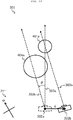
- FIG. 2 is a top view of the real space 201 at a time ta before a shift in orientation of the display device 100 and the user 202.
- FIG. 4 is a top view of the virtual space 301 at the time ta before the shift in orientation of the display device 100 and the user 202 in the real space 201.
- FIG. 3 is a top view of the real space 201 at a time tb after the shift in orientation of the display device 100 and the user 202.
- FIG. 5 is a top view of the virtual space 301 at the time t b after the shift in orientation of the display device 100 and the user 202 in the real space 201.
- the embodiment will be described with reference to these figures.
- the reference symbols in the figures are provided with lower case alphabets as required for representing the elapsed time from the time ta to the time tb, these lower case alphabets are omitted as required in the following description.
- the user 202 wears the display device 100 in front of the eyes in the real space 201. While the user 202 is wearing the display device 100, a display direction 203 of the display device 100 is opposite to a sight line direction of the user 202 looking at the display device 100.
- still or moving objects 401 to 404 are placed in the virtual space 301.
- the objects 402 and 403 remain still, while the object 401 moves in the direction of arrow A and the object 404 moves in the direction of arrow B in the virtual space 301.
- the objects 401 to 404 are generated by computer graphics.
- the positions of the objects 401 to 404 in the virtual space 301, their sizes, and shapes, and the moving velocities of the objects 401 and 404 are defined in advance.
- examples of the objects 401 and 404 include trains and people moving on the station platform, while examples of the objects 402 and 403 include columns and signboards standing still on the station platform.
- an orientation 211 in the real space 201 may be identical to or deviated from an orientation 311 in the virtual space 301. These orientations are deviated from each other in this embodiment.
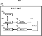
- FIG. 6 is a schematic block diagram illustrating a functional configuration of the display device 100 according to the embodiment of the disclosure.
- the display device 100 includes a detector 111, a changer 112, a generator 113, a specifier 114, a display controller 115, and a display 104.
- the detector 111 detects a shift in orientation of the display device 100 in the real space 201.
- the detector 111 detects a shift in the display direction 203 of the display device 100 relative to the reference axis in the real space 201 on the basis of the values measured by the sensor unit 105.
- a typical example of the reference axis in the real space 201 is the gravity direction in the real space 201 or the up-down direction of the display 104 of the display device 100.
- the functions of the detector 111 are performed by cooperation of the control unit 101 and the sensor unit 105.
- the changer 112 changes the sight line direction 303 in the virtual space 301 in accordance with the shift in orientation of the display device 100 detected by the detector 111. For example, the changer 112 acquires a rotational angle ⁇ about the reference axis in the real space 201 with reference to the shift in the display direction 203 of the display device 100 from the time t a until the time t b detected by the detector 111. Specifically, before the user 202 turns the head, the display direction 203a extends from the display device 100a to the user 202a as illustrated in FIG. 2 . After the user 202 turns the head, the display direction 203b extends from the display device 100b to the user 202b as illustrated in FIG. 3 .
- the angle between the display direction 203a and the display direction 203b is defined as the rotational angle ⁇ about the reference axis.
- the rotational angle ⁇ corresponds to a so-called yaw angle.
- the user 202 turns the head to the left in FIG. 3 .
- the interval between the time ta and the time tb can be defined depending on the usage.
- the interval may be a refresh interval (for example, vertical synchronization period) of the display 104 of the display device 100. Since the operation is repeated as explained below, the time tb in a certain repeating unit is regarded as the time ta in the subsequent repeating unit.
- the changer 112 rotates the sight line direction 303a by the rotational angle ⁇ about the reference axis at the observation site 302a in the virtual space 301, thereby updating the sight line direction 303a to the sight line direction 303b.
- the functions of the changer 112 are performed by the control unit 101.
- the generator 113 generates an image representing a view of the virtual space 301 from the observation site 302 in the sight line direction 303.
- the generator 113 uses a technique, such as perspective projection, to generate the image representing the view from the observation site 302 in the sight line direction 303, on the basis of the certain positions and shapes of the objects 401 to 404 in the virtual space 301.
- the specifier 114 specifies at least one focus object determined on a predetermined basis to have a low value of the velocity component, which is not resulting from movement of each of the objects 401 to 404 in the virtual space 301, in the inter-image velocity of the object transferred from one position to another position in respective images generated by the generator 113.
- FIG. 7A illustrates an image 501a representing a view of the virtual space 301 from the observation site 302 in the sight line direction 303 at the time ta.
- FIG. 7B illustrates an image 501b representing a view of the virtual space 301 from the observation site 302 in the sight line direction 303 at the time tb.
- each of the still objects 402 and 403 in the virtual space 301 among the objects 401 to 404 is transferred from one position in the generated image 501a to another position in the generated image 501b at an inter-image velocity equal to a velocity component resulting from the change in the sight line direction 303.
- the object 402 is transferred from one position in the generated image 501a to another position in the generated image 501b at an inter-image velocity V2 equal to a velocity component S2x resulting from the change in the sight line direction 303.
- each of the objects 401 and 404 moving in the virtual space 301 is transferred from one position to another position in the respective generated images at an inter-image velocity, which is equal to the resultant velocity from the velocity component resulting from the change in the sight line direction 303 and the velocity component resulting from the movement of the object.
- the object 401 is transferred from one position in the generated image 501a to another position in the generated image 501b at an inter-image velocity V1, which is equal to the resultant velocity from the velocity component S1x resulting from the change in the sight line direction 303 and the velocity component Ax resulting from the movement of the object.
- the focus object to which the user pays attention is expected to have a lower velocity component resulting from the change in the sight line direction 303, that is, a lower velocity component not resulting from the movement of the focus object in the inter-image velocity in comparison to that of the other objects, regardless of the change in the sight line direction 303.
- the focus object determined on a predetermined basis to have a low value of the velocity component not resulting from the movement of the object is specified among the objects.
- the specifier 114 acquires preceding and subsequent positions for each of the objects 401 to 404.
- the preceding position indicates the position of the object in the virtual space 301 immediately before the change in the sight line direction 303 in the image generated immediately before the change in the sight line direction 303.
- the subsequent position indicates the position of the object in the image to be generated immediately after the change in the sight line direction 303. More specifically, the specifier 114 calculates preceding positions based on the known positions and moving velocities of the objects 401 to 404 in the virtual space 301, the observation site 302, and the sight line direction 303. The specifier 114 also calculates subsequent positions based on the preceding positions, the transferred observation site 302, and the changed sight line direction 303.
- the specifier 114 then calculates the difference between the subsequent and preceding positions, as the velocity component resulting from the change in the sight line direction 303, that is, the velocity component not resulting from movement of each object. It should be noted that the specifier 114 regards the positions of the representative points (for example, geometric centers or gravitational centers) of the objects 401 to 404 as the positions of the objects 401 to 404.
- the object 401 is assumed to be located at a point Pa at the time ta as illustrated in FIG. 4 .
- the specifier 114 calculates the position Pia of the point Pa in the image 501a generated at the time ta, based on the point Pa, the observation site 302, and the sight line direction 303.
- the specifier 114 also calculates the position Pib of the point Pa in the image 501b to be generated at the time tb, based on the point Pa, the observation site 302 at the time tb, and the sight line direction 303 at the time tb.
- the specifier 114 then calculates the difference between the positions Pib and Pia, as the velocity component S1x resulting from the change in the sight line direction 303. That is, the specifier 114 calculates an inter-image velocity by subtracting the position Pib from the position Pia on the assumption that object 401 remains still, as the velocity component S1x resulting from the change in the sight line direction 303. The specifier 114 calculates a velocity component resulting from the change in the sight line direction 303 for each of the objects 401 to 404 in the virtual space 301 in the same manner.
- the specifier 114 determines whether the velocity component not resulting from the movement of the object is a low value or not on the predetermined basis. In an exemplary method of determining whether the velocity component not resulting from the movement of the object is a low value or not on the predetermined basis, the specifier 114 determines the minimum value of the velocity components resulting from the change in the sight line direction 303 calculated for the individual objects 401 to 404 to be a low value on the predetermined basis. The specifier 114 then specifies at least one focus object among the objects 401 to 404 having the minimum value of the velocity component resulting from the change in the sight line direction 303.
- the specifier 114 determines the object 401 to be a focus object.
- the specifier 114 may determine the velocity component to be a low value on a predetermined basis if the velocity component resulting from the change in the sight line direction 303 is a predetermined threshold or less or is less than a predetermined threshold.
- the specifier 114 may determine the velocity component to be a low value on a predetermined basis if the ratio of the velocity component to the detected change in the sight line direction 303 is less than a predetermined threshold.
- the specifier 114 may determine the velocity component to be a low value on a predetermined basis if the value, which is calculated by dividing the velocity component resulting from the change in the sight line direction 303 by the velocity of the detected change in the sight line direction 303, is less than a predetermined threshold.
- the functions of the specifier 114 are performed by the control unit 101.
- the generator 113 increases the transparency of a hiding object, which is an object other than the focus object specified by the specifier 114 among the objects 401 to 404 and which hides the focus object in a view of the virtual space 301 in the sight line direction 303, and then generates an image. For example, the generator 113 renders the background with a certain background color (for example, black) and then renders the objects in the descending order of distance from the observation site 302. If the pixels to represent an object other than the focus object have been provided with a color other than the background color, the generator 113 determines that these pixels have already been provided with the color of the focus object, that is, these pixels correspond to the focus object hidden behind the other object. The generator 113 then determines the other object to be the object hiding the focus object.
- a hiding object which is an object other than the focus object specified by the specifier 114 among the objects 401 to 404 and which hides the focus object in a view of the virtual space 301 in the sight line direction 303, and then generates an image.
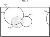
- the generator 113 increases the transparency of the other object and then generates an image. For example, if the specifier 114 determines the object 401 to be the focus object, the generator 113 determines the object 402 to be the object hiding the object 401. The generator 113 then increases the transparency of the object 402 as illustrated in FIG. 9 and then generates the image 501b. The generator 113 increases the transparency of the object 402 and is thus able to generate an image having a high visibility of the portion of the object 401 focused by the user but hidden behind the object 402. In the case where a focus object is hidden behind another focus object, the generator 113 generates an image without increasing the transparency of the other focus object hiding the focus object.
- the functions of the generator 113 are performed by the control unit 101.
- the display controller 115 causes the image generated by the generator 113 to be displayed on the display 104.
- the display controller 115 causes the image 501a illustrated in FIG. 7A at the time ta and the image 501b illustrated in FIG. 9 at the time t b to be individually displayed on the display 104.
- the functions of the display controller 115 are performed by the control unit 101.
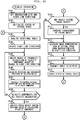
- FIG. 10 is a flowchart of a display operation executed by the control unit 101 of the display device 100. This operation is activated by, for example, reception of an instruction to start this operation by the operation unit 106.
- the display device 100 sets the observation site 302 and the sight line direction 303 to be the predetermined initial states in the virtual space 301 (Step S101).
- the display device 100 then initializes the status of the virtual space 301 (Step S102).
- the display device 100 obtains and sets the positions, shapes, orientations, and appearances of objects to be placed in the virtual space 301, and obtains and sets an image of the background supposed to be placed at an infinite distance in the virtual space 301, for example.
- the display device 100 then detects the orientation of the display device 100, and acquires the rotational angle ⁇ of the display direction of the display 104 about the reference axis in the real space 201 (Step S103). Since Step S103 is repetitively executed, the acquired rotational angle ⁇ is equivalent to the difference between the display direction 203 previously measured by a sensor or the like and the currently measured display direction 203.
- the display device 100 then updates the sight line direction 303 depending on the acquired rotational angle ⁇ (Step S104).
- the display device 100 selects one of the objects 401 to 404 in the virtual space 301 for which the velocity component resulting from the change in the sight line direction 303 has not yet calculated (Step S105).
- the display device 100 then calculates the preceding and subsequent positions of the object selected in Step S105 (Step S106).
- the display device 100 then calculates the difference between the subsequent and preceding positions calculated in Step S106 as the velocity component resulting from the change in the sight line direction 303 for the selected object (Step S107). The display device 100 then determines whether the velocity components resulting from the change in the sight line direction 303 have been calculated for all the objects 401 to 404 (Step S108). If calculation of the velocity components resulting from by the change in the sight line direction 303 for all the objects 401 to 404 has not yet been completed (Step S108; No), the display device 100 returns to Step S105.
- Step S108 If calculation of the velocity components resulting from the change in the sight line direction 303 for all the objects 401 to 404 has been completed (Step S108; Yes), the display device 100 specifies a focus object having the minimum value of the calculated velocity components (Step S109).
- the display device 100 determines whether any object hides the focus object specified in Step S109 (Step S110). If no object hides the focus object (Step S110; No), the display device 100 proceeds to Step S112.
- Step S110 If any object hides the focus object (Step S110; Yes), the display device 100 increases the transparency of the object hiding the focus object by a predetermined degree (Step S111).
- the display device 100 then generates an image representing a view of the virtual space 301 from the observation site 302 in the sight line direction 303 (Step S112).
- the display device 100 then waits until a vertical synchronization interrupt of the display 104 (Step S113), and transmits the generated image to the display 104 to exhibit the image to the user (Step S114).
- the display device 100 then updates the status of the virtual space 301 (Step S115). For example, in the virtual space 301 generated by computer graphics that vary with time, the display device 100 executes a physical simulation for updating the position and orientation of an object using the parameters (for example, velocity, acceleration, angular velocity, and angular acceleration) set in the object, and deforms the object under predetermined conditions.
- the parameters for example, velocity, acceleration, angular velocity, and angular acceleration
- the display device 100 then returns to Step S103.
- the display device 100 repeats the above-explained operation, for example, until receiving an instruction to end this operation by the operation unit 106.
- the repetition period of this operation accords with the vertical synchronization period because of the waiting step (Step S113).
- the display device 100 changes the sight line direction 303 in the virtual space 301 in response to a shift in orientation of the display device 100 in the real space 201.
- the display device 100 specifies at least one focus object determined on a predetermined basis to have a low value of the velocity component, which is not resulting from the movement of each of the objects 401 to 404 in the virtual space 301, in the inter-image velocity of the object.
- This configuration enables the display device 100 to specify a focus object of which the movement is being followed by the user's eyes in the virtual space 301, by detection of a shift in orientation of the display device 100 without detection of the position of the display device 100.
- the display device 100 increases the transparency of the object hiding the focus object and then generates an image.
- the display device 100 can therefore make the portion of the focus object hidden behind the other object visible.
- the display device 100 may enable the user to look into a space behind an obstacle for a focus object by changing the observation site 302 in accordance with the change in the sight line direction 303.
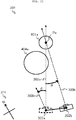
- the example illustrated in FIG. 11 assumes that a portion of the focus object 401a is hidden behind the object 404a when the user looks at the focus object 401a from the observation site 302a in the sight line direction 303a.
- the user is likely to turn and move the head in the real space 201 to look into a space behind the object 404a for the portion of the focus object 401a.
- the display device 100 without an ability to detect the position of the display device 100 cannot detect the movement of the head of the user.
- the display device 100 may detect a turn of the head, that is, a shift in orientation of the display device 100, change the sight line direction 303a in the virtual space 301 in accordance with the shift in orientation, and transfer the observation site 302a in accordance with the change in the sight line direction 303a.
- the changer 112 may change the observation site 302 toward the direction opposite to the direction of change in the sight line direction 303, in accordance with the change in the sight line direction 303. For example, if the user turns the head in the counterclockwise direction by a rotational angle ⁇ from the state illustrated in FIG. 2 at the time ta to the state illustrated in FIG. 3 at the time tb, the changer 112 acquires the rotational angle ⁇ about the reference axis in the real space 201 based on the shift in the display direction 203 of the display device 100 detected by the detector 111. As illustrated in FIG.
- the changer 112 then rotates the sight line direction 303a by the rotational angle ⁇ about the reference axis at the observation site 302a in the virtual space 301, thereby updating the sight line direction 303a to the sight line direction 303b.
- the changer 112 also transfers the observation site 302a such that the observation site 302a rotates by the rotational angle ⁇ about the point Pa of the focus object 401a specified by the specifier 114 toward the direction opposite to the direction of change in the sight line direction 303, thereby updating the observation site 302a to the observation site 302b.
- the changer 112 since the sight line direction 303a is rotated in the counterclockwise direction to become the sight line direction 303b, the changer 112 conducts rotational transfer of the observation site 302a in the clockwise direction by the rotational angle ⁇ to obtain the observation site 302b.
- This configuration enables the display device 100 to transfer the observation site 302 toward the direction opposite to the direction of change in the sight line direction 303 in accordance with the change in the sight line direction 303, thereby updating the observation site 302 to an observation site appropriate for looking into a space for the focus object while bringing a reduced feeling of strangeness to the user 202, even if the display device 100 has no ability to detect the position of the display device 100.
- the changer 112 transfers the observation site 302 toward the direction opposite to the direction of change in the sight line direction 303 about one of the focus objects having the minimum value of the velocity component not resulting from the movement of the object, that is, the minimum value of the velocity component resulting from the change in the sight line direction 303.
- the angle of rotation of the observation site 302 by the changer 112 toward the direction opposite to the direction of change in the sight line direction 303 is not necessarily be equal to the rotational angle ⁇ of the sight line direction 303.
- the changer 112 may transfer the observation site 302 by a rotational angle proportional to the rotational angle ⁇ of the sight line direction 303 toward the direction opposite to the direction of change in the sight line direction 303.
- the display device 100 detects a shift in orientation of the display device 100 and specifies a focus object based on the shift.
- the display device 100 may further have an ability to detect the position of the display device 100.
- the changer 112 may transfer the observation site 302 in the virtual space 301 in accordance with the detected position of the display device 100.
- the changer 112 acquires a displacement d from the time t a until the time t b of a position 204 of the display device 100 detected by the detector 111.
- the representative point for example, geometric center or gravitational center
- the representative point of the display device 100 is located at the position 204a before the user 202 turns the head, as illustrated in FIG. 12 .
- the representative point of the display device 100 is located at the position 204b after the user 202 turns the head, as illustrated in FIG. 12 .
- the displacement d of the display device 100 therefore corresponds to the difference vector between the positions 204a and 204b.
- the changer 112 transfers the observation site 302a by the displacement d in the virtual space 301, thereby updating the observation site 302a to the observation site 302b.
- the generator 113 then generates an image representing a view of the virtual space 301 from the observation site 302b in the sight line direction 303b.
- the specifier 114 then specifies the focus object determined on a predetermined basis to have a low value of the velocity component, which is not resulting from the movement of the object, in the inter-image velocity of the object transferred from one position to another position in the respective images generated by the generator 113, as in the above-described embodiment.
- a display device 100 capable of detecting not only the orientation but also the position of the display device 100 is expected to specify a focus object at the intersection of the previous and current sight line directions 303, assuming that the user changes the sight line direction while capturing the focus object at the center of the view.
- the display device 100 having a low accuracy of detecting the orientation and position of the display device 100 possibly fails to properly determine the intersection.
- the disclosed specifier 114 specifies the focus object determined on a predetermined basis to have a low value of the velocity component, which is not resulting from the movement of the object, in the inter-image velocity of the object transferred from one position to another position in the respective images generated by the generator 113, and can therefore specify the focus object despite of a low accuracy of detecting the orientation and position of the display device 100.
- the display device 100 specifies a focus object in response to detection of a shift in orientation of the display device 100. That is, the display device 100 stops specification of a focus object while the display device 100 is maintaining the orientation in the above-described embodiment.
- the display device 100 may specify the most lately specified focus object again, for example, for a predetermined period from the most lately detection of a shift in orientation of the display device 100. No detection of a shift in orientation of the display device 100 seems to occur because the user has already turned the display device 100 to the direction appropriate for observation of the focus object.
- the display device 100 can thus specify the most lately specified focus object again for a predetermined period from the most lately detection of a shift in orientation of the display device 100, despite of no detection of a shift in orientation of the display device 100.
- the specifier 114 specifies the focus object having the minimum value of the velocity component, which is not resulting from the movement of the object, in the inter-image velocity of the object transferred from one position to another position in the respective images generated by the generator 113.
- the specifier 114 specifies a single focus object
- the focus object may be frequently switched in some situations.
- the display device 100 may stop specification of another focus object for a predetermined period from specification of one focus object.
- the display device 100 detects a shift in yaw angle as a shift in orientation of the display device 100 in the above-described embodiment, this configuration should not be construed as limiting the invention.
- the display device 100 may also detect, for example, a shift in roll or pitch angle as a shift in orientation of the display device 100.
- the above-described functions of the display device 100 may be achieved by hardware including various electric and electronic devices. Alternatively, these functions may be achieved by, for example, electric and electronic circuits and controllers installed in an existing personal computer or information terminal, to configure the display device 100.
- the display 104 and the sensor unit 105 of the display device 100 may be configured by a head mounted display, and the display control device including the control unit 101, the ROM 102, and the RAM 103 of the display device 100 may be configured by a personal computer or information terminal connected to the head mounted display, for example.
- the functions of the display device 100 may be achieved by an existing personal computer or information terminal by installation of a program for providing the functional configuration of the display device 100 demonstrated in the above embodiment and by execution of the program in a CPU or the like that controls the personal computer or information terminal.
- the CPU or the like executes the program and can thus perform the display control method for controlling the display device 100.
- This program may be applied in any procedure other than the above example.
- the program may be stored in a non-transitory computer-readable recording medium, such as a compact disc read-only memory (CD-ROM), digital versatile disc (DVD), or magneto optical disc (MO), for example.
- the program may be stored in a storage on a network, such as the Internet to be downloaded.
- a display control device controls a display device and includes: a changer configured to change a sight line direction in a virtual space, which includes a plurality of still and moving objects in accordance with a shift in orientation of the display device in a real space; a generator configured to generate an image representing a view of the virtual space in the sight line direction; a display controller configured to cause the generated image to be displayed on a display included in the display device; and a specifier configured to specify a focus object among the objects.
- the changer transfers an observation site about the focus object toward a direction opposite to a direction of change in the sight line direction.
- the generator generates the image representing a view of the virtual space from the observation site in the sight line direction.
- the specifier may specify the focus object determined on a predetermined basis to have a low value of the velocity component, which is not resulting from movement of the object in the virtual space, in an inter-image velocity of the object transferred from one position to another position in respective images.
- the changer may transfer the observation site about one of the focus objects having a minimum value of the velocity component.
- the specifier may acquire a preceding position and a subsequent position for each of the objects, the preceding position being a position of the object in the virtual space immediately before the change in the sight line direction in an image generated immediately before the change in the sight line direction, the subsequent position being a position of the object in an image to be generated immediately after the change in the sight line direction.
- the specifier may use a difference between the subsequent position and the preceding position as the velocity component of the object.
- the object having a minimum value of the velocity component may be determined on the predetermined basis to have a low value.
- the object having the velocity component of a predetermined threshold or less may be determined on the predetermined basis to have a low value.
- the object having the velocity component of which a ratio to the shift in orientation is less than a predetermined threshold may be determined on the predetermined basis to have a low value.
- the changer may transfer the observation site in accordance with the change in the sight line direction.
- the changer may transfer the observation site at an amount in proportion to an amount of the change in the sight line direction.
- the generator may increase a transparency of another object other than the focus object among the objects, the other object hiding the focus object in a view of the virtual space in the sight line direction, and then generate an image.
- a display control method is performed by a display control device for controlling a display device.
- the method includes: a changing step of changing a sight line direction in a virtual space, which includes a plurality of still and moving objects, by the display control device in accordance with a shift in orientation of the display device in a real space; a generating step of generating an image representing a view of the virtual space in the sight line direction by the display control device; a displaying step of causing the generated image to be displayed on a display included in the display device by the display control device; and a specifying step of specifying a focus object among the objects by the display control device.
- An observation site is transferred about the focus object toward a direction opposite to a direction of change in the sight line direction in the changing step.
- the image representing a view of the virtual space from the observation site in the sight line direction is generated in the generating step.
- a program causes a computer to function as: a changer configured to change a sight line direction in a virtual space, which includes a plurality of still and moving objects, in accordance with a shift in orientation of a display device in a real space; a generator configured to generate an image representing a view of the virtual space in the sight line direction; a display controller configured to cause the generated image to be displayed on a display included in the display device; and a specifier configured to specify a focus object among the objects.
- the changer transfers an observation site about the focus object toward a direction opposite to a direction of change in the sight line direction.
- the generator generates the image representing a view of the virtual space from the observation site in the sight line direction.
- a non-transitory computer-readable information recording medium stores a program thereon.
- the program causes a computer to function as: a changer configured to change a sight line direction in a virtual space, which includes a plurality of still and moving objects, in accordance with a shift in orientation of a display device in a real space; a generator configured to generate an image representing a view of the virtual space in the sight line direction; a display controller configured to cause the generated image to be displayed on a display included in the display device; and a specifier configured to specify a focus object among the objects.
- the changer transfers an observation site about the focus object toward a direction opposite to a direction of change in the sight line direction.
- the generator generates an image representing a view of the virtual space from the observation site in the sight line direction.
- the disclosure can provide a display control device that causes a display device to display a view of a virtual space or the like from an observation site in the virtual space or the like and appropriately transfers the observation site in the virtual space or the like without detection of the position of the display device in a real space, and can provide a display control method, a program, and a non-transitory computer-readable information recording medium.
Landscapes
- Engineering & Computer Science (AREA)
- Theoretical Computer Science (AREA)
- Physics & Mathematics (AREA)
- General Physics & Mathematics (AREA)
- General Engineering & Computer Science (AREA)
- Human Computer Interaction (AREA)
- Signal Processing (AREA)
- Multimedia (AREA)
- Computer Graphics (AREA)
- Computer Hardware Design (AREA)
- Optics & Photonics (AREA)
- Computing Systems (AREA)
- Geometry (AREA)
- Software Systems (AREA)
- User Interface Of Digital Computer (AREA)
- Controls And Circuits For Display Device (AREA)
- Processing Or Creating Images (AREA)
Abstract
Description
- The present disclosure relates to a display control device, a display control method, a program, and a non-transitory computer-readable information recording medium.
- Some methods have been known for displaying an area or object that is hidden behind an obstacle and is hardly visible when viewed from a user. For example,
Patent Literature 1 discloses a method of taking an image of a blind area of a driver with a camera, converting the taken image into an image from the view point of the driver, and displaying the resulting image and a translucent image of a vehicle from the view point of the driver in a superimposed manner. - Patent Literature 1: Unexamined
Japanese Patent Application Kokai Publication No. 2010-114618 - In some techniques related to a virtual reality system, augmented reality system, or substitutional reality system, the system detects the orientation of a user wearing a head mounted display, changes the sight line direction in a three-dimensional space in accordance with the detected orientation, generates an image representing a view of the three-dimensional space in the sight line direction, and causes the image to be displayed on the head mounted display. In the technique disclosed in
Patent Literature 1, the image of the blind area and the translucent image of the vehicle are displayed in a superimposed manner on the preliminary assumption that the driver pays attention to the blind area of the driver. - If a display device has an ability to detect the position of the display device, a system is capable of display control by transferring the observation site in the virtual space in accordance with movement of the head of a user. This configuration enables the user to observe a portion of an object hidden behind another object, for example, when the user moves the head so as to look into the space behind the other object for the hidden portion.
- Unfortunately, if the display device has no ability to detect the position of the display device in the real space, the system is incapable of display control in accordance with movement of the user's head and thus cannot achieve observation of the hidden portion. If the display device has an ability to detect the position of the display device in the real space with a low detection accuracy, the system may fail to transfer the observation site to an appropriate site and cannot achieve appropriate observation of the hidden portion.
- The disclosure, which has been accomplished to solve the above issues, is to provide a display control device that causes a display device to display a view of a virtual space or the like from an observation site in the virtual space or the like and appropriately transfers the observation site in the virtual space or the like without detection of the position of the display device in a real space, and to provide a display control method, a program, and a non-transitory computer-readable information recording medium.
- A display control device according to one aspect of the disclosure for solving the above issues controls a display device. The display control device: changes a sight line direction in a virtual space, which includes a plurality of still and moving objects, in accordance with a shift in orientation of the display device in a real space; generates an image representing a view of the virtual space in the sight line direction; and causes the generated image to be displayed on a display included in the display device. The display control device specifies a focus object among the objects, transfers an observation site about the focus object toward a direction opposite to a direction of change in the sight line direction, and generates the image representing a view of the virtual space from the observation site in the sight line direction.
- A display control method performed by the above-described display control device can be achieved when a computer connected to or integrated with the display device executes a program stored on a non-transitory computer-readable information recording medium or the like and functions as the display control device for controlling the display device.
- This non-transitory information recording medium can be distributed and sold independently from computers. The non-transitory information recording medium indicates a tangible information recording medium. Examples of the non-transitory information recording medium include a compact disk, flexible disk, hard disk, magnetic disk, digital video disk, magnetic tape, and semiconductor memory. In contrast, a transitory information recording medium indicates a transmission medium (transmission signal) itself. Examples of the transitory recording medium include an electrical signal, optical signal, and electromagnetic wave. A temporary storage area indicates an area for temporarily storing data and programs. A typical example of the temporary storage area is a volatile memory, such as a random access memory (RAM).
- According to the disclosure, a display control device, which causes a display device to display a view of a virtual space or the like from an observation site in the virtual space or the like, can appropriately transfer the observation site in the virtual space or the like without detection of the position of the display device in a real space.
-
-
FIG. 1 is a schematic block diagram illustrating a hardware configuration of a display device according to an embodiment; -
FIG. 2 is a top view of a real space before a shift in orientation of a display device and a user; -
FIG. 3 is a top view of the real space after the shift in orientation of the display device and the user; -
FIG. 4 is a top view of a virtual space before the shift in orientation of the display device and the user in the real space; -
FIG. 5 is a top view of the virtual space after the shift in orientation of the display device and the user in the real space; -
FIG. 6 is a schematic block diagram illustrating a functional configuration of the display device according to the embodiment; -
FIG. 7A illustrates an image representing a view of the virtual space from an observation site in a sight line direction before the shift in orientation of the display device and the user in the real space; -
FIG. 7B illustrates an image representing a view of the virtual space from the observation site in the sight line direction after the shift in orientation of the display device and the user in the real space; -
FIG. 8 is a diagram for explaining a method of calculating a velocity component resulting from a change in the sight line direction; -
FIG. 9 illustrates an image representing a view of the virtual space from the observation site in the sight line direction after the shift in orientation of the display device and the user in the real space; -
FIG. 10 is a flowchart of a display operation executed by a control unit of the display device according to the embodiment; -
FIG. 11 is a top view of a virtual space after a shift in orientation of a display device and a user in a real space according to a modification; -
FIG. 12 is a top view of a real space after a shift in orientation and position of a display device and a user according to another modification; and -
FIG. 13 is a top view of a virtual space after the shift in direction and position of the display device and the user in the real space according to the other modification. - An embodiment of the disclosure will now be described. This embodiment is provided for exemplary purposes only and does not limit the scope of the disclosure. Persons skilled in the art can replace some or all of the components of the embodiment with their equivalents to configure other embodiments, which are also encompassed in the scope of the disclosure. The embodiment of the disclosure will now be described with reference to the accompanying drawings, in which the identical or corresponding components are provided with the same reference symbol.
-
FIG. 1 is a schematic block diagram illustrating a hardware configuration of adisplay device 100 according to the embodiment. Thedisplay device 100 includes, for example, a head mounted display equipped with various sensors and controllers. - The head mounted display may be provided with a computer (for example, smartphone, tablet computer, or phablet) installed in an attachment of the head mount display. In this case, the
display device 100 is achieved by execution of a program in the computer (for example, smartphone) for causing the computer to function as the above-described components. - Alternatively, the
display device 100 may be configured by a head mounted display equipped with various sensors and a display screen and a computer connected to the head mounted display via wire or wireless communication for controlling the head mounted display. In this case, the computer acquires values measured by the sensors from the head mounted display, generates an image based on the measured values, and causes the image to be displayed on the display screen of the head mounted display. - With reference to
FIG. 1 , thedisplay device 100 is composed of acontrol unit 101, a read only memory (ROM) 102, aRAM 103, adisplay 104, asensor unit 105, and anoperation unit 106. These components are connected to each other viabuses 107. - The
control unit 101 includes, for example, a central processing unit (CPU) and controls theentire display device 100. - The
ROM 102 is a non-volatile memory that stores programs and various types of data for enabling thecontrol unit 101 to control theentire display device 100. - The
RAM 103 is a volatile memory that temporarily stores information generated by thecontrol unit 101 and data necessary for generation of the information. - The
display 104 includes a liquid crystal display (LCD) and backlights. Thedisplay 104 displays, for example, an image output from thecontrol unit 101 under the control of thecontrol unit 101. - The
sensor unit 105 is equipped with an orientation sensor and an acceleration sensor to detect the orientation of thedisplay device 100, that is, the orientation of thedisplay 104. Thesensor unit 105 may detect a shift in orientation instead of detecting the orientation itself. - The
operation unit 106 includes input components, such as buttons, a keyboard, and a touch panel. Theoperation unit 106 receives an operation input from a user of thedisplay device 100 and outputs a signal corresponding to the received operation to thecontrol unit 101. - In the above example, the display control device according to the embodiment is configured by the
control unit 101 that controls thedisplay device 100 in cooperation with theROM 102 and theRAM 103. Thedisplay device 100 is integrated with the display control device in such a manner as to include the display control device. - Alternatively, the
control unit 101, theROM 102, and theRAM 103 may be configured by an external computer communicably connected to a head mounted display. Thedisplay 104 and thesensor unit 105 may be the constituent elements of the head mounted display connected to this computer. Theoperation unit 106 may be input components connected to this computer. In this case, the display control device according to the embodiment is achieved outside the head mounted display by cooperation of thecontrol unit 101 with theROM 102 and theRAM 103. This display control device controls thedisplay device 100 including thedisplay 104 and thesensor unit 105 of the head mounted display. - The following description is directed to a positional relationship between the
display device 100 and a user 202 in areal space 201 and a virtual space (three-dimensional space) 301 displayed in thedisplay device 100 according to the embodiment.FIG. 2 is a top view of thereal space 201 at a time ta before a shift in orientation of thedisplay device 100 and the user 202.FIG. 4 is a top view of thevirtual space 301 at the time ta before the shift in orientation of thedisplay device 100 and the user 202 in thereal space 201.FIG. 3 is a top view of thereal space 201 at a time tb after the shift in orientation of thedisplay device 100 and the user 202.FIG. 5 is a top view of thevirtual space 301 at the time tb after the shift in orientation of thedisplay device 100 and the user 202 in thereal space 201. The embodiment will be described with reference to these figures. Although the reference symbols in the figures are provided with lower case alphabets as required for representing the elapsed time from the time ta to the time tb, these lower case alphabets are omitted as required in the following description. - With reference to
FIGS. 2 and3 , the user 202 wears thedisplay device 100 in front of the eyes in thereal space 201. While the user 202 is wearing thedisplay device 100, a display direction 203 of thedisplay device 100 is opposite to a sight line direction of the user 202 looking at thedisplay device 100. - With reference to
FIGS. 4 and5 , still or movingobjects 401 to 404 are placed in thevirtual space 301. In this embodiment, the objects 402 and 403 remain still, while theobject 401 moves in the direction of arrow A and the object 404 moves in the direction of arrow B in thevirtual space 301. Theobjects 401 to 404 are generated by computer graphics. The positions of theobjects 401 to 404 in thevirtual space 301, their sizes, and shapes, and the moving velocities of theobjects 401 and 404 are defined in advance. In an exemplary case where thedisplay device 100 displays a station platform reproduced by computer graphics, examples of theobjects 401 and 404 include trains and people moving on the station platform, while examples of the objects 402 and 403 include columns and signboards standing still on the station platform. - It should be noted that an
orientation 211 in thereal space 201 may be identical to or deviated from anorientation 311 in thevirtual space 301. These orientations are deviated from each other in this embodiment. -
FIG. 6 is a schematic block diagram illustrating a functional configuration of thedisplay device 100 according to the embodiment of the disclosure. As illustrated inFIG. 6 , thedisplay device 100 includes adetector 111, achanger 112, agenerator 113, aspecifier 114, adisplay controller 115, and adisplay 104. - The
detector 111 detects a shift in orientation of thedisplay device 100 in thereal space 201. For example, thedetector 111 detects a shift in the display direction 203 of thedisplay device 100 relative to the reference axis in thereal space 201 on the basis of the values measured by thesensor unit 105. A typical example of the reference axis in thereal space 201 is the gravity direction in thereal space 201 or the up-down direction of thedisplay 104 of thedisplay device 100. - In this embodiment, the functions of the
detector 111 are performed by cooperation of thecontrol unit 101 and thesensor unit 105. - The
changer 112 changes the sight line direction 303 in thevirtual space 301 in accordance with the shift in orientation of thedisplay device 100 detected by thedetector 111. For example, thechanger 112 acquires a rotational angle θ about the reference axis in thereal space 201 with reference to the shift in the display direction 203 of thedisplay device 100 from the time ta until the time tb detected by thedetector 111. Specifically, before the user 202 turns the head, thedisplay direction 203a extends from thedisplay device 100a to theuser 202a as illustrated inFIG. 2 . After the user 202 turns the head, thedisplay direction 203b extends from thedisplay device 100b to theuser 202b as illustrated inFIG. 3 . The angle between thedisplay direction 203a and thedisplay direction 203b is defined as the rotational angle θ about the reference axis. The rotational angle θ corresponds to a so-called yaw angle. The user 202 turns the head to the left inFIG. 3 . - The interval between the time ta and the time tb can be defined depending on the usage. For example, the interval may be a refresh interval (for example, vertical synchronization period) of the
display 104 of thedisplay device 100. Since the operation is repeated as explained below, the time tb in a certain repeating unit is regarded as the time ta in the subsequent repeating unit. - The
changer 112 rotates thesight line direction 303a by the rotational angle θ about the reference axis at theobservation site 302a in thevirtual space 301, thereby updating thesight line direction 303a to thesight line direction 303b. - In this embodiment, the functions of the
changer 112 are performed by thecontrol unit 101. - The
generator 113 generates an image representing a view of thevirtual space 301 from the observation site 302 in the sight line direction 303. For example, thegenerator 113 uses a technique, such as perspective projection, to generate the image representing the view from the observation site 302 in the sight line direction 303, on the basis of the certain positions and shapes of theobjects 401 to 404 in thevirtual space 301. - The
specifier 114 specifies at least one focus object determined on a predetermined basis to have a low value of the velocity component, which is not resulting from movement of each of theobjects 401 to 404 in thevirtual space 301, in the inter-image velocity of the object transferred from one position to another position in respective images generated by thegenerator 113. - The inter-image velocity and the velocity component not resulting from movement of an object will now be described with reference to
FIGS. 7A and7B .FIG. 7A illustrates animage 501a representing a view of thevirtual space 301 from the observation site 302 in the sight line direction 303 at the time ta.FIG. 7B illustrates animage 501b representing a view of thevirtual space 301 from the observation site 302 in the sight line direction 303 at the time tb. When the sight line direction 303 is changed, each of the still objects 402 and 403 in thevirtual space 301 among theobjects 401 to 404 is transferred from one position in the generatedimage 501a to another position in the generatedimage 501b at an inter-image velocity equal to a velocity component resulting from the change in the sight line direction 303. For example, the object 402 is transferred from one position in the generatedimage 501a to another position in the generatedimage 501b at an inter-image velocity V2 equal to a velocity component S2x resulting from the change in the sight line direction 303. In contrast, when the sight line direction 303 is changed, each of theobjects 401 and 404 moving in thevirtual space 301 is transferred from one position to another position in the respective generated images at an inter-image velocity, which is equal to the resultant velocity from the velocity component resulting from the change in the sight line direction 303 and the velocity component resulting from the movement of the object. For example, theobject 401 is transferred from one position in the generatedimage 501a to another position in the generatedimage 501b at an inter-image velocity V1, which is equal to the resultant velocity from the velocity component S1x resulting from the change in the sight line direction 303 and the velocity component Ax resulting from the movement of the object. In general, if a user pays attention to a moving object, the user is likely to change the sight line direction 303 in accordance with the movement of the object while capturing the object at the center of the view (that is, the center of the generated image). Accordingly, the focus object to which the user pays attention is expected to have a lower velocity component resulting from the change in the sight line direction 303, that is, a lower velocity component not resulting from the movement of the focus object in the inter-image velocity in comparison to that of the other objects, regardless of the change in the sight line direction 303. In this embodiment, the focus object determined on a predetermined basis to have a low value of the velocity component not resulting from the movement of the object is specified among the objects. - Specifically, the
specifier 114 acquires preceding and subsequent positions for each of theobjects 401 to 404. The preceding position indicates the position of the object in thevirtual space 301 immediately before the change in the sight line direction 303 in the image generated immediately before the change in the sight line direction 303. The subsequent position indicates the position of the object in the image to be generated immediately after the change in the sight line direction 303. More specifically, thespecifier 114 calculates preceding positions based on the known positions and moving velocities of theobjects 401 to 404 in thevirtual space 301, the observation site 302, and the sight line direction 303. Thespecifier 114 also calculates subsequent positions based on the preceding positions, the transferred observation site 302, and the changed sight line direction 303. Thespecifier 114 then calculates the difference between the subsequent and preceding positions, as the velocity component resulting from the change in the sight line direction 303, that is, the velocity component not resulting from movement of each object. It should be noted that thespecifier 114 regards the positions of the representative points (for example, geometric centers or gravitational centers) of theobjects 401 to 404 as the positions of theobjects 401 to 404. - A method of calculating the velocity component resulting from the change in the sight line direction 303 will now be explained focusing on the
object 401 with reference toFIG. 8 . For example, theobject 401 is assumed to be located at a point Pa at the time ta as illustrated inFIG. 4 . In this case, thespecifier 114 calculates the position Pia of the point Pa in theimage 501a generated at the time ta, based on the point Pa, the observation site 302, and the sight line direction 303. Thespecifier 114 also calculates the position Pib of the point Pa in theimage 501b to be generated at the time tb, based on the point Pa, the observation site 302 at the time tb, and the sight line direction 303 at the time tb. Thespecifier 114 then calculates the difference between the positions Pib and Pia, as the velocity component S1x resulting from the change in the sight line direction 303. That is, thespecifier 114 calculates an inter-image velocity by subtracting the position Pib from the position Pia on the assumption that object 401 remains still, as the velocity component S1x resulting from the change in the sight line direction 303. Thespecifier 114 calculates a velocity component resulting from the change in the sight line direction 303 for each of theobjects 401 to 404 in thevirtual space 301 in the same manner. - The
specifier 114 then determines whether the velocity component not resulting from the movement of the object is a low value or not on the predetermined basis. In an exemplary method of determining whether the velocity component not resulting from the movement of the object is a low value or not on the predetermined basis, thespecifier 114 determines the minimum value of the velocity components resulting from the change in the sight line direction 303 calculated for theindividual objects 401 to 404 to be a low value on the predetermined basis. Thespecifier 114 then specifies at least one focus object among theobjects 401 to 404 having the minimum value of the velocity component resulting from the change in the sight line direction 303. For example, when theobject 401 has the minimum velocity component S1x of the velocity components of theobjects 401 to 404 resulting from the change in the sight line direction 303, thespecifier 114 determines theobject 401 to be a focus object. Alternatively, thespecifier 114 may determine the velocity component to be a low value on a predetermined basis if the velocity component resulting from the change in the sight line direction 303 is a predetermined threshold or less or is less than a predetermined threshold. Alternatively, thespecifier 114 may determine the velocity component to be a low value on a predetermined basis if the ratio of the velocity component to the detected change in the sight line direction 303 is less than a predetermined threshold. Specifically, thespecifier 114 may determine the velocity component to be a low value on a predetermined basis if the value, which is calculated by dividing the velocity component resulting from the change in the sight line direction 303 by the velocity of the detected change in the sight line direction 303, is less than a predetermined threshold. - In this embodiment, the functions of the
specifier 114 are performed by thecontrol unit 101. - The
generator 113 increases the transparency of a hiding object, which is an object other than the focus object specified by thespecifier 114 among theobjects 401 to 404 and which hides the focus object in a view of thevirtual space 301 in the sight line direction 303, and then generates an image. For example, thegenerator 113 renders the background with a certain background color (for example, black) and then renders the objects in the descending order of distance from the observation site 302. If the pixels to represent an object other than the focus object have been provided with a color other than the background color, thegenerator 113 determines that these pixels have already been provided with the color of the focus object, that is, these pixels correspond to the focus object hidden behind the other object. Thegenerator 113 then determines the other object to be the object hiding the focus object. Thegenerator 113 increases the transparency of the other object and then generates an image. For example, if thespecifier 114 determines theobject 401 to be the focus object, thegenerator 113 determines the object 402 to be the object hiding theobject 401. Thegenerator 113 then increases the transparency of the object 402 as illustrated inFIG. 9 and then generates theimage 501b. Thegenerator 113 increases the transparency of the object 402 and is thus able to generate an image having a high visibility of the portion of theobject 401 focused by the user but hidden behind the object 402. In the case where a focus object is hidden behind another focus object, thegenerator 113 generates an image without increasing the transparency of the other focus object hiding the focus object. - In this embodiment, the functions of the
generator 113 are performed by thecontrol unit 101. - The
display controller 115 causes the image generated by thegenerator 113 to be displayed on thedisplay 104. For example, thedisplay controller 115 causes theimage 501a illustrated inFIG. 7A at the time ta and theimage 501b illustrated inFIG. 9 at the time tb to be individually displayed on thedisplay 104. - In this embodiment, the functions of the
display controller 115 are performed by thecontrol unit 101. - The operation of the
display device 100 according to the embodiment of the disclosure will now be explained.FIG. 10 is a flowchart of a display operation executed by thecontrol unit 101 of thedisplay device 100. This operation is activated by, for example, reception of an instruction to start this operation by theoperation unit 106. - First, the
display device 100 sets the observation site 302 and the sight line direction 303 to be the predetermined initial states in the virtual space 301 (Step S101). - The
display device 100 then initializes the status of the virtual space 301 (Step S102). In this initialization step, thedisplay device 100 obtains and sets the positions, shapes, orientations, and appearances of objects to be placed in thevirtual space 301, and obtains and sets an image of the background supposed to be placed at an infinite distance in thevirtual space 301, for example. - The
display device 100 then detects the orientation of thedisplay device 100, and acquires the rotational angle θ of the display direction of thedisplay 104 about the reference axis in the real space 201 (Step S103). Since Step S103 is repetitively executed, the acquired rotational angle θ is equivalent to the difference between the display direction 203 previously measured by a sensor or the like and the currently measured display direction 203. - The
display device 100 then updates the sight line direction 303 depending on the acquired rotational angle θ (Step S104). - The
display device 100 then selects one of theobjects 401 to 404 in thevirtual space 301 for which the velocity component resulting from the change in the sight line direction 303 has not yet calculated (Step S105). - The
display device 100 then calculates the preceding and subsequent positions of the object selected in Step S105 (Step S106). - The
display device 100 then calculates the difference between the subsequent and preceding positions calculated in Step S106 as the velocity component resulting from the change in the sight line direction 303 for the selected object (Step S107). Thedisplay device 100 then determines whether the velocity components resulting from the change in the sight line direction 303 have been calculated for all theobjects 401 to 404 (Step S108). If calculation of the velocity components resulting from by the change in the sight line direction 303 for all theobjects 401 to 404 has not yet been completed (Step S108; No), thedisplay device 100 returns to Step S105. - If calculation of the velocity components resulting from the change in the sight line direction 303 for all the
objects 401 to 404 has been completed (Step S108; Yes), thedisplay device 100 specifies a focus object having the minimum value of the calculated velocity components (Step S109). - The
display device 100 determines whether any object hides the focus object specified in Step S109 (Step S110). If no object hides the focus object (Step S110; No), thedisplay device 100 proceeds to Step S112. - If any object hides the focus object (Step S110; Yes), the
display device 100 increases the transparency of the object hiding the focus object by a predetermined degree (Step S111). - The
display device 100 then generates an image representing a view of thevirtual space 301 from the observation site 302 in the sight line direction 303 (Step S112). - The
display device 100 then waits until a vertical synchronization interrupt of the display 104 (Step S113), and transmits the generated image to thedisplay 104 to exhibit the image to the user (Step S114). - The
display device 100 then updates the status of the virtual space 301 (Step S115). For example, in thevirtual space 301 generated by computer graphics that vary with time, thedisplay device 100 executes a physical simulation for updating the position and orientation of an object using the parameters (for example, velocity, acceleration, angular velocity, and angular acceleration) set in the object, and deforms the object under predetermined conditions. - The
display device 100 then returns to Step S103. Thedisplay device 100 repeats the above-explained operation, for example, until receiving an instruction to end this operation by theoperation unit 106. The repetition period of this operation accords with the vertical synchronization period because of the waiting step (Step S113). - As explained above, the
display device 100 according to the embodiment of the disclosure changes the sight line direction 303 in thevirtual space 301 in response to a shift in orientation of thedisplay device 100 in thereal space 201. Thedisplay device 100 then specifies at least one focus object determined on a predetermined basis to have a low value of the velocity component, which is not resulting from the movement of each of theobjects 401 to 404 in thevirtual space 301, in the inter-image velocity of the object. This configuration enables thedisplay device 100 to specify a focus object of which the movement is being followed by the user's eyes in thevirtual space 301, by detection of a shift in orientation of thedisplay device 100 without detection of the position of thedisplay device 100. - In addition, if the specified focus object is hidden behind another object, the
display device 100 increases the transparency of the object hiding the focus object and then generates an image. Thedisplay device 100 can therefore make the portion of the focus object hidden behind the other object visible. - The above-described embodiment of the disclosure is a mere example and should not be construed as limiting the applicable range of the disclosure. That is, the embodiment of the disclosure can be applied in various manners and a variety of embodiments are encompassed in the scope of the disclosure.
- For example, in the above-described embodiment, the
display device 100 may enable the user to look into a space behind an obstacle for a focus object by changing the observation site 302 in accordance with the change in the sight line direction 303. The example illustrated inFIG. 11 assumes that a portion of thefocus object 401a is hidden behind theobject 404a when the user looks at thefocus object 401a from theobservation site 302a in thesight line direction 303a. In this example, the user is likely to turn and move the head in thereal space 201 to look into a space behind theobject 404a for the portion of thefocus object 401a. Unfortunately, thedisplay device 100 without an ability to detect the position of thedisplay device 100 cannot detect the movement of the head of the user. In this case, thedisplay device 100 may detect a turn of the head, that is, a shift in orientation of thedisplay device 100, change thesight line direction 303a in thevirtual space 301 in accordance with the shift in orientation, and transfer theobservation site 302a in accordance with the change in thesight line direction 303a. - Specifically, in the above-described embodiment, the
changer 112 may change the observation site 302 toward the direction opposite to the direction of change in the sight line direction 303, in accordance with the change in the sight line direction 303. For example, if the user turns the head in the counterclockwise direction by a rotational angle θ from the state illustrated inFIG. 2 at the time ta to the state illustrated inFIG. 3 at the time tb, thechanger 112 acquires the rotational angle θ about the reference axis in thereal space 201 based on the shift in the display direction 203 of thedisplay device 100 detected by thedetector 111. As illustrated inFIG. 11 , thechanger 112 then rotates thesight line direction 303a by the rotational angle θ about the reference axis at theobservation site 302a in thevirtual space 301, thereby updating thesight line direction 303a to thesight line direction 303b. Thechanger 112 also transfers theobservation site 302a such that theobservation site 302a rotates by the rotational angle θ about the point Pa of thefocus object 401a specified by thespecifier 114 toward the direction opposite to the direction of change in the sight line direction 303, thereby updating theobservation site 302a to theobservation site 302b. In the example illustrated inFIG. 11 , since thesight line direction 303a is rotated in the counterclockwise direction to become thesight line direction 303b, thechanger 112 conducts rotational transfer of theobservation site 302a in the clockwise direction by the rotational angle θ to obtain theobservation site 302b. This configuration enables thedisplay device 100 to transfer the observation site 302 toward the direction opposite to the direction of change in the sight line direction 303 in accordance with the change in the sight line direction 303, thereby updating the observation site 302 to an observation site appropriate for looking into a space for the focus object while bringing a reduced feeling of strangeness to the user 202, even if thedisplay device 100 has no ability to detect the position of thedisplay device 100. - In the case where a plurality of focus objects are specified, the
changer 112 transfers the observation site 302 toward the direction opposite to the direction of change in the sight line direction 303 about one of the focus objects having the minimum value of the velocity component not resulting from the movement of the object, that is, the minimum value of the velocity component resulting from the change in the sight line direction 303. The angle of rotation of the observation site 302 by thechanger 112 toward the direction opposite to the direction of change in the sight line direction 303 is not necessarily be equal to the rotational angle θ of the sight line direction 303. For example, thechanger 112 may transfer the observation site 302 by a rotational angle proportional to the rotational angle θ of the sight line direction 303 toward the direction opposite to the direction of change in the sight line direction 303. - In the above-described embodiment, the
display device 100 detects a shift in orientation of thedisplay device 100 and specifies a focus object based on the shift. Alternatively, thedisplay device 100 may further have an ability to detect the position of thedisplay device 100. In this case, thechanger 112 may transfer the observation site 302 in thevirtual space 301 in accordance with the detected position of thedisplay device 100. - For example, with reference to
FIG. 12 , thechanger 112 acquires a displacement d from the time ta until the time tb of a position 204 of thedisplay device 100 detected by thedetector 111. Specifically, the representative point (for example, geometric center or gravitational center) of thedisplay device 100 is located at theposition 204a before the user 202 turns the head, as illustrated inFIG. 12 . The representative point of thedisplay device 100 is located at theposition 204b after the user 202 turns the head, as illustrated inFIG. 12 . The displacement d of thedisplay device 100 therefore corresponds to the difference vector between thepositions FIG. 13 , thechanger 112 transfers theobservation site 302a by the displacement d in thevirtual space 301, thereby updating theobservation site 302a to theobservation site 302b. Thegenerator 113 then generates an image representing a view of thevirtual space 301 from theobservation site 302b in thesight line direction 303b. Thespecifier 114 then specifies the focus object determined on a predetermined basis to have a low value of the velocity component, which is not resulting from the movement of the object, in the inter-image velocity of the object transferred from one position to another position in the respective images generated by thegenerator 113, as in the above-described embodiment. - In general, a
display device 100 capable of detecting not only the orientation but also the position of thedisplay device 100 is expected to specify a focus object at the intersection of the previous and current sight line directions 303, assuming that the user changes the sight line direction while capturing the focus object at the center of the view. Unfortunately, thedisplay device 100 having a low accuracy of detecting the orientation and position of thedisplay device 100 possibly fails to properly determine the intersection. In contrast, the disclosedspecifier 114 specifies the focus object determined on a predetermined basis to have a low value of the velocity component, which is not resulting from the movement of the object, in the inter-image velocity of the object transferred from one position to another position in the respective images generated by thegenerator 113, and can therefore specify the focus object despite of a low accuracy of detecting the orientation and position of thedisplay device 100. - In the above-described embodiment, the
display device 100 specifies a focus object in response to detection of a shift in orientation of thedisplay device 100. That is, thedisplay device 100 stops specification of a focus object while thedisplay device 100 is maintaining the orientation in the above-described embodiment. Alternatively, thedisplay device 100 may specify the most lately specified focus object again, for example, for a predetermined period from the most lately detection of a shift in orientation of thedisplay device 100. No detection of a shift in orientation of thedisplay device 100 seems to occur because the user has already turned thedisplay device 100 to the direction appropriate for observation of the focus object. Thedisplay device 100 can thus specify the most lately specified focus object again for a predetermined period from the most lately detection of a shift in orientation of thedisplay device 100, despite of no detection of a shift in orientation of thedisplay device 100. - In the above-described embodiment, the
specifier 114 specifies the focus object having the minimum value of the velocity component, which is not resulting from the movement of the object, in the inter-image velocity of the object transferred from one position to another position in the respective images generated by thegenerator 113. In such a case where thespecifier 114 specifies a single focus object, the focus object may be frequently switched in some situations. In order to prevent the frequent switching of the focus object, for example, thedisplay device 100 may stop specification of another focus object for a predetermined period from specification of one focus object. - Although the
display device 100 detects a shift in yaw angle as a shift in orientation of thedisplay device 100 in the above-described embodiment, this configuration should not be construed as limiting the invention. Thedisplay device 100 may also detect, for example, a shift in roll or pitch angle as a shift in orientation of thedisplay device 100. - The above-described functions of the
display device 100 may be achieved by hardware including various electric and electronic devices. Alternatively, these functions may be achieved by, for example, electric and electronic circuits and controllers installed in an existing personal computer or information terminal, to configure thedisplay device 100. - Alternatively, the
display 104 and thesensor unit 105 of thedisplay device 100 may be configured by a head mounted display, and the display control device including thecontrol unit 101, theROM 102, and theRAM 103 of thedisplay device 100 may be configured by a personal computer or information terminal connected to the head mounted display, for example. - Alternatively, the functions of the
display device 100 may be achieved by an existing personal computer or information terminal by installation of a program for providing the functional configuration of thedisplay device 100 demonstrated in the above embodiment and by execution of the program in a CPU or the like that controls the personal computer or information terminal. The CPU or the like executes the program and can thus perform the display control method for controlling thedisplay device 100. - This program may be applied in any procedure other than the above example. For example, the program may be stored in a non-transitory computer-readable recording medium, such as a compact disc read-only memory (CD-ROM), digital versatile disc (DVD), or magneto optical disc (MO), for example. Alternatively, the program may be stored in a storage on a network, such as the Internet to be downloaded.
- As described above, a display control device according to a first aspect of the disclosure controls a display device and includes: a changer configured to change a sight line direction in a virtual space, which includes a plurality of still and moving objects in accordance with a shift in orientation of the display device in a real space; a generator configured to generate an image representing a view of the virtual space in the sight line direction; a display controller configured to cause the generated image to be displayed on a display included in the display device; and a specifier configured to specify a focus object among the objects. The changer transfers an observation site about the focus object toward a direction opposite to a direction of change in the sight line direction. The generator generates the image representing a view of the virtual space from the observation site in the sight line direction.
- In the display control device according to the first aspect, the specifier may specify the focus object determined on a predetermined basis to have a low value of the velocity component, which is not resulting from movement of the object in the virtual space, in an inter-image velocity of the object transferred from one position to another position in respective images.
- In the display control device according to the first aspect, if the specifier specifies a plurality of focus objects, the changer may transfer the observation site about one of the focus objects having a minimum value of the velocity component.
- In the display control device according to the first aspect, the specifier may acquire a preceding position and a subsequent position for each of the objects, the preceding position being a position of the object in the virtual space immediately before the change in the sight line direction in an image generated immediately before the change in the sight line direction, the subsequent position being a position of the object in an image to be generated immediately after the change in the sight line direction. The specifier may use a difference between the subsequent position and the preceding position as the velocity component of the object.
- In the display control device according to the first aspect, the object having a minimum value of the velocity component may be determined on the predetermined basis to have a low value.
- In the display control device according to the first aspect, the object having the velocity component of a predetermined threshold or less may be determined on the predetermined basis to have a low value.
- In the display control device according to the first aspect, the object having the velocity component of which a ratio to the shift in orientation is less than a predetermined threshold may be determined on the predetermined basis to have a low value.
- In the display control device according to the first aspect, the changer may transfer the observation site in accordance with the change in the sight line direction.
- In the display control device according to the first aspect, the changer may transfer the observation site at an amount in proportion to an amount of the change in the sight line direction.
- In the display control device according to the first aspect, the generator may increase a transparency of another object other than the focus object among the objects, the other object hiding the focus object in a view of the virtual space in the sight line direction, and then generate an image.
- A display control method according to a second aspect of the disclosure is performed by a display control device for controlling a display device. The method includes: a changing step of changing a sight line direction in a virtual space, which includes a plurality of still and moving objects, by the display control device in accordance with a shift in orientation of the display device in a real space; a generating step of generating an image representing a view of the virtual space in the sight line direction by the display control device; a displaying step of causing the generated image to be displayed on a display included in the display device by the display control device; and a specifying step of specifying a focus object among the objects by the display control device. An observation site is transferred about the focus object toward a direction opposite to a direction of change in the sight line direction in the changing step. The image representing a view of the virtual space from the observation site in the sight line direction is generated in the generating step.
- A program according to a third aspect of the disclosure causes a computer to function as: a changer configured to change a sight line direction in a virtual space, which includes a plurality of still and moving objects, in accordance with a shift in orientation of a display device in a real space; a generator configured to generate an image representing a view of the virtual space in the sight line direction; a display controller configured to cause the generated image to be displayed on a display included in the display device; and a specifier configured to specify a focus object among the objects. The changer transfers an observation site about the focus object toward a direction opposite to a direction of change in the sight line direction. The generator generates the image representing a view of the virtual space from the observation site in the sight line direction.
- A non-transitory computer-readable information recording medium according to a fourth aspect of the disclosure stores a program thereon. The program causes a computer to function as: a changer configured to change a sight line direction in a virtual space, which includes a plurality of still and moving objects, in accordance with a shift in orientation of a display device in a real space; a generator configured to generate an image representing a view of the virtual space in the sight line direction; a display controller configured to cause the generated image to be displayed on a display included in the display device; and a specifier configured to specify a focus object among the objects. The changer transfers an observation site about the focus object toward a direction opposite to a direction of change in the sight line direction. The generator generates an image representing a view of the virtual space from the observation site in the sight line direction.
- The foregoing describes some example embodiments for explanatory purposes. Although the foregoing discussion has presented specific embodiments, persons skilled in the art will recognize that changes may be made in form and detail without departing from the broader spirit and scope of the invention. Accordingly, the specification and drawings are to be regarded in an illustrative rather than a restrictive sense. This detailed description, therefore, is not to be taken in a limiting sense, and the scope of the invention is defined only by the included claims, along with the full range of equivalents to which such claims are entitled.
- The disclosure can provide a display control device that causes a display device to display a view of a virtual space or the like from an observation site in the virtual space or the like and appropriately transfers the observation site in the virtual space or the like without detection of the position of the display device in a real space, and can provide a display control method, a program, and a non-transitory computer-readable information recording medium.
-
- 100 (100a, 100b)
- Display device
- 101
- Control unit
- 102
- ROM
- 103
- RAM
- 104
- Display
- 105
- Sensor unit
- 106
- Operation unit
- 107
- Bus
- 111
- Detector
- 112
- Changer
- 113
- Generator
- 114
- Specifier
- 115
- Display controller
- 201
- Real space
- 202 (202a, 202b)
- User
- 203 (203a, 203b)
- Display direction
- 204 (204a, 204b)
- Position of a display device
- 211
- Orientation in a real space
- 301
- Virtual space
- 302 (302a, 302b)
- Observation site
- 303 (303a, 303b)
- Sight line direction
- 311
- Orientation in a virtual space
- 401 to 404 (401a to 404a, 401b to 404b)
- Object
- 501a, 501b
- Image
Claims (13)
- A display control device for controlling a display device, the display control device comprising:a changer configured to change a sight line direction in a virtual space in accordance with a shift in orientation of the display device in a real space, the virtual space including a plurality of still and moving objects;a generator configured to generate an image representing a view of the virtual space in the sight line direction;a display controller configured to cause the generated image to be displayed on a display included in the display device; anda specifier configured to specify a focus object among the objects, whereinthe changer transfers an observation site about the focus object toward a direction opposite to a direction of change in the sight line direction, andthe generator generates the image representing a view of the virtual space from the observation site in the sight line direction.
- The display control device according to claim 1, wherein the specifier specifies the focus object determined on a predetermined basis to have a low value of a velocity component in an inter-image velocity of the object transferred from one position to another position in respective images, the velocity component not resulting from movement of the object in the virtual space.
- The display control device according to claim 2, wherein if the specifier specifies a plurality of focus objects, the changer transfers the observation site about one of the focus objects having a minimum value of the velocity component.
- The display control device according to claim 2 or 3, whereinthe specifier acquires a preceding position and a subsequent position for each of the objects, the preceding position being a position of the object in the virtual space immediately before the change in the sight line direction in an image generated immediately before the change in the sight line direction, the subsequent position being a position of the object in an image to be generated immediately after the change in the sight line direction, andthe specifier uses a difference between the subsequent position and the preceding position as the velocity component of the object.
- The display control device according to any one of claims 2 to 4, wherein the object having a minimum value of the velocity component is determined on the predetermined basis to have a low value.
- The display control device according to any one of claims 2 to 5, wherein the object having the velocity component of a predetermined threshold or less is determined on the predetermined basis to have a low value.
- The display control device according to any one of claims 2 to 6, wherein the object having the velocity component of which a ratio to the shift in orientation is less than a predetermined threshold is determined on the predetermined basis to have a low value.
- The display control device according to any one of claims 1 to 7, wherein the changer transfers the observation site in accordance with the change in the sight line direction.
- The display control device according to claim 8, wherein the changer transfers the observation site at an amount in proportion to an amount of the change in the sight line direction.
- The display control device according to any one of claims 1 to 9, wherein the generator increases a transparency of another object other than the focus object among the objects, the other object hiding the focus object in a view of the virtual space in the sight line direction, and then generates an image.
- A display control method performed by a display control device for controlling a display device, the method comprising:a changing step of changing a sight line direction in a virtual space by the display control device in accordance with a shift in orientation of the display device in a real space, the virtual space including a plurality of still and moving objects;a generating step of generating an image representing a view of the virtual space in the sight line direction by the display control device;a displaying step of causing the generated image to be displayed on a display included in the display device by the display control device; anda specifying step of specifying a focus object among the objects by the display control device, whereinan observation site is transferred about the focus object toward a direction opposite to a direction of change in the sight line direction in the changing step, andthe image representing a view of the virtual space from the observation site in the sight line direction is generated in the generating step.
- A program causing a computer to function as:a changer configured to change a sight line direction in a virtual space in accordance with a shift in orientation of a display device in a real space, the virtual space including a plurality of still and moving objects;a generator configured to generate an image representing a view of the virtual space in the sight line direction;a display controller configured to cause the generated image to be displayed on a display included in the display device; anda specifier configured to specify a focus object among the objects, whereinthe changer transfers an observation site about the focus object toward a direction opposite to a direction of change in the sight line direction, andthe generator generates the image representing a view of the virtual space from the observation site in the sight line direction.
- A non-transitory computer-readable information recording medium storing a program thereon, the program causing a computer to function as:a changer configured to change a sight line direction in a virtual space in accordance with a shift in orientation of a display device in a real space, the virtual space including a plurality of still and moving objects;a generator configured to generate an image representing a view of the virtual space in the sight line direction;a display controller configured to cause the generated image to be displayed on a display included in the display device; anda specifier configured to specify a focus object among the objects, whereinthe changer transfers an observation site about the focus object toward a direction opposite to a direction of change in the sight line direction, andthe generator generates the image representing a view of the virtual space from the observation site in the sight line direction.
Applications Claiming Priority (1)
| Application Number | Priority Date | Filing Date | Title |
|---|---|---|---|
| PCT/JP2019/016458 WO2020213088A1 (en) | 2019-04-17 | 2019-04-17 | Display control device, display control method, program, and non-transitory computer-readable information recording medium |
Publications (3)
| Publication Number | Publication Date |
|---|---|
| EP3901919A1 true EP3901919A1 (en) | 2021-10-27 |
| EP3901919A4 EP3901919A4 (en) | 2022-06-08 |
| EP3901919B1 EP3901919B1 (en) | 2025-04-16 |
Family
ID=71103960
Family Applications (1)
| Application Number | Title | Priority Date | Filing Date |
|---|---|---|---|
| EP19909619.9A Active EP3901919B1 (en) | 2019-04-17 | 2019-04-17 | Display control device, display control method, program, and non-transitory computer-readable information recording medium |
Country Status (6)
| Country | Link |
|---|---|
| US (1) | US11756259B2 (en) |
| EP (1) | EP3901919B1 (en) |
| JP (1) | JP6713591B1 (en) |
| KR (1) | KR102149732B1 (en) |
| TW (1) | TWI736214B (en) |
| WO (1) | WO2020213088A1 (en) |
Families Citing this family (4)
| Publication number | Priority date | Publication date | Assignee | Title |
|---|---|---|---|---|
| JP2022126206A (en) * | 2021-02-18 | 2022-08-30 | キヤノン株式会社 | Image processing apparatus, image processing method, and program |
| JP2024075939A (en) * | 2022-11-24 | 2024-06-05 | キヤノン株式会社 | Electronic device and method for controlling electronic device |
| KR20250141696A (en) * | 2023-02-09 | 2025-09-29 | 가부시키가이샤 한도오따이 에네루기 켄큐쇼 | Electronic devices and their operating methods |
| US12511763B2 (en) * | 2023-09-28 | 2025-12-30 | Htc Corporation | Coordinate system offset calculating apparatus, method, and non-transitory computer readable storage medium thereof |
Family Cites Families (150)
| Publication number | Priority date | Publication date | Assignee | Title |
|---|---|---|---|---|
| US5742264A (en) * | 1995-01-24 | 1998-04-21 | Matsushita Electric Industrial Co., Ltd. | Head-mounted display |
| JP3141737B2 (en) | 1995-08-10 | 2001-03-05 | 株式会社セガ | Virtual image generation apparatus and method |
| JPH11155152A (en) * | 1997-11-21 | 1999-06-08 | Canon Inc | 3D shape information input method and apparatus, and image input apparatus |
| US6097927A (en) * | 1998-01-27 | 2000-08-01 | Symbix, Incorporated | Active symbolic self design method and apparatus |
| CA2449797A1 (en) * | 2002-12-04 | 2004-06-04 | Bombardier Recreational Products | Mobile electronic video game |
| US20080211771A1 (en) * | 2007-03-02 | 2008-09-04 | Naturalpoint, Inc. | Approach for Merging Scaled Input of Movable Objects to Control Presentation of Aspects of a Shared Virtual Environment |
| US7936319B2 (en) * | 2007-03-08 | 2011-05-03 | Lockheed Martin Corporation | Zero-lag image response to pilot head mounted display control |
| JP5390093B2 (en) * | 2007-12-21 | 2014-01-15 | 任天堂株式会社 | GAME PROGRAM AND GAME DEVICE |
| JP4384697B2 (en) * | 2008-03-26 | 2009-12-16 | 株式会社コナミデジタルエンタテインメント | GAME DEVICE, GAME PROCESSING METHOD, AND PROGRAM |
| JP5134504B2 (en) | 2008-11-06 | 2013-01-30 | クラリオン株式会社 | Vehicle perimeter monitoring system |
| WO2010084724A1 (en) * | 2009-01-21 | 2010-07-29 | 株式会社ニコン | Image processing device, program, image processing method, recording method, and recording medium |
| US8395529B2 (en) * | 2009-04-02 | 2013-03-12 | GM Global Technology Operations LLC | Traffic infrastructure indicator on head-up display |
| JP5182202B2 (en) * | 2009-04-14 | 2013-04-17 | ソニー株式会社 | Information processing apparatus, information processing method, and information processing program |
| US20120224060A1 (en) * | 2011-02-10 | 2012-09-06 | Integrated Night Vision Systems Inc. | Reducing Driver Distraction Using a Heads-Up Display |
| US20120215403A1 (en) * | 2011-02-20 | 2012-08-23 | General Motors Llc | Method of monitoring a vehicle driver |
| AU2011204946C1 (en) * | 2011-07-22 | 2012-07-26 | Microsoft Technology Licensing, Llc | Automatic text scrolling on a head-mounted display |
| JP5839220B2 (en) * | 2011-07-28 | 2016-01-06 | ソニー株式会社 | Information processing apparatus, information processing method, and program |
| WO2013108285A1 (en) * | 2012-01-16 | 2013-07-25 | パナソニック株式会社 | Image recording device, three-dimensional image reproduction device, image recording method, and three-dimensional image reproduction method |
| US9256961B2 (en) * | 2012-06-28 | 2016-02-09 | Here Global B.V. | Alternate viewpoint image enhancement |
| KR102028720B1 (en) * | 2012-07-10 | 2019-11-08 | 삼성전자주식회사 | Transparent display apparatus for displaying an information of danger element and method thereof |
| JP6186689B2 (en) * | 2012-09-26 | 2017-08-30 | セイコーエプソン株式会社 | Video display system |
| JP5873982B2 (en) * | 2012-10-09 | 2016-03-01 | パナソニックIpマネジメント株式会社 | 3D display device, 3D image processing device, and 3D display method |
| US9137524B2 (en) * | 2012-11-27 | 2015-09-15 | Qualcomm Incorporated | System and method for generating 3-D plenoptic video images |
| US9699433B2 (en) * | 2013-01-24 | 2017-07-04 | Yuchen Zhou | Method and apparatus to produce re-focusable vision with detecting re-focusing event from human eye |
| US10129538B2 (en) * | 2013-02-19 | 2018-11-13 | Reald Inc. | Method and apparatus for displaying and varying binocular image content |
| US20140236483A1 (en) * | 2013-02-19 | 2014-08-21 | Navteq B.V. | Method and apparatus for determining travel path geometry based on mapping information |
| US20160054563A9 (en) * | 2013-03-14 | 2016-02-25 | Honda Motor Co., Ltd. | 3-dimensional (3-d) navigation |
| US10215583B2 (en) * | 2013-03-15 | 2019-02-26 | Honda Motor Co., Ltd. | Multi-level navigation monitoring and control |
| US20140362195A1 (en) * | 2013-03-15 | 2014-12-11 | Honda Motor, Co., Ltd. | Enhanced 3-dimensional (3-d) navigation |
| JP2014235596A (en) * | 2013-06-03 | 2014-12-15 | 任天堂株式会社 | Information processing program, information processing system, information processing device, and information processing method |
| US9736467B2 (en) * | 2013-08-05 | 2017-08-15 | Samsung Display Co., Ltd. | Apparatus and method for adjusting stereoscopic images in response to head roll |
| US10272780B2 (en) * | 2013-09-13 | 2019-04-30 | Maxell, Ltd. | Information display system and information display device |
| US10318100B2 (en) * | 2013-10-16 | 2019-06-11 | Atheer, Inc. | Method and apparatus for addressing obstruction in an interface |
| US9613459B2 (en) * | 2013-12-19 | 2017-04-04 | Honda Motor Co., Ltd. | System and method for in-vehicle interaction |
| GB2523740B (en) * | 2014-02-26 | 2020-10-14 | Sony Interactive Entertainment Inc | Image encoding and display |
| GB2523555B (en) * | 2014-02-26 | 2020-03-25 | Sony Interactive Entertainment Europe Ltd | Image encoding and display |
| JP6374676B2 (en) * | 2014-03-10 | 2018-08-15 | 矢崎総業株式会社 | Light emitting display device for vehicle and display system for vehicle |
| DE102014009299B4 (en) * | 2014-06-26 | 2025-10-16 | Audi Ag | Method for operating virtual reality glasses and system with virtual reality glasses |
| KR102420313B1 (en) * | 2014-06-30 | 2022-07-13 | 소니그룹주식회사 | Information processing device, information processing method, computer program, and image processing system |
| GB2532954A (en) * | 2014-12-02 | 2016-06-08 | Ibm | Display control system for an augmented reality display system |
| CA2968045A1 (en) * | 2014-12-22 | 2016-06-30 | Improved Vision Systems (I.V.S.) Ltd. | System and method for improved display |
| US9753294B2 (en) * | 2015-02-09 | 2017-09-05 | Leslie C. Hardison | Eyewear system, apparatus and method for stereoscopically viewing motion pictures |
| US9652035B2 (en) * | 2015-02-23 | 2017-05-16 | International Business Machines Corporation | Interfacing via heads-up display using eye contact |
| JP6411244B2 (en) | 2015-03-05 | 2018-10-24 | 日本電信電話株式会社 | Video presentation method and video presentation device |
| JP5961892B1 (en) | 2015-04-03 | 2016-08-03 | 株式会社ハコスコ | Display terminal and information recording medium |
| JP6110893B2 (en) * | 2015-06-12 | 2017-04-05 | 株式会社コロプラ | Virtual space location designation method, program, recording medium recording program, and apparatus |
| DE112015006773T8 (en) * | 2015-08-03 | 2018-04-19 | Mitsubishi Electric Corporation | Display control device, display device and display control method |
| JP5961736B1 (en) * | 2015-08-17 | 2016-08-02 | 株式会社コロプラ | Method and program for controlling head mounted display system |
| CN108141559B (en) * | 2015-09-18 | 2020-11-06 | Fove股份有限公司 | Image system, image generation method, and computer-readable medium |
| US10717406B2 (en) * | 2015-10-26 | 2020-07-21 | Active Knowledge Ltd. | Autonomous vehicle having an external shock-absorbing energy dissipation padding |
| US11332061B2 (en) * | 2015-10-26 | 2022-05-17 | Atnomity Ltd. | Unmanned carrier for carrying urban manned vehicles |
| WO2017090298A1 (en) * | 2015-11-26 | 2017-06-01 | 株式会社コロプラ | Method for issuing action commands to objects within virtual space, and program |
| CN107533360B (en) * | 2015-12-07 | 2021-06-15 | 华为技术有限公司 | A display and processing method and related device |
| US9924238B2 (en) * | 2016-03-21 | 2018-03-20 | Screenovate Technologies Ltd. | Method and a system for using a computerized source device within the virtual environment of a head mounted device |
| US9726896B2 (en) * | 2016-04-21 | 2017-08-08 | Maximilian Ralph Peter von und zu Liechtenstein | Virtual monitor display technique for augmented reality environments |
| US10539797B2 (en) * | 2016-05-06 | 2020-01-21 | Colopl, Inc. | Method of providing virtual space, program therefor, and recording medium |
| JPWO2017213070A1 (en) * | 2016-06-07 | 2019-04-04 | ソニー株式会社 | Information processing apparatus and method, and recording medium |
| US10366536B2 (en) * | 2016-06-28 | 2019-07-30 | Microsoft Technology Licensing, Llc | Infinite far-field depth perception for near-field objects in virtual environments |
| KR20190015573A (en) * | 2016-06-30 | 2019-02-13 | 노쓰 인크 | Image acquisition system, apparatus and method for auto focus adjustment based on eye tracking |
| JP6714791B2 (en) * | 2016-07-13 | 2020-07-01 | 株式会社バンダイナムコエンターテインメント | Simulation system and program |
| US10248196B2 (en) * | 2016-08-23 | 2019-04-02 | Toyota Jidosha Kabushiki Kaisha | System for occlusion adjustment for in-vehicle augmented reality systems |
| KR102210993B1 (en) * | 2016-08-26 | 2021-02-02 | 매직 립, 인코포레이티드 | Continuous time warping and binocular time warping for virtual and augmented reality display systems and methods |
| US10976545B2 (en) * | 2016-09-01 | 2021-04-13 | Mitsubishi Electric Corporation | Display device and adjustment method |
| JP6620079B2 (en) * | 2016-09-08 | 2019-12-11 | 株式会社ソニー・インタラクティブエンタテインメント | Image processing system, image processing method, and computer program |
| KR102719606B1 (en) * | 2016-09-09 | 2024-10-21 | 삼성전자주식회사 | Method, storage medium and electronic device for displaying images |
| JP6373920B2 (en) * | 2016-09-14 | 2018-08-15 | 株式会社バンダイナムコエンターテインメント | Simulation system and program |
| US10681341B2 (en) * | 2016-09-19 | 2020-06-09 | Verizon Patent And Licensing Inc. | Using a sphere to reorient a location of a user in a three-dimensional virtual reality video |
| US11032536B2 (en) * | 2016-09-19 | 2021-06-08 | Verizon Patent And Licensing Inc. | Generating a three-dimensional preview from a two-dimensional selectable icon of a three-dimensional reality video |
| US11032535B2 (en) * | 2016-09-19 | 2021-06-08 | Verizon Patent And Licensing Inc. | Generating a three-dimensional preview of a three-dimensional video |
| GB2558193B (en) * | 2016-09-23 | 2022-07-20 | Displaylink Uk Ltd | Compositing an image for display |
| US20180095542A1 (en) * | 2016-09-30 | 2018-04-05 | Sony Interactive Entertainment Inc. | Object Holder for Virtual Reality Interaction |
| US20180096507A1 (en) * | 2016-10-04 | 2018-04-05 | Facebook, Inc. | Controls and Interfaces for User Interactions in Virtual Spaces |
| US10536691B2 (en) * | 2016-10-04 | 2020-01-14 | Facebook, Inc. | Controls and interfaces for user interactions in virtual spaces |
| US20180095636A1 (en) * | 2016-10-04 | 2018-04-05 | Facebook, Inc. | Controls and Interfaces for User Interactions in Virtual Spaces |
| US20180095635A1 (en) * | 2016-10-04 | 2018-04-05 | Facebook, Inc. | Controls and Interfaces for User Interactions in Virtual Spaces |
| US10757400B2 (en) * | 2016-11-10 | 2020-08-25 | Manor Financial, Inc. | Near eye wavefront emulating display |
| US11249544B2 (en) * | 2016-11-21 | 2022-02-15 | TeleLingo | Methods and systems for using artificial intelligence to evaluate, correct, and monitor user attentiveness |
| US10107950B2 (en) * | 2016-12-06 | 2018-10-23 | Facebook Technologies, Llc | Flexible light combiner backlight used in a head mounted display |
| EP3343178B1 (en) * | 2016-12-27 | 2019-08-07 | Volkswagen AG | Driver assistance system, computer program product, signal sequence, vehicle and method for providing information to a user of a vehicle |
| JP6606791B2 (en) | 2017-01-12 | 2019-11-20 | 株式会社コナミデジタルエンタテインメント | GAME DEVICE AND PROGRAM |
| US10866418B2 (en) * | 2017-02-21 | 2020-12-15 | Facebook Technologies, Llc | Focus adjusting multiplanar head mounted display |
| US10354153B2 (en) * | 2017-03-02 | 2019-07-16 | Ricoh Company, Ltd. | Display controller, display control method, and recording medium storing program |
| JP2018151851A (en) * | 2017-03-13 | 2018-09-27 | セイコーエプソン株式会社 | Transmissive type display device, display control method, and computer program |
| IL251189A0 (en) * | 2017-03-15 | 2017-06-29 | Ophir Yoav | Gradual transitioning between two-dimensional and theree-dimensional augmented reality images |
| US11880909B2 (en) * | 2017-03-17 | 2024-01-23 | Maxell, Ltd. | AR display apparatus and AR display method |
| US10453273B2 (en) * | 2017-04-25 | 2019-10-22 | Microsoft Technology Licensing, Llc | Method and system for providing an object in virtual or semi-virtual space based on a user characteristic |
| EP3404620A1 (en) * | 2017-05-15 | 2018-11-21 | Ecole Nationale de l'Aviation Civile | Selective display in an environment defined by a data set |
| US11361497B2 (en) * | 2017-05-24 | 2022-06-14 | Sony Corporation | Information processing device and information processing method |
| JP6298561B1 (en) * | 2017-05-26 | 2018-03-20 | 株式会社コロプラ | Program executed by computer capable of communicating with head mounted device, information processing apparatus for executing the program, and method executed by computer capable of communicating with head mounted device |
| US20180373325A1 (en) * | 2017-06-22 | 2018-12-27 | Immersion Corporation | Haptic dimensions in a variable gaze orientation virtual environment |
| US10636193B1 (en) * | 2017-06-29 | 2020-04-28 | Facebook Technologies, Llc | Generating graphical representation of a user's face and body using a monitoring system included on a head mounted display |
| EP3422149B1 (en) * | 2017-06-30 | 2023-03-01 | Nokia Technologies Oy | Methods, apparatus, systems, computer programs for enabling consumption of virtual content for mediated reality |
| US11727642B2 (en) * | 2017-07-14 | 2023-08-15 | Sony Corporation | Image processing apparatus, image processing method for image processing apparatus, and program |
| US20210264679A1 (en) * | 2017-07-25 | 2021-08-26 | Facebook Technologies, Llc | Smart sensor |
| JP6419916B1 (en) * | 2017-09-04 | 2018-11-07 | 株式会社コロプラ | Program and method for providing virtual space by head mounted device, and information processing apparatus for executing the program |
| EP3454174B1 (en) * | 2017-09-08 | 2023-11-15 | Nokia Technologies Oy | Methods, apparatus, systems, computer programs for enabling mediated reality |
| CN107554430B (en) * | 2017-09-20 | 2020-01-17 | 京东方科技集团股份有限公司 | Vehicle blind spot visualization method, device, terminal, system and vehicle |
| GB2566744B (en) * | 2017-09-26 | 2021-03-03 | Sony Interactive Entertainment Inc | Head-mountable display system |
| JP2019066618A (en) * | 2017-09-29 | 2019-04-25 | フォーブ インコーポレーテッド | Image display system, image display method and image display program |
| US10506217B2 (en) * | 2017-10-09 | 2019-12-10 | Facebook Technologies, Llc | Head-mounted display tracking system |
| AU2018355441B2 (en) * | 2017-10-27 | 2023-11-09 | Magic Leap, Inc. | Virtual reticle for augmented reality systems |
| US10560628B2 (en) * | 2017-10-30 | 2020-02-11 | Visual Supply Company | Elimination of distortion in 360-degree video playback |
| US10612912B1 (en) * | 2017-10-31 | 2020-04-07 | Facebook Technologies, Llc | Tileable structured light projection system |
| US11787287B2 (en) * | 2017-11-17 | 2023-10-17 | Aisin Corporation | Vehicle drive assist system, vehicle drive assist method, and vehicle drive assist program |
| EP3486749B1 (en) * | 2017-11-20 | 2022-05-11 | Nokia Technologies Oy | Provision of virtual reality content |
| EP3716220B1 (en) * | 2017-11-20 | 2024-02-21 | Rakuten Group, Inc. | Information processing device, information processing method, and information processing program |
| IL255955B (en) * | 2017-11-27 | 2019-06-30 | Elbit Systems Ltd | System and method for providing synthetic infromation on a see-through device |
| WO2019118222A1 (en) * | 2017-12-14 | 2019-06-20 | Magic Leap, Inc. | Contextual-based rendering of virtual avatars |
| GB2569574B (en) * | 2017-12-20 | 2021-10-06 | Sony Interactive Entertainment Inc | Head-mountable apparatus and methods |
| EP3502839A1 (en) * | 2017-12-22 | 2019-06-26 | Nokia Technologies Oy | Methods, apparatus, systems, computer programs for enabling mediated reality |
| US10696226B2 (en) * | 2017-12-27 | 2020-06-30 | Toyota Research Institute, Inc. | Vehicles and methods for displaying objects located beyond a headlight illumination line |
| US10546426B2 (en) * | 2018-01-05 | 2020-01-28 | Microsoft Technology Licensing, Llc | Real-world portals for virtual reality displays |
| US10412527B1 (en) * | 2018-01-09 | 2019-09-10 | Facebook Technologies, Llc | Head-related transfer function determination using base stations |
| CA3088116A1 (en) * | 2018-01-17 | 2019-07-25 | Magic Leap, Inc. | Display systems and methods for determining registration between a display and a user's eyes |
| US10380801B1 (en) * | 2018-02-07 | 2019-08-13 | Rockwell Collins, Inc. | Head wearable device, system, and method for displaying teamed asset information |
| CN111684336A (en) * | 2018-02-09 | 2020-09-18 | 国立大学法人福井大学 | Image display device and method using retinal scanning display unit |
| WO2019163031A1 (en) * | 2018-02-21 | 2019-08-29 | 株式会社ソニー・インタラクティブエンタテインメント | Image processing device and image processing method |
| JP7356995B2 (en) * | 2018-03-14 | 2023-10-05 | マジック リープ, インコーポレイテッド | Display system and method for clipping content and increasing viewing comfort |
| GB2571956B (en) * | 2018-03-14 | 2022-04-27 | Sony Interactive Entertainment Inc | Head-mountable apparatus and methods |
| US11186289B2 (en) * | 2018-03-30 | 2021-11-30 | Toyota Jidosha Kabushiki Kaisha | Concealment system for improved safe driving |
| US11010646B2 (en) * | 2018-04-10 | 2021-05-18 | Facebook Technologies, Llc | Object tracking assisted with hand or eye tracking |
| CN108499105B (en) * | 2018-04-16 | 2022-02-25 | 腾讯科技(深圳)有限公司 | Method, device and storage medium for adjusting visual angle in virtual environment |
| US20190335166A1 (en) * | 2018-04-25 | 2019-10-31 | Imeve Inc. | Deriving 3d volumetric level of interest data for 3d scenes from viewer consumption data |
| JP6878350B2 (en) * | 2018-05-01 | 2021-05-26 | グリー株式会社 | Game processing program, game processing method, and game processing device |
| US11595637B2 (en) * | 2018-05-14 | 2023-02-28 | Dell Products, L.P. | Systems and methods for using peripheral vision in virtual, augmented, and mixed reality (xR) applications |
| US10901215B1 (en) * | 2018-05-16 | 2021-01-26 | Facebook Technologies, Llc | Systems and methods for providing a mobile artificial reality user with environmental awareness |
| US10509467B1 (en) * | 2018-06-01 | 2019-12-17 | Facebook Technologies, Llc | Determining fixation of a user's eyes from images of portions of the user's face enclosed by a head mounted display |
| US11394949B2 (en) * | 2018-06-12 | 2022-07-19 | Disney Enterprises, Inc. | See-through operator awareness tool using synthesized viewpoints |
| US10915162B2 (en) * | 2018-06-15 | 2021-02-09 | Facebook Technologies, Llc | Flexure based guidance system for varifocal head-mounted displays |
| US10535199B1 (en) * | 2018-06-18 | 2020-01-14 | Facebook Technologies, Llc | Systems and methods for determining a safety boundary for a mobile artificial reality user |
| EP3591503B1 (en) * | 2018-07-04 | 2021-04-28 | Nokia Technologies Oy | Rendering of mediated reality content |
| US20200018976A1 (en) * | 2018-07-10 | 2020-01-16 | Ford Global Technologies, Llc | Passenger heads-up displays for vehicles |
| US10746987B2 (en) * | 2018-07-12 | 2020-08-18 | Toyota Research Institute, Inc. | Vehicle systems and methods for redirecting a driver's gaze towards an object of interest |
| US10469769B1 (en) * | 2018-07-30 | 2019-11-05 | International Business Machines Corporation | Augmented reality based driver assistance |
| US10878781B2 (en) * | 2018-08-09 | 2020-12-29 | Chun-Ding HUANG | Image processing method and head-mounted display system |
| US10970899B2 (en) * | 2018-10-23 | 2021-04-06 | International Business Machines Corporation | Augmented reality display for a vehicle |
| US11244483B2 (en) * | 2018-10-31 | 2022-02-08 | Facebook Technologies, Llc | Systems and methods for modifying a safety boundary for virtual reality systems |
| JP6557843B1 (en) * | 2018-12-05 | 2019-08-14 | パナソニックIpマネジメント株式会社 | VEHICLE CONTROL DEVICE, CONTROL SYSTEM, AND CONTROL PROGRAM |
| US11461942B2 (en) * | 2018-12-21 | 2022-10-04 | Koninklijke Kpn N.V. | Generating and signaling transition between panoramic images |
| US10798292B1 (en) * | 2019-05-31 | 2020-10-06 | Microsoft Technology Licensing, Llc | Techniques to set focus in camera in a mixed-reality environment with hand gesture interaction |
| KR102454167B1 (en) * | 2019-06-27 | 2022-10-14 | 한국전자통신연구원 | Method and apparatus for generating virtual view point image |
| CN114766038A (en) * | 2019-09-27 | 2022-07-19 | 奇跃公司 | Individual views in a shared space |
| US11826103B2 (en) * | 2019-10-11 | 2023-11-28 | Microsoft Technology Licensing, Llc | Multi-laser eye tracking system |
| US20210122388A1 (en) * | 2019-10-23 | 2021-04-29 | Ford Global Technologies, Llc | Vehicle display enhancement |
| EP4082638B1 (en) * | 2020-01-28 | 2025-10-22 | Nintendo Co., Ltd. | Image processing system, image processing program, and image processing method |
| GB2596541B (en) * | 2020-06-30 | 2023-09-13 | Sony Interactive Entertainment Inc | Video processing |
| US20220065651A1 (en) * | 2020-08-28 | 2022-03-03 | Here Global B.V. | Method, apparatus, and system for generating virtual markers for journey activities |
| US12032803B2 (en) * | 2020-09-23 | 2024-07-09 | Apple Inc. | Devices, methods, and graphical user interfaces for interacting with three-dimensional environments |
| US11630509B2 (en) * | 2020-12-11 | 2023-04-18 | Microsoft Technology Licensing, Llc | Determining user intent based on attention values |
| US11954242B2 (en) * | 2021-01-04 | 2024-04-09 | Apple Inc. | Devices, methods, and graphical user interfaces for interacting with three-dimensional environments |
-
2019
- 2019-04-17 EP EP19909619.9A patent/EP3901919B1/en active Active
- 2019-04-17 KR KR1020207013489A patent/KR102149732B1/en active Active
- 2019-04-17 WO PCT/JP2019/016458 patent/WO2020213088A1/en not_active Ceased
- 2019-04-17 JP JP2020506854A patent/JP6713591B1/en active Active
- 2019-04-17 US US17/041,039 patent/US11756259B2/en active Active
-
2020
- 2020-04-09 TW TW109111962A patent/TWI736214B/en active
Also Published As
| Publication number | Publication date |
|---|---|
| WO2020213088A1 (en) | 2020-10-22 |
| US20210248809A1 (en) | 2021-08-12 |
| JPWO2020213088A1 (en) | 2021-05-06 |
| KR102149732B1 (en) | 2020-08-31 |
| EP3901919A4 (en) | 2022-06-08 |
| US11756259B2 (en) | 2023-09-12 |
| JP6713591B1 (en) | 2020-06-24 |
| TWI736214B (en) | 2021-08-11 |
| TW202042048A (en) | 2020-11-16 |
| EP3901919B1 (en) | 2025-04-16 |
Similar Documents
| Publication | Publication Date | Title |
|---|---|---|
| EP3901919B1 (en) | Display control device, display control method, program, and non-transitory computer-readable information recording medium | |
| US11164380B2 (en) | System and method for transition boundaries and distance responsive interfaces in augmented and virtual reality | |
| US10665206B2 (en) | Method and system for user-related multi-screen solution for augmented reality for use in performing maintenance | |
| CN100461212C (en) | Display control method and device, and portable device | |
| EP3118047A1 (en) | Display control device, display device, display control program, display control method, and recording medium | |
| JP2018190429A (en) | Menu navigation on head mounted display | |
| US11325472B2 (en) | Line-of-sight guidance device | |
| JP7005161B2 (en) | Electronic devices and their control methods | |
| EP3739432A1 (en) | Method and system for dwell-less, hands-free interaction with a selectable object | |
| WO2019087491A1 (en) | Information processing apparatus, information processing method, and program | |
| KR20160094078A (en) | Electronic apparatus and method for displaying object | |
| CN112384843A (en) | Dynamic panel mask | |
| KR102716362B1 (en) | Apparatus and method for providing user interface for platooning of vehicle | |
| US10992926B2 (en) | Head mounted display system capable of displaying a virtual scene and a real scene in a picture-in-picture mode, related method and related non-transitory computer readable storage medium | |
| JPWO2016121883A1 (en) | Electronics | |
| EP3422151B1 (en) | Methods, apparatus, systems, computer programs for enabling consumption of virtual content for mediated reality | |
| JP2005149175A (en) | Display control apparatus and program | |
| US20130234940A1 (en) | Pointing Device, Operating Method Thereof and Relative Multimedia Interactive System | |
| US20220246114A1 (en) | Head mounted display and setting method | |
| KR102278229B1 (en) | Electronic device and its control method | |
| US20250061664A1 (en) | System and method for displaying images to an augmented reality heads-up display rendering | |
| CN104063116A (en) | Method and electronic equipment for information processing | |
| EP4221236B1 (en) | Methods, systems, and media for presenting a user interface in a wearable device | |
| EP3521977B1 (en) | A method and a system for visual human-machine interaction | |
| CN115543138A (en) | Display control method and device, augmented reality head-mounted device and medium |
Legal Events
| Date | Code | Title | Description |
|---|---|---|---|
| STAA | Information on the status of an ep patent application or granted ep patent |
Free format text: STATUS: UNKNOWN |
|
| STAA | Information on the status of an ep patent application or granted ep patent |
Free format text: STATUS: THE INTERNATIONAL PUBLICATION HAS BEEN MADE |
|
| PUAI | Public reference made under article 153(3) epc to a published international application that has entered the european phase |
Free format text: ORIGINAL CODE: 0009012 |
|
| STAA | Information on the status of an ep patent application or granted ep patent |
Free format text: STATUS: REQUEST FOR EXAMINATION WAS MADE |
|
| 17P | Request for examination filed |
Effective date: 20200721 |
|
| AK | Designated contracting states |
Kind code of ref document: A1 Designated state(s): AL AT BE BG CH CY CZ DE DK EE ES FI FR GB GR HR HU IE IS IT LI LT LU LV MC MK MT NL NO PL PT RO RS SE SI SK SM TR |
|
| RIC1 | Information provided on ipc code assigned before grant |
Ipc: G09G 5/36 20060101ALI20220126BHEP Ipc: G09G 5/10 20060101ALI20220126BHEP Ipc: G06F 3/147 20060101ALI20220126BHEP Ipc: G02B 27/01 20060101ALI20220126BHEP Ipc: G06F 3/04842 20220101ALI20220126BHEP Ipc: G06F 3/04815 20220101ALI20220126BHEP Ipc: G06F 3/01 20060101AFI20220126BHEP |
|
| REG | Reference to a national code |
Ref country code: DE Ref legal event code: R079 Free format text: PREVIOUS MAIN CLASS: G06T0019000000 Ipc: G06F0003010000 Ref country code: DE Ref legal event code: R079 Ref document number: 602019068871 Country of ref document: DE Free format text: PREVIOUS MAIN CLASS: G06T0019000000 Ipc: G06F0003010000 |
|
| A4 | Supplementary search report drawn up and despatched |
Effective date: 20220510 |
|
| RIC1 | Information provided on ipc code assigned before grant |
Ipc: G09G 5/36 20060101ALI20220503BHEP Ipc: G09G 5/10 20060101ALI20220503BHEP Ipc: G06F 3/147 20060101ALI20220503BHEP Ipc: G02B 27/01 20060101ALI20220503BHEP Ipc: G06F 3/04842 20220101ALI20220503BHEP Ipc: G06F 3/04815 20220101ALI20220503BHEP Ipc: G06F 3/01 20060101AFI20220503BHEP |
|
| DAV | Request for validation of the european patent (deleted) | ||
| DAX | Request for extension of the european patent (deleted) | ||
| GRAP | Despatch of communication of intention to grant a patent |
Free format text: ORIGINAL CODE: EPIDOSNIGR1 |
|
| STAA | Information on the status of an ep patent application or granted ep patent |
Free format text: STATUS: GRANT OF PATENT IS INTENDED |
|
| INTG | Intention to grant announced |
Effective date: 20250107 |
|
| GRAS | Grant fee paid |
Free format text: ORIGINAL CODE: EPIDOSNIGR3 |
|
| GRAA | (expected) grant |
Free format text: ORIGINAL CODE: 0009210 |
|
| STAA | Information on the status of an ep patent application or granted ep patent |
Free format text: STATUS: THE PATENT HAS BEEN GRANTED |
|
| AK | Designated contracting states |
Kind code of ref document: B1 Designated state(s): AL AT BE BG CH CY CZ DE DK EE ES FI FR GB GR HR HU IE IS IT LI LT LU LV MC MK MT NL NO PL PT RO RS SE SI SK SM TR |
|
| REG | Reference to a national code |
Ref country code: GB Ref legal event code: FG4D |
|
| REG | Reference to a national code |
Ref country code: CH Ref legal event code: EP Ref country code: DE Ref legal event code: R096 Ref document number: 602019068871 Country of ref document: DE |
|
| REG | Reference to a national code |
Ref country code: IE Ref legal event code: FG4D |
|
| PGFP | Annual fee paid to national office [announced via postgrant information from national office to epo] |
Ref country code: DE Payment date: 20250423 Year of fee payment: 7 |
|
| REG | Reference to a national code |
Ref country code: NL Ref legal event code: MP Effective date: 20250416 |
|
| PG25 | Lapsed in a contracting state [announced via postgrant information from national office to epo] |
Ref country code: NL Free format text: LAPSE BECAUSE OF FAILURE TO SUBMIT A TRANSLATION OF THE DESCRIPTION OR TO PAY THE FEE WITHIN THE PRESCRIBED TIME-LIMIT Effective date: 20250416 |
|
| REG | Reference to a national code |
Ref country code: AT Ref legal event code: MK05 Ref document number: 1786178 Country of ref document: AT Kind code of ref document: T Effective date: 20250416 |
|
| PG25 | Lapsed in a contracting state [announced via postgrant information from national office to epo] |
Ref country code: PT Free format text: LAPSE BECAUSE OF FAILURE TO SUBMIT A TRANSLATION OF THE DESCRIPTION OR TO PAY THE FEE WITHIN THE PRESCRIBED TIME-LIMIT Effective date: 20250818 Ref country code: ES Free format text: LAPSE BECAUSE OF FAILURE TO SUBMIT A TRANSLATION OF THE DESCRIPTION OR TO PAY THE FEE WITHIN THE PRESCRIBED TIME-LIMIT Effective date: 20250416 Ref country code: FI Free format text: LAPSE BECAUSE OF FAILURE TO SUBMIT A TRANSLATION OF THE DESCRIPTION OR TO PAY THE FEE WITHIN THE PRESCRIBED TIME-LIMIT Effective date: 20250416 |
|
| REG | Reference to a national code |
Ref country code: LT Ref legal event code: MG9D |
|
| PG25 | Lapsed in a contracting state [announced via postgrant information from national office to epo] |
Ref country code: NO Free format text: LAPSE BECAUSE OF FAILURE TO SUBMIT A TRANSLATION OF THE DESCRIPTION OR TO PAY THE FEE WITHIN THE PRESCRIBED TIME-LIMIT Effective date: 20250716 Ref country code: GR Free format text: LAPSE BECAUSE OF FAILURE TO SUBMIT A TRANSLATION OF THE DESCRIPTION OR TO PAY THE FEE WITHIN THE PRESCRIBED TIME-LIMIT Effective date: 20250717 |
|
| PG25 | Lapsed in a contracting state [announced via postgrant information from national office to epo] |
Ref country code: PL Free format text: LAPSE BECAUSE OF FAILURE TO SUBMIT A TRANSLATION OF THE DESCRIPTION OR TO PAY THE FEE WITHIN THE PRESCRIBED TIME-LIMIT Effective date: 20250416 |
|
| PG25 | Lapsed in a contracting state [announced via postgrant information from national office to epo] |
Ref country code: BG Free format text: LAPSE BECAUSE OF FAILURE TO SUBMIT A TRANSLATION OF THE DESCRIPTION OR TO PAY THE FEE WITHIN THE PRESCRIBED TIME-LIMIT Effective date: 20250416 |
|
| PG25 | Lapsed in a contracting state [announced via postgrant information from national office to epo] |
Ref country code: HR Free format text: LAPSE BECAUSE OF FAILURE TO SUBMIT A TRANSLATION OF THE DESCRIPTION OR TO PAY THE FEE WITHIN THE PRESCRIBED TIME-LIMIT Effective date: 20250416 |
|
| PG25 | Lapsed in a contracting state [announced via postgrant information from national office to epo] |
Ref country code: AT Free format text: LAPSE BECAUSE OF FAILURE TO SUBMIT A TRANSLATION OF THE DESCRIPTION OR TO PAY THE FEE WITHIN THE PRESCRIBED TIME-LIMIT Effective date: 20250416 |
|
| PG25 | Lapsed in a contracting state [announced via postgrant information from national office to epo] |
Ref country code: RS Free format text: LAPSE BECAUSE OF FAILURE TO SUBMIT A TRANSLATION OF THE DESCRIPTION OR TO PAY THE FEE WITHIN THE PRESCRIBED TIME-LIMIT Effective date: 20250716 |
|
| PG25 | Lapsed in a contracting state [announced via postgrant information from national office to epo] |
Ref country code: IS Free format text: LAPSE BECAUSE OF FAILURE TO SUBMIT A TRANSLATION OF THE DESCRIPTION OR TO PAY THE FEE WITHIN THE PRESCRIBED TIME-LIMIT Effective date: 20250816 |
|
| PG25 | Lapsed in a contracting state [announced via postgrant information from national office to epo] |
Ref country code: LV Free format text: LAPSE BECAUSE OF FAILURE TO SUBMIT A TRANSLATION OF THE DESCRIPTION OR TO PAY THE FEE WITHIN THE PRESCRIBED TIME-LIMIT Effective date: 20250416 |
|
| REG | Reference to a national code |
Ref country code: CH Ref legal event code: H13 Free format text: ST27 STATUS EVENT CODE: U-0-0-H10-H13 (AS PROVIDED BY THE NATIONAL OFFICE) Effective date: 20251125 |
|
| PG25 | Lapsed in a contracting state [announced via postgrant information from national office to epo] |
Ref country code: LU Free format text: LAPSE BECAUSE OF NON-PAYMENT OF DUE FEES Effective date: 20250417 |
|
| REG | Reference to a national code |
Ref country code: BE Ref legal event code: MM Effective date: 20250430 |
|
| PG25 | Lapsed in a contracting state [announced via postgrant information from national office to epo] |
Ref country code: DK Free format text: LAPSE BECAUSE OF FAILURE TO SUBMIT A TRANSLATION OF THE DESCRIPTION OR TO PAY THE FEE WITHIN THE PRESCRIBED TIME-LIMIT Effective date: 20250416 Ref country code: SM Free format text: LAPSE BECAUSE OF FAILURE TO SUBMIT A TRANSLATION OF THE DESCRIPTION OR TO PAY THE FEE WITHIN THE PRESCRIBED TIME-LIMIT Effective date: 20250416 |
|
| PG25 | Lapsed in a contracting state [announced via postgrant information from national office to epo] |
Ref country code: BE Free format text: LAPSE BECAUSE OF NON-PAYMENT OF DUE FEES Effective date: 20250430 |
|
| PG25 | Lapsed in a contracting state [announced via postgrant information from national office to epo] |
Ref country code: CH Free format text: LAPSE BECAUSE OF NON-PAYMENT OF DUE FEES Effective date: 20250430 |
|
| REG | Reference to a national code |
Ref country code: DE Ref legal event code: R097 Ref document number: 602019068871 Country of ref document: DE |
|
| PG25 | Lapsed in a contracting state [announced via postgrant information from national office to epo] |
Ref country code: CZ Free format text: LAPSE BECAUSE OF FAILURE TO SUBMIT A TRANSLATION OF THE DESCRIPTION OR TO PAY THE FEE WITHIN THE PRESCRIBED TIME-LIMIT Effective date: 20250416 |
|
| PG25 | Lapsed in a contracting state [announced via postgrant information from national office to epo] |
Ref country code: EE Free format text: LAPSE BECAUSE OF FAILURE TO SUBMIT A TRANSLATION OF THE DESCRIPTION OR TO PAY THE FEE WITHIN THE PRESCRIBED TIME-LIMIT Effective date: 20250416 |
|
| PG25 | Lapsed in a contracting state [announced via postgrant information from national office to epo] |
Ref country code: SK Free format text: LAPSE BECAUSE OF FAILURE TO SUBMIT A TRANSLATION OF THE DESCRIPTION OR TO PAY THE FEE WITHIN THE PRESCRIBED TIME-LIMIT Effective date: 20250416 Ref country code: RO Free format text: LAPSE BECAUSE OF FAILURE TO SUBMIT A TRANSLATION OF THE DESCRIPTION OR TO PAY THE FEE WITHIN THE PRESCRIBED TIME-LIMIT Effective date: 20250416 |
|
| PG25 | Lapsed in a contracting state [announced via postgrant information from national office to epo] |
Ref country code: IT Free format text: LAPSE BECAUSE OF FAILURE TO SUBMIT A TRANSLATION OF THE DESCRIPTION OR TO PAY THE FEE WITHIN THE PRESCRIBED TIME-LIMIT Effective date: 20250416 |
|
| PG25 | Lapsed in a contracting state [announced via postgrant information from national office to epo] |
Ref country code: MC Free format text: LAPSE BECAUSE OF FAILURE TO SUBMIT A TRANSLATION OF THE DESCRIPTION OR TO PAY THE FEE WITHIN THE PRESCRIBED TIME-LIMIT Effective date: 20250416 |
|
| PLBE | No opposition filed within time limit |
Free format text: ORIGINAL CODE: 0009261 |
|
| STAA | Information on the status of an ep patent application or granted ep patent |
Free format text: STATUS: NO OPPOSITION FILED WITHIN TIME LIMIT |
|
| REG | Reference to a national code |
Ref country code: CH Ref legal event code: L10 Free format text: ST27 STATUS EVENT CODE: U-0-0-L10-L00 (AS PROVIDED BY THE NATIONAL OFFICE) Effective date: 20260225 |
|
| 26N | No opposition filed |
Effective date: 20260119 |
|
| PGFP | Annual fee paid to national office [announced via postgrant information from national office to epo] |
Ref country code: GB Payment date: 20260319 Year of fee payment: 8 |
|
| PG25 | Lapsed in a contracting state [announced via postgrant information from national office to epo] |
Ref country code: IE Free format text: LAPSE BECAUSE OF NON-PAYMENT OF DUE FEES Effective date: 20250417 |
|
| PGFP | Annual fee paid to national office [announced via postgrant information from national office to epo] |
Ref country code: FR Payment date: 20260319 Year of fee payment: 8 |