EP3901590A1 - Composite water tank level sensor - Google Patents
Composite water tank level sensor Download PDFInfo
- Publication number
- EP3901590A1 EP3901590A1 EP21168682.9A EP21168682A EP3901590A1 EP 3901590 A1 EP3901590 A1 EP 3901590A1 EP 21168682 A EP21168682 A EP 21168682A EP 3901590 A1 EP3901590 A1 EP 3901590A1
- Authority
- EP
- European Patent Office
- Prior art keywords
- signal
- conductive plate
- container
- controller
- fluid level
- Prior art date
- Legal status (The legal status is an assumption and is not a legal conclusion. Google has not performed a legal analysis and makes no representation as to the accuracy of the status listed.)
- Granted
Links
Images



Classifications
-
- G—PHYSICS
- G01—MEASURING; TESTING
- G01F—MEASURING VOLUME, VOLUME FLOW, MASS FLOW OR LIQUID LEVEL; METERING BY VOLUME
- G01F23/00—Indicating or measuring liquid level or level of fluent solid material, e.g. indicating in terms of volume or indicating by means of an alarm
- G01F23/22—Indicating or measuring liquid level or level of fluent solid material, e.g. indicating in terms of volume or indicating by means of an alarm by measuring physical variables, other than linear dimensions, pressure or weight, dependent on the level to be measured, e.g. by difference of heat transfer of steam or water
- G01F23/26—Indicating or measuring liquid level or level of fluent solid material, e.g. indicating in terms of volume or indicating by means of an alarm by measuring physical variables, other than linear dimensions, pressure or weight, dependent on the level to be measured, e.g. by difference of heat transfer of steam or water by measuring variations of capacity or inductance of capacitors or inductors arising from the presence of liquid or fluent solid material in the electric or electromagnetic fields
-
- G—PHYSICS
- G01—MEASURING; TESTING
- G01F—MEASURING VOLUME, VOLUME FLOW, MASS FLOW OR LIQUID LEVEL; METERING BY VOLUME
- G01F23/00—Indicating or measuring liquid level or level of fluent solid material, e.g. indicating in terms of volume or indicating by means of an alarm
- G01F23/22—Indicating or measuring liquid level or level of fluent solid material, e.g. indicating in terms of volume or indicating by means of an alarm by measuring physical variables, other than linear dimensions, pressure or weight, dependent on the level to be measured, e.g. by difference of heat transfer of steam or water
- G01F23/26—Indicating or measuring liquid level or level of fluent solid material, e.g. indicating in terms of volume or indicating by means of an alarm by measuring physical variables, other than linear dimensions, pressure or weight, dependent on the level to be measured, e.g. by difference of heat transfer of steam or water by measuring variations of capacity or inductance of capacitors or inductors arising from the presence of liquid or fluent solid material in the electric or electromagnetic fields
- G01F23/263—Indicating or measuring liquid level or level of fluent solid material, e.g. indicating in terms of volume or indicating by means of an alarm by measuring physical variables, other than linear dimensions, pressure or weight, dependent on the level to be measured, e.g. by difference of heat transfer of steam or water by measuring variations of capacity or inductance of capacitors or inductors arising from the presence of liquid or fluent solid material in the electric or electromagnetic fields by measuring variations in capacitance of capacitors
-
- B—PERFORMING OPERATIONS; TRANSPORTING
- B64—AIRCRAFT; AVIATION; COSMONAUTICS
- B64D—EQUIPMENT FOR FITTING IN OR TO AIRCRAFT; FLIGHT SUITS; PARACHUTES; ARRANGEMENT OR MOUNTING OF POWER PLANTS OR PROPULSION TRANSMISSIONS IN AIRCRAFT
- B64D41/00—Power installations for auxiliary purposes
-
- B—PERFORMING OPERATIONS; TRANSPORTING
- B64—AIRCRAFT; AVIATION; COSMONAUTICS
- B64F—GROUND OR AIRCRAFT-CARRIER-DECK INSTALLATIONS SPECIALLY ADAPTED FOR USE IN CONNECTION WITH AIRCRAFT; DESIGNING, MANUFACTURING, ASSEMBLING, CLEANING, MAINTAINING OR REPAIRING AIRCRAFT, NOT OTHERWISE PROVIDED FOR; HANDLING, TRANSPORTING, TESTING OR INSPECTING AIRCRAFT COMPONENTS, NOT OTHERWISE PROVIDED FOR
- B64F5/00—Designing, manufacturing, assembling, cleaning, maintaining or repairing aircraft, not otherwise provided for; Handling, transporting, testing or inspecting aircraft components, not otherwise provided for
- B64F5/60—Testing or inspecting aircraft components or systems
-
- G—PHYSICS
- G01—MEASURING; TESTING
- G01F—MEASURING VOLUME, VOLUME FLOW, MASS FLOW OR LIQUID LEVEL; METERING BY VOLUME
- G01F23/00—Indicating or measuring liquid level or level of fluent solid material, e.g. indicating in terms of volume or indicating by means of an alarm
- G01F23/22—Indicating or measuring liquid level or level of fluent solid material, e.g. indicating in terms of volume or indicating by means of an alarm by measuring physical variables, other than linear dimensions, pressure or weight, dependent on the level to be measured, e.g. by difference of heat transfer of steam or water
- G01F23/26—Indicating or measuring liquid level or level of fluent solid material, e.g. indicating in terms of volume or indicating by means of an alarm by measuring physical variables, other than linear dimensions, pressure or weight, dependent on the level to be measured, e.g. by difference of heat transfer of steam or water by measuring variations of capacity or inductance of capacitors or inductors arising from the presence of liquid or fluent solid material in the electric or electromagnetic fields
- G01F23/263—Indicating or measuring liquid level or level of fluent solid material, e.g. indicating in terms of volume or indicating by means of an alarm by measuring physical variables, other than linear dimensions, pressure or weight, dependent on the level to be measured, e.g. by difference of heat transfer of steam or water by measuring variations of capacity or inductance of capacitors or inductors arising from the presence of liquid or fluent solid material in the electric or electromagnetic fields by measuring variations in capacitance of capacitors
- G01F23/266—Indicating or measuring liquid level or level of fluent solid material, e.g. indicating in terms of volume or indicating by means of an alarm by measuring physical variables, other than linear dimensions, pressure or weight, dependent on the level to be measured, e.g. by difference of heat transfer of steam or water by measuring variations of capacity or inductance of capacitors or inductors arising from the presence of liquid or fluent solid material in the electric or electromagnetic fields by measuring variations in capacitance of capacitors measuring circuits therefor
-
- G—PHYSICS
- G01—MEASURING; TESTING
- G01F—MEASURING VOLUME, VOLUME FLOW, MASS FLOW OR LIQUID LEVEL; METERING BY VOLUME
- G01F23/00—Indicating or measuring liquid level or level of fluent solid material, e.g. indicating in terms of volume or indicating by means of an alarm
- G01F23/22—Indicating or measuring liquid level or level of fluent solid material, e.g. indicating in terms of volume or indicating by means of an alarm by measuring physical variables, other than linear dimensions, pressure or weight, dependent on the level to be measured, e.g. by difference of heat transfer of steam or water
- G01F23/26—Indicating or measuring liquid level or level of fluent solid material, e.g. indicating in terms of volume or indicating by means of an alarm by measuring physical variables, other than linear dimensions, pressure or weight, dependent on the level to be measured, e.g. by difference of heat transfer of steam or water by measuring variations of capacity or inductance of capacitors or inductors arising from the presence of liquid or fluent solid material in the electric or electromagnetic fields
- G01F23/263—Indicating or measuring liquid level or level of fluent solid material, e.g. indicating in terms of volume or indicating by means of an alarm by measuring physical variables, other than linear dimensions, pressure or weight, dependent on the level to be measured, e.g. by difference of heat transfer of steam or water by measuring variations of capacity or inductance of capacitors or inductors arising from the presence of liquid or fluent solid material in the electric or electromagnetic fields by measuring variations in capacitance of capacitors
- G01F23/268—Indicating or measuring liquid level or level of fluent solid material, e.g. indicating in terms of volume or indicating by means of an alarm by measuring physical variables, other than linear dimensions, pressure or weight, dependent on the level to be measured, e.g. by difference of heat transfer of steam or water by measuring variations of capacity or inductance of capacitors or inductors arising from the presence of liquid or fluent solid material in the electric or electromagnetic fields by measuring variations in capacitance of capacitors mounting arrangements of probes
-
- B—PERFORMING OPERATIONS; TRANSPORTING
- B64—AIRCRAFT; AVIATION; COSMONAUTICS
- B64D—EQUIPMENT FOR FITTING IN OR TO AIRCRAFT; FLIGHT SUITS; PARACHUTES; ARRANGEMENT OR MOUNTING OF POWER PLANTS OR PROPULSION TRANSMISSIONS IN AIRCRAFT
- B64D43/00—Arrangements or adaptations of instruments
Definitions
- the insulator includes at least one of glass, fiberglass, or a polymer.
- the container 102 may have a main body 206 formed from a carbon composite material, or any other materials being non-corrosive and having semiconductor properties.
- the main body 206 may have conductive properties.
- the main body 206 may have an outer surface 208 exposed to an environment of the container 102 and an inner surface 210 which contacts the liquid, such as potable water. It is desirable for the inner surface 210 of the main body 206 to avoid corrosion.
- the system 203 facilitates detection of the fluid level while reducing or eliminating the likelihood of corrosion of the inner surface 210.
- the switch 306 may receive the oscillating signal along with the power signal from the location 304.
- the switch 306 may further be coupled to the first lead 216.
- the switch 306 may switch between a first position (as shown) in which the power at the location 304 is transmitted to the first lead 216, and a second position in which the power from the first lead 216 is received by the switch at a location 307.
- the switching of the switch may be controlled by the oscillating signal.
- a capacitor C2 may hold the charge received at the location 307.
Landscapes
- Physics & Mathematics (AREA)
- Engineering & Computer Science (AREA)
- Power Engineering (AREA)
- Electromagnetism (AREA)
- Thermal Sciences (AREA)
- Fluid Mechanics (AREA)
- General Physics & Mathematics (AREA)
- Aviation & Aerospace Engineering (AREA)
- Manufacturing & Machinery (AREA)
- Transportation (AREA)
- Measurement Of Levels Of Liquids Or Fluent Solid Materials (AREA)
Abstract
Description
- This application claims priority to, and the benefit of, Provisional Patent Application No.
63/011,890, filed April 17, 2020 - The present disclosure relates to systems and methods for detecting liquid levels in a composite container.
- Aircraft may include various containers for transporting or storing liquid. For example, aircraft may include one or more container for storing potable water used for cooking, drinking, and the like during flight. It is desirable to measure or detect an amount of the potable water remaining in each container. In that regard, sensors may be installed in such containers to detect the water levels. Such sensors may corrode themselves and/or the container, shortening a useful life of the sensors and/or containers.
- Disclosed herein is a system for detecting a fluid level in a container. The system includes the container having an inner surface and an outer surface and formed using a semiconductor material. The system further includes a conductive plate located on the outer surface of the container. The system further includes an insulator located between the conductive plate and the container.
- Any of the foregoing embodiments may further include a lead coupled to the conductive plate; and a controller coupled to the lead and configured to transmit a first signal to the conductive plate via the lead and to receive a second signal from the conductive plate via the lead.
- In any of the foregoing embodiments, the controller is further configured to determine a voltage of the second signal, and the voltage of the second signal corresponds to the fluid level.
- In any of the foregoing embodiments, the controller is further configured to determine the fluid level based on the voltage of the second signal.
- In any of the foregoing embodiments, the controller includes a switch having a first position to transmit the first signal to the conductive plate and a second position to receive the second signal from the conductive plate.
- In any of the foregoing embodiments, the first signal and the second signal are direct current (DC) signals.
- In any of the foregoing embodiments, the controller is further configured to receive a DC aircraft power signal and convert the DC aircraft power signal to the first signal.
- Any of the foregoing embodiments may further include a second lead coupled to the container and to a ground in the controller.
- In any of the foregoing embodiments, the insulator includes at least one of glass, fiberglass, or a polymer.
- In any of the foregoing embodiments, the insulator includes a fiberglass window in the container and the conductive plate includes a metal embedded within the fiberglass window.
- Also disclosed is a system for detecting a fluid level in a container. The system includes the container having an inner surface and an outer surface and formed using a carbon composite material. The system further includes a conductive plate located on the outer surface of the container. The system further includes an insulator located between the conductive plate and the container. The system further includes a controller coupled to the conductive plate and configured to transmit a first signal to the conductive plate and to receive a second signal from the conductive plate.
- In any of the foregoing embodiments, the controller is further configured to determine a voltage of the second signal, and the voltage of the second signal corresponds to the fluid level.
- In any of the foregoing embodiments, the controller is further configured to determine the fluid level based on the voltage of the second signal.
- Also disclosed is a method for detecting a fluid level in a container. The method includes outputting a first signal to a conductive plate, the conductive plate being located on the container formed from a semiconductor material and electrically isolated from the container. The method also includes receiving a second signal having an amplitude from the conductive plate. The method also includes determining a fluid level of a fluid in the container based on the amplitude of the second signal.
- In any of the foregoing embodiments, the first signal is output to the conductive plate via a first lead and the second signal is received from the conductive plate using the same first lead.
- In any of the foregoing embodiments, the conductive plate is separated from the container via a fiberglass window, and the conductive plate includes a metal embedded within the fiberglass window.
- In any of the foregoing embodiments, the container is electrically connected to an electrical ground.
- Any of the foregoing embodiments may further include controlling a switch to be in a first position to cause the outputting the first signal, and then controlling the switch to be in a second position to cause the receiving the second signal.
- Any of the foregoing embodiments may further include receiving a power signal and converting the power signal to the first signal.
- In any of the foregoing embodiments, the first signal and the second signal are direct current (DC) signals.
- The foregoing features and elements may be combined in various combinations without exclusivity, unless expressly indicated otherwise. These features and elements as well as the operation thereof will become more apparent in light of the following description and the accompanying drawings. It should be understood, however, the following description and drawings are intended to be exemplary in nature and non-limiting.
- The subject matter of the present disclosure is particularly pointed out and distinctly claimed in the concluding portion of the specification. A more complete understanding of the present disclosure, however, may best be obtained by referring to the detailed description and claims when considered in connection with the figures, wherein like numerals denote like elements.
-
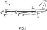
FIG. 1 illustrates an aircraft having a container for storing potable water, in accordance with various embodiments; -
FIG. 2 illustrates a system for detecting water levels in the container of the aircraft ofFIG. 1 , in accordance with various embodiments; -
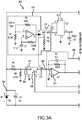
FIGS. 3A and3B illustrate a sensing controller of the system ofFIG. 2 , in accordance with various embodiments; and -
FIG. 4 is a flowchart illustrating a method for determining a fluid level of a container of an aircraft, in accordance with various embodiments. - The detailed description of exemplary embodiments herein makes reference to the accompanying drawings, which show exemplary embodiments by way of illustration. While these exemplary embodiments are described in sufficient detail to enable those skilled in the art to practice the exemplary embodiments of the disclosure, it should be understood that other embodiments may be realized and that logical changes and adaptations in design and construction may be made within the scope of the invention as defined by the claims. Thus, the detailed description herein is presented for purposes of illustration only and not limitation. The steps recited in any of the method or process descriptions may be executed in any order and are not necessarily limited to the order presented.
- Furthermore, any reference to singular includes plural embodiments, and any reference to more than one component or step may include a singular embodiment or step. Also, any reference to attached, fixed, connected or the like may include permanent, removable, temporary, partial, full and/or any other possible attachment option. Additionally, any reference to without contact (or similar phrases) may also include reduced contact or minimal contact. Surface shading lines may be used throughout the figures to denote different parts but not necessarily to denote the same or different materials.
- Referring now to
FIG. 1 , anaircraft 100 may include one ormore container 102 for retaining or storing a liquid, such as potable water. Referring now toFIG. 2 , asystem 203 for detecting a fluid level in thecontainer 102 is shown. Thesystem 203 includes thecontainer 102, acontroller 200, aconductive plate 212, and aninsulator 214. - The
container 102 may have amain body 206 formed from a carbon composite material, or any other materials being non-corrosive and having semiconductor properties. In that regard, themain body 206 may have conductive properties. Themain body 206 may have anouter surface 208 exposed to an environment of thecontainer 102 and aninner surface 210 which contacts the liquid, such as potable water. It is desirable for theinner surface 210 of themain body 206 to avoid corrosion. Thesystem 203 facilitates detection of the fluid level while reducing or eliminating the likelihood of corrosion of theinner surface 210. - The
conductive plate 212 may be separated from themain body 206 by theinsulator 214. Theinsulator 214 may include any insulator such as fiberglass, glass, a polymer, or the like. Theconductive plate 212 may include any conductive material including metals such as copper, tin, gold, silver, or the like. In various embodiments, theinsulator 214 may include a window formed integral with themain body 206, and theconductive plate 212 may be embedded within the window. In various embodiments, theinsulator 214 may be installed on theouter surface 208 of themain body 206, and theconductive plate 212 may be integrally or non-integrally installed on or embedded within theinsulator 214. - The
controller 200 may include one or more logic devices such as one or more of a central processing unit (CPU), an accelerated processing unit (APU), a digital signal processor (DSP), a field programmable gate array (FPGA), an application specific integrated circuit (ASIC), or the like. In various embodiments, thecontroller 200 may further include any non-transitory memory known in the art. The memory may store instructions usable by the logic device to perform operations. - The
controller 200 may be coupled to theconductive plate 212 via afirst lead 216 and to themain body 206 of thecontainer 102 via asecond lead 218. Thecontroller 200 may include asensing controller 202 and a determiningcontroller 204. Thesensing controller 202 may receive a direct current (DC) aircraft power signal from the determiningcontroller 204 or from another source. Thesensing controller 202 may output a first signal to theconductive plate 212 via thefirst lead 216, and may receive a second signal from theconductive plate 212 via thefirst lead 216. The first signal may include a DC power signal, and the second signal may include a DC power signal. - Because the
conductive plate 212 is separated from themain body 206 via theinsulator 214, theconductive plate 212 and themain body 206 may function as a capacitor. In that regard, thesensing controller 202 may receive, adjust, and output the second signal as anoutput signal 205. Theoutput signal 205 may correspond to a fluid level of the fluid in thecontainer 102 due to the capacitance between theconductive plate 212 and themain body 206. The amplitude of the second signal may correspond to the water level (i.e., a greater amplitude corresponds to a greater fluid level). In that regard, the determiningcontroller 204 may determine the fluid level based on theoutput signal 205. In various embodiments, the determiningcontroller 204 may be programmed with data that corresponds an amplitude of the second signal to the fluid level and, in various embodiments, the determiningcontroller 204 may learn which amplitudes corresponds to each fluid level. - In various embodiments, it may be desirable for the fluid 201 in the
container 102 to be ionized in order to facilitate the capacitance. - The
system 203 provides various benefits and advantages. No corrosive materials are in contact with the fluid 201, increasing the useful life of thesystem 203. In that regard, theinsulator 214 may be non-corrosive. Additionally, thesystem 203 may be used with a container having any shape, as the capacitance between thecontainer 102 and theconductive plate 212 will provide a reliable estimate of the remaining fluid level regardless of the shape of the container. - Referring now to
FIGS. 3A and3B , additional details of thesensing controller 202 are shown. Thesensing controller 202 may receive directcurrent aircraft power 300, which in various embodiments may be 28 volts. An inductor L1 may reduce electromagnetic interference (EMI) from theDC aircraft power 300. Diodes D2 and D3, along with a capacitor C4 and apower converter 312 may reduce the voltage of the power signal at alocation 302. For example, the voltage of the power signal at thelocation 302 may be between 1 and 20 volts, between 2 and 10 volts, or about 5 volts. Where used in this context, about refers to the referenced value plus or minus 10 percent. Two resistors R5, R6 may operate as a voltage divider to further reduce the voltage of the power signal at alocation 304, such as to between 0.1 and 5 volts, between 0.5 volts and 2 volts, or about 1 volt. - An
oscillator 310, which may include various electronic components, may create an oscillating signal. For example, the oscillating signal may be between 100 Hertz (Hz) and 1 Kilohertz (KHz), between 100 Hz and 700 Hz, or about 400 Hz. The oscillating signal may control operation of aswitch 306. - The
switch 306 may receive the oscillating signal along with the power signal from thelocation 304. Theswitch 306 may further be coupled to thefirst lead 216. In that regard, theswitch 306 may switch between a first position (as shown) in which the power at thelocation 304 is transmitted to thefirst lead 216, and a second position in which the power from thefirst lead 216 is received by the switch at alocation 307. The switching of the switch may be controlled by the oscillating signal. A capacitor C2 may hold the charge received at thelocation 307. - A collection of amplifiers 308 (including a
first amplifier 314, asecond amplifier 316, and a third amplifier 318) may receive the power signal from thelocation 307 and may adjust a gain and offset of the voltage received from thefirst lead 216. The output of theamplifiers 308 may be output as theoutput signal 205. The second lead 218 (coupled to themain body 206 ofFIG. 2 ) may be connected to anelectrical ground 328 of thesensing controller 202. A capacitor C6 may function as a filter for the input of thecontroller 202. - A
connector 322 may be installed between the sensingcontroller 202 and the inputs and outputs 300, 205, 218, 216, 320 and may facilitate replacing the sensing circuit with relative ease. - Referring now to
FIG. 4 , amethod 400 for detecting a fluid level of a fluid within a container is shown. Themethod 400 may be performed by similar components as thesystem 203 ofFIG. 2 . The method may begin inblock 402 in which a controller may output a first signal, such as a DC power signal, to a conductive plate. The conductive plate may be similar to theconductive plate 212 ofFIG. 2 . In that regard, the conductive plate may be located on a container formed using a semiconductor material, and the conductive plate may be electrically isolated from the container. - In
block 404, the controller or a different controller may receive a second signal from the conductive plate. For example, the second signal may likewise be a DC power signal. In that regard, the second signal may have an amplitude. Due to the capacitive properties between the conductive plate and the semiconductor container, the amplitude of the second signal may correspond to a fluid level of the fluid within the container. In that regard, a single conductive plate located on the container may be sufficient to determine the fluid level regardless of the fluid level and regardless of a shape of the container. This is beneficial as an aircraft manufacturer may design containers having various shapes in order to maximize space on the aircraft. - In
block 406, the controller or a different controller may determine the fluid level of the fluid within the container based on the second signal. For example and because the amplitude of the second signal may correspond to the fluid level, the controller may determine the fluid level based on the amplitude of the second signal. - Benefits and other advantages have been described herein with regard to specific embodiments. Furthermore, the connecting lines shown in the various figures contained herein are intended to represent exemplary functional relationships and/or physical couplings between the various elements. It should be noted that many alternative or additional functional relationships or physical connections may be present in a practical system. However, the benefits, advantages, and any elements that may cause any benefit or advantage to occur or become more pronounced are not to be construed as critical, required, or essential features or elements of the disclosure. The scope of the disclosure is accordingly to be limited by nothing other than the appended claims, in which reference to an element in the singular is not intended to mean "one and only one" unless explicitly so stated, but rather "one or more." Moreover, where a phrase similar to "at least one of A, B, or C" is used in the claims, it is intended that the phrase be interpreted to mean that A alone may be present in an embodiment, B alone may be present in an embodiment, C alone may be present in an embodiment, or that any combination of the elements A, B and C may be present in a single embodiment; for example, A and B, A and C, B and C, or A and B and C.
- Systems, methods and apparatus are provided herein. In the detailed description herein, references to "various embodiments", "one embodiment", "an embodiment", "an example embodiment", etc., indicate that the embodiment described may include a particular feature, structure, or characteristic, but every embodiment may not necessarily include the particular feature, structure, or characteristic. Moreover, such phrases are not necessarily referring to the same embodiment. Further, when a particular feature, structure, or characteristic is described in connection with an embodiment, it is submitted that it is within the knowledge of one skilled in the art to affect such feature, structure, or characteristic in connection with other embodiments whether or not explicitly described. After reading the description, it will be apparent to one skilled in the relevant art(s) how to implement the disclosure in alternative embodiments.
Claims (15)
- A system for detecting a fluid level in a container (102), the system comprising:the container having an inner surface (210) and an outer surface (208) and formed using a semiconductor material;a conductive plate (212) located on the outer surface of the container; andan insulator (214) located between the conductive plate and the container.
- The system of claim 1, further comprising:a lead (216) coupled to the conductive plate; anda controller (200) coupled to the lead and configured to transmit a first signal to the conductive plate via the lead and to receive a second signal from the conductive plate via the lead.
- The system of claim 2, wherein the controller includes a switch (306) having a first position to transmit the first signal to the conductive plate and a second position to receive the second signal from the conductive plate.
- The system of any preceding claim, wherein the first signal and the second signal are direct current, DC, signals.
- The system of claim 4, wherein the controller is further configured to receive a DC aircraft power signal (300) and convert the DC aircraft power signal to the first signal.
- The system of claim 2 or any claim dependent thereon, further comprising a second lead (218) coupled to the container and to a ground in the controller.
- The system of any preceding claim, wherein the insulator includes at least one of glass, fiberglass, or a polymer, and optionally wherein the insulator includes a fiberglass window in the container and the conductive plate includes a metal embedded within the fiberglass window.
- A system for detecting a fluid level in a container, the system comprising:the container (102) having an inner surface (210) and an outer surface (208) and formed using a carbon composite material;a conductive plate (212) located on the outer surface of the container;an insulator (214) located between the conductive plate and the container; anda controller (200) coupled to the conductive plate and configured to transmit a first signal to the conductive plate and to receive a second signal from the conductive plate.
- The system of any preceding claim, wherein the controller is further configured to determine a voltage of the second signal, and the voltage of the second signal corresponds to the fluid level, and optionally wherein the controller is further configured to determine the fluid level based on the voltage of the second signal.
- A method for detecting a fluid level in a container, the method comprising:outputting a first signal to a conductive plate (212), the conductive plate being located on the container (102) formed from a semiconductor material and electrically isolated from the container;receiving a second signal having an amplitude from the conductive plate; anddetermining a fluid level of a fluid in the container based on the amplitude of the second signal.
- The method of claim 10, wherein the first signal is output to the conductive plate via a first lead (216) and the second signal is received from the conductive plate using the same first lead.
- The method of claim 10 or 11, wherein the conductive plate is separated from the container via a fiberglass window, and the conductive plate includes a metal embedded within the fiberglass window.
- The method of any of claims 10 to 12, wherein the container is electrically connected to an electrical ground.
- The method of any of claims 10 to 13, further comprising controlling a switch (306) to be in a first position to cause the outputting the first signal, and then controlling the switch to be in a second position to cause the receiving the second signal.
- The method of any of claims 10 to 14, further comprising receiving a power signal and converting the power signal to the first signal; and/or wherein the first signal and the second signal are direct current, DC, signals.
Applications Claiming Priority (2)
| Application Number | Priority Date | Filing Date | Title |
|---|---|---|---|
| US202063011890P | 2020-04-17 | 2020-04-17 | |
| US17/212,841 US11796374B2 (en) | 2020-04-17 | 2021-03-25 | Composite water tank level sensor |
Publications (2)
| Publication Number | Publication Date |
|---|---|
| EP3901590A1 true EP3901590A1 (en) | 2021-10-27 |
| EP3901590B1 EP3901590B1 (en) | 2024-01-31 |
Family
ID=75539239
Family Applications (1)
| Application Number | Title | Priority Date | Filing Date |
|---|---|---|---|
| EP21168682.9A Active EP3901590B1 (en) | 2020-04-17 | 2021-04-15 | Composite water tank level sensor |
Country Status (3)
| Country | Link |
|---|---|
| US (1) | US11796374B2 (en) |
| EP (1) | EP3901590B1 (en) |
| BR (1) | BR102021007224A2 (en) |
Families Citing this family (2)
| Publication number | Priority date | Publication date | Assignee | Title |
|---|---|---|---|---|
| WO2023178512A1 (en) * | 2022-03-22 | 2023-09-28 | 深圳市大疆创新科技有限公司 | Mobile platform |
| US20230358582A1 (en) * | 2022-05-04 | 2023-11-09 | Spraying Systems Co. | Flowmeter and method |
Citations (6)
| Publication number | Priority date | Publication date | Assignee | Title |
|---|---|---|---|---|
| US5315872A (en) * | 1993-05-11 | 1994-05-31 | Edo Corporation, Fiber Science Division | Liquid level sensor for electrically conductive liquid |
| EP2626675A1 (en) * | 2012-02-13 | 2013-08-14 | Goodrich Corporation | Liquid level sensing system |
| EP2840366A1 (en) * | 2013-08-21 | 2015-02-25 | Goodrich Corporation | Liquid level sensing systems |
| US20150204709A1 (en) * | 2013-10-24 | 2015-07-23 | U.S.A. As Represented By The Administrator Of The National Aeronautics And Space Administration | Multi-Layer Wireless Sensor Construct for Use at Electrically-Conductive Material Surfaces |
| US20160202105A1 (en) * | 2015-01-13 | 2016-07-14 | Krohne Messtechnik Gmbh | Device for determining the fill level of a medium in a container |
| WO2018225010A1 (en) * | 2017-06-07 | 2018-12-13 | Critical Materials, S.A. | Fuel tank with integrated level sensors, in particular for aerial vehicles |
Family Cites Families (15)
| Publication number | Priority date | Publication date | Assignee | Title |
|---|---|---|---|---|
| US4149231A (en) * | 1977-05-04 | 1979-04-10 | Bunker Ramo Corporation | Capacitance-to-voltage transformation circuit |
| GB2094004B (en) * | 1980-08-23 | 1984-05-02 | Smiths Industries Ltd | Fluid-gauging systems |
| US5182545A (en) * | 1989-01-06 | 1993-01-26 | Standex International Corporation | Fluid level sensor having capacitive sensor |
| RU2039692C1 (en) * | 1993-06-01 | 1995-07-20 | Акционерное общество закрытого типа "СМS" | Container for transportation of chemically active liquids |
| JP3647528B2 (en) | 1995-11-14 | 2005-05-11 | 横浜ゴム株式会社 | Fiber reinforced plastic container |
| JP4208572B2 (en) | 2000-12-20 | 2009-01-14 | アバータックス・リサーチ・アンド・ディベロップメント・リミテッド | Method and apparatus for measuring levels |
| US7114391B2 (en) * | 2003-12-26 | 2006-10-03 | Ngk Spark Plug Co., Ltd. | Liquid level detection apparatus |
| KR100850657B1 (en) * | 2004-07-06 | 2008-08-07 | 미쓰비시 쇼지 가부시키가이샤 | Method for manufacturing carbon fiber reinforced carbon composite material suitable for semiconductor heat sink |
| CN101039153B (en) * | 2006-03-15 | 2011-11-16 | 大唐移动通信设备有限公司 | Device and method for detecting period signal |
| US7997132B2 (en) | 2008-06-09 | 2011-08-16 | Rochester Gauges, Inc. | Capacitive sensor assembly for determining relative position |
| US9574928B2 (en) * | 2012-02-13 | 2017-02-21 | Goodrich Corporation | Liquid level sensing systems |
| US10161779B2 (en) | 2015-05-26 | 2018-12-25 | University Of Utah Research Foundation | Liquid level sensor measuring a characteristic indicative of inductive coupling |
| US10433666B1 (en) | 2015-08-17 | 2019-10-08 | Board Of Trustees Of The University Of Alabama, For And On Behalf Of The University Of Alabama In Huntsville | Liquid container systems and methods for monitoring user hydration |
| JP6706212B2 (en) * | 2017-01-13 | 2020-06-03 | 愛三工業株式会社 | Fuel supply device |
| US10976147B2 (en) * | 2018-02-02 | 2021-04-13 | American University Of Beirut | Thickness measurement device and methods of use |
-
2021
- 2021-03-25 US US17/212,841 patent/US11796374B2/en active Active
- 2021-04-15 BR BR102021007224-5A patent/BR102021007224A2/en unknown
- 2021-04-15 EP EP21168682.9A patent/EP3901590B1/en active Active
Patent Citations (6)
| Publication number | Priority date | Publication date | Assignee | Title |
|---|---|---|---|---|
| US5315872A (en) * | 1993-05-11 | 1994-05-31 | Edo Corporation, Fiber Science Division | Liquid level sensor for electrically conductive liquid |
| EP2626675A1 (en) * | 2012-02-13 | 2013-08-14 | Goodrich Corporation | Liquid level sensing system |
| EP2840366A1 (en) * | 2013-08-21 | 2015-02-25 | Goodrich Corporation | Liquid level sensing systems |
| US20150204709A1 (en) * | 2013-10-24 | 2015-07-23 | U.S.A. As Represented By The Administrator Of The National Aeronautics And Space Administration | Multi-Layer Wireless Sensor Construct for Use at Electrically-Conductive Material Surfaces |
| US20160202105A1 (en) * | 2015-01-13 | 2016-07-14 | Krohne Messtechnik Gmbh | Device for determining the fill level of a medium in a container |
| WO2018225010A1 (en) * | 2017-06-07 | 2018-12-13 | Critical Materials, S.A. | Fuel tank with integrated level sensors, in particular for aerial vehicles |
Also Published As
| Publication number | Publication date |
|---|---|
| US11796374B2 (en) | 2023-10-24 |
| US20210325231A1 (en) | 2021-10-21 |
| BR102021007224A2 (en) | 2021-10-19 |
| EP3901590B1 (en) | 2024-01-31 |
Similar Documents
| Publication | Publication Date | Title |
|---|---|---|
| EP3901590B1 (en) | Composite water tank level sensor | |
| US10422680B2 (en) | Method for monitoring at least one media-specific property of a medium | |
| EP2626675B1 (en) | Liquid level sensing system | |
| EP2720006B1 (en) | Fuel tank monitoring system | |
| US20090212849A1 (en) | Capacitive moisture independent crush protection | |
| US10793097B2 (en) | Capacitive measurement circuit with sensor wiring diagnostics | |
| CN103797359A (en) | Apparatus for measuring the electrical conductivity of a liquid medium | |
| US20110133756A1 (en) | Apparatus for capacitively measuring changes | |
| EP1553389A1 (en) | Liquid level detection apparatus | |
| US9994173B2 (en) | Increasing the availability of ultrasound-based driver assistance systems in the event of undervoltage in the vehicle | |
| KR102227603B1 (en) | Integrated Leak Sensing System Using Ground Isolation | |
| EP3865830B1 (en) | Liquid level sensing systems | |
| EP4506231A1 (en) | Contact determination method and contact determination device | |
| US9574928B2 (en) | Liquid level sensing systems | |
| CN112292587B (en) | Fill level sensor or point level sensor with temperature compensation | |
| EP2869043B1 (en) | Hybrid connection device | |
| US10054578B2 (en) | Fuel property sensor | |
| US12092651B2 (en) | Hydrometer device | |
| US10097166B1 (en) | Transformer coupled control isolation for direct current control signals | |
| EP3901589B1 (en) | Capacitive point source level sensor for potable water systems | |
| WO2008090157A1 (en) | Liquid level resonance sensor assembly | |
| EP2569462B1 (en) | Adaptive active cathodic protection | |
| JP2007114153A (en) | Water detection device and wireless device | |
| EP3514906B1 (en) | System for and method of controlling inrush current between a power source and a load | |
| JP2018151363A (en) | Fluid detector and fluid detection device including the same |
Legal Events
| Date | Code | Title | Description |
|---|---|---|---|
| PUAI | Public reference made under article 153(3) epc to a published international application that has entered the european phase |
Free format text: ORIGINAL CODE: 0009012 |
|
| STAA | Information on the status of an ep patent application or granted ep patent |
Free format text: STATUS: THE APPLICATION HAS BEEN PUBLISHED |
|
| AK | Designated contracting states |
Kind code of ref document: A1 Designated state(s): AL AT BE BG CH CY CZ DE DK EE ES FI FR GB GR HR HU IE IS IT LI LT LU LV MC MK MT NL NO PL PT RO RS SE SI SK SM TR |
|
| B565 | Issuance of search results under rule 164(2) epc |
Effective date: 20210924 |
|
| STAA | Information on the status of an ep patent application or granted ep patent |
Free format text: STATUS: REQUEST FOR EXAMINATION WAS MADE |
|
| 17P | Request for examination filed |
Effective date: 20220427 |
|
| RBV | Designated contracting states (corrected) |
Designated state(s): AL AT BE BG CH CY CZ DE DK EE ES FI FR GB GR HR HU IE IS IT LI LT LU LV MC MK MT NL NO PL PT RO RS SE SI SK SM TR |
|
| REG | Reference to a national code |
Ref country code: DE Free format text: PREVIOUS MAIN CLASS: G01F0023260000 Ref country code: DE Ref legal event code: R079 Ref document number: 602021008842 Country of ref document: DE Free format text: PREVIOUS MAIN CLASS: G01F0023260000 Ipc: G01F0023263000 |
|
| GRAP | Despatch of communication of intention to grant a patent |
Free format text: ORIGINAL CODE: EPIDOSNIGR1 |
|
| STAA | Information on the status of an ep patent application or granted ep patent |
Free format text: STATUS: GRANT OF PATENT IS INTENDED |
|
| RIC1 | Information provided on ipc code assigned before grant |
Ipc: G01F 23/26 20060101ALI20230728BHEP Ipc: G01F 23/263 20220101AFI20230728BHEP |
|
| INTG | Intention to grant announced |
Effective date: 20230906 |
|
| RIN1 | Information on inventor provided before grant (corrected) |
Inventor name: SHEARER, JON |
|
| P01 | Opt-out of the competence of the unified patent court (upc) registered |
Effective date: 20230922 |
|
| GRAS | Grant fee paid |
Free format text: ORIGINAL CODE: EPIDOSNIGR3 |
|
| GRAA | (expected) grant |
Free format text: ORIGINAL CODE: 0009210 |
|
| STAA | Information on the status of an ep patent application or granted ep patent |
Free format text: STATUS: THE PATENT HAS BEEN GRANTED |
|
| AK | Designated contracting states |
Kind code of ref document: B1 Designated state(s): AL AT BE BG CH CY CZ DE DK EE ES FI FR GB GR HR HU IE IS IT LI LT LU LV MC MK MT NL NO PL PT RO RS SE SI SK SM TR |
|
| REG | Reference to a national code |
Ref country code: GB Ref legal event code: FG4D Ref country code: CH Ref legal event code: EP |
|
| REG | Reference to a national code |
Ref country code: DE Ref legal event code: R096 Ref document number: 602021008842 Country of ref document: DE |
|
| REG | Reference to a national code |
Ref country code: IE Ref legal event code: FG4D |
|
| REG | Reference to a national code |
Ref country code: LT Ref legal event code: MG9D |
|
| REG | Reference to a national code |
Ref country code: NL Ref legal event code: MP Effective date: 20240131 |
|
| PG25 | Lapsed in a contracting state [announced via postgrant information from national office to epo] |
Ref country code: IS Free format text: LAPSE BECAUSE OF FAILURE TO SUBMIT A TRANSLATION OF THE DESCRIPTION OR TO PAY THE FEE WITHIN THE PRESCRIBED TIME-LIMIT Effective date: 20240531 |
|
| PG25 | Lapsed in a contracting state [announced via postgrant information from national office to epo] |
Ref country code: LT Free format text: LAPSE BECAUSE OF FAILURE TO SUBMIT A TRANSLATION OF THE DESCRIPTION OR TO PAY THE FEE WITHIN THE PRESCRIBED TIME-LIMIT Effective date: 20240131 |
|
| PG25 | Lapsed in a contracting state [announced via postgrant information from national office to epo] |
Ref country code: GR Free format text: LAPSE BECAUSE OF FAILURE TO SUBMIT A TRANSLATION OF THE DESCRIPTION OR TO PAY THE FEE WITHIN THE PRESCRIBED TIME-LIMIT Effective date: 20240501 |
|
| REG | Reference to a national code |
Ref country code: AT Ref legal event code: MK05 Ref document number: 1654177 Country of ref document: AT Kind code of ref document: T Effective date: 20240131 |
|
| PG25 | Lapsed in a contracting state [announced via postgrant information from national office to epo] |
Ref country code: NL Free format text: LAPSE BECAUSE OF FAILURE TO SUBMIT A TRANSLATION OF THE DESCRIPTION OR TO PAY THE FEE WITHIN THE PRESCRIBED TIME-LIMIT Effective date: 20240131 Ref country code: HR Free format text: LAPSE BECAUSE OF FAILURE TO SUBMIT A TRANSLATION OF THE DESCRIPTION OR TO PAY THE FEE WITHIN THE PRESCRIBED TIME-LIMIT Effective date: 20240131 Ref country code: RS Free format text: LAPSE BECAUSE OF FAILURE TO SUBMIT A TRANSLATION OF THE DESCRIPTION OR TO PAY THE FEE WITHIN THE PRESCRIBED TIME-LIMIT Effective date: 20240430 |
|
| PG25 | Lapsed in a contracting state [announced via postgrant information from national office to epo] |
Ref country code: ES Free format text: LAPSE BECAUSE OF FAILURE TO SUBMIT A TRANSLATION OF THE DESCRIPTION OR TO PAY THE FEE WITHIN THE PRESCRIBED TIME-LIMIT Effective date: 20240131 |
|
| PG25 | Lapsed in a contracting state [announced via postgrant information from national office to epo] |
Ref country code: AT Free format text: LAPSE BECAUSE OF FAILURE TO SUBMIT A TRANSLATION OF THE DESCRIPTION OR TO PAY THE FEE WITHIN THE PRESCRIBED TIME-LIMIT Effective date: 20240131 |
|
| PG25 | Lapsed in a contracting state [announced via postgrant information from national office to epo] |
Ref country code: RS Free format text: LAPSE BECAUSE OF FAILURE TO SUBMIT A TRANSLATION OF THE DESCRIPTION OR TO PAY THE FEE WITHIN THE PRESCRIBED TIME-LIMIT Effective date: 20240430 Ref country code: NO Free format text: LAPSE BECAUSE OF FAILURE TO SUBMIT A TRANSLATION OF THE DESCRIPTION OR TO PAY THE FEE WITHIN THE PRESCRIBED TIME-LIMIT Effective date: 20240430 Ref country code: NL Free format text: LAPSE BECAUSE OF FAILURE TO SUBMIT A TRANSLATION OF THE DESCRIPTION OR TO PAY THE FEE WITHIN THE PRESCRIBED TIME-LIMIT Effective date: 20240131 Ref country code: LT Free format text: LAPSE BECAUSE OF FAILURE TO SUBMIT A TRANSLATION OF THE DESCRIPTION OR TO PAY THE FEE WITHIN THE PRESCRIBED TIME-LIMIT Effective date: 20240131 Ref country code: IS Free format text: LAPSE BECAUSE OF FAILURE TO SUBMIT A TRANSLATION OF THE DESCRIPTION OR TO PAY THE FEE WITHIN THE PRESCRIBED TIME-LIMIT Effective date: 20240531 Ref country code: HR Free format text: LAPSE BECAUSE OF FAILURE TO SUBMIT A TRANSLATION OF THE DESCRIPTION OR TO PAY THE FEE WITHIN THE PRESCRIBED TIME-LIMIT Effective date: 20240131 Ref country code: GR Free format text: LAPSE BECAUSE OF FAILURE TO SUBMIT A TRANSLATION OF THE DESCRIPTION OR TO PAY THE FEE WITHIN THE PRESCRIBED TIME-LIMIT Effective date: 20240501 Ref country code: FI Free format text: LAPSE BECAUSE OF FAILURE TO SUBMIT A TRANSLATION OF THE DESCRIPTION OR TO PAY THE FEE WITHIN THE PRESCRIBED TIME-LIMIT Effective date: 20240131 Ref country code: ES Free format text: LAPSE BECAUSE OF FAILURE TO SUBMIT A TRANSLATION OF THE DESCRIPTION OR TO PAY THE FEE WITHIN THE PRESCRIBED TIME-LIMIT Effective date: 20240131 Ref country code: BG Free format text: LAPSE BECAUSE OF FAILURE TO SUBMIT A TRANSLATION OF THE DESCRIPTION OR TO PAY THE FEE WITHIN THE PRESCRIBED TIME-LIMIT Effective date: 20240131 Ref country code: AT Free format text: LAPSE BECAUSE OF FAILURE TO SUBMIT A TRANSLATION OF THE DESCRIPTION OR TO PAY THE FEE WITHIN THE PRESCRIBED TIME-LIMIT Effective date: 20240131 |
|
| PG25 | Lapsed in a contracting state [announced via postgrant information from national office to epo] |
Ref country code: PT Free format text: LAPSE BECAUSE OF FAILURE TO SUBMIT A TRANSLATION OF THE DESCRIPTION OR TO PAY THE FEE WITHIN THE PRESCRIBED TIME-LIMIT Effective date: 20240531 Ref country code: PL Free format text: LAPSE BECAUSE OF FAILURE TO SUBMIT A TRANSLATION OF THE DESCRIPTION OR TO PAY THE FEE WITHIN THE PRESCRIBED TIME-LIMIT Effective date: 20240131 |
|
| PG25 | Lapsed in a contracting state [announced via postgrant information from national office to epo] |
Ref country code: SE Free format text: LAPSE BECAUSE OF FAILURE TO SUBMIT A TRANSLATION OF THE DESCRIPTION OR TO PAY THE FEE WITHIN THE PRESCRIBED TIME-LIMIT Effective date: 20240131 Ref country code: PT Free format text: LAPSE BECAUSE OF FAILURE TO SUBMIT A TRANSLATION OF THE DESCRIPTION OR TO PAY THE FEE WITHIN THE PRESCRIBED TIME-LIMIT Effective date: 20240531 Ref country code: PL Free format text: LAPSE BECAUSE OF FAILURE TO SUBMIT A TRANSLATION OF THE DESCRIPTION OR TO PAY THE FEE WITHIN THE PRESCRIBED TIME-LIMIT Effective date: 20240131 Ref country code: LV Free format text: LAPSE BECAUSE OF FAILURE TO SUBMIT A TRANSLATION OF THE DESCRIPTION OR TO PAY THE FEE WITHIN THE PRESCRIBED TIME-LIMIT Effective date: 20240131 |
|
| PG25 | Lapsed in a contracting state [announced via postgrant information from national office to epo] |
Ref country code: DK Free format text: LAPSE BECAUSE OF FAILURE TO SUBMIT A TRANSLATION OF THE DESCRIPTION OR TO PAY THE FEE WITHIN THE PRESCRIBED TIME-LIMIT Effective date: 20240131 |
|
| PG25 | Lapsed in a contracting state [announced via postgrant information from national office to epo] |
Ref country code: SM Free format text: LAPSE BECAUSE OF FAILURE TO SUBMIT A TRANSLATION OF THE DESCRIPTION OR TO PAY THE FEE WITHIN THE PRESCRIBED TIME-LIMIT Effective date: 20240131 |
|
| PG25 | Lapsed in a contracting state [announced via postgrant information from national office to epo] |
Ref country code: CZ Free format text: LAPSE BECAUSE OF FAILURE TO SUBMIT A TRANSLATION OF THE DESCRIPTION OR TO PAY THE FEE WITHIN THE PRESCRIBED TIME-LIMIT Effective date: 20240131 Ref country code: EE Free format text: LAPSE BECAUSE OF FAILURE TO SUBMIT A TRANSLATION OF THE DESCRIPTION OR TO PAY THE FEE WITHIN THE PRESCRIBED TIME-LIMIT Effective date: 20240131 |
|
| PG25 | Lapsed in a contracting state [announced via postgrant information from national office to epo] |
Ref country code: SK Free format text: LAPSE BECAUSE OF FAILURE TO SUBMIT A TRANSLATION OF THE DESCRIPTION OR TO PAY THE FEE WITHIN THE PRESCRIBED TIME-LIMIT Effective date: 20240131 |
|
| PG25 | Lapsed in a contracting state [announced via postgrant information from national office to epo] |
Ref country code: SM Free format text: LAPSE BECAUSE OF FAILURE TO SUBMIT A TRANSLATION OF THE DESCRIPTION OR TO PAY THE FEE WITHIN THE PRESCRIBED TIME-LIMIT Effective date: 20240131 Ref country code: SK Free format text: LAPSE BECAUSE OF FAILURE TO SUBMIT A TRANSLATION OF THE DESCRIPTION OR TO PAY THE FEE WITHIN THE PRESCRIBED TIME-LIMIT Effective date: 20240131 Ref country code: RO Free format text: LAPSE BECAUSE OF FAILURE TO SUBMIT A TRANSLATION OF THE DESCRIPTION OR TO PAY THE FEE WITHIN THE PRESCRIBED TIME-LIMIT Effective date: 20240131 Ref country code: EE Free format text: LAPSE BECAUSE OF FAILURE TO SUBMIT A TRANSLATION OF THE DESCRIPTION OR TO PAY THE FEE WITHIN THE PRESCRIBED TIME-LIMIT Effective date: 20240131 Ref country code: DK Free format text: LAPSE BECAUSE OF FAILURE TO SUBMIT A TRANSLATION OF THE DESCRIPTION OR TO PAY THE FEE WITHIN THE PRESCRIBED TIME-LIMIT Effective date: 20240131 Ref country code: CZ Free format text: LAPSE BECAUSE OF FAILURE TO SUBMIT A TRANSLATION OF THE DESCRIPTION OR TO PAY THE FEE WITHIN THE PRESCRIBED TIME-LIMIT Effective date: 20240131 |
|
| REG | Reference to a national code |
Ref country code: DE Ref legal event code: R097 Ref document number: 602021008842 Country of ref document: DE |
|
| PG25 | Lapsed in a contracting state [announced via postgrant information from national office to epo] |
Ref country code: MC Free format text: LAPSE BECAUSE OF FAILURE TO SUBMIT A TRANSLATION OF THE DESCRIPTION OR TO PAY THE FEE WITHIN THE PRESCRIBED TIME-LIMIT Effective date: 20240131 |
|
| PG25 | Lapsed in a contracting state [announced via postgrant information from national office to epo] |
Ref country code: MC Free format text: LAPSE BECAUSE OF FAILURE TO SUBMIT A TRANSLATION OF THE DESCRIPTION OR TO PAY THE FEE WITHIN THE PRESCRIBED TIME-LIMIT Effective date: 20240131 |
|
| REG | Reference to a national code |
Ref country code: CH Ref legal event code: PL |
|
| PG25 | Lapsed in a contracting state [announced via postgrant information from national office to epo] |
Ref country code: IT Free format text: LAPSE BECAUSE OF FAILURE TO SUBMIT A TRANSLATION OF THE DESCRIPTION OR TO PAY THE FEE WITHIN THE PRESCRIBED TIME-LIMIT Effective date: 20240131 |
|
| PLBE | No opposition filed within time limit |
Free format text: ORIGINAL CODE: 0009261 |
|
| STAA | Information on the status of an ep patent application or granted ep patent |
Free format text: STATUS: NO OPPOSITION FILED WITHIN TIME LIMIT |
|
| PG25 | Lapsed in a contracting state [announced via postgrant information from national office to epo] |
Ref country code: LU Free format text: LAPSE BECAUSE OF NON-PAYMENT OF DUE FEES Effective date: 20240415 |
|
| REG | Reference to a national code |
Ref country code: BE Ref legal event code: MM Effective date: 20240430 |
|
| PG25 | Lapsed in a contracting state [announced via postgrant information from national office to epo] |
Ref country code: LU Free format text: LAPSE BECAUSE OF NON-PAYMENT OF DUE FEES Effective date: 20240415 Ref country code: IT Free format text: LAPSE BECAUSE OF FAILURE TO SUBMIT A TRANSLATION OF THE DESCRIPTION OR TO PAY THE FEE WITHIN THE PRESCRIBED TIME-LIMIT Effective date: 20240131 |
|
| 26N | No opposition filed |
Effective date: 20241101 |
|
| PG25 | Lapsed in a contracting state [announced via postgrant information from national office to epo] |
Ref country code: BE Free format text: LAPSE BECAUSE OF NON-PAYMENT OF DUE FEES Effective date: 20240430 |
|
| PG25 | Lapsed in a contracting state [announced via postgrant information from national office to epo] |
Ref country code: BE Free format text: LAPSE BECAUSE OF NON-PAYMENT OF DUE FEES Effective date: 20240430 Ref country code: CH Free format text: LAPSE BECAUSE OF NON-PAYMENT OF DUE FEES Effective date: 20240430 |
|
| PG25 | Lapsed in a contracting state [announced via postgrant information from national office to epo] |
Ref country code: IE Free format text: LAPSE BECAUSE OF NON-PAYMENT OF DUE FEES Effective date: 20240415 |
|
| PG25 | Lapsed in a contracting state [announced via postgrant information from national office to epo] |
Ref country code: SI Free format text: LAPSE BECAUSE OF FAILURE TO SUBMIT A TRANSLATION OF THE DESCRIPTION OR TO PAY THE FEE WITHIN THE PRESCRIBED TIME-LIMIT Effective date: 20240131 |
|
| PGFP | Annual fee paid to national office [announced via postgrant information from national office to epo] |
Ref country code: DE Payment date: 20250319 Year of fee payment: 5 |
|
| PG25 | Lapsed in a contracting state [announced via postgrant information from national office to epo] |
Ref country code: CY Free format text: LAPSE BECAUSE OF FAILURE TO SUBMIT A TRANSLATION OF THE DESCRIPTION OR TO PAY THE FEE WITHIN THE PRESCRIBED TIME-LIMIT; INVALID AB INITIO Effective date: 20210415 |
|
| PG25 | Lapsed in a contracting state [announced via postgrant information from national office to epo] |
Ref country code: HU Free format text: LAPSE BECAUSE OF FAILURE TO SUBMIT A TRANSLATION OF THE DESCRIPTION OR TO PAY THE FEE WITHIN THE PRESCRIBED TIME-LIMIT; INVALID AB INITIO Effective date: 20210415 |
|
| PGFP | Annual fee paid to national office [announced via postgrant information from national office to epo] |
Ref country code: GB Payment date: 20260319 Year of fee payment: 6 |
|
| PGFP | Annual fee paid to national office [announced via postgrant information from national office to epo] |
Ref country code: FR Payment date: 20260319 Year of fee payment: 6 |