EP3901582A1 - Induktive winkelmesseinrichtung - Google Patents
Induktive winkelmesseinrichtung Download PDFInfo
- Publication number
- EP3901582A1 EP3901582A1 EP21153915.0A EP21153915A EP3901582A1 EP 3901582 A1 EP3901582 A1 EP 3901582A1 EP 21153915 A EP21153915 A EP 21153915A EP 3901582 A1 EP3901582 A1 EP 3901582A1
- Authority
- EP
- European Patent Office
- Prior art keywords
- conductor track
- track section
- conductor
- section
- distance
- Prior art date
- Legal status (The legal status is an assumption and is not a legal conclusion. Google has not performed a legal analysis and makes no representation as to the accuracy of the status listed.)
- Granted
Links
Images

Classifications
-
- G—PHYSICS
- G01—MEASURING; TESTING
- G01D—MEASURING NOT SPECIALLY ADAPTED FOR A SPECIFIC VARIABLE; ARRANGEMENTS FOR MEASURING TWO OR MORE VARIABLES NOT COVERED IN A SINGLE OTHER SUBCLASS; TARIFF METERING APPARATUS; MEASURING OR TESTING NOT OTHERWISE PROVIDED FOR
- G01D5/00—Mechanical means for transferring the output of a sensing member; Means for converting the output of a sensing member to another variable where the form or nature of the sensing member does not constrain the means for converting; Transducers not specially adapted for a specific variable
- G01D5/12—Mechanical means for transferring the output of a sensing member; Means for converting the output of a sensing member to another variable where the form or nature of the sensing member does not constrain the means for converting; Transducers not specially adapted for a specific variable using electric or magnetic means
- G01D5/14—Mechanical means for transferring the output of a sensing member; Means for converting the output of a sensing member to another variable where the form or nature of the sensing member does not constrain the means for converting; Transducers not specially adapted for a specific variable using electric or magnetic means influencing the magnitude of a current or voltage
- G01D5/20—Mechanical means for transferring the output of a sensing member; Means for converting the output of a sensing member to another variable where the form or nature of the sensing member does not constrain the means for converting; Transducers not specially adapted for a specific variable using electric or magnetic means influencing the magnitude of a current or voltage by varying inductance, e.g. by a movable armature
- G01D5/204—Mechanical means for transferring the output of a sensing member; Means for converting the output of a sensing member to another variable where the form or nature of the sensing member does not constrain the means for converting; Transducers not specially adapted for a specific variable using electric or magnetic means influencing the magnitude of a current or voltage by varying inductance, e.g. by a movable armature by influencing the mutual induction between two or more coils
- G01D5/2053—Mechanical means for transferring the output of a sensing member; Means for converting the output of a sensing member to another variable where the form or nature of the sensing member does not constrain the means for converting; Transducers not specially adapted for a specific variable using electric or magnetic means influencing the magnitude of a current or voltage by varying inductance, e.g. by a movable armature by influencing the mutual induction between two or more coils by a movable non-ferromagnetic conductive element
- G01D5/206—Mechanical means for transferring the output of a sensing member; Means for converting the output of a sensing member to another variable where the form or nature of the sensing member does not constrain the means for converting; Transducers not specially adapted for a specific variable using electric or magnetic means influencing the magnitude of a current or voltage by varying inductance, e.g. by a movable armature by influencing the mutual induction between two or more coils by a movable non-ferromagnetic conductive element constituting a short-circuiting element
Definitions
- the invention relates to an inductive angle measuring device for determining relative angular positions according to claim 1.
- Inductive angle measuring devices are used, for example, as angle measuring devices for determining the angular position of two machine parts that can be rotated relative to one another.
- excitation tracks and receiver tracks for example in the form of conductor tracks, are often applied to a common, usually multilayer, printed circuit board that is firmly connected, for example, to a stator of an angle measuring device.
- this circuit board is a scale element on which graduation structures are applied and which is connected to the rotor of the angle encoder in a rotationally fixed manner. If an electrical excitation current that changes over time is applied to the excitation coils, signals that are dependent on the angular position are generated in the receiver coils during the relative rotation between the rotor and the stator. These signals are then processed further in evaluation electronics.
- Such inductive angle measuring devices are often used as measuring devices for electrical drives to determine the relative movement or the relative position of corresponding machine parts.
- the angular position values generated are used by subsequent electronics Control of the drives is supplied via a corresponding interface arrangement.
- an inductive angle sensor which has a short-circuit line on the rotor element which can be scanned by receiving coils which have comparatively long straight sections.
- the invention is based on the object of creating an inductive angle measuring device by means of which a precise determination of a relative angular position is made possible by filtering out harmonics from signals received from receiver conductor tracks.
- the inductive angle measuring device has a scanning element and a scale element.
- the scale element comprises a graduation track running around an axis, the graduation track having several conductor track groups which are electrically connected and are arranged in a row in the measuring direction so that adjacent conductor track groups have a center-to-center spacing in the measuring direction.
- the conductor track groups each have a first conductor track section, a second conductor track section, a third conductor track section and a fourth conductor track section. These four conductor track sections extend transversely to the measuring direction, that is to say with a directional component orthogonal to the direction of measurement.
- the direction of measurement often corresponds to the circumferential direction in relation to the axis or around the axis.
- the first conductor track section and the second conductor track section are electrically connected to one another.
- the third conductor track section and the fourth conductor track section are also electrically connected to one another.
- the first conductor track section is arranged offset with respect to the third conductor track section at a distance in the measuring direction.
- the fourth conductor track section is arranged offset with respect to the second conductor track section at the (same) distance.
- the distance is dimensioned in such a way that it corresponds to the center-to-center distance divided by a natural number M greater than or equal to 4.
- the scanning element has an excitation track and a receiver track with at least two receiver conductor tracks, the receiver conductor tracks having a sinusoidal circumferential, spatially periodic course with a period length which corresponds to the center-to-center distance.
- signals can be generated by the receiver conductor tracks which have practically no disruptive harmonic components, the sinusoidal receiver conductor tracks not having any straight sections.
- the scanning element and the scale element are usually arranged opposite one another and are spaced apart from one another by an air gap which extends in the axial or radial direction.
- the receiver conductor tracks are often arranged in such a way that they have a phase offset (e.g. a phase offset of 90 °) to one another.
- the inductive angle measuring device is advantageously configured in such a way that the scanning element has two excitation tracks which each comprise at least one conductor track, the excitation tracks running in the measuring direction or along the measuring direction.
- the receiver track is arranged between the excitation tracks.
- the angle measuring device also includes an electronic circuit through which in the excitation tracks an electrical excitation current can be generated. At a specific point in time, the excitation current advantageously runs in the same direction in the at least two excitation tracks.
- the natural number M is greater than or equal to 6.
- center-to-center distances and distances between conductor track sections are specified in terms of angles, i.e. either in degrees or fractions of a full angle or in radians.
- a conductor track group is to be understood in particular as an area on the scale element in which congruent courses of the conductor track sections, in particular of the entire conductor tracks, are present over a section in the measuring direction with an extent that corresponds to the center-to-center distance TP, if the section in question is around the angular center-to-center distance TP or an integral multiple thereof is rotated.
- the scale element thus has sections, namely the conductor track groups, which are arranged in a periodically recurring manner with the period which corresponds to the center-to-center distance TP.
- the conductor track groups are electrically connected to one another in series, so that an electrically closed dividing track is present; in particular, the conductor track groups can be partial areas of conductor tracks which are in particular designed to be endless.
- the conductor track groups can be designed in such a way that the course of the conductor track sections located therein is axially symmetrical with respect to a radially extending axis of symmetry.
- the scale element is advantageously designed in such a way that the four conductor track sections each extend in a direction with a radial directional component in relation to the axis.
- the distance, based on the measurement direction, between two not directly adjacent conductor track sections within a conductor track group corresponds to half the center-to-center distance.
- the first conductor track section is arranged offset in the measuring direction with respect to the fourth conductor track section at a distance that corresponds to half the center-to-center distance.
- the third conductor track section is arranged offset with respect to the second conductor track section at a distance which corresponds to half the center-to-center distance.
- the first conductor track section and the second conductor track section as well as a first connection conductor track section and a second connection conductor track section are advantageously sections of a first conductor track. Furthermore, the first conductor track section and the second conductor track section are electrically connected to one another in series by the first connection conductor track section and the second connection conductor track section.
- the third conductor track section and the fourth conductor track section as well as a third connection conductor track section and a fourth connection conductor track section are sections of a second conductor track, the third conductor track section and the fourth conductor track section being electrically connected to one another in series by the third connection conductor track section and the fourth connection conductor track section.
- the connecting conductor track sections advantageously extend in one direction with a directional component parallel to the measuring direction.
- the four conductor track sections are advantageously arranged on a flat plane.
- the connecting conductor track sections are arranged alternately radially on the inside and radially on the outside in the measuring direction with respect to the conductor track sections.
- the conductor track sections can also be arranged on a circumferential surface, for example a jacket surface of a cylindrical body.
- the four conductor track sections extend in one direction with an axial directional component (based on the (rotational) axis).
- the scale element has a curved surface on which the graduation track is arranged.
- the conductor track groups can then be designed in such a way that the course of the conductor track sections located therein is axially symmetrical with respect to an axis of symmetry running parallel to the (rotational) axis.
- the four conductor track sections have a width in the measuring direction of less than 300 ⁇ m, in particular of less than 200 ⁇ m or of less than 150 ⁇ m.
- the conductor track groups each have, in addition to the four conductor track sections, a fifth conductor track section, a sixth conductor track section, a seventh conductor track section and an eighth conductor track section.
- the fifth conductor track section and the sixth conductor track section are electrically connected to one another.
- the seventh conductor track section and the eighth conductor track section are also electrically connected to one another.
- the first conductor track section is offset from the fifth conductor track section at a distance in the measuring direction and the third conductor track section is offset from the seventh conductor track section at a distance in the measuring direction.
- the respective distance corresponds to the center-to-center distance divided by a natural number M greater than or equal to 6.
- the distance between the first conductor track section and the fifth conductor track section is advantageously the same as the distance between the third conductor track section and the seventh conductor track section.
- the at least two receiver conductor tracks are arranged on a flat plane, in particular the plane of the at least two receiver conductor tracks being arranged axially offset to the plane of the four conductor track sections.
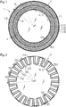
- the invention is described on the basis of an angle measuring device which is used to detect an angular position ⁇ between a scanning element 1 ( Figure 1 ) and a scale element 2 ( Figure 2 ) or a scale is determined, the axis A in the figures being oriented orthogonally to the respective plane of the drawing.
- the circumferential direction can thus be defined as a measuring direction U.
- the scanning element 1 is designed as a printed circuit board, which has several layers, and is used for scanning the scale element 2.
- the in the Figure 1 The scanning element 1 shown has four receiver conductor tracks 1.11, 1.12, 1.13, 1.14, which are arranged in a receiver track 1.1, as well as exciter tracks 1.3, 1.4.
- the receiver conductor tracks 1.11, 1.12, 1.13, 1.14 are arranged radially between the excitation tracks 1.3, 1.4.
- the receiver conductor tracks 1.11, 1.12, 1.13, 1.14 run on different levels with plated-through holes, so that undesired short circuits are avoided at crossing points.
- at least two layers are provided in the circuit board structure.
- the receiver conductor tracks 1.11, 1.12, 1.13, 1.14 have a spatially periodic course that is essentially sinusoidal or sinusoidal.
- the abscissa x (indicated by the arrow) runs on the receiver conductor tracks 1.11, 1.12, 1.13, 1.14 Figure 1 ) of the associated sine lines along a circular line around the axis A.
- each of the receiver conductor tracks 1.11, 1.12, 1.13, 1.14 runs through sixteen full sine periods (16 ⁇ 2 ⁇ or 16 ⁇ 360 °) or the circumferential abscissa x has a length of 16 * 2 ⁇ or 16 * 360 ° or 16 * PL.
- the receiver conductor tracks 1.11, 1.12, 1.13, 1.14 are offset relative to one another along the measurement direction U.
- adjacent receiver conductor tracks 1.11, 1.12, 1.13, 1.14 are offset from one another by 1/8 of the full sine period (by ⁇ / 4 or 45 ° with respect to the abscissa x).
- the receiver conductor tracks 1.11, 1.12, 1.13, 1.14 are electrically connected in such a way that they can ultimately deliver signals that are phase-shifted by 90 °.
- the receiver conductor tracks 1.11, 1.12, 1.13, 1.14 each have sixteen periods along the circular line, so that each of the receiver conductor tracks 1.11, 1.12, 1.13, 1.14 has a period length PL of 22.5 °.
- length sizes in the circumferential or measuring direction U are indicated by angular dimensions.
- the scale element 2 is shown in a top view.
- the scale element 2 consists of a substrate which, in the exemplary embodiment shown, is made of epoxy resin and on which a first conductor track 2.1 and a second conductor track 2.2 are arranged in a graduation track TS1.
- copper was applied to the substrate as the material for the first conductor track 2.1 and the second conductor track 2.2.
- the conductor track 2.1 and the second conductor track 2.2 each have a width of 150 ⁇ m.
- the graduation track TS1 is arranged centrally with respect to the axis A and circumferentially around the axis A in the measuring direction U.
- the first conductor track 2.1 and the second conductor track 2.2 have a meandering course and are endless.
- the division track TS1 can (or the associated first conductor track 2.1 and second conductor track 2.2 can) be subdivided into what are known as conductor track groups TG.
- the graduation track TS1 comprises a total of sixteen conductor track groups TG, the center-to-center spacing TP of which is 22.5 ° (360 ° / 16) or 0.39 (2 ⁇ / 16) radians.
- Conductor track groups TG are sections on the graduation track TS1 which extend over an angular distance corresponding to the center-to-center distance TP. In adjacent conductor track groups TG, the courses of the first conductor track 2.1 and the second conductor track 2.2 are congruent when one of the Conductor groups TG is rotated about the axis A with an amount corresponding to the center-to-center distance TP.
- a conductor track group TG extends in the circumferential direction between the radial lines R, the distance between which is also 22.5 ° (2 ⁇ TP / 2).
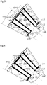
- such conductor track groups TG have a first conductor track section 2.11, a second conductor track section 2.12, a third conductor track section 2.21 and a fourth conductor track section 2.22, the four conductor track sections 2.11, 2.12; 2.21, 2.22 extend transversely to the measuring direction U, that is, in relation to the axis A in the radial direction and each have a width of 150 ⁇ m.
- the conductor track sections 2.11, 2.12; 2.21, 2.22 shown slightly conical with respect to their width with decreasing width towards the axis A.
- the width of 150 ⁇ m relates to the maximum width of the conductor track sections 2.11, 2.12; 2.21, 2.22.
- the four conductor track sections 2.11, 2.12; 2.21, 2.22 can be assigned to two pairs of conductor track sections P1112, P2122.
- the first conductor track 2.1 thus has two radial conductor track sections 2.11, 2.12, namely the first conductor track section 2.11 and the second conductor track section 2.12, which are assigned to the conductor track section pair P1112.
- the second conductor track 2.2 has two radial conductor track sections 2.21, 2.22 (here the third conductor track section 2.21 and the fourth conductor track section 2.22), which are assigned to the conductor track section pair P2122. Furthermore, the first conductor track 2.1 and the second conductor track 2.2 have connecting conductor track sections 2.13, 2.14, 2.23, 2.24 which, in the exemplary embodiment presented, run in the circumferential or measuring direction U and electrically connect the radial conductor track sections 2.21, 2.22 within a pair of conductor track sections P1112, P2122.
- the first conductor track 2.1 comprises a first connection conductor track section 2.13 and a second connection conductor track section 2.14, so that the first conductor track section 2.11 and the second conductor track section 2.12 are electrically connected to one another in series by the first and second connection conductor track sections 2.13, 2.14.
- the second conductor track also includes 2.2 a third connecting conductor track section 2.23 and a fourth connecting conductor track section 2.24.
- the third interconnect section 2.21 and the fourth interconnect section 2.22 are electrically connected to one another in series through the third connecting interconnect section 2.23 and the fourth interconnecting interconnect section 2.24.
- the graduation track TS1 thus consists of a periodic sequence of electrically conductive conductor track sections 2.11, 2.12; 2.21, 2.22 between which non-conductive dividing areas are arranged.
- the conductor track sections 2.11, 2.12; 2.21, 2.22, which belong to one and the same conductor track 2.1, 2.2, are electrically connected to one another in series.
- Those radial conductor track sections 2.11, 2.12; 2.21, 2.22, which belong to different pairs of conductor track sections P1112, P2122, are each arranged offset in the circumferential direction at a distance d12. Accordingly, the two immediately adjacent two radial conductor track sections 2.11, 2.12 of the first conductor track 2.1 are arranged offset at a distance d12 in the circumferential direction from the two radial conductor track sections 2.21, 2.22 of the second conductor track 2.2.
- the first conductor track section 2.11 with respect to the third conductor track section 2.21 and the fourth conductor track section 2.22 with respect to the second conductor track section 2.12 are each offset by a distance d12 in the measuring direction U.
- the first conductor track section 2.11 of the first conductor track 2.1 is offset by a distance d1122 in the measuring direction U from the fourth conductor track section 2.22, which is not arranged directly adjacent to the first conductor track section 2.11 and belongs to the second conductor track 2.2.
- the conductor track sections 2.11, 2.12; 2.21, 2.22 arranged axially symmetrically with respect to the central, radially extending axis of symmetry.
- the connecting conductor track sections 2.13, 2.14, 2.23, 2.24 are likewise arranged axially symmetrically between the radial lines R.
- the scanning element 1 and the scale element 2 face each other axially, so that the axis A runs through the center points of both elements and in the case of a relative rotation between the scale element 2 and the scanning element 1 in the receiver conductor tracks 1.11, 1.12, 1.13, 1.14 a from the respective angular position dependent signal can be generated by induction effects.
- the prerequisite for the formation of corresponding signals is that the excitation tracks 1.3, 1.4 generate a time-changing electromagnetic excitation field in the area of the scanned graduation track TS1.
- the excitation tracks 1.3, 1.4 are designed as a plurality of planar-parallel, current-carrying individual conductor tracks.
- the scanning element 1 has an electronic circuit which comprises, for example, an ASIC module.
- This electronic circuit of the scanning element 1 works not only as an evaluation element, but also as an excitation control element, under whose control the excitation current, which then flows through the excitation tracks 1.3, 1.4 or through the individual conductor tracks, is generated. Both excitation tracks 1.3, 1.4 are thus energized by one and the same excitation control element.
- an excitation current flows through all of the excitation tracks 1.3, 1.4 in the same direction, then around the respective excitation track 1.3, 1.4 an electromagnetic tube-like or cylindrical shape is formed Field off.
- the field lines of the resulting electromagnetic field run in the form of concentric circles around the excitation tracks 1.3, 1.4, the direction of the field lines depending in a known manner on the direction of the current in the excitation tracks 1.3, 1.4.
- the current direction I13, I14 ( Figure 1 ) of the excitation tracks 1.3, 1.4 or the corresponding interconnection of the excitation tracks 1.3, 1.4 is to be selected in the same direction, so that the field lines in the area of the receiver track 1.1 are oriented in opposite directions.
- the current flow in the excitation tracks 1.3, 1.4 induces a current in the first conductor track 2.1 and in the second conductor track 2.2 of the scale element 2, the induced currents each having a current direction I21, I22 ( Figure 2 ) exhibit.
- the current direction I21 in the first conductor track 2.1 and the current direction I22 in the second conductor track 2.2 of the scale element 2 run parallel to one another (not in opposite directions or anti-parallel).
- the considerations in connection with the current directions I13, I14; I21, I22 only apply to one and the same point in time, since the excitation current is an alternating current.
- the first conductor track 2.1 and the second conductor track 2.2 run in a meander shape and nested in one another.
- the dimensioning of the distances d12, d1122, d2112 between the relevant conductor track sections 2.11, 2.12; 2.21, 2.22 in connection with the sinusoidal course of the receiver conductor tracks 1.11, 1.12, 1.13, 1.14 has the consequence that in the exemplary embodiment presented, the signals generated by the receiver conductor tracks 1.11, 1.12, 1.13, 1.14 have almost no third harmonics (harmonics) and practically no even-numbered ones Exhibit harmonics. This minimizes interpolation errors for determining the angular position values.
- FIG. 4 Another embodiment (second embodiment) of the invention is described. This differs from the first exemplary embodiment essentially in that instead of the connecting conductor track sections 2.13, 2.14, 2.23, 2.24 ( Figure 3 ) now one-piece connecting conductor track sections 2.23 ', 2.24' are provided, each with a parallel course, through which the entire induced current can flow.
- the graduation track TS1 can also comprise a third conductor track 2.3 and a fourth conductor track 2.4.
- the conductor track groups TG here additionally each have a fifth conductor track section 2.31, a sixth conductor track section 2.32, a seventh conductor track section 2.41 and an eighth conductor track section 2.42.
- the first conductor track section 2.11 is arranged offset with respect to the fifth conductor track section 2.31 at a distance d13 in the measurement direction U.
- the third conductor track section 2.21 is offset from the seventh conductor track section 2.41 at a distance d24 in the measuring direction U.
- conductor track sections 2.31, 2.32; 2.41, 2.42 can be assigned to two pairs of conductor track sections P3132, P4142.
- the third conductor track 2.3 has two radial conductor track sections 2.31, 2.32, which are assigned to the pair of conductor track sections P3132
- the fourth conductor track 2.4 has two radial conductor track sections 2.41, 2.42, which are assigned to the pair of conductor track sections P4142.
- the third conductor track 2.3 and the fourth conductor track 2.4 also have connecting conductor track sections 2.33, 2.34, 2.43, 2.44 which, in the exemplary embodiment presented, run in the circumferential direction and the radial conductor track sections 2.31, 2.32; 2.41, 2.42 electrically connect to one another within a pair of conductor track sections P3132, P4142.
- the graduation track TS1 consists of a periodic sequence of electrically conductive conductor track sections 2.11, 2.12; 2.21, 2.22; 2.31, 2.32; 2.41, 2.42 between which non-conductive dividing areas are arranged.
- d 12th TP / 6th
- two conductor track sections 2.11, 2.12; 2.21, 2.22; 2.31, 2.32; 2.41, 2.42 of a conductor track group TG each have a distance which corresponds to half the center-to-center distance TP.
- the fifth conductor track section 2.31 of the third conductor track 2.3 is offset by a distance TP / 2 in the measuring direction U from the fourth conductor track section 2.22, which is not arranged directly adjacent to the third conductor track section 2.31 and belongs to the second conductor track 2.2.
- All conductor tracks 2.1 to 2.4 run in a meander shape and are nested in one another.
- the third harmonic filtered from the signals generated by the receiver conductor tracks 1.11, 1.12, 1.13, 1.14, but also the fifth harmonic and all even-numbered harmonics.
- FIG. 6 an alternative embodiment of the scanning element 1 (fourth embodiment) is shown. Similar to the first exemplary embodiment, two conductor tracks 2.1, 2.2 are provided there, the first conductor track 2.1 and the second conductor track 2.2 not being designed as conductors that are electrically separated from one another, that is to say are not arranged electrically purely in parallel, but are connected in series.
- connecting conductor tracks 2.5, 2.6 are arranged on two levels or with the aid of a second copper layer of the printed circuit board of the scanning element 1.
- These connect the two conductor tracks 2.1, 2.2 with the help of micro vias in such a way that they are connected to one another in series.
- This arrangement has the particular advantage that it is prevented that different currents can flow in the conductor tracks 2.1, 2.2. Such an effect (currents of different sizes) could lead to limited harmonic filtering or filtering of the harmonics.
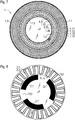
- a fifth embodiment is shown in Figures 7 and 8 shown.
- the scanning element 1 now also includes a further inner receiver track 1.2, which includes four receiver conductor tracks 1.21, 1.22, 1.23, 1.24.
- the receiver conductor tracks 1.21, 1.22, 1.23, 1.24 have a spatially periodic course that is essentially sinusoidal or sinusoidal, the abscissa of the sinus lines running along a circular line around the axis A.
- the receiver conductor tracks 1.21, 1.22, 1.23, 1.24 are arranged analogously to the first exemplary embodiment, that is to say offset by 45 ° relative to one another, so that they can deliver signals that are phase-shifted by 90 ° with appropriate electrical interconnection.
- the receiver conductor tracks 1.21, 1.22, 1.23, 1.24 of the inner receiver track 1.2 each have three periods along the circular line.
- the sensing element 1 comprises a further excitation track 1.5, which comprises a plurality of excitation lines or excitation conductor tracks.
- the current direction of the excitation track is 1.5 based on the current direction of the excitation tracks 1.3, 1.4 to be selected in opposite directions.
- the inner graduation track TS2 consists of graduation areas 2.7 in which electrically conductive material, here copper, is applied. No conductive material is arranged between the dividing areas 2.7.
- the receiver track 1.1 can be used to generate comparatively high-resolution angular position values for the relative angular position, while the further receiver track 1.2 can be used to generate comparatively coarse angular position values.
- the fine angular position values are connected to the comparatively coarse angular position values, so that the circuit generates a high-resolution absolute angular position value as a result.
Landscapes
- Physics & Mathematics (AREA)
- General Physics & Mathematics (AREA)
- Transmission And Conversion Of Sensor Element Output (AREA)
Abstract
Description
- Die Erfindung betrifft eine induktive Winkelmesseinrichtung zur Bestimmung von Relativwinkelpositionen gemäß dem Anspruch 1.
- Induktive Winkelmesseinrichtungen werden beispielsweise als Winkelmessgeräte zur Bestimmung der Winkelposition zweier relativ zueinander drehbarer Maschinenteile verwendet. Bei induktiven Winkelmesseinrichtungen sind häufig Erregerspuren und Empfängerspuren etwa in Form von Leiterbahnen auf einer gemeinsamen meist mehrlagigen Leiterplatte aufgebracht, die beispielsweise mit einem Stator eines Winkelmessgeräts fest verbunden ist. Dieser Leiterplatte gegenüber befindet sich ein Skalenelement, auf dem Teilungsstrukturen aufgebracht sind, und welches mit dem Rotor des Winkelmessgeräts drehfest verbunden ist. Wenn an den Erregerspulen ein zeitlich wechselnder elektrischer Erregerstrom angelegt wird, werden in den Empfängerspulen während der Relativdrehung zwischen Rotor und Stator von der Winkelposition abhängige Signale erzeugt. Diese Signale werden dann in einer Auswerteelektronik weiterverarbeitet.
- Häufig werden derartige induktive Winkelmesseinrichtungen als Messgeräte für elektrische Antriebe, zur Bestimmung der Relativbewegung beziehungsweise der Relativlage von entsprechenden Maschinenteilen eingesetzt. In diesem Fall werden die erzeugten Winkelpositionswerte einer Folgeelektronik zur Ansteuerung der Antriebe über eine entsprechende Schnittstellenanordnung zugeführt.
- In der
EP 2 329 225 B1 der Anmelderin wird eine induktive Winkelmesseinrichtung beschrieben, bei der durch die Bildung eines Mittelwerts ein vergleichsweise exaktes Messergebnis erreicht wird, das reduzierte Oberschwingungen beziehungsweise Oberwellen, insbesondere der dritten Ordnung aufweist. - Aus der
EP 0 909 955 A2 ist ein induktiver Winkelsensor bekannt, der eine Kurzschlussleitung am Rotorelement aufweist, welche durch Empfangsspulen abtastbar ist, die vergleichsweise lange geradlinig verlaufende Abschnitte aufweisen. - Der Erfindung liegt die Aufgabe zugrunde eine induktive Winkelmesseinrichtung zu schaffen, durch die eine genaue Bestimmung einer relativen Winkelposition ermöglicht ist durch Herausfiltern von Oberwellen aus von Empfängerleiterbahnen empfangenen Signalen.
- Diese Aufgabe wird erfindungsgemäß durch die Merkmale des Anspruches 1 gelöst.
- Die induktive Winkelmesseinrichtung weist ein Abtastelement und ein Skalenelement auf. Das Skalenelement umfasst eine um eine Achse umlaufende Teilungsspur, wobei die Teilungsspur mehrere Leiterbahngruppen aufweist, welche elektrisch verbunden sind und in Messrichtung so aneinandergereiht angeordnet sind, dass benachbarte Leiterbahngruppen in Messrichtung einen Mittenabstand aufweisen. Die Leiterbahngruppen weisen jeweils einen ersten Leiterbahnabschnitt, einen zweiten Leiterbahnabschnitt, einen dritten Leiterbahnabschnitt und einen vierten Leiterbahnabschnitt auf. Diese vier Leiterbahnabschnitte erstrecken sich quer zur Messrichtung, also mit einer Richtungskomponente orthogonal zur Messrichtung. Häufig entspricht die Messrichtung der Umfangsrichtung bezogen auf die Achse beziehungsweise um die Achse herum. Der erste Leiterbahnabschnitt und der zweite Leiterbahnabschnitt sind elektrisch miteinander verbunden. Ebenso sind der dritte Leiterbahnabschnitt und der vierte Leiterbahnabschnitt elektrisch miteinander verbunden. Innerhalb einer Leiterbahngruppe ist der erste Leiterbahnabschnitt gegenüber dem dritten Leiterbahnabschnitt mit einem Abstand in Messrichtung versetzt angeordnet. Zudem ist innerhalb einer Leiterbahngruppe der vierte Leiterbahnabschnitt gegenüber dem zweiten Leiterbahnabschnitt mit dem (gleichen) Abstand versetzt angeordnet. Der Abstand ist so dimensioniert, dass er dem Mittenabstand geteilt durch eine Natürliche Zahl M grösser oder gleich 4 entspricht. Das Abtastelement weist eine Erregerspur und eine Empfängerspur mit zumindest zwei Empfängerleiterbahnen auf, wobei die Empfängerleiterbahnen einen sinusförmigen umlaufenden räumlich periodischen Verlauf aufweisen mit einer Periodenlänge, die dem Mittenabstand entspricht.
- Mit Hilfe dieser Vorrichtung sind durch die Empfängerleiterbahnen Signale erzeugbar, die praktisch keine störenden Oberwellenanteile aufweisen, wobei die sinusförmigen Empfängerleiterbahnen keine geradlinigen Abschnitte aufweisen.
- Üblicherweise sind das Abtastelement und das Skalenelement einander gegenüber liegend angeordnet und durch einen Luftspalt, der sich in axialer oder radialer Richtung erstreckt, voneinander beabstandet. Häufig sind die Empfängerleiterbahnen so angeordnet, dass diese einen Phasenversatz (z.B. einen Phasenversatz von 90°) zueinander aufweisen.
- Mit Vorteil ist die induktive Winkelmesseinrichtung so konfiguriert, dass das Abtastelement zwei Erregerspuren aufweist, welche jeweils mindestens eine Leiterbahn umfassen, wobei die Erregerspuren in Messrichtung beziehungsweise entlang der Messrichtung verlaufen. Zudem ist die Empfängerspur zwischen den Erregerspuren angeordnet. Die Winkelmesseinrichtung umfasst weiterhin eine elektronische Schaltung, durch welche in den Erregerspuren ein elektrischer Erregerstrom erzeugbar ist. Mit Vorteil verläuft zu einem bestimmten Zeitpunkt der Erregerstrom in den zumindest zwei Erregerspuren in gleicher Richtung.
- In weiterer Ausgestaltung der Erfindung ist die Natürliche Zahl M grösser oder gleich 6.
- Im Folgenden werden Mittenabstände und Abstände zwischen Leiterbahnabschnitten winkelmäßig angegeben also entweder in Grad beziehungsweise Bruchteilen eines Vollwinkels oder im Bogenmaß.
- Eine Leiterbahngruppe ist im Folgenden insbesondere als ein Bereich auf dem Skalenelement zu verstehen, in dem über einen Abschnitt in Messrichtung mit einer Ausdehnung, die dem Mittenabstand TP entspricht, deckungsgleiche Verläufe der Leiterbahnabschnitte, insbesondere der gesamten Leiterbahnen, vorliegen, wenn der betreffende Abschnitt um den winkelmäßigen Mittenabstand TP oder ein ganzzahliges Vielfaches davon gedreht wird. Somit weist das Skalenelement Abschnitte auf, nämlich die Leiterbahngruppen, die periodisch wiederkehrend mit der Periode, die dem Mittenabstand TP entspricht, angeordnet sind. Die Leiterbahngruppen sind elektrisch in Serie miteinander verbunden, so dass eine elektrisch geschlossene Teilungsspur vorliegt, insbesondere können die Leiterbahngruppen Teilbereiche von Leiterbahnen sein, die insbesondere endlos ausgestaltet sind.
- Die Leiterbahngruppen können so ausgestaltet sein, dass der Verlauf der darin befindlichen Leiterbahnabschnitte achsensymmetrisch bezüglich einer radial verlaufenden Symmetrieachse ist.
- Mit Vorteil ist das Skalenelement so ausgestaltet, dass sich die vier Leiterbahnabschnitte bezogen auf die Achse jeweils in einer Richtung mit radialer Richtungskomponente erstrecken.
- Vorteilhaft weist die Teilungsspur eine Anzahl N von Leiterbahngruppen auf, wobei der Mittenabstand TP dem Quotienten aus dem Vollwinkel und der Anzahl N von Leiterbahngruppen entspricht, so dass also gilt TP = 360°/N. Gleichbedeutend kann diese Betrachtung auch im Bogenmaß durchgeführt werden, so dass dann TP = 2π/N gilt.
- Gemäß einer vorteilhaften Ausgestaltung der Erfindung entspricht der Abstand, bezogen auf die Messrichtung, zwischen zwei nicht unmittelbar benachbarten Leiterbahnabschnitten innerhalb einer Leiterbahngruppe dem halben Mittenabstand. Insbesondere ist innerhalb einer Leiterbahngruppe der erste Leiterbahnabschnitt gegenüber dem vierten Leiterbahnabschnitt mit einem Abstand, der dem halben Mittenabstand entspricht, in Messrichtung versetzt angeordnet. Zudem ist innerhalb einer Leiterbahngruppe der dritte Leiterbahnabschnitt gegenüber dem zweiten Leiterbahnabschnitt mit einem Abstand, der dem halben Mittenabstand entspricht, versetzt angeordnet.
- Mit Vorteil sind der erste Leiterbahnabschnitt und der zweite Leiterbahnabschnitt sowie ein erster Verbindungsleiterbahnabschnitt und ein zweiter Verbindungsleiterbahnabschnitt Abschnitte einer ersten Leiterbahn. Weiterhin sind der erste Leiterbahnabschnitt und der zweite Leiterbahnabschnitt durch den ersten Verbindungsleiterbahnabschnitt und den zweiten Verbindungsleiterbahnabschnitt seriell elektrisch miteinander verbunden. Der dritte Leiterbahnabschnitt und der vierte Leiterbahnabschnitt sowie ein dritter Verbindungsleiterbahnabschnitt und ein vierter Verbindungsleiterbahnabschnitt sind Abschnitte einer zweiten Leiterbahn, wobei der dritte Leiterbahnabschnitt und der vierte Leiterbahnabschnitt durch den dritten Verbindungsleiterbahnabschnitt und den vierten Verbindungsleiterbahnabschnitt seriell elektrisch miteinander verbunden sind.
- Vorteilhafterweise erstrecken sich die Verbindungsleiterbahnabschnitte in einer Richtung mit einer Richtungskomponente parallel zur Messrichtung.
- Mit Vorteil sind die vier Leiterbahnabschnitte auf einer planen Ebene angeordnet.
- In weiterer Ausgestaltung der Erfindung sind die Verbindungsleiterbahnabschnitte in Messrichtung bezüglich der Leiterbahnabschnitte abwechselnd radial innen und radial außen angeordnet.
- Alternativ können die Leiterbahnabschnitte auch auf einer umlaufenden Fläche beispielsweise einer Mantelfläche eines zylindrischen Körpers angeordnet sein. In diesem Fall erstrecken sich die vier Leiterbahnabschnitte in einer Richtung mit axialer Richtungskomponente (bezogen auf die (Dreh-) Achse). Dann weist das Skalenelement eine gekrümmte Fläche auf, auf der die Teilungsspur angeordnet ist. Die Leiterbahngruppen können dann so ausgestaltet sein, dass der Verlauf der darin befindlichen Leiterbahnabschnitte achsensymmetrisch bezüglich einer parallel zur (Dreh-) Achse verlaufenden Symmetrieachse ist.
- Gemäß einer weiteren Ausgestaltung der Erfindung weisen die vier Leiterbahnabschnitte in Messrichtung eine Breite von weniger als 300 µm auf, insbesondere von weniger als 200 µm oder von weniger als 150 µm.
- In weiterer Ausgestaltung der Erfindung weisen die Leiterbahngruppen zusätzlich zu den vier Leiterbahnabschnitten jeweils einen fünften Leiterbahnabschnitt, einen sechsten Leiterbahnabschnitt, einen siebten Leiterbahnabschnitt und einen achten Leiterbahnabschnitt auf. Der fünfte Leiterbahnabschnitt und der sechste Leiterbahnabschnitt sind elektrisch miteinander verbunden. Ebenso sind der siebte Leiterbahnabschnitt und der achte Leiterbahnabschnitt elektrisch miteinander verbunden. Innerhalb einer Leiterbahngruppe ist der erste Leiterbahnabschnitt gegenüber dem fünften Leiterbahnabschnitt mit einem Abstand in Messrichtung versetzt angeordnet und der dritte Leiterbahnabschnitt gegenüber dem siebten Leiterbahnabschnitt mit einem Abstand in Messrichtung versetzt angeordnet. Dabei entspricht der jeweilige Abstand dem Mittenabstand geteilt durch eine Natürliche Zahl M grösser oder gleich 6.
- Mit Vorteil ist der Abstand zwischen dem ersten Leiterbahnabschnitt und dem fünften Leiterbahnabschnitt gleich groß wie der Abstand zwischen dem dritten Leiterbahnabschnitt und dem siebten Leiterbahnabschnitt.
- Insbesondere, wenn die vier Leiterbahnabschnitte auf einer planen Ebene angeordnet sind ist es vorteilhaft, dass die zumindest zwei Empfängerleiterbahnen auf einer planen Ebene angeordnet sind, wobei insbesondere die Ebene der zumindest zwei Empfängerleiterbahnen axial versetzt zur Ebene der vier Leiterbahnabschnitte angeordnet ist.
- Vorteilhafte Ausbildungen der Erfindung entnimmt man den abhängigen Ansprüchen.
- Weitere Einzelheiten und Vorteile der erfindungsgemäßen induktiven Winkelmesseinrichtung ergeben sich aus der nachfolgenden Beschreibung mehrerer Ausführungsbeispiele anhand der beiliegenden Figuren.
-
- Figur 1
- eine Draufsicht auf ein Abtastelement gemäß einem ersten Ausführungsbeispiel,
- Figur 2
- eine Draufsicht auf ein Skalenelement gemäß dem ersten Ausführungsbeispiel,
- Figur 3
- eine Detailansicht auf das Skalenelement gemäß dem ersten Ausführungsbeispiel,
- Figur 4
- eine Detailansicht auf das Skalenelement gemäß einem zweiten Ausführungsbeispiel,
- Figur 5
- eine Detailansicht auf das Skalenelement gemäß einem dritten Ausführungsbeispiel,
- Figur 6
- eine Detailansicht auf das Skalenelement gemäß einem vierten Ausführungsbeispiel,
- Figur 7
- eine Draufsicht auf ein Abtastelement gemäß einem fünften Ausführungsbeispiel,
- Figur 8
- eine Draufsicht auf ein Skalenelement gemäß dem fünften Ausführungsbeispiel.
- Die Erfindung wird anhand einer Winkelmesseinrichtung beschrieben, welche zur Erfassung einer Winkelposition ϕ zwischen einem Abtastelement 1 (
Figur 1 ) und einem relativ um eine Achse A drehbaren Skalenelement 2 (Figur 2 ) beziehungsweise einer Skala bestimmt ist, wobei die Achse A in den Figuren orthogonal zur jeweiligen Zeichenebene orientiert ist. Somit kann als eine Messrichtung U die Umfangsrichtung definiert werden. - Das Abtastelement 1 ist als eine Leiterplatte, welche mehrere Lagen aufweist, ausgeführt und dient zur Abtastung des Skalenelements 2. Das in der
Figur 1 gezeigte Abtastelement 1 weist vier Empfängerleiterbahnen 1.11, 1.12, 1.13, 1.14, die in einer Empfängerspur 1.1 angeordnet sind, sowie Erregerspuren 1.3, 1.4 auf. Insbesondere sind die Empfängerleiterbahnen 1.11, 1.12, 1.13, 1.14 radial zwischen den Erregerspuren 1.3, 1.4 angeordnet. Zudem verlaufen die Empfängerleiterbahnen 1.11, 1.12, 1.13, 1.14 auf unterschiedlichen Ebenen mit Durchkontaktierungen, so dass an Kreuzungspunkten unerwünschte Kurzschlüsse vermieden werden. Im gezeigten Ausführungsbeispiel sind zumindest zwei Lagen in dem Leiterplattenaufbau vorgesehen. Die Empfängerleiterbahnen 1.11, 1.12, 1.13, 1.14 weisen einen räumlich periodischen Verlauf auf, der im Wesentlichen sinusförmig beziehungsweise sinusartig ausgestaltet ist. Dabei verläuft die Abszisse x (angedeutet durch den Pfeil auf den Empfängerleiterbahnen 1.11, 1.12, 1.13, 1.14Figur 1 ) der zugehörigen Sinus-Linien entlang einer Kreislinie um die Achse A. Im vorgestellten Ausführungsbeispiel durchläuft jede der Empfängerleiterbahnen 1.11, 1.12, 1.13, 1.14 sechzehn volle Sinusperioden (16·2π oder 16·360°) beziehungsweise hat die umlaufende Abszisse x ein Länge von 16·2π oder 16·360° beziehungsweise 16·PL. Die Empfängerleiterbahnen 1.11, 1.12, 1.13, 1.14 sind relativ zueinander entlang der Messrichtung U versetzt. Im vorgestellten Ausführungsbeispiel sind benachbarte Empfängerleiterbahnen 1.11, 1.12, 1.13, 1.14 um 1/8 der vollen Sinusperiode (um π/4 oder 45° bezogen auf die Abszisse x) zueinander versetzt angeordnet. Die Empfängerleiterbahnen 1.11, 1.12, 1.13, 1.14 sind elektrisch so verschaltet, dass diese letztlich um 90° phasenversetzte Signale liefern können. Im vorgestellten Ausführungsbeispiel weisen die Empfängerleiterbahnen 1.11, 1.12, 1.13, 1.14 entlang der Kreislinie jeweils sechzehn Perioden auf, so dass jede der Empfängerleiterbahnen 1.11, 1.12, 1.13, 1.14 eine Periodenlänge PL von 22,5° aufweist. Im Folgenden werden Längengrößen in Umfangs- beziehungsweise Messrichtung U durch Winkelmaße angegeben. - In der
Figur 2 ist das Skalenelement 2 in einer Draufsicht gezeigt. Das Skalenelement 2 besteht aus einem Substrat, welches im dargestellten Ausführungsbeispiel aus Epoxydharz hergestellt ist und auf dem in einer Teilungsspur TS1 eine erste Leiterbahn 2.1 und eine zweite Leiterbahn 2.2 angeordnet sind. Als Material für die erste Leiterbahn 2.1 und die zweite Leiterbahn 2.2 wurde im gezeigten Beispiel Kupfer auf das Substrat aufgebracht. Die Leiterbahn 2.1 und die zweite Leiterbahn 2.2 weisen jeweils eine Breite von 150 µm auf. - Die Teilungsspur TS1 ist bezüglich der Achse A zentrisch und um die Achse A in Messrichtung U umlaufend angeordnet. Die erste Leiterbahn 2.1 und die zweite Leiterbahn 2.2 weisen einen mäanderförmigen Verlauf auf und sind endlos.
- Die Teilungsspur TS1 kann (beziehungsweise die zugehörige erste Leiterbahn 2.1 und zweite Leiterbahn 2.2 können) in so genannte Leiterbahngruppen TG unterteilt werden. Im vorgestellten Ausführungsbeispiel umfasst die Teilungsspur TS1 insgesamt sechzehn Leiterbahngruppen TG, deren Mittenabstand TP 22,5° (360°/16) beträgt beziehungsweise im Bogenmaß 0,39 (2π/16). Somit entspricht im vorgestellten Ausführungsbeispiel der Mittenabstand TP auf dem Skalenelement 2 der Periodenlänge PL auf dem Abtastelement 1:

- Leiterbahngruppen TG sind Abschnitte auf der Teilungsspur TS1, die sich über einen winkelmäßigen Abstand, der dem Mittenabstand TP entspricht, erstrecken. In benachbarten Leiterbahngruppen TG sind die Verläufe der ersten Leiterbahn 2.1 und der zweiten Leiterbahn 2.2 deckungsgleich, wenn eine der Leiterbahngruppen TG um die Achse A mit einem Betrag entsprechend dem Mittenabstand TP gedreht wird.
- In der
Figur 3 ist eine Leiterbahngruppe TG im Detail gezeigt. Eine Leiterbahngruppe TG erstreckt sich in Umfangsrichtung zwischen den radialen Linien R, deren Abstand ebenfalls 22,5° (2·TP/2) beträgt. Derartige Leiterbahngruppen TG weisen im vorgestellten Ausführungsbeispiel einen ersten Leiterbahnabschnitt 2.11, einen zweiten Leiterbahnabschnitt 2.12, einen dritten Leiterbahnabschnitt 2.21 und einen vierten Leiterbahnabschnitt 2.22 auf, wobei sich die vier Leiterbahnabschnitte 2.11, 2.12; 2.21, 2.22 quer zur Messrichtung U, also bezogen auf die Achse A in radialer Richtung erstrecken und jeweils eine Breite von 150 µm aufweisen. In derFigur 3 sind die Leiterbahnabschnitte 2.11, 2.12; 2.21, 2.22 bezüglich ihrer Breite leicht konisch mit abnehmender Breite zur Achse A hin dargestellt. Bei dieser Konfiguration bezieht sich die Breite von 150 µm auf die maximale Breite der Leiterbahnabschnitte 2.11, 2.12; 2.21, 2.22. Die vier Leiterbahnabschnitte 2.11, 2.12; 2.21, 2.22 können zwei Leiterbahnabschnittspaaren P1112, P2122 zugeordnet werden. Somit weist die erste Leiterbahn 2.1 zwei radiale Leiterbahnabschnitte 2.11, 2.12 auf, nämlich den ersten Leiterbahnabschnitt 2.11 und den zweiten Leiterbahnabschnitt 2.12, die dem Leiterbahnabschnittspaar P1112 zugeordnet sind. Die zweite Leiterbahn 2.2 weist zwei radiale Leiterbahnabschnitte 2.21, 2.22 auf (hier der dritte Leiterbahnabschnitt 2.21 und der vierte Leiterbahnabschnitt 2.22), die dem Leiterbahnabschnittspaar P2122 zugeordnet sind. Weiterhin weisen die erste Leiterbahn 2.1 und die zweite Leiterbahn 2.2 Verbindungsleiterbahnabschnitte 2.13, 2.14, 2.23, 2.24 auf, die im vorgestellten Ausführungsbeispiel in Umfangs- beziehungsweise in Messrichtung U verlaufen und die radialen Leiterbahnabschnitte 2.21, 2.22 innerhalb eines Leiterbahnabschnittspaares P1112, P2122 elektrisch miteinander verbinden. Insbesondere umfasst die erste Leiterbahn 2.1 einen ersten Verbindungsleiterbahnabschnitt 2.13 und einen zweiten Verbindungsleiterbahnabschnitt 2.14, so dass der erste Leiterbahnabschnitt 2.11 und der zweite Leiterbahnabschnitt 2.12 durch den ersten und zweiten Verbindungsleiterbahnabschnitt 2.13, 2.14 seriell elektrisch miteinander verbunden sind. Ebenso umfasst die zweite Leiterbahn 2.2 einen dritten Verbindungsleiterbahnabschnitt 2.23 und einen vierten Verbindungsleiterbahnabschnitt 2.24. Durch den dritten Verbindungsleiterbahnabschnitt 2.23 und den vierten Verbindungsleiterbahnabschnitt 2.24 sind der dritte Leiterbahnabschnitt 2.21 und der vierte Leiterbahnabschnitt 2.22 seriell elektrisch miteinander verbunden. - Die Teilungsspur TS1 besteht also aus einer periodischen Abfolge elektrisch leitfähiger Leiterbahnabschnitte 2.11, 2.12; 2.21, 2.22 zwischen welchen nichtleitfähige Teilungsbereiche angeordnet sind. Die Leiterbahnabschnitte 2.11, 2.12; 2.21, 2.22, die zu ein und derselben Leiterbahn 2.1, 2.2 gehören, sind in Reihe geschaltet miteinander elektrisch verbunden.
- Diejenigen radialen Leiterbahnabschnitte 2.11, 2.12; 2.21, 2.22, welche zu unterschiedlichen Leiterbahnabschnittspaaren P1112, P2122 gehören, sind jeweils mit einem Abstand d12 in Umfangsrichtung versetzt angeordnet. Demnach sind also jeweils die unmittelbar benachbarten zwei radialen Leiterbahnabschnitte 2.11, 2.12 der ersten Leiterbahn 2.1 mit einem Abstand d12 in Umfangsrichtung zu den zwei radialen Leiterbahnabschnitten 2.21, 2.22 der zweiten Leiterbahn 2.2 versetzt angeordnet. Innerhalb einer Leiterbahngruppe TG sind also der erste Leiterbahnabschnitt 2.11 gegenüber dem dritten Leiterbahnabschnitt 2.21 und der vierte Leiterbahnabschnitt 2.22 gegenüber dem zweiten Leiterbahnabschnitt 2.12 jeweils mit einem Abstand d12 in Messrichtung U versetzt angeordnet. Der Abstand d12 beträgt im vorgestellten Ausführungsbeispiel 1/6 TP. Somit gilt, dass der Abstand d12 dem Mittenabstand TP geteilt durch eine Natürliche Zahl M, hier M = 6, entspricht:

- Der erste Leiterbahnabschnitt 2.11 der ersten Leiterbahn 2.1 ist gegenüber dem vierten Leiterbahnabschnitt 2.22, der nicht unmittelbar benachbart zum ersten Leiterbahnabschnitt 2.11 angeordnet ist und zur zweiten Leiterbahn 2.2 gehört, mit einem Abstand d1122 in Messrichtung U versetzt angeordnet. Ebenso ist der zweite Leiterbahnabschnitt 2.21 der zweiten Leiterbahn 2.2 gegenüber dem dritten Leiterbahnabschnitt 2.13, der nicht unmittelbar benachbart zum zweiten Leiterbahnabschnitt 2.21 angeordnet ist und zur ersten Leiterbahn 2.1 gehört, mit einem Abstand d2112 in Messrichtung U versetzt angeordnet. Dabei gilt, dass sowohl der Abstand d1122 als auch der Abstand d2112 dem halben Mittenabstand TP entspricht:

- Zwischen den radialen Linien R sind die Leiterbahnabschnitte 2.11, 2.12; 2.21, 2.22 achsensymmetrisch bezüglich der mittigen radial verlaufenden Symmetrieachse angeordnet. Ebenso sind die Verbindungsleiterbahnabschnitte 2.13, 2.14, 2.23, 2.24 achsensymmetrisch zwischen den radialen Linien R angeordnet.
- Im zusammengebauten Zustand stehen sich das Abtastelement 1 und das Skalenelement 2 axial gegenüber, so dass die Achse A durch die Mittelpunkte beider Elemente verläuft und bei einer Relativdrehung zwischen dem Skalenelement 2 und dem Abtastelement 1 in den Empfängerleiterbahnen 1.11, 1.12, 1.13, 1.14 ein von der jeweiligen Winkelposition abhängiges Signal durch Induktionseffekte erzeugbar ist. Voraussetzung für die Bildung von entsprechenden Signalen ist, dass die Erregerspuren 1.3, 1.4 ein zeitlich wechselndes elektromagnetisches Erregerfeld im Bereich der abgetasteten Teilungsspur TS1 erzeugen. Im dargestellten Ausführungsbeispiel sind die Erregerspuren 1.3, 1.4 als mehrere planar-parallele stromdurchflossene Einzel-Leiterbahnen ausgebildet. Das Abtastelement 1 weist eine elektronische Schaltung, die beispielsweise einen ASIC-Baustein umfasst, auf. Diese elektronische Schaltung des Abtastelements 1 arbeitet nicht nur als Auswerteelement, sondern auch als Erregerkontrollelement, unter dessen Kontrolle der Erregerstrom, welcher dann durch die Erregerspuren 1.3, 1.4 beziehungsweise durch die Einzel-Leiterbahnen fließt, erzeugt wird. Somit werden beide Erregerspuren 1.3, 1.4 durch ein und dasselbe Erregerkontrollelement bestromt.
- Werden die Erregerspuren 1.3, 1.4 allesamt in der gleichen Richtung von einem Erregerstrom durchflossen, so bildet sich um die jeweilige Erregerspur 1.3, 1.4 ein schlauch- bzw. zylinderförmig orientiertes elektromagnetisches Feld aus. Die Feldlinien des resultierenden elektromagnetischen Feldes verlaufen in Form konzentrischer Kreise um die Erregerspuren 1.3, 1.4, wobei die Richtung der Feldlinien in bekannter Art und Weise von der Stromrichtung in den Erregerspuren 1.3, 1.4 abhängt. Die Stromrichtung I13, I14 (
Figur 1 ) der Erregerspuren 1.3, 1.4 beziehungsweise die entsprechende Verschaltung der Erregerspuren 1.3, 1.4 ist dabei gleichsinnig zu wählen, so dass die Feldlinien im Bereich der Empfängerspur 1.1 gegenläufig orientiert sind. Durch den Stromfluss in den Erregerspuren 1.3, 1.4 wird in der ersten Leiterbahn 2.1 und in der zweiten Leiterbahn 2.2 des Skalenelementes 2 jeweils ein Strom induziert, wobei die induzierten Ströme jeweils eine Stromrichtung I21, I22 (Figur 2 ) aufweisen. Die Stromrichtung I21 in der ersten Leiterbahn 2.1 und die Stromrichtung I22 in der zweiten Leiterbahn 2.2 des Skalenelementes 2 verlaufen parallel zueinander (nicht gegensinnig beziehungsweise antiparallel). Die Betrachtungen im Zusammenhang mit den Stromrichtungen I13, I14; I21, I22 gelten nur für ein und denselben Zeitpunkt, da der Erregerstrom ein Wechselstrom ist. - Die erste Leiterbahn 2.1 und die zweite Leiterbahn 2.2 verlaufen mäanderförmig und ineinander geschachtelt. Insbesondere die Dimensionierung der Abstände d12, d1122, d2112 zwischen den betreffenden Leiterbahnabschnitten 2.11, 2.12; 2.21, 2.22 hat in Verbindung mit dem sinusförmigen Verlauf der Empfängerleiterbahnen 1.11, 1.12, 1.13, 1.14 zur Folge, dass im vorgestellten Ausführungsbeispiel die von den Empfängerleiterbahnen 1.11, 1.12, 1.13, 1.14 erzeugten Signale nahezu keine dritte Harmonische (Oberwelle) sowie praktisch keine geradzahligen Harmonischen aufweisen. Dadurch werden für die Bestimmung der Winkelpositionswerte Interpolationsfehler minimiert.
- Anhand der
Figur 4 wird eine weitere Ausführungsform (zweites Ausführungsbeispiel) der Erfindung beschrieben. Diese unterscheidet sich vom ersten Ausführungsbeispiel im Wesentlichen dadurch, dass statt den Verbindungsleiterbahnabschnitten 2.13, 2.14, 2.23, 2.24 (Figur 3 ) mit jeweils parallelem Verlauf nunmehr einteilige Verbindungsleiterbahnabschnitte 2.23', 2.24' vorgesehen sind, durch die der gesamte induzierte Strom fließen kann. Gemäß einem dritten Ausführungsbeispiel nachFigur 5 kann die Teilungsspur TS1 neben der ersten Leiterbahn 2.1 und der zweiten Leiterbahn 2.2 auch eine dritte Leiterbahn 2.3 und eine vierte Leiterbahn 2.4 umfassen. Dementsprechend liegen in diesem Ausführungsbeispiel acht Leiterbahnabschnitte 2.11, 2.12; 2.21, 2.22; 2.31, 2.32; 2.41, 2.42 vor, die sich quer zur Messrichtung U, beziehungsweise bezogen auf die Achse A in radialer Richtung erstrecken. Demnach weisen hier die Leiterbahngruppen TG zusätzlich jeweils einen fünften Leiterbahnabschnitt 2.31, einen sechsten Leiterbahnabschnitt 2.32, einen siebten Leiterbahnabschnitt 2.41 und einen achten Leiterbahnabschnitt 2.42 auf. - Dabei ist innerhalb einer Leiterbahngruppe TG der erste Leiterbahnabschnitt 2.11 gegenüber dem fünften Leiterbahnabschnitt 2.31 mit einem Abstand d13 in Messrichtung U versetzt angeordnet. Zudem ist der dritte Leiterbahnabschnitt 2.21 gegenüber dem siebten Leiterbahnabschnitt 2.41 mit einem Abstand d24 in Messrichtung U versetzt angeordnet.
- Auch die gegenüber dem ersten Ausführungsbeispiel gemäß der
Figur 3 hinzugenommen Leiterbahnabschnitte 2.31, 2.32; 2.41, 2.42 können zwei Leiterbahnabschnittspaaren P3132, P4142 zugeordnet werden. Somit weist die dritte Leiterbahn 2.3 zwei radiale Leiterbahnabschnitte 2.31, 2.32 auf, die dem Leiterbahnabschnittspaar P3132 zugeordnet sind und die vierte Leiterbahn 2.4 weist zwei radiale Leiterbahnabschnitte 2.41, 2.42 auf, die dem Leiterbahnabschnittspaar P4142 zugeordnet sind. Weiterhin weisen auch die dritte Leiterbahn 2.3 und die vierte Leiterbahn 2.4 Verbindungsleiterbahnabschnitte 2.33, 2.34, 2.43, 2.44 auf, die im vorgestellten Ausführungsbeispiel in Umfangsrichtung verlaufen und die radialen Leiterbahnabschnitte 2.31, 2.32; 2.41, 2.42 innerhalb eines Leiterbahnabschnittspaares P3132, P4142 elektrisch miteinander verbinden. Die Teilungsspur TS1 besteht also auch in diesem Ausführungsbeispiel aus einer periodischen Abfolge elektrisch leitfähiger Leiterbahnabschnitte 2.11, 2.12; 2.21, 2.22; 2.31, 2.32; 2.41, 2.42 zwischen welchen nichtleitfähige Teilungsbereiche angeordnet sind. Der Abstand d12 zwischen den Leiterbahnabschnitten 2.11, 2.21 beziehungsweise zwischen den Leiterbahnabschnitten 2.12, 2.22 der ersten Leiterbahn 2.1 und der zweiten Leiterbahn 2.2 beträgt auch in diesem Ausführungsbeispiel 1/6 TP (Natürliche Zahl M = 6). Somit gilt:
- Weiterhin beträgt der Abstand d13 zwischen den Leiterbahnabschnitten 2.11, 2.31 beziehungsweise zwischen den Leiterbahnabschnitten 2.12, 2.32 der ersten Leiterbahn 2.1 beziehungsweise der dritten Leiterbahn 2.3 1/10 TP (Natürliche Zahl M = 10), so dass gilt:

- Außerdem gilt, dass d24 = d13, also

- Zudem weisen auch im dritten Ausführungsbeispiel zwei nicht unmittelbar benachbarte Leiterbahnabschnitte 2.11, 2.12; 2.21, 2.22; 2.31, 2.32; 2.41, 2.42 einer Leiterbahngruppe TG jeweils einen Abstand auf, der dem halben Mittenabstand TP entspricht.
- Der fünfte Leiterbahnabschnitt 2.31 der dritten Leiterbahn 2.3 ist gegenüber dem vierten Leiterbahnabschnitt 2.22, der nicht unmittelbar benachbart zum dritten Leiterbahnabschnitt 2.31 angeordnet ist und zur zweiten Leiterbahn 2.2 gehört, mit einem Abstand TP/2 in Messrichtung U versetzt angeordnet. Gleiches gilt beispielsweise auch für den zweiten Leiterbahnabschnitt 2.12 und den siebten Leiterbahnabschnitt 2.41 (Abstand TP/2).
- Sämtliche Leiterbahnen 2.1 bis 2.4 verlaufen mäanderförmig und sind ineinander geschachtelt. Im vorgestellten Ausführungsbeispiel wird nicht nur die dritte Harmonische aus den von den Empfängerleiterbahnen 1.11, 1.12, 1.13, 1.14 erzeugten Signalen gefiltert, sondern auch die fünfte Harmonische sowie alle geradzahligen Harmonischen.
- In der
Figur 6 ist eine alternative Ausgestaltung des Abtastelements 1 (viertes Ausführungsbeispiel) dargestellt. Dort sind ähnlich wie im ersten Ausführungsbeispiel zwei Leiterbahnen 2.1, 2.2 vorgesehen, wobei nun die erste Leiterbahn 2.1 und die zweite Leiterbahn 2.2 nicht als elektrisch voneinander getrennte Leiter ausgestaltet sind, also nicht elektrisch rein parallel angeordnet, sondern in Serie verschaltet sind. Zu diesem Zweck sind auf zwei Ebenen beziehungsweise mit Hilfe einer zweiten Kupferlage der Leiterplatte des Abtastelements 1 Verbindungsleiterbahnen 2.5, 2.6 angeordnet. Diese verbinden die beiden Leiterbahnen 2.1, 2.2 mit Hilfe von Micro-Vias so, dass diese seriell miteinander verbunden sind. Diese Anordnung hat insbesondere den Vorteil, dass verhindert wird, dass in den Leiterbahnen 2.1, 2.2 unterschiedliche Ströme fließen können. Ein derartiger Effekt (unterschiedlich große Ströme) könnte zu einer eingeschränkten Oberwellenfilterung beziehungsweise Filterung der Harmonischen führen. - Ein fünftes Ausführungsbeispiel ist in den
Figuren 7 und 8 gezeigt. Gemäß derFigur 7 umfasst nun das Abtastelement 1 zusätzlich noch eine weitere innere Empfängerspur 1.2, welche vier Empfängerleiterbahnen 1.21, 1.22, 1.23, 1.24 umfasst. Die Empfängerleiterbahnen 1.21, 1.22, 1.23, 1.24 weisen einen räumlich periodischen Verlauf auf, der im Wesentlichen sinusförmig beziehungsweise sinusartig ausgestaltet ist, wobei die Abszisse der Sinus-Linien entlang einer Kreislinie um die Achse A verläuft. Die Empfängerleiterbahnen 1.21, 1.22, 1.23, 1.24 sind analog zum ersten Ausführungsbeispiel angeordnet, also relativ zueinander um 45° versetzt, so dass diese bei entsprechender elektrischer Verschaltung um 90° phasenversetzte Signale liefern können. Die Empfängerleiterbahnen 1.21, 1.22, 1.23, 1.24 der inneren Empfängerspur 1.2 weisen entlang der Kreislinie jeweils drei Perioden auf. - Außerdem umfasst das Abtastelement 1 gemäß dem fünften Ausführungsbeispiel eine weitere Erregerspur 1.5, die mehrere Erregerleitungen beziehungsweise Erregerleiterbahnen umfasst. Die Stromrichtung der Erregerspur 1.5 ist bezogen auf die Stromrichtung der Erregerspuren 1.3, 1.4 gegensinnig zu wählen.
- Wie in der
Figur 8 dargestellt umfasst das Skalenelement 1 gemäß dem fünften Ausführungsbeispiel eine weitere innere Teilungsspur TS2. Die innere Teilungsspur TS2 besteht in der dargestellten Ausführungsform aus Teilungsbereichen 2.7, in denen elektrisch leitfähiges Material, hier Kupfer aufgebracht ist. Zwischen den Teilungsbereichen 2.7 ist kein leitfähiges Material angeordnet. - Durch die Empfängerspur 1.1 sind vergleichsweise hoch aufgelöste Winkelpositionswerte für die relative Winkelposition erzeugbar, während durch die weitere Empfängerspur 1.2 vergleichsweise grobe Winkelpositionswerte erzeugbar sind. In einer elektronischen Schaltung wird der Anschluss der feinen Winkelpositionswerte mit den vergleichsweise groben Winkelpositionswerten vorgenommen, so dass im Ergebnis ein hochauflösender absoluter Winkelpositionswert von der Schaltung erzeugt wird.
Claims (12)
- Induktive Winkelmesseinrichtung, die ein Abtastelement (1) und ein Skalenelement (2) aufweist, wobei- das Skalenelement (2) eine um eine Achse (A) umlaufende Teilungsspur (TS1) umfasst, wobei die Teilungsspur (TS1) mehrere Leiterbahngruppen (TG) aufweist, welche elektrisch verbunden sind und in Messrichtung (U) so aneinandergereiht angeordnet sind, dass benachbarte Leiterbahngruppen (TG) in Messrichtung (U) einen Mittenabstand (TP) aufweisen, wobei die Leiterbahngruppen (TG) jeweils einen
ersten Leiterbahnabschnitt (2.11), einen zweiten Leiterbahnabschnitt (2.12), einen dritten Leiterbahnabschnitt (2.21) und einen vierten Leiterbahnabschnitt (2.22) aufweisen, wobei sich diese Leiterbahnabschnitte (2.11, 2.12; 2.21, 2.22) quer zur Messrichtung (U) erstrecken, wobei
der erste Leiterbahnabschnitt (2.11) und der zweite Leiterbahnabschnitt (2.12) elektrisch miteinander verbunden sind, und d
er dritte Leiterbahnabschnitt (2.21) und der vierte Leiterbahnabschnitt (2.22) elektrisch miteinander verbunden sind, wobei innerhalb einer Leiterbahngruppe (TG)
der erste Leiterbahnabschnitt (2.11) gegenüber dem dritten Leiterbahnabschnitt (2.21) und
der vierte Leiterbahnabschnitt (2.22) gegenüber dem zweiten Leiterbahnabschnitt (2.12) jeweils mit einem Abstand (d12) in Messrichtung (U) versetzt angeordnet sind, wobei der Abstand (d12) dem Mittenabstand (TP) geteilt durch eine Natürliche Zahl (M) grösser oder gleich 4 entspricht,- das Abtastelement (1) eine Erregerspur (1.3, 1.4) und eine Empfängerspur (1.1) mit zumindest zwei Empfängerleiterbahnen (1.11, 1.12, 1.13, 1.14) aufweist, wobei die Empfängerleiterbahnen (1.11, 1.12, 1.13, 1.14) einen sinusförmigen Verlauf aufweisen mit einer Periodenlänge (PL), die dem Mittenabstand (TP) entspricht. - Induktive Winkelmesseinrichtung gemäß dem Anspruch 1, wobei die Winkelmesseinrichtung so konfiguriert ist, dass das Abtastelement (1) zumindest zwei Erregerspuren (1.3, 1.4) aufweist, welche jeweils mindestens eine Leiterbahn umfassen, wobei die Erregerspuren (1.3, 1.4) in Messrichtung (U) verlaufen und die Empfängerspur (1.1) zwischen den Erregerspuren (1.3, 1.4) angeordnet ist, wobei di
e Winkelmesseinrichtung weiterhin eine elektronische Schaltung umfasst, durch welche in den Erregerspuren (1.3, 1.4) ein elektrischer Erregerstrom erzeugbar ist. - Induktive Winkelmesseinrichtung gemäß dem Anspruch 2, wobei zu einem bestimmten Zeitpunkt der Erregerstrom in den zumindest zwei Erregerspuren (1.3, 1.4) in gleicher Richtung verläuft.
- Induktive Winkelmesseinrichtung gemäß einem der vorhergehenden Ansprüche, wobei die Natürliche Zahl (M) grösser oder gleich 6 ist.
- Induktive Winkelmesseinrichtung gemäß einem der vorhergehenden Ansprüche, wobei die Teilungsspur (TS1) eine Anzahl (N) von Leiterbahngruppen (TG) aufweist und der Mittenabstand (TP) dem Quotienten aus dem Vollwinkel und der Anzahl (N) von Leiterbahngruppen (TG) entspricht.
- Induktive Winkelmesseinrichtung gemäß einem der vorhergehenden Ansprüche, wobei der Abstand (d1122, d 2112) in Messrichtung (U) zwischen zwei nicht unmittelbar benachbarten Leiterbahnabschnitten (2.11, 2.12; 2.21, 2.22) einer Leiterbahngruppe (TG) dem halben Mittenabstand (TP) entspricht.
- Induktive Winkelmesseinrichtung gemäß einem der vorhergehenden Ansprüche, wobei
der erste Leiterbahnabschnitt (2.11) und der zweite Leiterbahnabschnitt (2.12) sowie ein erster Verbindungsleiterbahnabschnitt (2.13, 2.23') und ein zweiter Verbindungsleiterbahnabschnitt (2.14, 2.24') Abschnitte einer ersten Leiterbahn (2.1) sind, wobei der erste Leiterbahnabschnitt (2.11) und der zweite Leiterbahnabschnitt (2.12) durch den ersten Verbindungsleiterbahnabschnitt (2.13, 2.23') und den zweiten Verbindungsleiterbahnabschnitt (2.14, 2.24') seriell elektrisch miteinander verbunden sind und
der dritte Leiterbahnabschnitt (2.21) und der vierte Leiterbahnabschnitt (2.22) sowie ein dritter Verbindungsleiterbahnabschnitt (2.23, 2.23') und ein vierter Verbindungsleiterbahnabschnitt (2.24, 2.24') Abschnitte einer zweiten Leiterbahn (2.2) sind, wobei der dritte Leiterbahnabschnitt (2.21) und der vierte Leiterbahnabschnitt (2.22) durch den dritten Verbindungsleiterbahnabschnitt (2.23, 2.23') und den vierten Verbindungsleiterbahnabschnitt (2.24, 2.24') seriell elektrisch miteinander verbunden sind. - Induktive Winkelmesseinrichtung gemäß einem der vorhergehenden Ansprüche, wobei
der erste Leiterbahnabschnitt (2.11) und der zweite Leiterbahnabschnitt (2.12) sowie ein erster Verbindungsleiterbahnabschnitt (2.13, 2.23') und ein zweiter Verbindungsleiterbahnabschnitt (2.14, 2.24') Abschnitte einer ersten Leiterbahn (2.1) sind, wobei der erste Leiterbahnabschnitt (2.11) und der zweite Leiterbahnabschnitt (2.12) durch den ersten Verbindungsleiterbahnabschnitt (2.13, 2.23') und den zweiten Verbindungsleiterbahnabschnitt (2.14, 2.24') seriell elektrisch miteinander verbunden sind und
sich die Verbindungsleiterbahnabschnitte (2.13, 2.14, 2.23, 2.24; 2.23', 2.24') in einer Richtung mit einer Richtungskomponente parallel zur Messrichtung (U) erstrecken. - Induktive Winkelmesseinrichtung gemäß einem der vorhergehenden Ansprüche, wobei
der erste Leiterbahnabschnitt (2.11) und der zweite Leiterbahnabschnitt (2.12) sowie ein erster Verbindungsleiterbahnabschnitt (2.13, 2.23') und ein zweiter Verbindungsleiterbahnabschnitt (2.14, 2.24') Abschnitte einer ersten Leiterbahn (2.1) sind, wobei der erste Leiterbahnabschnitt (2.11) und der zweite Leiterbahnabschnitt (2.12) durch den ersten Verbindungsleiterbahnabschnitt (2.13, 2.23') und den zweiten Verbindungsleiterbahnabschnitt (2.14, 2.24') seriell elektrisch miteinander verbunden sind und
die Verbindungsleiterbahnabschnitte (2.13, 2.14, 2.23, 2.24; 2.23', 2.24') in Messrichtung (U) bezüglich der Leiterbahnabschnitte (2.11, 2.12; 2.21, 2.22) abwechselnd radial innen und radial außen angeordnet sind. - Induktive Winkelmesseinrichtung gemäß einem der vorhergehenden Ansprüche, wobei vier Leiterbahnabschnitte (2.11, 2.12; 2.21, 2.22) in Messrichtung (U) ein Breite von weniger als 300 µm aufweisen, insbesondere von weniger als 200 µm aufweisen.
- Induktive Winkelmesseinrichtung gemäß einem der vorhergehenden Ansprüche, wobei die Leiterbahngruppen (TG) jeweils einen fünften Leiterbahnabschnitt (2.31), einen sechsten Leiterbahnabschnitt (2.32), einen siebten Leiterbahnabschnitt (2.41) und einen achten Leiterbahnabschnitt (2.42) aufweisen, wobei sich diese Leiterbahnabschnitte (2.31, 2.32; 2.41, 2.42) quer zur Messrichtung (U) erstrecken, wobei
der fünfte Leiterbahnabschnitt (2.31) und der sechste Leiterbahnabschnitt (2.32) elektrisch miteinander verbunden sind, und
der siebte Leiterbahnabschnitt (2.41) und der achte Leiterbahnabschnitt (2.42) elektrisch miteinander verbunden sind, wobei inn
erhalb einer Leiterbahngruppe (TG)
der erste Leiterbahnabschnitt (2.11) gegenüber dem fünften Leiterbahnabschnitt (2.31) mit einem Abstand (d13) in Messrichtung (U) versetzt angeordnet ist und
der dritte Leiterbahnabschnitt (2.21) gegenüber dem siebten Leiterbahnabschnitt (2.41) mit einem Abstand (d24) in Messrichtung (U) versetzt angeordnet ist, wobei
der jeweilige Abstand (d13, d24) dem Mittenabstand (TP) geteilt durch eine Natürliche Zahl (M) grösser oder gleich 6 entspricht. - Induktive Winkelmesseinrichtung gemäß dem Anspruch 11, wobei der Abstand (d13) zwischen dem ersten Leiterbahnabschnitt (2.11) und dem fünften Leiterbahnabschnitt (2.31) gleich groß ist wie der Abstand (d24) zwischen dem dritten Leiterbahnabschnitt (2.21) und dem siebten Leiterbahnabschnitt (2.41).
Applications Claiming Priority (1)
| Application Number | Priority Date | Filing Date | Title |
|---|---|---|---|
| DE102020205202.6A DE102020205202A1 (de) | 2020-04-23 | 2020-04-23 | Induktive Winkelmesseinrichtung |
Publications (2)
| Publication Number | Publication Date |
|---|---|
| EP3901582A1 true EP3901582A1 (de) | 2021-10-27 |
| EP3901582B1 EP3901582B1 (de) | 2023-05-17 |
Family
ID=74346907
Family Applications (1)
| Application Number | Title | Priority Date | Filing Date |
|---|---|---|---|
| EP21153915.0A Active EP3901582B1 (de) | 2020-04-23 | 2021-01-28 | Induktive winkelmesseinrichtung |
Country Status (3)
| Country | Link |
|---|---|
| EP (1) | EP3901582B1 (de) |
| JP (1) | JP7620442B2 (de) |
| DE (1) | DE102020205202A1 (de) |
Cited By (1)
| Publication number | Priority date | Publication date | Assignee | Title |
|---|---|---|---|---|
| US12163811B2 (en) | 2022-08-26 | 2024-12-10 | Semiconductor Components Industries, Llc | Inductive angular position sensor |
Families Citing this family (2)
| Publication number | Priority date | Publication date | Assignee | Title |
|---|---|---|---|---|
| DE102022208799A1 (de) | 2022-08-25 | 2024-03-07 | Robert Bosch Gesellschaft mit beschränkter Haftung | Induktive Sensoranordnung zur Erfassung einer Drehbewegung |
| EP4484897B1 (de) * | 2023-06-26 | 2025-08-06 | Dr. Johannes Heidenhain GmbH | Induktive winkelmesseinrichtung |
Citations (6)
| Publication number | Priority date | Publication date | Assignee | Title |
|---|---|---|---|---|
| US5406155A (en) * | 1992-06-03 | 1995-04-11 | Trw Inc. | Method and apparatus for sensing relative position between two relatively rotatable members |
| EP0909955A2 (de) | 1997-09-05 | 1999-04-21 | Hella KG Hueck & Co. | Induktiver Winkelsensor |
| DE69526770T2 (de) * | 1994-10-26 | 2003-02-06 | Trw Inc., Lyndhurst | Resolver für Reluktanzmotor für Lenkhilfe mit Ringen und sinusförmigen Leitern |
| EP1715298A2 (de) * | 2005-04-19 | 2006-10-25 | Mitutoyo Corporation | Absoluter Drehgeber und Mikrometer |
| EP2329225B1 (de) | 2008-09-11 | 2013-07-03 | Dr. Johannes Heidenhain GmbH | Induktiver positionssensor, damit ausgestattetes messsystem und verfahren zum betrieb eines positionssensors |
| DE102017103122A1 (de) * | 2017-02-16 | 2018-08-16 | Abb Schweiz Ag | Verfahren zum Überprüfen der Plausibilität eines Resolver-Ausgangssignals |
Family Cites Families (10)
| Publication number | Priority date | Publication date | Assignee | Title |
|---|---|---|---|---|
| US4096463A (en) * | 1976-12-02 | 1978-06-20 | Xerox Corporation | Inductive transducer |
| JP4869769B2 (ja) | 2005-04-19 | 2012-02-08 | 株式会社ミツトヨ | アブソリュートロータリエンコーダ及びマイクロメータ |
| TWI393867B (zh) | 2007-04-20 | 2013-04-21 | Mitsubishi Electric Corp | 磁性式旋轉角檢測器 |
| JP4997213B2 (ja) | 2008-11-11 | 2012-08-08 | 愛三工業株式会社 | レゾルバ |
| JP5540308B2 (ja) | 2009-10-16 | 2014-07-02 | 株式会社ミツトヨ | ロータリーエンコーダ |
| WO2011136054A1 (ja) | 2010-04-26 | 2011-11-03 | Tdk株式会社 | 位置検出装置 |
| JP6171934B2 (ja) | 2011-08-12 | 2017-08-02 | 日立金属株式会社 | エンコーダ |
| GB2503006B (en) | 2012-06-13 | 2017-08-09 | Cambridge Integrated Circuits Ltd | Position sensing transducer |
| JP6517014B2 (ja) | 2014-12-26 | 2019-05-22 | 株式会社ミツトヨ | 誘導検出型ロータリエンコーダ |
| US9772202B1 (en) | 2016-07-01 | 2017-09-26 | Mitutoyo Corporation | Absolute position encoder combining signals of two widely separated wavelengths |
-
2020
- 2020-04-23 DE DE102020205202.6A patent/DE102020205202A1/de not_active Withdrawn
-
2021
- 2021-01-28 EP EP21153915.0A patent/EP3901582B1/de active Active
- 2021-02-08 JP JP2021017976A patent/JP7620442B2/ja active Active
Patent Citations (6)
| Publication number | Priority date | Publication date | Assignee | Title |
|---|---|---|---|---|
| US5406155A (en) * | 1992-06-03 | 1995-04-11 | Trw Inc. | Method and apparatus for sensing relative position between two relatively rotatable members |
| DE69526770T2 (de) * | 1994-10-26 | 2003-02-06 | Trw Inc., Lyndhurst | Resolver für Reluktanzmotor für Lenkhilfe mit Ringen und sinusförmigen Leitern |
| EP0909955A2 (de) | 1997-09-05 | 1999-04-21 | Hella KG Hueck & Co. | Induktiver Winkelsensor |
| EP1715298A2 (de) * | 2005-04-19 | 2006-10-25 | Mitutoyo Corporation | Absoluter Drehgeber und Mikrometer |
| EP2329225B1 (de) | 2008-09-11 | 2013-07-03 | Dr. Johannes Heidenhain GmbH | Induktiver positionssensor, damit ausgestattetes messsystem und verfahren zum betrieb eines positionssensors |
| DE102017103122A1 (de) * | 2017-02-16 | 2018-08-16 | Abb Schweiz Ag | Verfahren zum Überprüfen der Plausibilität eines Resolver-Ausgangssignals |
Cited By (2)
| Publication number | Priority date | Publication date | Assignee | Title |
|---|---|---|---|---|
| US12163811B2 (en) | 2022-08-26 | 2024-12-10 | Semiconductor Components Industries, Llc | Inductive angular position sensor |
| US20250076085A1 (en) * | 2022-08-26 | 2025-03-06 | Semiconductor Components Industries, Llc | Inductive angular position sensor |
Also Published As
| Publication number | Publication date |
|---|---|
| JP7620442B2 (ja) | 2025-01-23 |
| DE102020205202A1 (de) | 2021-10-28 |
| EP3901582B1 (de) | 2023-05-17 |
| JP2021173749A (ja) | 2021-11-01 |
Similar Documents
| Publication | Publication Date | Title |
|---|---|---|
| EP2743649B1 (de) | Induktive Positionsmesseinrichtung | |
| EP4012351B1 (de) | Abtastelement und induktive positionsmesseinrichtung mit diesem abtastelement | |
| EP4174443B1 (de) | Induktive winkelmesseinrichtung | |
| EP3495781B1 (de) | Induktive positionsmesseinrichtung | |
| EP3961158B1 (de) | Abtastelement und induktive positionsmesseinrichtung mit diesem abtastelement | |
| EP4012350B1 (de) | Abtastelement und induktive positionsmesseinrichtung mit diesem abtastelement | |
| EP3901582B1 (de) | Induktive winkelmesseinrichtung | |
| EP1475604A2 (de) | Induktiver Drehwinkelsensor | |
| EP4273507B1 (de) | Abtastelement und induktive positionsmesseinrichtung mit diesem abtastelement | |
| EP3904836B1 (de) | Induktive positionsmesseinrichtung | |
| EP4012349B1 (de) | Abtastelement und induktive positionsmesseinrichtung mit diesem abtastelement | |
| DE102022208799A1 (de) | Induktive Sensoranordnung zur Erfassung einer Drehbewegung | |
| EP4279874B1 (de) | Induktive positionsmesseinrichtung | |
| EP4421453B1 (de) | Abtastelement für eine induktive winkelmesseinrichrung | |
| EP4421454B1 (de) | Skalenelement für eine induktive positionsmesseinrichtung | |
| EP4230967B1 (de) | Abtastelement und induktive positionsmesseinrichtung mit diesem abtastelement | |
| EP4484897B1 (de) | Induktive winkelmesseinrichtung | |
| EP4530581B1 (de) | Abtastelement für eine induktive positionsmesseinrichtung | |
| DE102021210173A1 (de) | Induktive positionsmesseinrichtung | |
| EP4741772A1 (de) | Skalenelement für eine induktive winkelmesseinrichtung |
Legal Events
| Date | Code | Title | Description |
|---|---|---|---|
| PUAI | Public reference made under article 153(3) epc to a published international application that has entered the european phase |
Free format text: ORIGINAL CODE: 0009012 |
|
| STAA | Information on the status of an ep patent application or granted ep patent |
Free format text: STATUS: THE APPLICATION HAS BEEN PUBLISHED |
|
| AK | Designated contracting states |
Kind code of ref document: A1 Designated state(s): AL AT BE BG CH CY CZ DE DK EE ES FI FR GB GR HR HU IE IS IT LI LT LU LV MC MK MT NL NO PL PT RO RS SE SI SK SM TR |
|
| B565 | Issuance of search results under rule 164(2) epc |
Effective date: 20210720 |
|
| STAA | Information on the status of an ep patent application or granted ep patent |
Free format text: STATUS: REQUEST FOR EXAMINATION WAS MADE |
|
| 17P | Request for examination filed |
Effective date: 20220428 |
|
| RBV | Designated contracting states (corrected) |
Designated state(s): AL AT BE BG CH CY CZ DE DK EE ES FI FR GB GR HR HU IE IS IT LI LT LU LV MC MK MT NL NO PL PT RO RS SE SI SK SM TR |
|
| GRAP | Despatch of communication of intention to grant a patent |
Free format text: ORIGINAL CODE: EPIDOSNIGR1 |
|
| STAA | Information on the status of an ep patent application or granted ep patent |
Free format text: STATUS: GRANT OF PATENT IS INTENDED |
|
| INTG | Intention to grant announced |
Effective date: 20230203 |
|
| GRAS | Grant fee paid |
Free format text: ORIGINAL CODE: EPIDOSNIGR3 |
|
| GRAA | (expected) grant |
Free format text: ORIGINAL CODE: 0009210 |
|
| STAA | Information on the status of an ep patent application or granted ep patent |
Free format text: STATUS: THE PATENT HAS BEEN GRANTED |
|
| AK | Designated contracting states |
Kind code of ref document: B1 Designated state(s): AL AT BE BG CH CY CZ DE DK EE ES FI FR GB GR HR HU IE IS IT LI LT LU LV MC MK MT NL NO PL PT RO RS SE SI SK SM TR |
|
| REG | Reference to a national code |
Ref country code: GB Ref legal event code: FG4D Free format text: NOT ENGLISH |
|
| REG | Reference to a national code |
Ref country code: DE Ref legal event code: R096 Ref document number: 502021000683 Country of ref document: DE |
|
| REG | Reference to a national code |
Ref country code: CH Ref legal event code: EP |
|
| REG | Reference to a national code |
Ref country code: IE Ref legal event code: FG4D Free format text: LANGUAGE OF EP DOCUMENT: GERMAN |
|
| REG | Reference to a national code |
Ref country code: AT Ref legal event code: REF Ref document number: 1568557 Country of ref document: AT Kind code of ref document: T Effective date: 20230615 |
|
| REG | Reference to a national code |
Ref country code: LT Ref legal event code: MG9D |
|
| REG | Reference to a national code |
Ref country code: NL Ref legal event code: MP Effective date: 20230517 |
|
| PG25 | Lapsed in a contracting state [announced via postgrant information from national office to epo] |
Ref country code: SE Free format text: LAPSE BECAUSE OF FAILURE TO SUBMIT A TRANSLATION OF THE DESCRIPTION OR TO PAY THE FEE WITHIN THE PRESCRIBED TIME-LIMIT Effective date: 20230517 Ref country code: PT Free format text: LAPSE BECAUSE OF FAILURE TO SUBMIT A TRANSLATION OF THE DESCRIPTION OR TO PAY THE FEE WITHIN THE PRESCRIBED TIME-LIMIT Effective date: 20230918 Ref country code: NO Free format text: LAPSE BECAUSE OF FAILURE TO SUBMIT A TRANSLATION OF THE DESCRIPTION OR TO PAY THE FEE WITHIN THE PRESCRIBED TIME-LIMIT Effective date: 20230817 Ref country code: NL Free format text: LAPSE BECAUSE OF FAILURE TO SUBMIT A TRANSLATION OF THE DESCRIPTION OR TO PAY THE FEE WITHIN THE PRESCRIBED TIME-LIMIT Effective date: 20230517 Ref country code: ES Free format text: LAPSE BECAUSE OF FAILURE TO SUBMIT A TRANSLATION OF THE DESCRIPTION OR TO PAY THE FEE WITHIN THE PRESCRIBED TIME-LIMIT Effective date: 20230517 |
|
| PG25 | Lapsed in a contracting state [announced via postgrant information from national office to epo] |
Ref country code: RS Free format text: LAPSE BECAUSE OF FAILURE TO SUBMIT A TRANSLATION OF THE DESCRIPTION OR TO PAY THE FEE WITHIN THE PRESCRIBED TIME-LIMIT Effective date: 20230517 Ref country code: PL Free format text: LAPSE BECAUSE OF FAILURE TO SUBMIT A TRANSLATION OF THE DESCRIPTION OR TO PAY THE FEE WITHIN THE PRESCRIBED TIME-LIMIT Effective date: 20230517 Ref country code: LV Free format text: LAPSE BECAUSE OF FAILURE TO SUBMIT A TRANSLATION OF THE DESCRIPTION OR TO PAY THE FEE WITHIN THE PRESCRIBED TIME-LIMIT Effective date: 20230517 Ref country code: LT Free format text: LAPSE BECAUSE OF FAILURE TO SUBMIT A TRANSLATION OF THE DESCRIPTION OR TO PAY THE FEE WITHIN THE PRESCRIBED TIME-LIMIT Effective date: 20230517 Ref country code: IS Free format text: LAPSE BECAUSE OF FAILURE TO SUBMIT A TRANSLATION OF THE DESCRIPTION OR TO PAY THE FEE WITHIN THE PRESCRIBED TIME-LIMIT Effective date: 20230917 Ref country code: HR Free format text: LAPSE BECAUSE OF FAILURE TO SUBMIT A TRANSLATION OF THE DESCRIPTION OR TO PAY THE FEE WITHIN THE PRESCRIBED TIME-LIMIT Effective date: 20230517 Ref country code: GR Free format text: LAPSE BECAUSE OF FAILURE TO SUBMIT A TRANSLATION OF THE DESCRIPTION OR TO PAY THE FEE WITHIN THE PRESCRIBED TIME-LIMIT Effective date: 20230818 |
|
| PG25 | Lapsed in a contracting state [announced via postgrant information from national office to epo] |
Ref country code: FI Free format text: LAPSE BECAUSE OF FAILURE TO SUBMIT A TRANSLATION OF THE DESCRIPTION OR TO PAY THE FEE WITHIN THE PRESCRIBED TIME-LIMIT Effective date: 20230517 |
|
| PG25 | Lapsed in a contracting state [announced via postgrant information from national office to epo] |
Ref country code: SK Free format text: LAPSE BECAUSE OF FAILURE TO SUBMIT A TRANSLATION OF THE DESCRIPTION OR TO PAY THE FEE WITHIN THE PRESCRIBED TIME-LIMIT Effective date: 20230517 |
|
| PG25 | Lapsed in a contracting state [announced via postgrant information from national office to epo] |
Ref country code: SM Free format text: LAPSE BECAUSE OF FAILURE TO SUBMIT A TRANSLATION OF THE DESCRIPTION OR TO PAY THE FEE WITHIN THE PRESCRIBED TIME-LIMIT Effective date: 20230517 Ref country code: SK Free format text: LAPSE BECAUSE OF FAILURE TO SUBMIT A TRANSLATION OF THE DESCRIPTION OR TO PAY THE FEE WITHIN THE PRESCRIBED TIME-LIMIT Effective date: 20230517 Ref country code: RO Free format text: LAPSE BECAUSE OF FAILURE TO SUBMIT A TRANSLATION OF THE DESCRIPTION OR TO PAY THE FEE WITHIN THE PRESCRIBED TIME-LIMIT Effective date: 20230517 Ref country code: EE Free format text: LAPSE BECAUSE OF FAILURE TO SUBMIT A TRANSLATION OF THE DESCRIPTION OR TO PAY THE FEE WITHIN THE PRESCRIBED TIME-LIMIT Effective date: 20230517 Ref country code: DK Free format text: LAPSE BECAUSE OF FAILURE TO SUBMIT A TRANSLATION OF THE DESCRIPTION OR TO PAY THE FEE WITHIN THE PRESCRIBED TIME-LIMIT Effective date: 20230517 Ref country code: CZ Free format text: LAPSE BECAUSE OF FAILURE TO SUBMIT A TRANSLATION OF THE DESCRIPTION OR TO PAY THE FEE WITHIN THE PRESCRIBED TIME-LIMIT Effective date: 20230517 |
|
| REG | Reference to a national code |
Ref country code: DE Ref legal event code: R097 Ref document number: 502021000683 Country of ref document: DE |
|
| PLBE | No opposition filed within time limit |
Free format text: ORIGINAL CODE: 0009261 |
|
| STAA | Information on the status of an ep patent application or granted ep patent |
Free format text: STATUS: NO OPPOSITION FILED WITHIN TIME LIMIT |
|
| 26N | No opposition filed |
Effective date: 20240220 |
|
| PG25 | Lapsed in a contracting state [announced via postgrant information from national office to epo] |
Ref country code: SI Free format text: LAPSE BECAUSE OF FAILURE TO SUBMIT A TRANSLATION OF THE DESCRIPTION OR TO PAY THE FEE WITHIN THE PRESCRIBED TIME-LIMIT Effective date: 20230517 |
|
| PG25 | Lapsed in a contracting state [announced via postgrant information from national office to epo] |
Ref country code: SI Free format text: LAPSE BECAUSE OF FAILURE TO SUBMIT A TRANSLATION OF THE DESCRIPTION OR TO PAY THE FEE WITHIN THE PRESCRIBED TIME-LIMIT Effective date: 20230517 Ref country code: IT Free format text: LAPSE BECAUSE OF FAILURE TO SUBMIT A TRANSLATION OF THE DESCRIPTION OR TO PAY THE FEE WITHIN THE PRESCRIBED TIME-LIMIT Effective date: 20230517 |
|
| PG25 | Lapsed in a contracting state [announced via postgrant information from national office to epo] |
Ref country code: MC Free format text: LAPSE BECAUSE OF FAILURE TO SUBMIT A TRANSLATION OF THE DESCRIPTION OR TO PAY THE FEE WITHIN THE PRESCRIBED TIME-LIMIT Effective date: 20230517 |
|
| PG25 | Lapsed in a contracting state [announced via postgrant information from national office to epo] |
Ref country code: MC Free format text: LAPSE BECAUSE OF FAILURE TO SUBMIT A TRANSLATION OF THE DESCRIPTION OR TO PAY THE FEE WITHIN THE PRESCRIBED TIME-LIMIT Effective date: 20230517 |
|
| REG | Reference to a national code |
Ref country code: CH Ref legal event code: PL |
|
| PG25 | Lapsed in a contracting state [announced via postgrant information from national office to epo] |
Ref country code: LU Free format text: LAPSE BECAUSE OF NON-PAYMENT OF DUE FEES Effective date: 20240128 |
|
| PG25 | Lapsed in a contracting state [announced via postgrant information from national office to epo] |
Ref country code: LU Free format text: LAPSE BECAUSE OF NON-PAYMENT OF DUE FEES Effective date: 20240128 |
|
| PG25 | Lapsed in a contracting state [announced via postgrant information from national office to epo] |
Ref country code: BE Free format text: LAPSE BECAUSE OF NON-PAYMENT OF DUE FEES Effective date: 20240131 |
|
| PG25 | Lapsed in a contracting state [announced via postgrant information from national office to epo] |
Ref country code: FR Free format text: LAPSE BECAUSE OF NON-PAYMENT OF DUE FEES Effective date: 20240131 |
|
| PG25 | Lapsed in a contracting state [announced via postgrant information from national office to epo] |
Ref country code: CH Free format text: LAPSE BECAUSE OF NON-PAYMENT OF DUE FEES Effective date: 20240131 |
|
| PG25 | Lapsed in a contracting state [announced via postgrant information from national office to epo] |
Ref country code: FR Free format text: LAPSE BECAUSE OF NON-PAYMENT OF DUE FEES Effective date: 20240131 Ref country code: CH Free format text: LAPSE BECAUSE OF NON-PAYMENT OF DUE FEES Effective date: 20240131 Ref country code: BE Free format text: LAPSE BECAUSE OF NON-PAYMENT OF DUE FEES Effective date: 20240131 |
|
| REG | Reference to a national code |
Ref country code: BE Ref legal event code: MM Effective date: 20240131 |
|
| PG25 | Lapsed in a contracting state [announced via postgrant information from national office to epo] |
Ref country code: BG Free format text: LAPSE BECAUSE OF FAILURE TO SUBMIT A TRANSLATION OF THE DESCRIPTION OR TO PAY THE FEE WITHIN THE PRESCRIBED TIME-LIMIT Effective date: 20230517 |
|
| PG25 | Lapsed in a contracting state [announced via postgrant information from national office to epo] |
Ref country code: BG Free format text: LAPSE BECAUSE OF FAILURE TO SUBMIT A TRANSLATION OF THE DESCRIPTION OR TO PAY THE FEE WITHIN THE PRESCRIBED TIME-LIMIT Effective date: 20230517 |
|
| PG25 | Lapsed in a contracting state [announced via postgrant information from national office to epo] |
Ref country code: IE Free format text: LAPSE BECAUSE OF NON-PAYMENT OF DUE FEES Effective date: 20240128 |
|
| PG25 | Lapsed in a contracting state [announced via postgrant information from national office to epo] |
Ref country code: IE Free format text: LAPSE BECAUSE OF NON-PAYMENT OF DUE FEES Effective date: 20240128 |
|
| PGFP | Annual fee paid to national office [announced via postgrant information from national office to epo] |
Ref country code: AT Payment date: 20250417 Year of fee payment: 5 |
|
| PG25 | Lapsed in a contracting state [announced via postgrant information from national office to epo] |
Ref country code: CY Free format text: LAPSE BECAUSE OF FAILURE TO SUBMIT A TRANSLATION OF THE DESCRIPTION OR TO PAY THE FEE WITHIN THE PRESCRIBED TIME-LIMIT; INVALID AB INITIO Effective date: 20210128 |
|
| PG25 | Lapsed in a contracting state [announced via postgrant information from national office to epo] |
Ref country code: HU Free format text: LAPSE BECAUSE OF FAILURE TO SUBMIT A TRANSLATION OF THE DESCRIPTION OR TO PAY THE FEE WITHIN THE PRESCRIBED TIME-LIMIT; INVALID AB INITIO Effective date: 20210128 |
|
| PG25 | Lapsed in a contracting state [announced via postgrant information from national office to epo] |
Ref country code: TR Free format text: LAPSE BECAUSE OF FAILURE TO SUBMIT A TRANSLATION OF THE DESCRIPTION OR TO PAY THE FEE WITHIN THE PRESCRIBED TIME-LIMIT Effective date: 20230517 |
|
| PGFP | Annual fee paid to national office [announced via postgrant information from national office to epo] |
Ref country code: GB Payment date: 20260123 Year of fee payment: 6 |
|
| PGFP | Annual fee paid to national office [announced via postgrant information from national office to epo] |
Ref country code: DE Payment date: 20260121 Year of fee payment: 6 |