EP3901540A1 - Refrigeration system condenser fan control - Google Patents
Refrigeration system condenser fan control Download PDFInfo
- Publication number
- EP3901540A1 EP3901540A1 EP21175729.9A EP21175729A EP3901540A1 EP 3901540 A1 EP3901540 A1 EP 3901540A1 EP 21175729 A EP21175729 A EP 21175729A EP 3901540 A1 EP3901540 A1 EP 3901540A1
- Authority
- EP
- European Patent Office
- Prior art keywords
- pcd
- speed
- condensing pressure
- determining
- pressure
- Prior art date
- Legal status (The legal status is an assumption and is not a legal conclusion. Google has not performed a legal analysis and makes no representation as to the accuracy of the status listed.)
- Ceased
Links
Images


Classifications
-
- F—MECHANICAL ENGINEERING; LIGHTING; HEATING; WEAPONS; BLASTING
- F25—REFRIGERATION OR COOLING; COMBINED HEATING AND REFRIGERATION SYSTEMS; HEAT PUMP SYSTEMS; MANUFACTURE OR STORAGE OF ICE; LIQUEFACTION SOLIDIFICATION OF GASES
- F25B—REFRIGERATION MACHINES, PLANTS OR SYSTEMS; COMBINED HEATING AND REFRIGERATION SYSTEMS; HEAT PUMP SYSTEMS
- F25B49/00—Arrangement or mounting of control or safety devices
- F25B49/02—Arrangement or mounting of control or safety devices for compression type machines, plants or systems
- F25B49/027—Condenser control arrangements
-
- F—MECHANICAL ENGINEERING; LIGHTING; HEATING; WEAPONS; BLASTING
- F25—REFRIGERATION OR COOLING; COMBINED HEATING AND REFRIGERATION SYSTEMS; HEAT PUMP SYSTEMS; MANUFACTURE OR STORAGE OF ICE; LIQUEFACTION SOLIDIFICATION OF GASES
- F25B—REFRIGERATION MACHINES, PLANTS OR SYSTEMS; COMBINED HEATING AND REFRIGERATION SYSTEMS; HEAT PUMP SYSTEMS
- F25B2327/00—Compressor driving means
- F25B2327/10—Compressor driving means using engines
- F25B2327/12—Compressor driving means using engines using internal combustion engines
-
- F—MECHANICAL ENGINEERING; LIGHTING; HEATING; WEAPONS; BLASTING
- F25—REFRIGERATION OR COOLING; COMBINED HEATING AND REFRIGERATION SYSTEMS; HEAT PUMP SYSTEMS; MANUFACTURE OR STORAGE OF ICE; LIQUEFACTION SOLIDIFICATION OF GASES
- F25B—REFRIGERATION MACHINES, PLANTS OR SYSTEMS; COMBINED HEATING AND REFRIGERATION SYSTEMS; HEAT PUMP SYSTEMS
- F25B2500/00—Problems to be solved
- F25B2500/19—Calculation of parameters
-
- F—MECHANICAL ENGINEERING; LIGHTING; HEATING; WEAPONS; BLASTING
- F25—REFRIGERATION OR COOLING; COMBINED HEATING AND REFRIGERATION SYSTEMS; HEAT PUMP SYSTEMS; MANUFACTURE OR STORAGE OF ICE; LIQUEFACTION SOLIDIFICATION OF GASES
- F25B—REFRIGERATION MACHINES, PLANTS OR SYSTEMS; COMBINED HEATING AND REFRIGERATION SYSTEMS; HEAT PUMP SYSTEMS
- F25B2600/00—Control issues
- F25B2600/11—Fan speed control
- F25B2600/111—Fan speed control of condenser fans
-
- F—MECHANICAL ENGINEERING; LIGHTING; HEATING; WEAPONS; BLASTING
- F25—REFRIGERATION OR COOLING; COMBINED HEATING AND REFRIGERATION SYSTEMS; HEAT PUMP SYSTEMS; MANUFACTURE OR STORAGE OF ICE; LIQUEFACTION SOLIDIFICATION OF GASES
- F25B—REFRIGERATION MACHINES, PLANTS OR SYSTEMS; COMBINED HEATING AND REFRIGERATION SYSTEMS; HEAT PUMP SYSTEMS
- F25B2600/00—Control issues
- F25B2600/17—Control issues by controlling the pressure of the condenser
-
- F—MECHANICAL ENGINEERING; LIGHTING; HEATING; WEAPONS; BLASTING
- F25—REFRIGERATION OR COOLING; COMBINED HEATING AND REFRIGERATION SYSTEMS; HEAT PUMP SYSTEMS; MANUFACTURE OR STORAGE OF ICE; LIQUEFACTION SOLIDIFICATION OF GASES
- F25B—REFRIGERATION MACHINES, PLANTS OR SYSTEMS; COMBINED HEATING AND REFRIGERATION SYSTEMS; HEAT PUMP SYSTEMS
- F25B27/00—Machines, plants or systems, using particular sources of energy
-
- F—MECHANICAL ENGINEERING; LIGHTING; HEATING; WEAPONS; BLASTING
- F25—REFRIGERATION OR COOLING; COMBINED HEATING AND REFRIGERATION SYSTEMS; HEAT PUMP SYSTEMS; MANUFACTURE OR STORAGE OF ICE; LIQUEFACTION SOLIDIFICATION OF GASES
- F25B—REFRIGERATION MACHINES, PLANTS OR SYSTEMS; COMBINED HEATING AND REFRIGERATION SYSTEMS; HEAT PUMP SYSTEMS
- F25B2700/00—Sensing or detecting of parameters; Sensors therefor
- F25B2700/15—Power, e.g. by voltage or current
-
- F—MECHANICAL ENGINEERING; LIGHTING; HEATING; WEAPONS; BLASTING
- F25—REFRIGERATION OR COOLING; COMBINED HEATING AND REFRIGERATION SYSTEMS; HEAT PUMP SYSTEMS; MANUFACTURE OR STORAGE OF ICE; LIQUEFACTION SOLIDIFICATION OF GASES
- F25B—REFRIGERATION MACHINES, PLANTS OR SYSTEMS; COMBINED HEATING AND REFRIGERATION SYSTEMS; HEAT PUMP SYSTEMS
- F25B2700/00—Sensing or detecting of parameters; Sensors therefor
- F25B2700/17—Speeds
- F25B2700/171—Speeds of the compressor
-
- F—MECHANICAL ENGINEERING; LIGHTING; HEATING; WEAPONS; BLASTING
- F25—REFRIGERATION OR COOLING; COMBINED HEATING AND REFRIGERATION SYSTEMS; HEAT PUMP SYSTEMS; MANUFACTURE OR STORAGE OF ICE; LIQUEFACTION SOLIDIFICATION OF GASES
- F25B—REFRIGERATION MACHINES, PLANTS OR SYSTEMS; COMBINED HEATING AND REFRIGERATION SYSTEMS; HEAT PUMP SYSTEMS
- F25B2700/00—Sensing or detecting of parameters; Sensors therefor
- F25B2700/19—Pressures
- F25B2700/193—Pressures of the compressor
- F25B2700/1933—Suction pressures
-
- F—MECHANICAL ENGINEERING; LIGHTING; HEATING; WEAPONS; BLASTING
- F25—REFRIGERATION OR COOLING; COMBINED HEATING AND REFRIGERATION SYSTEMS; HEAT PUMP SYSTEMS; MANUFACTURE OR STORAGE OF ICE; LIQUEFACTION SOLIDIFICATION OF GASES
- F25B—REFRIGERATION MACHINES, PLANTS OR SYSTEMS; COMBINED HEATING AND REFRIGERATION SYSTEMS; HEAT PUMP SYSTEMS
- F25B2700/00—Sensing or detecting of parameters; Sensors therefor
- F25B2700/21—Temperatures
- F25B2700/2106—Temperatures of fresh outdoor air
-
- F—MECHANICAL ENGINEERING; LIGHTING; HEATING; WEAPONS; BLASTING
- F25—REFRIGERATION OR COOLING; COMBINED HEATING AND REFRIGERATION SYSTEMS; HEAT PUMP SYSTEMS; MANUFACTURE OR STORAGE OF ICE; LIQUEFACTION SOLIDIFICATION OF GASES
- F25B—REFRIGERATION MACHINES, PLANTS OR SYSTEMS; COMBINED HEATING AND REFRIGERATION SYSTEMS; HEAT PUMP SYSTEMS
- F25B2700/00—Sensing or detecting of parameters; Sensors therefor
- F25B2700/21—Temperatures
- F25B2700/2117—Temperatures of an evaporator
- F25B2700/21175—Temperatures of an evaporator of the refrigerant at the outlet of the evaporator
-
- F—MECHANICAL ENGINEERING; LIGHTING; HEATING; WEAPONS; BLASTING
- F25—REFRIGERATION OR COOLING; COMBINED HEATING AND REFRIGERATION SYSTEMS; HEAT PUMP SYSTEMS; MANUFACTURE OR STORAGE OF ICE; LIQUEFACTION SOLIDIFICATION OF GASES
- F25B—REFRIGERATION MACHINES, PLANTS OR SYSTEMS; COMBINED HEATING AND REFRIGERATION SYSTEMS; HEAT PUMP SYSTEMS
- F25B40/00—Subcoolers, desuperheaters or superheaters
-
- F—MECHANICAL ENGINEERING; LIGHTING; HEATING; WEAPONS; BLASTING
- F25—REFRIGERATION OR COOLING; COMBINED HEATING AND REFRIGERATION SYSTEMS; HEAT PUMP SYSTEMS; MANUFACTURE OR STORAGE OF ICE; LIQUEFACTION SOLIDIFICATION OF GASES
- F25B—REFRIGERATION MACHINES, PLANTS OR SYSTEMS; COMBINED HEATING AND REFRIGERATION SYSTEMS; HEAT PUMP SYSTEMS
- F25B40/00—Subcoolers, desuperheaters or superheaters
- F25B40/02—Subcoolers
-
- F—MECHANICAL ENGINEERING; LIGHTING; HEATING; WEAPONS; BLASTING
- F25—REFRIGERATION OR COOLING; COMBINED HEATING AND REFRIGERATION SYSTEMS; HEAT PUMP SYSTEMS; MANUFACTURE OR STORAGE OF ICE; LIQUEFACTION SOLIDIFICATION OF GASES
- F25B—REFRIGERATION MACHINES, PLANTS OR SYSTEMS; COMBINED HEATING AND REFRIGERATION SYSTEMS; HEAT PUMP SYSTEMS
- F25B41/00—Fluid-circulation arrangements
- F25B41/20—Disposition of valves, e.g. of on-off valves or flow control valves
- F25B41/22—Disposition of valves, e.g. of on-off valves or flow control valves between evaporator and compressor
-
- F—MECHANICAL ENGINEERING; LIGHTING; HEATING; WEAPONS; BLASTING
- F25—REFRIGERATION OR COOLING; COMBINED HEATING AND REFRIGERATION SYSTEMS; HEAT PUMP SYSTEMS; MANUFACTURE OR STORAGE OF ICE; LIQUEFACTION SOLIDIFICATION OF GASES
- F25B—REFRIGERATION MACHINES, PLANTS OR SYSTEMS; COMBINED HEATING AND REFRIGERATION SYSTEMS; HEAT PUMP SYSTEMS
- F25B47/00—Arrangements for preventing or removing deposits or corrosion, not provided for in another subclass
- F25B47/02—Defrosting cycles
- F25B47/022—Defrosting cycles hot gas defrosting
-
- F—MECHANICAL ENGINEERING; LIGHTING; HEATING; WEAPONS; BLASTING
- F25—REFRIGERATION OR COOLING; COMBINED HEATING AND REFRIGERATION SYSTEMS; HEAT PUMP SYSTEMS; MANUFACTURE OR STORAGE OF ICE; LIQUEFACTION SOLIDIFICATION OF GASES
- F25D—REFRIGERATORS; COLD ROOMS; ICE-BOXES; COOLING OR FREEZING APPARATUS NOT OTHERWISE PROVIDED FOR
- F25D11/00—Self-contained movable devices, e.g. domestic refrigerators
- F25D11/003—Transport containers
-
- Y—GENERAL TAGGING OF NEW TECHNOLOGICAL DEVELOPMENTS; GENERAL TAGGING OF CROSS-SECTIONAL TECHNOLOGIES SPANNING OVER SEVERAL SECTIONS OF THE IPC; TECHNICAL SUBJECTS COVERED BY FORMER USPC CROSS-REFERENCE ART COLLECTIONS [XRACs] AND DIGESTS
- Y02—TECHNOLOGIES OR APPLICATIONS FOR MITIGATION OR ADAPTATION AGAINST CLIMATE CHANGE
- Y02B—CLIMATE CHANGE MITIGATION TECHNOLOGIES RELATED TO BUILDINGS, e.g. HOUSING, HOUSE APPLIANCES OR RELATED END-USER APPLICATIONS
- Y02B30/00—Energy efficient heating, ventilation or air conditioning [HVAC]
- Y02B30/70—Efficient control or regulation technologies, e.g. for control of refrigerant flow, motor or heating
Definitions
- the subject matter disclosed herein relates to refrigeration systems and, more specifically, to condenser fan control optimization for transportation refrigeration systems.
- Temperature controlled cargo containers such as refrigerated trailers, are commonly used to transport food products and other temperature sensitive products.
- a refrigerated trailer typically includes a refrigeration unit generally mounted on the front wall of the trailer with a portion protruding into the interior of the trailer.
- a fuel-burning engine may be used to drive a compressor of the refrigeration system.
- VFD Variable Frequency Drive
- MSD Multi-Speed Drive
- a method of controlling a refrigeration system having a compressor, a condenser, an evaporator, and a variable speed condenser fan includes determining if a change in an ambient temperature or a compressor suction pressure is greater than a predetermined threshold, determining a near-optimal condensing pressure/temperature if the change in the ambient temperature or the compressor suction pressure is above the predetermined threshold, setting a condensing pressure setpoint based on the determined near-optimal condensing pressure/temperature, and setting a speed of the variable speed condenser fan based on the condensing pressure setpoint.
- further embodiments may include: wherein the step of determining the near-optimal condensing pressure/temperature comprises determining an ambient temperature, determining a saturation temperature leaving the evaporator, determining a compressor speed, and determining the near-optimal condensing pressure/temperature based on the determined ambient temperature, saturation temperature leaving the evaporator, and compressor speed; wherein the near-optimal condensing pressure/temperature is determined using the equation (1) described herein; determining a first total power consumption of the refrigeration system and setting as a current minimal power (Wmin), reducing a speed of the variable speed condenser fan by a predetermined amount, subsequently determining a second total power consumption of the refrigeration system and setting as a current power (Wcur), and determining if Wcur is greater than Wmin; increasing the speed of the variable speed condenser fan by a predetermined amount if Wcur is greater than Wmin; and/or subsequently determining a third total power
- a method of controlling a refrigeration system having a compressor, a condenser, an evaporator, and a multi-speed condenser fan includes determining if a change in the ambient temperature or a suction pressure is greater than a predetermined threshold, determining a condensing pressure (Pcd) if the change in the ambient temperature or the suction pressure is greater than the predetermined threshold, determining an upper bound condensing pressure (Pcd _upbound), determining a lower bound condensing pressure (Pcd_lowbound), and setting a speed of the multi-speed condenser fan based on the determined condensing pressure Pcd and at least one of the upper bound condensing pressure Pcd upbound and the lower bound condensing pressure Pcd_lowbound.
- further embodiments may include: wherein determining a condensing pressure Pcd comprises using an optimum pressure table defining optimum pressures at different conditions, wherein the conditions are functions of ambient temperature, evaporator outlet saturation temperature/pressure, and compressor speed; wherein determining an upper bound condensing pressure Pcd_upbound comprises using an optimum pressure table defining optimum pressures at different conditions, wherein the conditions include ambient temperature, evaporator outlet saturation temperature or box temperature, vehicle run/stop status, and compressor speed; wherein determining a lower bound condensing pressure Pcd_lowbound comprises using an optimum pressure table defining optimum pressures at different conditions, wherein the conditions include ambient temperature, evaporator exit temperature or box temperature, vehicle run/stop status, and compressor speed; determining whether Pcd is greater than Pcd_upbound; operating the multi-speed condenser fan in a high speed mode if Pcd is greater than Pcd_upbound; determining
- a method of controlling a refrigeration system having a compressor, a condenser, an evaporator, a variable speed condenser fan, and a multi-speed condenser fan includes determining if a change in an ambient temperature or a compressor suction pressure is greater than a predetermined threshold, controlling a speed of the variable speed condenser fan, and controlling a speed of the multi-speed condenser fan.
- Controlling the speed of the variable speed condenser fan includes determining a near-optimal condensing pressure/temperature if the change in the ambient temperature or the compressor suction pressure is above the predetermined threshold, setting a condensing pressure setpoint based on the determined near-optimal condensing pressure/temperature, and setting a speed of the variable speed condenser fan based on the condensing pressure setpoint.
- Controlling a speed of the multi-speed condenser fan includes determining a condensing pressure (Pcd) if the change in the ambient temperature or the suction pressure is greater than the predetermined threshold, determining an upper bound condensing pressure (Pcd_upbound), determining a lower bound condensing pressure (Pcd_lowbound), and setting a speed of the multi-speed condenser fan based on the determined condensing pressure Pcd and at least one of the upper bound condensing pressure Pcd_upbound and the lower bound condensing pressure Pcd_lowbound.
- Pcd condensing pressure
- FIG. 1 illustrates a refrigeration system 10.
- refrigeration system 10 is operably associated with a temperature controlled cargo container (not shown) configured to maintain a cargo located inside the cargo container at a selected temperature through the use of refrigeration system 10.
- the cargo container may be utilized to transport cargo via, for example, a truck, a train or a ship.
- Transportation refrigeration applications are distinct from other applications due to their wide range of operating conditions.
- the ambient temperature may vary from 130 °F to -20 °F
- the cargo container may be set at a temperature between 100 °F and -22 °F.
- system 10 may be utilized in various other refrigeration applications.
- Refrigeration system 10 is powered by a power generation system 12, which generally includes an engine 14 that is fluidly coupled to a fuel tank 16. Although described as a refrigeration system, system 10 may be any suitable environment conditioning system. For example, system 10 may be a cab air conditioning unit for a truck.
- Refrigeration system 10 generally includes a compressor 22, a condenser 24, an expansion device 26, and an evaporator 28. As illustrated, system 10 may include a receiver 30, a subcooler 32, a liquid suction heat exchanger 34, an accumulator 36, and a suction modulation valve 38.
- Refrigeration system 10 is a closed loop system through which refrigerant is circulated in various states such as liquid and vapor. As such, a low temperature, low pressure superheated gas refrigerant is drawn into compressor 22 through a conduit 40 from evaporator 28. The refrigerant is compressed and the resulting high temperature, high pressure superheated gas is discharged from compressor 22 to condenser 24 through a conduit 42.
- gaseous refrigerant is condensed into liquid as it gives up heat.
- the superheated gas refrigerant enters condenser 24 and is de-superheated, condensed, and sub-cooled through a heat exchanger process with air forced across condenser 24 by a condenser fan 44 to absorb heat.
- the liquid refrigerant is discharged from condenser 24 and supplied through a conduit 46 via receiver 30 to subcooler 32.
- the refrigerant is further sub-cooled by air from condenser fan 44 and is supplied through a conduit 48 to liquid suction heat exchanger 34.
- liquid suction heat exchanger 34 cools liquid refrigerant from condenser 24 against vaporized and/or vaporizing refrigerant from evaporator 28.
- the cooled liquid refrigerant is subsequently supplied to evaporator 28 through a conduit 50.
- the cooled liquid refrigerant passes through metering or expansion device 26 (e.g., expansion valve), which converts the relatively higher temperature, high pressure sub-cooled liquid to a low temperature saturated liquid-vapor mixture.
- the low temperature saturated liquid-vapor refrigerant mixture then enters evaporator 28 where it boils and changes states to a superheated gas as it absorbs the required heat of vaporization from air in the container (or other heat exchange fluid).
- the low pressure superheated gas then passes in heat exchange relation with heat exchanger 34, where it is further heated to increase the superheat of the gas and vaporize any residual liquid droplets that may pass evaporator 28.
- the superheated gas is then drawn into the inlet of compressor 22 and the cycle is repeated.
- refrigeration system 10 includes a hot gas valve 53, a main heating valve 55, and a bypass conduit 52 extending between conduit 42 downstream of compressor 22 and conduit 50 upstream of evaporator 28.
- Bypass conduit 52 may be selectively utilized to force high temperature refrigerant from compressor 22 to flow directly to evaporator 28 for defrosting evaporator 28 in a cooling mode or for heating in a heating mode.
- refrigeration system 10 may include an economizer cycle (not shown).
- Condenser fan 44 is utilized in the condenser cycle and, in some embodiments, more than one condenser fan 44 may be utilized. Condenser fan(s) 44 may be variable speed condenser fans and/or a multi-speed condenser fans. Variable speed condenser fans 44 may be operably associated with a variable frequency drive (VFD), and multi-speed condenser fans 44 may be operably associated with a multi-speed drive (MSD).
- VFD variable frequency drive
- MSD multi-speed condenser fans 44
- Utilization of the variable/multi-speed fan 44 facilitates adjustment or modulation of the condensing pressure/temperature of system 10 by controlling the fan speed. For example, a lower condenser fan speed results in less power usage by fan 44. However, this causes a higher condensing pressure/temperature, which requires more compressor pressure lift and causes increased compressor power consumption and engine fuel usage. As such, a balance between compressor power and condenser fan power exists, and refrigeration system 10 includes a controller 60 configured to optimize control of condenser fan 44 to minimize total power consumption of fan 44 and compressor 22 and/or maximize fuel efficiency of engine 14.
- controller refers to an application specific integrated circuit (ASIC), an electronic circuit, a processor (shared, dedicated, or group) and memory that executes one or more software or firmware programs, a combinational logic circuit, and/or other suitable components that provide the described functionality.
- ASIC application specific integrated circuit
- processor shared, dedicated, or group
- memory that executes one or more software or firmware programs, a combinational logic circuit, and/or other suitable components that provide the described functionality.
- Controller 60 is configured to determine an optimum condensing pressure/temperature set point, which may be defined as adjusting the condenser fan speed to maintain this condensing pressure/temperature set point while refrigeration system 10 is operated with the lowest power consumption.
- the optimum condensing pressure/temperature may be calculated abstractly by equation (1) shown below. Further, the optimum pressure/temperature set points may be saved in a table, and controller 60 can search the table to obtain the optimum condensing pressure/temperature for given measured variables (e.g.., measured ambient temperature, evaporator outlet pressure or saturation temperature or box temperature, whether a vehicle has a run or stop status, and compressor speed).
- the determined optimum condensing pressure/temperature thus corresponds to a certain speed of the condenser fan.
- ⁇ opt f T amb Ts out , evap ⁇ CF comp , where ⁇ opt is the optimum set point of condensing pressure or temperature, T amb is the ambient temperature, T s out , evap is the saturation temperature at the evaporator outlet, and CF comp is a correction factor with considering the compressor speed.
- the compressor speed correction factor may be a function of the compressor speed in revolutions per minute, f(rpm). In an embodiment, the compressor speed correction factor may be a non-linear function of the compressor speed in revolutions per minute.
- controller 60 subsequently operates fan 44 at a speed corresponding to the optimum condensing pressure/temperature set point (which is a function of the measured ambient temperature, evaporator outlet pressure/saturation temperature, and compressor speed) that provides the most fuel efficient conditions for system 10 with considering the transportation run effect on the condenser air flow.
- Fuel efficiency may be defined as the ratio of system 10 capacity with fuel consumption.
- Controller 60 can control the condensing pressure of system 10 to reach or be within a predetermined range of the setpoint by changing the fan speed, such as with a proportional integral derivative (PID) controller for variable speed fan 44 or logic control for multiple speed fan 44.
- PID proportional integral derivative
- the optimum condensing pressure/temperature defined by the function or table may not be the best value to calculate fan speed, because of simulation/calculation error and or failure to consider air flow effect when the vehicle is operating or not operating.
- a system power consumption measurement and trial process may be used to find the actual optimum condensing pressure/temperature.
- the optimization control may be different for each of a variable speed condenser fan 44 and a multi-speed condenser fan 44, as described herein in more detail.
- FIG. 2 illustrates an exemplary method 100 for minimizing the power and/or fuel consumption of refrigeration system 10 by specific control of condenser fan 44.
- condenser fan 44 is a variable speed fan.
- Method 100 includes a two-level optimization having a coarse search 102 and a fine search 104.
- Coarse search 102 generally includes determining a near-optimal condensing pressure/temperature setpoint, which is calculated with pre-defined functions based on off-line simulation results, as described herein.
- Variable speed fan 44 may then be set at a speed that produces and maintains the near-optimal condensing pressure/temperature setpoint.
- a condensing pressure/temperature setpoint may be updated according to the determined near-optimal condensing pressure/temperature whenever there are significant changes in environmental and/or operating conditions.
- fine search 104 may be utilized to determine the optimal condensing pressure/temperature through perturbation, as described herein in more detail.
- method 100 includes, at step 110, determining if a change in the ambient air temperature and/or compressor suction pressure has exceeded a predetermined threshold. If true, control proceeds to the coarse search 102 and the near optimal condensing pressure/temperature is calculated at step 112 by calculations using, for example, equation (1).
- the condensing pressure/temperature set point is updated (e.g., once per second), and at step 115, controller 60 modulates the fan speed to maintain the set point.
- a reading of total power consumption of refrigeration system 10 is determined (e.g., measured by a current and voltage sensor) and set as current minimal power Wmin. At this point, the control returns to step 110.
- step 110 If step 110 is false, control proceeds to the fine search 104.
- condenser fan speed is reduced by a predefined step change (e.g., by 1%).
- step 120 the total power consumption is again determined and set as current power Wcur.
- step 122 it is determined whether Wcur is greater than Wmin. If false, control proceeds to step 124 where Wcur is set as the new minimal power Wmin, and control subsequently returns to step 110. Steps 110 -124 may be repeated until the Wcur is greater than Wmin, and then change the search direction (to step 126).
- step 122 control proceeds to step 126 and the condenser fan speed is increased by a predefined step change (e.g., by 1%).
- step 128 the total power consumption is again determined and set as current power Wcur.
- step 130 it is determined whether Wcur is greater than Wmin.
- step 132 Wcur is set as the new minimal power Wmin and control subsequently returns to step 126. Steps 126-132 may be repeated until the Wcur is greater than Wmin, where the minimal power is reached. If step 130 is true, control returns to step 110.
- the fine search 104 starts from near-optimal setpoints and subsequently decreases/increases the condenser fan speed by a small predefined change. If total power is reduced, then the search is continued in the same direction (i.e., decreased or increased). Otherwise, the search is made in the opposite direction (increases/decreases the setpoint). If total power begins to increase, the set point cannot be improved anymore and is at the optimal condensing pressure/temperature.
- FIG. 3 illustrates an exemplary method 200 for minimizing power and/or fuel consumption of refrigeration system 10 by specific control of condenser fan 44.
- condenser fan 44 is a multi-speed fan having a high-speed mode and a low-speed mode.
- multi-speed condenser fan 44 may have any number of modes that operate at various speeds.
- Method 200 includes control optimization to determine how to switch multi-speed fan 44 among the different speed modes at different operating conditions.
- the condensing pressure/temperature is selected as the gauge variable, and threshold values (upper and lower bounds of condensing pressure/temperature) may be calculated by empirical functions and curve fitted with simulation results.
- method 200 includes, at step 202, determining if a change in the ambient air temperature and/or compressor suction pressure has exceeded a predetermined threshold. If false, control returns to step 202. If true, at step 204, condensing pressure Pcd is determined. At step 206, an upper bound condensing pressure Pcd_upbound is determined by an optimum pressure table in different conditions. This optimum pressure table may be defined by simulations. Upper and lower bounds are the pressure limits which determine the condenser fan status. When condensing pressure is above upper bound pressure, the condenser fan runs with high speed. When condensing pressure is below lower bound pressure, the condenser fan is off. When condensing pressure is between lower bound and upper bound pressure, the condenser fan runs with low speed.
- step 208 it is determined whether Pcd is greater than Pcd_upbound. If true, at step 210, multi-speed condenser fan 44 is operated in a first mode (e.g., high speed) and control returns to step 202. If false, at step 212, a lower bound condensing pressure Pcd_lowbound is determined by the optimum pressure table in different conditions.
- a first mode e.g., high speed
- step 214 it is determined whether Pcd is greater than Pcd_lowbound. If true, at step 216, multi-speed condenser fan 44 is operated in a second mode (e.g., low speed) and control returns to step 202. If false, at step 218, condenser fan 44 is operated in a third mode (e.g., off) and control returns to step 202.
- a second mode e.g., low speed
- control returns to step 202.
- step 218 condenser fan 44 is operated in a third mode (e.g., off) and control returns to step 202.
- the condenser fans may include variable speed and/or a multi-speed condenser fans.
- Control optimization for the variable speed fan includes determining a near-optimal condensing pressure/temperature based on environmental and system operating conditions and/or determining an optimal condensing pressure/temperature through system perturbation.
- Control optimization for the multi-speed condenser fan includes selecting a condensing pressure/temperature as a gauge variable, calculating upper and lower bound condensing pressures, and adjusting fan speed modes based on gauge variable relative to the upper and lower bounds.
Landscapes
- Engineering & Computer Science (AREA)
- Physics & Mathematics (AREA)
- Mechanical Engineering (AREA)
- Thermal Sciences (AREA)
- General Engineering & Computer Science (AREA)
- Air-Conditioning For Vehicles (AREA)
- Air Conditioning Control Device (AREA)
- Devices That Are Associated With Refrigeration Equipment (AREA)
Abstract
Description
- The subject matter disclosed herein relates to refrigeration systems and, more specifically, to condenser fan control optimization for transportation refrigeration systems.
- Temperature controlled cargo containers, such as refrigerated trailers, are commonly used to transport food products and other temperature sensitive products. A refrigerated trailer typically includes a refrigeration unit generally mounted on the front wall of the trailer with a portion protruding into the interior of the trailer. In some known trailers, a fuel-burning engine may be used to drive a compressor of the refrigeration system.
- Fuel usage and fuel efficiency is critical in the evaluation of transportation refrigeration systems. To reduce the fuel usage or improve fuel efficiency, particularly at part load conditions, some transportations refrigeration systems have moved from single speed technology to Variable Frequency Drive (VFD) or Multi-Speed Drive (MSD) technologies. Proper control of the VFD's and MSD's is required in order to achieve measurable improvement.
- In one aspect, a method of controlling a refrigeration system having a compressor, a condenser, an evaporator, and a variable speed condenser fan is provided. The method includes determining if a change in an ambient temperature or a compressor suction pressure is greater than a predetermined threshold, determining a near-optimal condensing pressure/temperature if the change in the ambient temperature or the compressor suction pressure is above the predetermined threshold, setting a condensing pressure setpoint based on the determined near-optimal condensing pressure/temperature, and setting a speed of the variable speed condenser fan based on the condensing pressure setpoint.
- In addition to one or more of the features described above, or as an alternative, further embodiments may include: wherein the step of determining the near-optimal condensing pressure/temperature comprises determining an ambient temperature, determining a saturation temperature leaving the evaporator, determining a compressor speed, and determining the near-optimal condensing pressure/temperature based on the determined ambient temperature, saturation temperature leaving the evaporator, and compressor speed; wherein the near-optimal condensing pressure/temperature is determined using the equation (1) described herein; determining a first total power consumption of the refrigeration system and setting as a current minimal power (Wmin), reducing a speed of the variable speed condenser fan by a predetermined amount, subsequently determining a second total power consumption of the refrigeration system and setting as a current power (Wcur), and determining if Wcur is greater than Wmin; increasing the speed of the variable speed condenser fan by a predetermined amount if Wcur is greater than Wmin; and/or subsequently determining a third total power consumption of the refrigeration system and setting as current power (Wcur), and determining if Wcur is greater than Wmin.
- In another aspect, a method of controlling a refrigeration system having a compressor, a condenser, an evaporator, and a multi-speed condenser fan is provided. The method includes determining if a change in the ambient temperature or a suction pressure is greater than a predetermined threshold, determining a condensing pressure (Pcd) if the change in the ambient temperature or the suction pressure is greater than the predetermined threshold, determining an upper bound condensing pressure (Pcd _upbound), determining a lower bound condensing pressure (Pcd_lowbound), and setting a speed of the multi-speed condenser fan based on the determined condensing pressure Pcd and at least one of the upper bound condensing pressure Pcd upbound and the lower bound condensing pressure Pcd_lowbound.
- In addition to one or more of the features described above, or as an alternative, further embodiments may include: wherein determining a condensing pressure Pcd comprises using an optimum pressure table defining optimum pressures at different conditions, wherein the conditions are functions of ambient temperature, evaporator outlet saturation temperature/pressure, and compressor speed; wherein determining an upper bound condensing pressure Pcd_upbound comprises using an optimum pressure table defining optimum pressures at different conditions, wherein the conditions include ambient temperature, evaporator outlet saturation temperature or box temperature, vehicle run/stop status, and compressor speed; wherein determining a lower bound condensing pressure Pcd_lowbound comprises using an optimum pressure table defining optimum pressures at different conditions, wherein the conditions include ambient temperature, evaporator exit temperature or box temperature, vehicle run/stop status, and compressor speed; determining whether Pcd is greater than Pcd_upbound; operating the multi-speed condenser fan in a high speed mode if Pcd is greater than Pcd_upbound; determining whether Pcd is greater than Pcd_lowbound; operating the multi-speed condenser fan in a low speed mode if Pcd is greater than Pcd_lowbound; and/or turning off the multi-speed condenser fan if Pcd is less than or equal to Pcd_lowbound.
- In yet another aspect, a method of controlling a refrigeration system having a compressor, a condenser, an evaporator, a variable speed condenser fan, and a multi-speed condenser fan is provided. The method includes determining if a change in an ambient temperature or a compressor suction pressure is greater than a predetermined threshold, controlling a speed of the variable speed condenser fan, and controlling a speed of the multi-speed condenser fan. Controlling the speed of the variable speed condenser fan includes determining a near-optimal condensing pressure/temperature if the change in the ambient temperature or the compressor suction pressure is above the predetermined threshold, setting a condensing pressure setpoint based on the determined near-optimal condensing pressure/temperature, and setting a speed of the variable speed condenser fan based on the condensing pressure setpoint. Controlling a speed of the multi-speed condenser fan includes determining a condensing pressure (Pcd) if the change in the ambient temperature or the suction pressure is greater than the predetermined threshold, determining an upper bound condensing pressure (Pcd_upbound), determining a lower bound condensing pressure (Pcd_lowbound), and setting a speed of the multi-speed condenser fan based on the determined condensing pressure Pcd and at least one of the upper bound condensing pressure Pcd_upbound and the lower bound condensing pressure Pcd_lowbound.
- The subject matter which is regarded as the invention is particularly pointed out and distinctly claimed in the claims at the conclusion of the specification. The foregoing and other features, and advantages of the invention are apparent from the following detailed description taken in conjunction with the accompanying drawings in which:
-
FIG. 1 is a schematic view of an exemplary refrigeration system; -
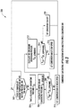
FIG. 2 is a control flow diagram of a first exemplary method of controlling the refrigeration system shown inFIG. 1 ; and -
FIG. 3 is a control flow diagram of a second exemplary method of controlling the refrigeration system shown inFIG. 1 . -
FIG. 1 illustrates arefrigeration system 10. In the exemplary embodiment,refrigeration system 10 is operably associated with a temperature controlled cargo container (not shown) configured to maintain a cargo located inside the cargo container at a selected temperature through the use ofrefrigeration system 10. The cargo container may be utilized to transport cargo via, for example, a truck, a train or a ship. Transportation refrigeration applications are distinct from other applications due to their wide range of operating conditions. For example, the ambient temperature may vary from 130 °F to -20 °F, and the cargo container may be set at a temperature between 100 °F and -22 °F. However,system 10 may be utilized in various other refrigeration applications. -
Refrigeration system 10 is powered by apower generation system 12, which generally includes anengine 14 that is fluidly coupled to afuel tank 16. Although described as a refrigeration system,system 10 may be any suitable environment conditioning system. For example,system 10 may be a cab air conditioning unit for a truck. -
Refrigeration system 10 generally includes acompressor 22, acondenser 24, anexpansion device 26, and anevaporator 28. As illustrated,system 10 may include areceiver 30, asubcooler 32, a liquidsuction heat exchanger 34, anaccumulator 36, and asuction modulation valve 38. -
Refrigeration system 10 is a closed loop system through which refrigerant is circulated in various states such as liquid and vapor. As such, a low temperature, low pressure superheated gas refrigerant is drawn intocompressor 22 through aconduit 40 fromevaporator 28. The refrigerant is compressed and the resulting high temperature, high pressure superheated gas is discharged fromcompressor 22 to condenser 24 through aconduit 42. - In
condenser 24, gaseous refrigerant is condensed into liquid as it gives up heat. The superheated gas refrigerant enterscondenser 24 and is de-superheated, condensed, and sub-cooled through a heat exchanger process with air forced acrosscondenser 24 by acondenser fan 44 to absorb heat. The liquid refrigerant is discharged fromcondenser 24 and supplied through aconduit 46 viareceiver 30 tosubcooler 32. The refrigerant is further sub-cooled by air fromcondenser fan 44 and is supplied through aconduit 48 to liquidsuction heat exchanger 34. - In the exemplary embodiment, liquid
suction heat exchanger 34 cools liquid refrigerant fromcondenser 24 against vaporized and/or vaporizing refrigerant fromevaporator 28. The cooled liquid refrigerant is subsequently supplied toevaporator 28 through aconduit 50. The cooled liquid refrigerant passes through metering or expansion device 26 (e.g., expansion valve), which converts the relatively higher temperature, high pressure sub-cooled liquid to a low temperature saturated liquid-vapor mixture. - The low temperature saturated liquid-vapor refrigerant mixture then enters
evaporator 28 where it boils and changes states to a superheated gas as it absorbs the required heat of vaporization from air in the container (or other heat exchange fluid). The low pressure superheated gas then passes in heat exchange relation withheat exchanger 34, where it is further heated to increase the superheat of the gas and vaporize any residual liquid droplets that may passevaporator 28. The superheated gas is then drawn into the inlet ofcompressor 22 and the cycle is repeated. - In the exemplary embodiment,
refrigeration system 10 includes ahot gas valve 53, amain heating valve 55, and abypass conduit 52 extending betweenconduit 42 downstream ofcompressor 22 andconduit 50 upstream ofevaporator 28.Bypass conduit 52 may be selectively utilized to force high temperature refrigerant fromcompressor 22 to flow directly toevaporator 28 for defrostingevaporator 28 in a cooling mode or for heating in a heating mode. Moreover,refrigeration system 10 may include an economizer cycle (not shown). -
Condenser fan 44 is utilized in the condenser cycle and, in some embodiments, more than onecondenser fan 44 may be utilized. Condenser fan(s) 44 may be variable speed condenser fans and/or a multi-speed condenser fans. Variablespeed condenser fans 44 may be operably associated with a variable frequency drive (VFD), andmulti-speed condenser fans 44 may be operably associated with a multi-speed drive (MSD). - Utilization of the variable/
multi-speed fan 44 facilitates adjustment or modulation of the condensing pressure/temperature ofsystem 10 by controlling the fan speed. For example, a lower condenser fan speed results in less power usage byfan 44. However, this causes a higher condensing pressure/temperature, which requires more compressor pressure lift and causes increased compressor power consumption and engine fuel usage. As such, a balance between compressor power and condenser fan power exists, andrefrigeration system 10 includes acontroller 60 configured to optimize control ofcondenser fan 44 to minimize total power consumption offan 44 andcompressor 22 and/or maximize fuel efficiency ofengine 14. As used herein, the term controller refers to an application specific integrated circuit (ASIC), an electronic circuit, a processor (shared, dedicated, or group) and memory that executes one or more software or firmware programs, a combinational logic circuit, and/or other suitable components that provide the described functionality. -
Controller 60 is configured to determine an optimum condensing pressure/temperature set point, which may be defined as adjusting the condenser fan speed to maintain this condensing pressure/temperature set point whilerefrigeration system 10 is operated with the lowest power consumption. The optimum condensing pressure/temperature may be calculated abstractly by equation (1) shown below. Further, the optimum pressure/temperature set points may be saved in a table, andcontroller 60 can search the table to obtain the optimum condensing pressure/temperature for given measured variables (e.g.., measured ambient temperature, evaporator outlet pressure or saturation temperature or box temperature, whether a vehicle has a run or stop status, and compressor speed). The determined optimum condensing pressure/temperature thus corresponds to a certain speed of the condenser fan.
- Accordingly,
controller 60 subsequently operatesfan 44 at a speed corresponding to the optimum condensing pressure/temperature set point (which is a function of the measured ambient temperature, evaporator outlet pressure/saturation temperature, and compressor speed) that provides the most fuel efficient conditions forsystem 10 with considering the transportation run effect on the condenser air flow. Fuel efficiency may be defined as the ratio ofsystem 10 capacity with fuel consumption. By use of equation (1) or the pre-saved table, the optimum condensing pressure/temperature (which corresponds to the highest system efficiency) can be obtained.Controller 60 can control the condensing pressure ofsystem 10 to reach or be within a predetermined range of the setpoint by changing the fan speed, such as with a proportional integral derivative (PID) controller forvariable speed fan 44 or logic control formultiple speed fan 44. - However, in some cases, the optimum condensing pressure/temperature defined by the function or table may not be the best value to calculate fan speed, because of simulation/calculation error and or failure to consider air flow effect when the vehicle is operating or not operating. Thus, a system power consumption measurement and trial process may be used to find the actual optimum condensing pressure/temperature. As such, the optimization control may be different for each of a variable
speed condenser fan 44 and amulti-speed condenser fan 44, as described herein in more detail. -
FIG. 2 illustrates anexemplary method 100 for minimizing the power and/or fuel consumption ofrefrigeration system 10 by specific control ofcondenser fan 44. In the exemplary embodiment,condenser fan 44 is a variable speed fan. -
Method 100 includes a two-level optimization having acoarse search 102 and afine search 104.Coarse search 102 generally includes determining a near-optimal condensing pressure/temperature setpoint, which is calculated with pre-defined functions based on off-line simulation results, as described herein.Variable speed fan 44 may then be set at a speed that produces and maintains the near-optimal condensing pressure/temperature setpoint. A condensing pressure/temperature setpoint may be updated according to the determined near-optimal condensing pressure/temperature whenever there are significant changes in environmental and/or operating conditions. To further improve the system efficiency,fine search 104 may be utilized to determine the optimal condensing pressure/temperature through perturbation, as described herein in more detail. - With further reference to
FIG. 2 ,method 100 includes, atstep 110, determining if a change in the ambient air temperature and/or compressor suction pressure has exceeded a predetermined threshold. If true, control proceeds to thecoarse search 102 and the near optimal condensing pressure/temperature is calculated atstep 112 by calculations using, for example, equation (1). Atstep 114, the condensing pressure/temperature set point is updated (e.g., once per second), and atstep 115,controller 60 modulates the fan speed to maintain the set point. Atstep 116, a reading of total power consumption ofrefrigeration system 10 is determined (e.g., measured by a current and voltage sensor) and set as current minimal power Wmin. At this point, the control returns to step 110. - If
step 110 is false, control proceeds to thefine search 104. Atstep 118, condenser fan speed is reduced by a predefined step change (e.g., by 1%). Atstep 120, the total power consumption is again determined and set as current power Wcur. - At
step 122, it is determined whether Wcur is greater than Wmin. If false, control proceeds to step 124 where Wcur is set as the new minimal power Wmin, and control subsequently returns to step 110. Steps 110 -124 may be repeated until the Wcur is greater than Wmin, and then change the search direction (to step 126). - If
step 122 is true, control proceeds to step 126 and the condenser fan speed is increased by a predefined step change (e.g., by 1%). Atstep 128, the total power consumption is again determined and set as current power Wcur. Atstep 130, it is determined whether Wcur is greater than Wmin. - If false, control proceeds to step 132 where Wcur is set as the new minimal power Wmin and control subsequently returns to step 126. Steps 126-132 may be repeated until the Wcur is greater than Wmin, where the minimal power is reached. If
step 130 is true, control returns to step 110. - As such, the
fine search 104 starts from near-optimal setpoints and subsequently decreases/increases the condenser fan speed by a small predefined change. If total power is reduced, then the search is continued in the same direction (i.e., decreased or increased). Otherwise, the search is made in the opposite direction (increases/decreases the setpoint). If total power begins to increase, the set point cannot be improved anymore and is at the optimal condensing pressure/temperature. -
FIG. 3 illustrates anexemplary method 200 for minimizing power and/or fuel consumption ofrefrigeration system 10 by specific control ofcondenser fan 44. In the exemplary embodiment,condenser fan 44 is a multi-speed fan having a high-speed mode and a low-speed mode. However,multi-speed condenser fan 44 may have any number of modes that operate at various speeds. -
Method 200 includes control optimization to determine how to switchmulti-speed fan 44 among the different speed modes at different operating conditions. The condensing pressure/temperature is selected as the gauge variable, and threshold values (upper and lower bounds of condensing pressure/temperature) may be calculated by empirical functions and curve fitted with simulation results. - With further reference to
FIG. 3 ,method 200 includes, atstep 202, determining if a change in the ambient air temperature and/or compressor suction pressure has exceeded a predetermined threshold. If false, control returns to step 202. If true, atstep 204, condensing pressure Pcd is determined. Atstep 206, an upper bound condensing pressure Pcd_upbound is determined by an optimum pressure table in different conditions. This optimum pressure table may be defined by simulations. Upper and lower bounds are the pressure limits which determine the condenser fan status. When condensing pressure is above upper bound pressure, the condenser fan runs with high speed. When condensing pressure is below lower bound pressure, the condenser fan is off. When condensing pressure is between lower bound and upper bound pressure, the condenser fan runs with low speed. - At
step 208, it is determined whether Pcd is greater than Pcd_upbound. If true, atstep 210,multi-speed condenser fan 44 is operated in a first mode (e.g., high speed) and control returns to step 202. If false, atstep 212, a lower bound condensing pressure Pcd_lowbound is determined by the optimum pressure table in different conditions. - At
step 214, it is determined whether Pcd is greater than Pcd_lowbound. If true, atstep 216,multi-speed condenser fan 44 is operated in a second mode (e.g., low speed) and control returns to step 202. If false, atstep 218,condenser fan 44 is operated in a third mode (e.g., off) and control returns to step 202. - Described herein are systems and methods for minimizing power and/or fuel consumption of a refrigeration system by control optimization of one or more system condenser fans. The condenser fans may include variable speed and/or a multi-speed condenser fans. Control optimization for the variable speed fan includes determining a near-optimal condensing pressure/temperature based on environmental and system operating conditions and/or determining an optimal condensing pressure/temperature through system perturbation. Control optimization for the multi-speed condenser fan includes selecting a condensing pressure/temperature as a gauge variable, calculating upper and lower bound condensing pressures, and adjusting fan speed modes based on gauge variable relative to the upper and lower bounds.
- While the invention has been described in detail in connection with only a limited number of embodiments, it should be readily understood that the invention is not limited to such disclosed embodiments. Rather, the invention can be modified to incorporate any number of variations, alterations, substitutions or equivalent arrangements not heretofore described, but which are commensurate with the spirit and scope of the invention. Additionally, while various embodiments of the invention have been described, it is to be understood that aspects of the invention may include only some of the described embodiments. Accordingly, the invention is not to be seen as limited by the foregoing description, but is only limited by the scope of the appended claims.
- The following clauses set out aspects of the present disclosure, which may or may not be presently claimed, but which may form basis for future amendments and/or a divisional application:
- 1. A method of controlling a refrigeration system having a compressor, a condenser, an evaporator, and a variable speed condenser fan, the method comprising:
- determining if a change in an ambient temperature or a compressor suction pressure is greater than a predetermined threshold;
- determining a near-optimal condensing pressure/temperature if the change in the ambient temperature or the compressor suction pressure is above the predetermined threshold;
- setting a condensing pressure setpoint based on the determined near-optimal condensing pressure/temperature; and
- setting a speed of the variable speed condenser fan based on the condensing pressure setpoint.
- 2. The method of clause 1, wherein the step of determining the near-optimal condensing pressure/temperature comprises:
- determining the ambient temperature;
- determining a saturation temperature leaving the evaporator;
- determining a compressor speed; and
- determining the near-optimal condensing pressure/temperature based on the determined ambient temperature, saturation temperature leaving the evaporator, and compressor speed.
- 3. The method of clause 2, wherein the near-optimal condensing pressure/temperature is determined using the equation:

- 4. The method of clause 1, further comprising:
- determining a first total power consumption of the refrigeration system and setting as a current minimal power (Wmin);
- reducing a speed of the variable speed condenser fan by a predetermined amount;
- subsequently determining a second total power consumption of the refrigeration system and setting as a current power (Wcur); and
- determining if Wcur is greater than Wmin.
- 5. The method of clause 4, further comprising:
- increasing the speed of the variable speed condenser fan by a predetermined amount if Wcur is greater than Wmin;
- subsequently determining a third total power consumption of the refrigeration system and setting as current power (Wcur); and
- determining if Wcur is greater than Wmin.
- 6. A method of controlling a refrigeration system having a compressor, a condenser, an evaporator, and a multi-speed condenser fan, the method comprising:
- determining if a change in the ambient temperature or a suction pressure is greater than a predetermined threshold;
- determining a condensing pressure (Pcd) if the change in the ambient temperature or the suction pressure is greater than the predetermined threshold.
- determining an upper bound condensing pressure (Pcd_upbound);
- determining a lower bound condensing pressure (Pcd_lowbound); and
- setting a speed of the multi-speed condenser fan based on the determined condensing pressure Pcd and at least one of the upper bound condensing pressure Pcd _upbound and the lower bound condensing pressure Pcd_lowbound.
- 7. The method of clause 6, wherein determining the condensing pressure Pcd comprises using an optimum pressure table defining optimum pressures at different conditions, wherein the conditions include ambient temperature, evaporator outlet saturation temperature or box temperature, vehicle run/stop status, and compressor speed.
- 8. The method of clause 6, wherein determining the upper bound condensing pressure Pcd_upbound comprises using an optimum pressure table defining optimum pressures at different conditions, wherein the conditions include ambient temperature, evaporator exit temperature or box temperature, vehicle run/stop status, and compressor speed.
- 9. The method of clause 6, wherein determining the lower bound condensing pressure Pcd_lowbound comprises using an optimum pressure table defining optimum pressures at different conditions, wherein the conditions are functions of ambient temperature, evaporator outlet saturation temperature/pressure, and compressor speed.
- 10. The method of clause 6, further comprising determining whether Pcd is greater than Pcd_upbound.
- 11. The method of
clause 10, further comprising operating the multi-speed condenser fan in a high speed mode if Pcd is greater than Pcd_upbound. - 12. The method of clause 6, further comprising determining whether Pcd is greater than Pcd_lowbound.
- 13. The method of
clause 12, further comprising operating the multi-speed condenser fan in a low speed mode if Pcd is greater than Pcd_lowbound. - 14. The method of
clause 12, further comprising turning off the multi-speed condenser fan if Pcd is less than or equal to Pcd_lowbound. - 15. A method of controlling a refrigeration system having a compressor, a condenser, an evaporator, a variable speed condenser fan, and a multi-speed condenser fan, the method comprising:
- determining if a change in an ambient temperature or a compressor suction pressure is greater than a predetermined threshold;
- controlling a speed of the variable speed condenser fan, comprising:
- determining a near-optimal condensing pressure/temperature if the change in the ambient temperature or the compressor suction pressure is above the predetermined threshold;
- setting a condensing pressure setpoint based on the determined near-optimal condensing pressure/temperature; and
- setting a speed of the variable speed condenser fan based on the condensing pressure setpoint; and
- controlling a speed of the multi-speed condenser fan, comprising:
- determining a condensing pressure (Pcd) if the change in the ambient temperature or the suction pressure is greater than the predetermined threshold.
- determining an upper bound condensing pressure (Pcd_upbound);
- determining a lower bound condensing pressure (Pcd_lowbound), and
- setting a speed of the multi-speed condenser fan based on the determined condensing pressure Pcd and at least one of the upper bound condensing pressure Pcd _upbound and the lower bound condensing pressure Pcd_lowbound.
Claims (10)
- A method of controlling a refrigeration system having a compressor, a condenser, an evaporator, and a multi-speed condenser fan, the method comprising:determining if a change in the ambient temperature or a suction pressure is greater than a predetermined threshold;determining a condensing pressure (Pcd) if the change in the ambient temperature or the suction pressure is greater than the predetermined threshold.determining an upper bound condensing pressure (Pcd_upbound);determining a lower bound condensing pressure (Pcd_lowbound); andsetting a speed of the multi-speed condenser fan based on the determined condensing pressure Pcd and at least one of the upper bound condensing pressure Pcd _upbound and the lower bound condensing pressure Pcd_lowbound.
- The method of claim 1, wherein determining the condensing pressure Pcd comprises using an optimum pressure table defining optimum pressures at different conditions, wherein the conditions include ambient temperature, evaporator outlet saturation temperature or box temperature, vehicle run/stop status, and compressor speed.
- The method of claim 1, wherein determining the upper bound condensing pressure Pcd_upbound comprises using an optimum pressure table defining optimum pressures at different conditions, wherein the conditions include ambient temperature, evaporator exit temperature or box temperature, vehicle run/stop status, and compressor speed.
- The method of claim 1, wherein determining the lower bound condensing pressure Pcd_lowbound comprises using an optimum pressure table defining optimum pressures at different conditions, wherein the conditions are functions of ambient temperature, evaporator outlet saturation temperature/pressure, and compressor speed.
- The method of claim 1, further comprising determining whether Pcd is greater than Pcd_upbound.
- The method of claim 5, further comprising operating the multi-speed condenser fan in a high speed mode if Pcd is greater than Pcd_upbound.
- The method of claim 1, further comprising determining whether Pcd is greater than Pcd_lowbound.
- The method of claim 7, further comprising operating the multi-speed condenser fan in a low speed mode if Pcd is greater than Pcd_lowbound.
- The method of claim 7, further comprising turning off the multi-speed condenser fan if Pcd is less than or equal to Pcd_lowbound.
- A method of controlling a refrigeration system having a compressor, a condenser, an evaporator, a variable speed condenser fan, and a multi-speed condenser fan, the method comprising:determining if a change in an ambient temperature or a compressor suction pressure is greater than a predetermined threshold;controlling a speed of the variable speed condenser fan, comprising:determining a near-optimal condensing pressure/temperature if the change in the ambient temperature or the compressor suction pressure is above the predetermined threshold;setting a condensing pressure setpoint based on the determined near-optimal condensing pressure/temperature; andsetting a speed of the variable speed condenser fan based on the condensing pressure setpoint; andcontrolling a speed of the multi-speed condenser fan, comprising:determining a condensing pressure (Pcd) if the change in the ambient temperature or the suction pressure is greater than the predetermined threshold.determining an upper bound condensing pressure (Pcd_upbound);determining a lower bound condensing pressure (Pcd_lowbound), andsetting a speed of the multi-speed condenser fan based on the determined condensing pressure Pcd and at least one of the upper bound condensing pressure Pcd _upbound and the lower bound condensing pressure Pcd _lowbound.
Applications Claiming Priority (3)
| Application Number | Priority Date | Filing Date | Title |
|---|---|---|---|
| CN201510089508.8A CN105987550B (en) | 2015-02-27 | 2015-02-27 | Refrigeration system condenser fan control |
| PCT/US2016/019775 WO2016138382A1 (en) | 2015-02-27 | 2016-02-26 | Refrigeration system condenser fan control |
| EP16709222.0A EP3262355B1 (en) | 2015-02-27 | 2016-02-26 | Refrigeration system condenser fan control |
Related Parent Applications (2)
| Application Number | Title | Priority Date | Filing Date |
|---|---|---|---|
| EP16709222.0A Division-Into EP3262355B1 (en) | 2015-02-27 | 2016-02-26 | Refrigeration system condenser fan control |
| EP16709222.0A Division EP3262355B1 (en) | 2015-02-27 | 2016-02-26 | Refrigeration system condenser fan control |
Publications (1)
| Publication Number | Publication Date |
|---|---|
| EP3901540A1 true EP3901540A1 (en) | 2021-10-27 |
Family
ID=55521838
Family Applications (2)
| Application Number | Title | Priority Date | Filing Date |
|---|---|---|---|
| EP21175729.9A Ceased EP3901540A1 (en) | 2015-02-27 | 2016-02-26 | Refrigeration system condenser fan control |
| EP16709222.0A Active EP3262355B1 (en) | 2015-02-27 | 2016-02-26 | Refrigeration system condenser fan control |
Family Applications After (1)
| Application Number | Title | Priority Date | Filing Date |
|---|---|---|---|
| EP16709222.0A Active EP3262355B1 (en) | 2015-02-27 | 2016-02-26 | Refrigeration system condenser fan control |
Country Status (6)
| Country | Link |
|---|---|
| US (1) | US10697683B2 (en) |
| EP (2) | EP3901540A1 (en) |
| CN (1) | CN105987550B (en) |
| ES (1) | ES2882663T3 (en) |
| RU (1) | RU2711902C2 (en) |
| WO (1) | WO2016138382A1 (en) |
Families Citing this family (24)
| Publication number | Priority date | Publication date | Assignee | Title |
|---|---|---|---|---|
| DE102013221516A1 (en) * | 2013-10-23 | 2015-04-23 | Bayerische Motoren Werke Aktiengesellschaft | An air supply device for a vehicle seat and method for operating the air supply device |
| DE102017114082A1 (en) * | 2017-06-26 | 2018-12-27 | Valeo Thermal Commercial Vehicles Germany GmbH | A process for hot gas defrosting in a transport refrigeration plant and transport refrigeration plant operable in a hot gas defrost mode |
| CN109210810A (en) * | 2017-07-04 | 2019-01-15 | 开利公司 | Refrigeration system and starting control method for refrigeration system |
| CN107906682B (en) * | 2017-11-03 | 2020-07-14 | 广东美的暖通设备有限公司 | Control method, device and air conditioner for an air conditioning system |
| US11156394B2 (en) | 2018-02-27 | 2021-10-26 | Johnson Controls Technology Company | Systems and methods for pressure control in a heating, ventilation, and air conditioning (HVAC) system |
| US11609033B2 (en) | 2018-04-26 | 2023-03-21 | Johnson Controls Tyco IP Holdings LLP | Condenser fan control system |
| CN109186141B (en) * | 2018-08-14 | 2020-09-15 | 四川虹美智能科技有限公司 | Supercooling economizer control method, supercooling control device and multi-split system |
| CN109099556A (en) * | 2018-08-27 | 2018-12-28 | 海信(山东)空调有限公司 | Low temperature refrigeration of air conditioner control method and air conditioner |
| CN109373622A (en) * | 2018-10-12 | 2019-02-22 | 广州市华德工业有限公司 | A kind of air-conditioning system and data center computer room air-conditioning |
| US10955165B2 (en) * | 2018-12-04 | 2021-03-23 | Lennox Industries Inc. | Method and system for supply-air re-circulation |
| US11371728B2 (en) | 2018-12-04 | 2022-06-28 | Lennox Industries Inc. | Method and system for utilizing a bypass humidifier for dehumidification during cooling |
| KR20200111067A (en) | 2019-03-18 | 2020-09-28 | 이동원 | Condensing pressure control method of heat pump |
| KR20200113559A (en) | 2019-03-25 | 2020-10-07 | 이동원 | Method of controlling surplus refrigerant of heat pump |
| EP3875874B1 (en) * | 2020-03-05 | 2025-05-21 | Thermo King LLC | Speed control strategies for a condenser fan in a refrigeration system |
| CN111750506A (en) * | 2020-07-06 | 2020-10-09 | 深圳市英维克科技股份有限公司 | Control system and control method of condensing fan |
| CN114126332B (en) | 2020-08-26 | 2023-06-02 | 广东美的暖通设备有限公司 | Air conditioning system |
| CN114274738A (en) * | 2020-09-28 | 2022-04-05 | 冷王公司 | Method and system for preserving cargo at ultra-low temperatures for extended periods of time |
| SE545019C2 (en) * | 2020-10-02 | 2023-02-28 | Envirotainer Eng Ab | Climate-control container and climate-control method for a container |
| US12140359B2 (en) | 2021-10-21 | 2024-11-12 | Copeland Lp | Climate control systems for use with high glide working fluids and methods for operation thereof |
| CN116945859A (en) * | 2022-04-18 | 2023-10-27 | 开利公司 | Refrigerating device, control method thereof and transport vehicle |
| US12529489B2 (en) * | 2022-07-11 | 2026-01-20 | Rheem Manufacturing Company | Enhanced heat pump defrost without use of auxiliary heat |
| CN115235155A (en) * | 2022-08-25 | 2022-10-25 | 长沙中谷智能设备制造有限公司 | A kind of intelligent cooling system and control method of automatic vending machine |
| CN115930370B (en) * | 2022-12-20 | 2024-11-29 | 珠海格力电器股份有限公司 | Air conditioner control method and air conditioner |
| CN116382370B (en) * | 2023-03-31 | 2024-10-29 | 杭州千岛净露水业有限公司 | Dew collector condensation temperature self-adaptive control calculation method and system |
Citations (5)
| Publication number | Priority date | Publication date | Assignee | Title |
|---|---|---|---|---|
| JPH1038392A (en) * | 1996-07-23 | 1998-02-13 | Sanyo Electric Co Ltd | Speed control device for blower for condenser |
| EP1873467A2 (en) * | 2004-10-28 | 2008-01-02 | Emerson Retail Services INC. | Variable speed condenser fan control system |
| US20130139529A1 (en) * | 2011-11-14 | 2013-06-06 | Liebert Corporation | Fan Speed Control For Air-Cooled Condenser In Precision Cooling |
| US20140223934A1 (en) * | 2013-02-12 | 2014-08-14 | National Refrigeration & Air Conditioning Canada Corp. | Condenser unit |
| US20140326002A1 (en) * | 2013-05-03 | 2014-11-06 | Parker-Hannifin Corporation | Indoor and outdoor ambient condition driven system |
Family Cites Families (24)
| Publication number | Priority date | Publication date | Assignee | Title |
|---|---|---|---|---|
| US5907957A (en) | 1997-12-23 | 1999-06-01 | Carrier Corporation | Discharge pressure control system for transport refrigeration unit using suction modulation |
| US6560980B2 (en) | 2000-04-10 | 2003-05-13 | Thermo King Corporation | Method and apparatus for controlling evaporator and condenser fans in a refrigeration system |
| RU2230265C2 (en) * | 2002-05-22 | 2004-06-10 | Малахов Анатолий Иванович | Operation method for vapor-compression cooling machine and cooling machine for method implementation |
| US6910341B2 (en) | 2003-09-26 | 2005-06-28 | Thermo King Corporation | Temperature control apparatus and method of operating the same |
| CN100480603C (en) | 2004-04-12 | 2009-04-22 | 约克国际公司 | Chiller sound reduction control system and method |
| US8051668B2 (en) * | 2004-10-28 | 2011-11-08 | Emerson Retail Services, Inc. | Condenser fan control system |
| EP1721765A1 (en) | 2005-05-04 | 2006-11-15 | Dometic Corporation | DC-powered HVAC system |
| US7878014B2 (en) | 2005-12-09 | 2011-02-01 | Emerson Climate Technologies, Inc. | Parallel condensing unit control system and method |
| CN101646911B (en) | 2007-02-14 | 2012-03-21 | 开利公司 | Optimization of air cooled chiller system operation |
| RU2488750C2 (en) * | 2008-05-21 | 2013-07-27 | Модайн Мэньюфэкчеринг Компани | Refrigerator with control of specified settings |
| US8745996B2 (en) * | 2008-10-01 | 2014-06-10 | Carrier Corporation | High-side pressure control for transcritical refrigeration system |
| US20100094466A1 (en) * | 2008-10-14 | 2010-04-15 | Libert Corporation | Integrated quiet and energy efficient modes of operation for air-cooled condenser |
| WO2011008649A2 (en) | 2009-07-13 | 2011-01-20 | Carrier Corporation | Transport refrigeration system, transport refrigeration unit, and methods for same |
| US9140489B2 (en) | 2009-08-10 | 2015-09-22 | Carrier Corporation | Power savings apparatus for transport refrigeration system, transport refrigeration unit, and methods for same |
| WO2012177720A1 (en) | 2011-06-22 | 2012-12-27 | Carrier Corporation | Condenser fan speed control for air conditioning system efficiency optimization |
| CN102518595A (en) * | 2011-12-13 | 2012-06-27 | Tcl空调器(中山)有限公司 | A method for controlling the speed of multi-connected outdoor fans |
| US8825184B2 (en) | 2012-03-26 | 2014-09-02 | Mitsubishi Electric Research Laboratories, Inc. | Multivariable optimization of operation of vapor compression systems |
| AU2013285537B2 (en) | 2012-07-02 | 2017-10-12 | Medizinische Universitat Wien | Complement split product C4d for the treatment of inflammatory conditions |
| DE112013004959T5 (en) * | 2012-10-10 | 2015-07-30 | Trane International Inc. | Variable fan speed control in HVAC systems and methods |
| CN103016382B (en) | 2012-12-21 | 2015-09-09 | 海信(山东)冰箱有限公司 | Refrigerator and condensation fan speed-adjusting and control system thereof and method |
| US9477235B2 (en) | 2013-02-18 | 2016-10-25 | Liebert Corporation | Methods of controlling a cooling system based on pressure differences across a scroll compressor |
| US9829233B2 (en) * | 2013-02-18 | 2017-11-28 | Liebert Corporation | Scroll compressor differential pressure control during compressor startup transitions |
| CN103292421A (en) * | 2013-06-17 | 2013-09-11 | 南京天加空调设备有限公司 | Multi-split refrigeration operation outer draught fan rotating speed control method |
| US9470445B2 (en) * | 2014-11-07 | 2016-10-18 | Emerson Climate Technologies, Inc. | Head pressure control |
-
2015
- 2015-02-27 CN CN201510089508.8A patent/CN105987550B/en active Active
-
2016
- 2016-02-26 ES ES16709222T patent/ES2882663T3/en active Active
- 2016-02-26 EP EP21175729.9A patent/EP3901540A1/en not_active Ceased
- 2016-02-26 WO PCT/US2016/019775 patent/WO2016138382A1/en not_active Ceased
- 2016-02-26 US US15/553,380 patent/US10697683B2/en active Active
- 2016-02-26 RU RU2017129752A patent/RU2711902C2/en active
- 2016-02-26 EP EP16709222.0A patent/EP3262355B1/en active Active
Patent Citations (5)
| Publication number | Priority date | Publication date | Assignee | Title |
|---|---|---|---|---|
| JPH1038392A (en) * | 1996-07-23 | 1998-02-13 | Sanyo Electric Co Ltd | Speed control device for blower for condenser |
| EP1873467A2 (en) * | 2004-10-28 | 2008-01-02 | Emerson Retail Services INC. | Variable speed condenser fan control system |
| US20130139529A1 (en) * | 2011-11-14 | 2013-06-06 | Liebert Corporation | Fan Speed Control For Air-Cooled Condenser In Precision Cooling |
| US20140223934A1 (en) * | 2013-02-12 | 2014-08-14 | National Refrigeration & Air Conditioning Canada Corp. | Condenser unit |
| US20140326002A1 (en) * | 2013-05-03 | 2014-11-06 | Parker-Hannifin Corporation | Indoor and outdoor ambient condition driven system |
Also Published As
| Publication number | Publication date |
|---|---|
| EP3262355B1 (en) | 2021-07-21 |
| ES2882663T3 (en) | 2021-12-02 |
| RU2017129752A3 (en) | 2019-07-24 |
| EP3262355A1 (en) | 2018-01-03 |
| RU2711902C2 (en) | 2020-01-23 |
| CN105987550A (en) | 2016-10-05 |
| RU2017129752A (en) | 2019-03-28 |
| WO2016138382A1 (en) | 2016-09-01 |
| CN105987550B (en) | 2021-04-09 |
| US20180073791A1 (en) | 2018-03-15 |
| US10697683B2 (en) | 2020-06-30 |
Similar Documents
| Publication | Publication Date | Title |
|---|---|---|
| EP3262355B1 (en) | Refrigeration system condenser fan control | |
| US9341398B2 (en) | Air conditioning system provided with an electronic expansion valve | |
| US8991201B2 (en) | Ejector cycle system | |
| EP2588819B1 (en) | Evaporator refrigerant saturation demand defrost | |
| US10107536B2 (en) | Transport refrigeration system and methods for same to address dynamic conditions | |
| CN110030776B (en) | Method for managing compressor start-up of a transport refrigeration system | |
| US12097451B2 (en) | Method for controlling a vapour compression system during gas bypass valve malfunction | |
| CN103673416A (en) | Control method for refrigerant flow quantity in automobile air conditioning system and automobile air conditioning system | |
| US8069684B2 (en) | Control of a refrigeration circuit with an internal heat exchanger | |
| EP3242999B1 (en) | Fuel cooling system and method | |
| US20140352913A1 (en) | Aircraft refrigeration unit evaporator heater | |
| US20130291575A1 (en) | Cooling system and method for operating same | |
| CN107624153B (en) | Staged expansion system and method | |
| WO2008080436A1 (en) | Superheat control for refrigeration circuit | |
| JP2025501533A (en) | Method for controlling cycle system and compression equipment - Patents.com | |
| JP7499615B2 (en) | Air Conditioning System | |
| WO2026073690A1 (en) | Defrost operation in refrigerated containers | |
| WO2026073679A1 (en) | Managing conditions in refrigerated containers | |
| HK1141072B (en) | A refrigeration circuit and method for operating such a circuit | |
| HK1141072A1 (en) | A refrigeration circuit and method for operating such a circuit | |
| HK1108022B (en) | Control of a refrigeration circuit with an internal heat exchanger |
Legal Events
| Date | Code | Title | Description |
|---|---|---|---|
| PUAI | Public reference made under article 153(3) epc to a published international application that has entered the european phase |
Free format text: ORIGINAL CODE: 0009012 |
|
| STAA | Information on the status of an ep patent application or granted ep patent |
Free format text: STATUS: THE APPLICATION HAS BEEN PUBLISHED |
|
| AC | Divisional application: reference to earlier application |
Ref document number: 3262355 Country of ref document: EP Kind code of ref document: P |
|
| AK | Designated contracting states |
Kind code of ref document: A1 Designated state(s): AL AT BE BG CH CY CZ DE DK EE ES FI FR GB GR HR HU IE IS IT LI LT LU LV MC MK MT NL NO PL PT RO RS SE SI SK SM TR |
|
| B565 | Issuance of search results under rule 164(2) epc |
Effective date: 20210903 |
|
| STAA | Information on the status of an ep patent application or granted ep patent |
Free format text: STATUS: REQUEST FOR EXAMINATION WAS MADE |
|
| 17P | Request for examination filed |
Effective date: 20220427 |
|
| RBV | Designated contracting states (corrected) |
Designated state(s): AL AT BE BG CH CY CZ DE DK EE ES FI FR GB GR HR HU IE IS IT LI LT LU LV MC MK MT NL NO PL PT RO RS SE SI SK SM TR |
|
| STAA | Information on the status of an ep patent application or granted ep patent |
Free format text: STATUS: EXAMINATION IS IN PROGRESS |
|
| 17Q | First examination report despatched |
Effective date: 20230330 |
|
| P01 | Opt-out of the competence of the unified patent court (upc) registered |
Effective date: 20230527 |
|
| STAA | Information on the status of an ep patent application or granted ep patent |
Free format text: STATUS: THE APPLICATION HAS BEEN REFUSED |
|
| 18R | Application refused |
Effective date: 20250417 |