EP3901472B1 - Hydraulisches dämpfungssystem für ein hinteres tor einer rundballenpresse - Google Patents
Hydraulisches dämpfungssystem für ein hinteres tor einer rundballenpresse Download PDFInfo
- Publication number
- EP3901472B1 EP3901472B1 EP21167873.5A EP21167873A EP3901472B1 EP 3901472 B1 EP3901472 B1 EP 3901472B1 EP 21167873 A EP21167873 A EP 21167873A EP 3901472 B1 EP3901472 B1 EP 3901472B1
- Authority
- EP
- European Patent Office
- Prior art keywords
- fluid
- control valve
- flow rate
- branch line
- hydraulic system
- Prior art date
- Legal status (The legal status is an assumption and is not a legal conclusion. Google has not performed a legal analysis and makes no representation as to the accuracy of the status listed.)
- Active
Links
Images




Classifications
-
- A—HUMAN NECESSITIES
- A01—AGRICULTURE; FORESTRY; ANIMAL HUSBANDRY; HUNTING; TRAPPING; FISHING
- A01F—PROCESSING OF HARVESTED PRODUCE; HAY OR STRAW PRESSES; DEVICES FOR STORING AGRICULTURAL OR HORTICULTURAL PRODUCE
- A01F15/00—Baling presses for straw, hay or the like
- A01F15/08—Details
- A01F15/0875—Discharge devices
- A01F15/0883—Discharge devices for round balers
-
- F—MECHANICAL ENGINEERING; LIGHTING; HEATING; WEAPONS; BLASTING
- F15—FLUID-PRESSURE ACTUATORS; HYDRAULICS OR PNEUMATICS IN GENERAL
- F15B—SYSTEMS ACTING BY MEANS OF FLUIDS IN GENERAL; FLUID-PRESSURE ACTUATORS, e.g. SERVOMOTORS; DETAILS OF FLUID-PRESSURE SYSTEMS, NOT OTHERWISE PROVIDED FOR
- F15B11/00—Servomotor systems without provision for follow-up action; Circuits therefor
- F15B11/02—Systems essentially incorporating special features for controlling the speed or actuating force of an output member
- F15B11/04—Systems essentially incorporating special features for controlling the speed or actuating force of an output member for controlling the speed
- F15B11/0406—Systems essentially incorporating special features for controlling the speed or actuating force of an output member for controlling the speed during starting or stopping
-
- F—MECHANICAL ENGINEERING; LIGHTING; HEATING; WEAPONS; BLASTING
- F15—FLUID-PRESSURE ACTUATORS; HYDRAULICS OR PNEUMATICS IN GENERAL
- F15B—SYSTEMS ACTING BY MEANS OF FLUIDS IN GENERAL; FLUID-PRESSURE ACTUATORS, e.g. SERVOMOTORS; DETAILS OF FLUID-PRESSURE SYSTEMS, NOT OTHERWISE PROVIDED FOR
- F15B11/00—Servomotor systems without provision for follow-up action; Circuits therefor
- F15B11/02—Systems essentially incorporating special features for controlling the speed or actuating force of an output member
- F15B11/04—Systems essentially incorporating special features for controlling the speed or actuating force of an output member for controlling the speed
- F15B11/042—Systems essentially incorporating special features for controlling the speed or actuating force of an output member for controlling the speed by means in the feed line, i.e. "meter in"
- F15B11/0426—Systems essentially incorporating special features for controlling the speed or actuating force of an output member for controlling the speed by means in the feed line, i.e. "meter in" by controlling the number of pumps or parallel valves switched on
-
- F—MECHANICAL ENGINEERING; LIGHTING; HEATING; WEAPONS; BLASTING
- F15—FLUID-PRESSURE ACTUATORS; HYDRAULICS OR PNEUMATICS IN GENERAL
- F15B—SYSTEMS ACTING BY MEANS OF FLUIDS IN GENERAL; FLUID-PRESSURE ACTUATORS, e.g. SERVOMOTORS; DETAILS OF FLUID-PRESSURE SYSTEMS, NOT OTHERWISE PROVIDED FOR
- F15B11/00—Servomotor systems without provision for follow-up action; Circuits therefor
- F15B11/02—Systems essentially incorporating special features for controlling the speed or actuating force of an output member
- F15B11/04—Systems essentially incorporating special features for controlling the speed or actuating force of an output member for controlling the speed
- F15B11/046—Systems essentially incorporating special features for controlling the speed or actuating force of an output member for controlling the speed depending on the position of the working member
- F15B11/048—Systems essentially incorporating special features for controlling the speed or actuating force of an output member for controlling the speed depending on the position of the working member with deceleration control
-
- F—MECHANICAL ENGINEERING; LIGHTING; HEATING; WEAPONS; BLASTING
- F15—FLUID-PRESSURE ACTUATORS; HYDRAULICS OR PNEUMATICS IN GENERAL
- F15B—SYSTEMS ACTING BY MEANS OF FLUIDS IN GENERAL; FLUID-PRESSURE ACTUATORS, e.g. SERVOMOTORS; DETAILS OF FLUID-PRESSURE SYSTEMS, NOT OTHERWISE PROVIDED FOR
- F15B13/00—Details of servomotor systems ; Valves for servomotor systems
- F15B13/02—Fluid distribution or supply devices characterised by their adaptation to the control of servomotors
- F15B13/04—Fluid distribution or supply devices characterised by their adaptation to the control of servomotors for use with a single servomotor
- F15B13/0401—Valve members; Fluid interconnections therefor
-
- F—MECHANICAL ENGINEERING; LIGHTING; HEATING; WEAPONS; BLASTING
- F15—FLUID-PRESSURE ACTUATORS; HYDRAULICS OR PNEUMATICS IN GENERAL
- F15B—SYSTEMS ACTING BY MEANS OF FLUIDS IN GENERAL; FLUID-PRESSURE ACTUATORS, e.g. SERVOMOTORS; DETAILS OF FLUID-PRESSURE SYSTEMS, NOT OTHERWISE PROVIDED FOR
- F15B15/00—Fluid-actuated devices for displacing a member from one position to another; Gearing associated therewith
- F15B15/20—Other details, e.g. assembly with regulating devices
- F15B15/22—Other details, e.g. assembly with regulating devices for accelerating or decelerating the stroke
-
- F—MECHANICAL ENGINEERING; LIGHTING; HEATING; WEAPONS; BLASTING
- F15—FLUID-PRESSURE ACTUATORS; HYDRAULICS OR PNEUMATICS IN GENERAL
- F15B—SYSTEMS ACTING BY MEANS OF FLUIDS IN GENERAL; FLUID-PRESSURE ACTUATORS, e.g. SERVOMOTORS; DETAILS OF FLUID-PRESSURE SYSTEMS, NOT OTHERWISE PROVIDED FOR
- F15B2211/00—Circuits for servomotor systems
- F15B2211/40—Flow control
- F15B2211/405—Flow control characterised by the type of flow control means or valve
- F15B2211/40507—Flow control characterised by the type of flow control means or valve with constant throttles or orifices
-
- F—MECHANICAL ENGINEERING; LIGHTING; HEATING; WEAPONS; BLASTING
- F15—FLUID-PRESSURE ACTUATORS; HYDRAULICS OR PNEUMATICS IN GENERAL
- F15B—SYSTEMS ACTING BY MEANS OF FLUIDS IN GENERAL; FLUID-PRESSURE ACTUATORS, e.g. SERVOMOTORS; DETAILS OF FLUID-PRESSURE SYSTEMS, NOT OTHERWISE PROVIDED FOR
- F15B2211/00—Circuits for servomotor systems
- F15B2211/40—Flow control
- F15B2211/405—Flow control characterised by the type of flow control means or valve
- F15B2211/40576—Assemblies of multiple valves
- F15B2211/40584—Assemblies of multiple valves the flow control means arranged in parallel with a check valve
-
- F—MECHANICAL ENGINEERING; LIGHTING; HEATING; WEAPONS; BLASTING
- F15—FLUID-PRESSURE ACTUATORS; HYDRAULICS OR PNEUMATICS IN GENERAL
- F15B—SYSTEMS ACTING BY MEANS OF FLUIDS IN GENERAL; FLUID-PRESSURE ACTUATORS, e.g. SERVOMOTORS; DETAILS OF FLUID-PRESSURE SYSTEMS, NOT OTHERWISE PROVIDED FOR
- F15B2211/00—Circuits for servomotor systems
- F15B2211/40—Flow control
- F15B2211/405—Flow control characterised by the type of flow control means or valve
- F15B2211/40576—Assemblies of multiple valves
- F15B2211/40592—Assemblies of multiple valves with multiple valves in parallel flow paths
-
- F—MECHANICAL ENGINEERING; LIGHTING; HEATING; WEAPONS; BLASTING
- F15—FLUID-PRESSURE ACTUATORS; HYDRAULICS OR PNEUMATICS IN GENERAL
- F15B—SYSTEMS ACTING BY MEANS OF FLUIDS IN GENERAL; FLUID-PRESSURE ACTUATORS, e.g. SERVOMOTORS; DETAILS OF FLUID-PRESSURE SYSTEMS, NOT OTHERWISE PROVIDED FOR
- F15B2211/00—Circuits for servomotor systems
- F15B2211/40—Flow control
- F15B2211/415—Flow control characterised by the connections of the flow control means in the circuit
- F15B2211/41527—Flow control characterised by the connections of the flow control means in the circuit being connected to an output member and a directional control valve
-
- F—MECHANICAL ENGINEERING; LIGHTING; HEATING; WEAPONS; BLASTING
- F15—FLUID-PRESSURE ACTUATORS; HYDRAULICS OR PNEUMATICS IN GENERAL
- F15B—SYSTEMS ACTING BY MEANS OF FLUIDS IN GENERAL; FLUID-PRESSURE ACTUATORS, e.g. SERVOMOTORS; DETAILS OF FLUID-PRESSURE SYSTEMS, NOT OTHERWISE PROVIDED FOR
- F15B2211/00—Circuits for servomotor systems
- F15B2211/40—Flow control
- F15B2211/415—Flow control characterised by the connections of the flow control means in the circuit
- F15B2211/41527—Flow control characterised by the connections of the flow control means in the circuit being connected to an output member and a directional control valve
- F15B2211/41536—Flow control characterised by the connections of the flow control means in the circuit being connected to an output member and a directional control valve being connected to multiple ports of an output member
-
- F—MECHANICAL ENGINEERING; LIGHTING; HEATING; WEAPONS; BLASTING
- F15—FLUID-PRESSURE ACTUATORS; HYDRAULICS OR PNEUMATICS IN GENERAL
- F15B—SYSTEMS ACTING BY MEANS OF FLUIDS IN GENERAL; FLUID-PRESSURE ACTUATORS, e.g. SERVOMOTORS; DETAILS OF FLUID-PRESSURE SYSTEMS, NOT OTHERWISE PROVIDED FOR
- F15B2211/00—Circuits for servomotor systems
- F15B2211/40—Flow control
- F15B2211/42—Flow control characterised by the type of actuation
- F15B2211/426—Flow control characterised by the type of actuation electrically or electronically
-
- F—MECHANICAL ENGINEERING; LIGHTING; HEATING; WEAPONS; BLASTING
- F15—FLUID-PRESSURE ACTUATORS; HYDRAULICS OR PNEUMATICS IN GENERAL
- F15B—SYSTEMS ACTING BY MEANS OF FLUIDS IN GENERAL; FLUID-PRESSURE ACTUATORS, e.g. SERVOMOTORS; DETAILS OF FLUID-PRESSURE SYSTEMS, NOT OTHERWISE PROVIDED FOR
- F15B2211/00—Circuits for servomotor systems
- F15B2211/60—Circuit components or control therefor
- F15B2211/665—Methods of control using electronic components
- F15B2211/6654—Flow rate control
-
- F—MECHANICAL ENGINEERING; LIGHTING; HEATING; WEAPONS; BLASTING
- F15—FLUID-PRESSURE ACTUATORS; HYDRAULICS OR PNEUMATICS IN GENERAL
- F15B—SYSTEMS ACTING BY MEANS OF FLUIDS IN GENERAL; FLUID-PRESSURE ACTUATORS, e.g. SERVOMOTORS; DETAILS OF FLUID-PRESSURE SYSTEMS, NOT OTHERWISE PROVIDED FOR
- F15B2211/00—Circuits for servomotor systems
- F15B2211/70—Output members, e.g. hydraulic motors or cylinders or control therefor
- F15B2211/705—Output members, e.g. hydraulic motors or cylinders or control therefor characterised by the type of output members or actuators
- F15B2211/7051—Linear output members
- F15B2211/7053—Double-acting output members
-
- F—MECHANICAL ENGINEERING; LIGHTING; HEATING; WEAPONS; BLASTING
- F15—FLUID-PRESSURE ACTUATORS; HYDRAULICS OR PNEUMATICS IN GENERAL
- F15B—SYSTEMS ACTING BY MEANS OF FLUIDS IN GENERAL; FLUID-PRESSURE ACTUATORS, e.g. SERVOMOTORS; DETAILS OF FLUID-PRESSURE SYSTEMS, NOT OTHERWISE PROVIDED FOR
- F15B2211/00—Circuits for servomotor systems
- F15B2211/70—Output members, e.g. hydraulic motors or cylinders or control therefor
- F15B2211/75—Control of speed of the output member
-
- F—MECHANICAL ENGINEERING; LIGHTING; HEATING; WEAPONS; BLASTING
- F15—FLUID-PRESSURE ACTUATORS; HYDRAULICS OR PNEUMATICS IN GENERAL
- F15B—SYSTEMS ACTING BY MEANS OF FLUIDS IN GENERAL; FLUID-PRESSURE ACTUATORS, e.g. SERVOMOTORS; DETAILS OF FLUID-PRESSURE SYSTEMS, NOT OTHERWISE PROVIDED FOR
- F15B2211/00—Circuits for servomotor systems
- F15B2211/70—Output members, e.g. hydraulic motors or cylinders or control therefor
- F15B2211/755—Control of acceleration or deceleration of the output member
-
- F—MECHANICAL ENGINEERING; LIGHTING; HEATING; WEAPONS; BLASTING
- F15—FLUID-PRESSURE ACTUATORS; HYDRAULICS OR PNEUMATICS IN GENERAL
- F15B—SYSTEMS ACTING BY MEANS OF FLUIDS IN GENERAL; FLUID-PRESSURE ACTUATORS, e.g. SERVOMOTORS; DETAILS OF FLUID-PRESSURE SYSTEMS, NOT OTHERWISE PROVIDED FOR
- F15B2211/00—Circuits for servomotor systems
- F15B2211/80—Other types of control related to particular problems or conditions
- F15B2211/85—Control during special operating conditions
- F15B2211/853—Control during special operating conditions during stopping
Definitions
- the invention generally relates to a hydraulic system for a baler implement.
- a baler implement e.g., a round baler, includes a body and a rear gate rotatably attached to the body.
- the body forms a baling chamber within which crop material is formed into a bale.
- the rear gate is moveable between a closed position for forming the bale, an open position for discharging the bale from the baling chamber, and at least one intermediate position disposed between the open position and the closed position.
- a hydraulic system is used to actuate the rear gate.
- the hydraulic system includes a hydraulic cylinder that interconnects the body and the rear gate. The hydraulic cylinder extends and retracts in response to a fluid signal to move the rear gate between the open position and the closed position.
- the hydraulic system includes a tank that is operable to store a supply of a fluid, and a pump that is disposed in fluid communication with the tank and that is operable to circulate the fluid through a fluid circuit.
- the hydraulic system further includes a hydraulic cylinder.
- the hydraulic cylinder has a housing that defines an interior, and a piston that is moveably disposed within the interior of the housing. The housing and the piston cooperate to define a first fluid volume on a first side of the piston and a second fluid volume on an opposing second side of the piston.
- the housing includes a first fluid port and a second fluid port, with each of the first fluid port and the second fluid port disposed in fluid communication with the first fluid volume of the hydraulic cylinder.
- a flow rate control valve (also referred to as first control valve) is moveable between a first position for directing fluid to or from the first fluid port at a first flow rate, and a second position for directing fluid to or from the second fluid port at a second flow rate.
- the second flow rate is different than the first flow rate.
- the fluid circuit includes a first circuit portion, a first branch line, and a second branch line.
- the first circuit portion is disposed in selective fluid communication with one of the pump and the tank.
- the first branch line is connected to and in fluid communication with the first circuit portion and the first fluid port of the hydraulic cylinder.
- the second branch line is connected to and in fluid communication with the first circuit portion and the second fluid port of the hydraulic cylinder.
- the flow rate control valve is a two position spool valve in which fluid communication through the first branch line is allowed at the first flow rate when the flow rate control valve is disposed in the first position, and fluid communication through the first branch line is blocked when the flow rate control valve is disposed in the second position.
- the baler implement includes a body forming a baling chamber.
- the rear gate is rotatably attached to the body and rotatable about a gate axis between a closed position, an open position, and at least one intermediate position disposed between the closed position and the open position.
- the first branch line includes the flow rate control valve.
- the second branch line may include a structure and/or feature that reduces or restricts fluid flow through the fluid circuit.
- the second branch line may include a flow restriction, e.g., an orifice, which is operable to allow fluid flow through the flow restriction at the second flow rate.
- the flow rate control valve is normally biased into the first position.
- the second flow rate is less than the first flow rate. In another implementation, however, the second flow rate may be less than the first flow rate.
- the housing includes a third fluid port that is disposed in fluid communication with the second fluid volume of the hydraulic cylinder.
- the fluid circuit includes a second circuit portion in fluid communication with the third fluid port.
- the second circuit portion is disposed in selective fluid communication with one of the pump and the tank.
- a flow direction control valve (also referred to as second control valve) is moveable between a first position and a second position.
- the first position of the flow direction control valve connects the pump and the first circuit portion of the fluid circuit in fluid communication and connects the tank and the second circuit portion of the fluid circuit in fluid communication.
- the second position of the flow direction control valve connects the first circuit portion of the fluid circuit and the tank in fluid communication and connects the second circuit portion of the fluid circuit and the pump in fluid communication.
- the flow direction control valve may further include a third position.
- the third position of the flow direction control valve directly connects the pump and the tank in fluid communication.
- the third position of the flow direction control valve blocks fluid communication to both the first circuit portion and the second circuit portion of the fluid circuit from both the pump and the tank.
- the hydraulic system includes a controller.
- the controller is disposed in communication with and operable to control movement of the flow rate control valve between the first position of the flow rate control valve and the second position of the flow rate control valve. Additionally, the controller is disposed in communication with and operable to control movement of the flow direction control valve between at least the first position of the flow direction control valve and the second position of the flow direction control valve.
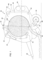
- baler implement 20 is generally shown at 20.
- the example implementation of the baler implement 20 shown in FIG. 1 is configured as a round baler.
- the teachings of the invention are described below with reference to the features of the example implementation of the baler implement 20 shown in FIG. 1 , i.e., the round baler. However, it should be appreciated that the teachings of the invention may be applied to other implementations and/or configurations of the baler implement 20 not shown or described herein.
- the baler implement 20 includes a frame 22.
- One or more ground engaging elements 24, such as but not limited to one or more wheels and/or tracks, are attached to and rotatably supported by the frame 22.
- a tongue 26 may be coupled to the frame 22 at a forward end of the frame 22.
- a hitch arrangement may be included with the tongue 26. The hitch arrangement may be used to attach the baler implement 20 to a traction unit, such as but not limited to an agricultural tractor.
- the baler implement 20 may be self-propelled, in which case the traction unit and the baler implement 20 are configured as a single, self-propelled vehicle.
- the baler implement 20 includes a housing or body 28 forming a baling chamber 30.
- the body 28 is attached to and supported by the frame 22.
- the body 28 may include one or more walls or panels that at least partially enclose and/or define the baling chamber 30.
- the baler implement 20 further includes a rear gate 32.
- the rear gate 32 is attached to and rotatably supported by the body 28.
- the rear gate 32 is positioned adjacent a rearward end of the frame 22 and is pivotably moveable about a gate axis 34.
- the gate axis 34 is generally horizontal and perpendicular to a central longitudinal axis of the frame 22.
- the rear gate 32 is moveable between a closed position for forming a bale 100 within the baling chamber 30, and an open position for discharging the bale 100 from the baling chamber 30.
- the rear gate 32 is further moveable to at least one intermediate position disposed between the open position and the closed position.
- the baler implement 20 includes a pick-up 36 disposed proximate the forward end of the frame 22.
- the pickup gathers crop material from a ground surface and directs the gathered crop material toward and into an inlet of the baling chamber 30.
- the pickup may include, but is not limited to tines, forks, augers, conveyors, baffles, etc., for gathering and moving the crop material.
- the baler implement 20 may be equipped with a pre-cutter (not shown), disposed between the pickup and the inlet. As such, the pre-cutter is disposed downstream of the pickup and upstream of the inlet relative to a direction of travel of the crop material. The pre-cutter cuts or chops the crop material into smaller pieces.
- the baler implement 20 may be configured as a variable chamber baler, or as a fixed chamber baler.
- the baler implement 20 shown in the Figures and described herein is depicted and described as a variable chamber baler.
- the variable chamber baler includes a plurality of longitudinally extending side-by-side forming belts 40 that are supported by a plurality of rollers 42.
- the bale 100 is formed by the forming belts 40 and one or more side walls of the housing.
- the crop material is directed through the inlet and into the baling chamber 30, whereby the forming belts 40 roll the crop material in a spiral fashion into the bale 100 having a cylindrical shape.
- the forming belts 40 apply a constant pressure to the crop material as the crop material is formed into the bale 100.
- a belt tensioner 44 continuously moves the forming belts 40 radially outward relative to a center of the cylindrical bale 100 as the diameter of the bale 100 increases.
- the belt tensioner 44 maintains the appropriate tension in the belts to obtain the desired density of the crop material.
- the belt tensioner 44 is moved by a first tension arm cylinder 46 and a second tension arm cylinder 48, both shown in FIGS. 2-6 .
- the first tension arm cylinder 46 and the second tension arm cylinder 48 extend and retract in response to a hydraulic signal to move the belt tensioner 44.
- the baler implement 20 includes a wrap system 50.
- the wrap system 50 is operable to wrap the bale 100 with a wrap material inside the baling chamber 30. Once the bale 100 is formed to a desired size, the wrap system 50 feeds the wrap material into the baling chamber 30 to wrap the bale 100 and thereby secure the crop material in a tight package and maintain the desired shape of the bale 100.
- the wrap material may include, but is not limited to, a twine, a net mesh, or a solid plastic wrap. Movement of the gate into the open position simultaneously moves the forming belts 40 clear of the formed bale 100, and allows the formed and wrapped bale 100 to be discharged through the rear of the baling chamber 30.
- the baler implement 20 includes a hydraulic system 52.
- the hydraulic system 52 is configured to operate the rear gate 32 of the baler implement 20. It should be appreciated that the hydraulic system 52 may be configured to operate other features and/or functions of the baler implement 20, such as but not limited to the first tension arm cylinder 46 and the second tension arm cylinder 48.
- the hydraulic system 52 includes a tank 54.
- the tank 54 is operable to store a supply of a fluid, e.g., hydraulic fluid.
- the tank 54 may alternatively be referred to as a reservoir or container capable of storing the supply of the fluid.
- a pump 56 is disposed in fluid communication with the tank 54.
- the pump 56 is operable to pressurize and/or circulate the fluid through a fluid circuit 58.
- the pump 56 draws the fluid from the tank 54 and circulates the fluid through the fluid circuit 58, through which the fluid is eventually returned to the tank 54.
- the specific type, configuration, and operation of the pump 56 are known to those skilled in the art, are not pertinent to the teachings of this invention, and are therefore not described in detail herein.
- the fluid circuit 58 includes a plurality of fluid passageways or portions that are connected together.
- the fluid passageways may include and be defined by individual components or combinations of components, including but are not limited to, rigid pipes, flexible hoses, connections, fittings, valves, valve bodies, etc.
- the fluid circuit 58 includes at least a first circuit portion 60, a second circuit portion 62, a first branch line 102, and a second branch line 104 described in greater detail below. While the fluid circuit 58 may include other fluid passageways, such as those leading to and from a tension arm valve body 64, the first tension arm cylinder 46, or the second tension arm cylinder 48, these other fluid passageways are not pertinent to the teachings of this invention, and are therefore not described in detail herein.
- the hydraulic system 52 includes a flow direction control valve 66.
- the flow direction control valve 66 is alternatively referred to herein as the second control valve.
- the flow direction control valve 66 is moveable between a first position and a second position to control the direction of fluid flow through the first circuit portion 60 and the second circuit portion 62 of the fluid circuit 58.
- the flow direction control valve 66 When the flow direction control valve 66 is disposed in its first position, the flow direction control valve 66 connects the pump 56 and the first circuit portion 60 of the fluid circuit 58 in fluid communication and connects the tank 54 and the second circuit portion 62 of the fluid circuit 58 in fluid communication.
- the flow direction control valve 66 When the flow direction control valve 66 is disposed in its second position, the flow direction control valve 66 connects the first circuit portion 60 of the fluid circuit 58 and the tank 54 in fluid communication and the second circuit portion 62 of the fluid circuit 58 and the pump 56 in fluid communication.
- the flow direction control valve 66 further includes a third position.
- the flow direction control valve 66 When the flow direction control valve 66 is disposed in its third position, the flow direction control valve 66 directly connects the pump 56 and the tank 54 in fluid communication and blocks fluid communication to both the first circuit portion 60 and the second circuit portion 62 of the fluid circuit 58 from both the pump 56 and the tank 54.
- the flow direction control valve 66 may include a three-position spool valve or some other equivalent valve structure. In the implementation described herein, the flow direction control valve 66 is normally biased into the third position.
- the flow direction control valve 66 may include one or more electrically actuated solenoids and/or biasing devices, e.g., springs, to move the flow direction control valve 66 between the different positions of the flow direction control valve 66. It should be appreciated that other valve types and/or combination of valves may be used to provide the functionality of the flow direction control valve 66 described herein.
- the baler implement 20 includes at least one hydraulic gate cylinder 68. While the example implementation shown in Figures 2-6 includes only one hydraulic gate cylinder 68, it should be appreciated that the hydraulic system 52 may include multiple hydraulic gate cylinders 68. As shown in FIGS. 2-6 , the hydraulic gate cylinder 68 includes a housing 106 defining an interior 108 and a piston 110 moveably disposed within the interior 108 of the housing 106. The housing 106 and the piston 110 cooperating to define a first fluid volume 112 on a first side of the piston 110 and a second fluid volume 114 on an opposing second side of the piston 110. A rod 72 is fixedly attached to and moveable with the piston 110.
- the housing 106 defines a first fluid port 74, a second fluid port 76, and a third fluid port 116. Both the first fluid port 74 and the second fluid port 76 are disposed in fluid communication with the first fluid volume 112 of the hydraulic gate cylinder 68. The third fluid port 116 is disposed in fluid communication with the second fluid volume 114 of the hydraulic gate cylinder 68.
- the hydraulic gate cylinder 68 is operable to extend and retract the rod 72 relative to the housing 106 to raise and lower the rear gate 32.
- fluid flow into the first fluid volume 112 and out of the second fluid volume 114 moves the piston 110 and the rod 72 in a first direction to extend the hydraulic gate cylinder 68 and raise the rear gate 32.
- fluid flow into the second fluid volume 114 and out of the first fluid volume 112 moves the piston 110 and the rod 72 in an opposite second direction to retract the hydraulic gate cylinder 68 and lower the rear gate 32.
- the first circuit portion 60 is disposed in selective fluid communication with one of the pump 56 and the tank 54, via the flow direction control valve 66.
- the first branch line 102 is connected to and in fluid communication with the first circuit portion 60.
- the first branch line 102 is further attached and/or directly connected to the first fluid port 74 of the hydraulic gate cylinder 68.
- the second branch line 104 is connected to and in fluid communication with the first circuit portion 60.
- the second branch line 104 is further attached and/or directly connected to the second fluid port 76 of the hydraulic gate cylinder 68.
- a flow rate control valve 80 is positioned between a location 86 at which the first circuit portion 60 and the second branch line 104 are connected, and the first fluid port 74 of the hydraulic gate cylinder 68.
- the flow rate control valve 80 is alternatively referred to herein as the first control valve.
- the flow rate control valve 80 is selectively moveable between a first position and a second position.
- the flow rate control valve 80 allows full fluid communication through the first branch line 102 to direct fluid to or from the first fluid port 74 at a first flow rate, to move the rear gate 32 at a first speed.
- the flow rate control valve 80 closes fluid communication through the second branch line 104.
- the flow rate control valve 80 When the flow rate control valve 80 is disposed in its second position, the flow rate control valve 80 closes fluid communication through the first branch line 102 and opens fluid communication through the second branch line 104 to direct fluid through the second branch line 104 and to or from the second fluid port 76 at a second flow rate, to move the rear gate 32 at a second speed.
- the flow rate control valve 80 is a two-position spool valve. In the implementation described herein, the flow rate control valve 80 is normally biased into its first position.
- the flow rate control valve 80 may include an electrically controlled solenoid that actuates an internal hydraulic pilot to move between the first and second position of the flow rate control valve 80. It should be appreciated that the flow rate control valve 80 may differ from the example implementation shown in the Figures and described herein.
- the flow rate control valve 80 may include a proportional valve to vary the fluid flow rate therethrough. It should be appreciated that other valve types and/or combination of valves may be used to provide the functionality of the flow rate control valve 80 described herein.
- a flow restriction 88 may be disposed within the second branch line 104.
- the flow restriction 88 may include an orifice plate or some other equivalent structure capable of restricting the fluid flow through the second branch line 104 to a rate that is different from, e.g., less than, a fluid flow rate through the flow rate control valve 80 and the first branch portion 102 when disposed in its first position.
- the flow restriction 88 may alternatively include a fluid passageway, e.g., hose or rigid pipe, etc., having a smaller cross sectional area relative to the cross sectional area of the first circuit portion 60 of the fluid circuit 58, thereby restricting fluid flow through the second branch line 104 relative to the fluid flow through the first branch line 102.
- the second circuit portion 62 is disposed in selective fluid communication with one of the pump 56 and the tank 54 via the flow direction control valve 66.
- the second circuit portion 62 is attached and/or directly connected to the third fluid port 116.
- the baler implement 20 further includes a controller 90.
- the controller 90 is disposed in communication with and operable to control movement of the flow rate control valve 80 between the first position of the flow rate control valve 80 and the second position of the flow rate control valve 80. Additionally, the controller 90 is disposed in communication with and operable to control movement of the flow direction control valve 66 between at least the first position of the flow direction control valve 66 and the second position of the flow direction control valve 66.
- the controller 90 may be configured to send a control signal, such as but not limited to an electrical signal, to the flow rate control valve 80 and/or the flow direction control valve 66 to move each between their respective positions.
- the controller 90 may alternatively be referred to as a computing device, a computer, a module, a control module, a control unit, etc.
- the controller 90 is operable to control the operation of the flow rate control valve 80 and the flow direction control valve 66.
- the controller 90 includes a processor 92, a memory 94, and all software, hardware, algorithms, connections, sensors 98, etc., necessary to manage and control the operation of the flow rate control valve 80 and the flow direction control valve 66.
- a method may be embodied as a program or algorithm operable on the controller 90.
- controller 90 may include any device capable of analyzing data from various sensors, comparing data, making the necessary decisions required to control the operation of the flow rate control valve 80 and the flow direction control valve 66, and executing the required tasks necessary to control the operation of the flow rate control valve 80 and the flow direction control valve 66.
- the controller 90 may be embodied as one or multiple digital computers or host machines each having one or more processors, read only memory (ROM), random access memory (RAM), electrically-programmable read only memory (EPROM), optical drives, magnetic drives, etc., a high-speed clock, analog-to-digital (A/D) circuitry, digital-to-analog (D/A) circuitry, and any required input/output (I/O) circuitry, I/O devices, and communication interfaces, as well as signal conditioning and buffer electronics.
- ROM read only memory
- RAM random access memory
- EPROM electrically-programmable read only memory
- optical drives magnetic drives, etc.
- a high-speed clock analog-to-digital (A/D) circuitry
- D/A digital-to-analog
- I/O input/output
- the computer-readable memory 94 may include any non-transitory/tangible medium which participates in providing data or computer-readable instructions.
- the memory 94 may be non-volatile or volatile.
- Non-volatile media may include, for example, optical or magnetic disks and other persistent memory.
- Example volatile media may include dynamic random access memory (DRAM), which may constitute a main memory.
- DRAM dynamic random access memory
- Other examples of embodiments for the memory 94 may include a floppy, flexible disk, or hard disk, magnetic tape or other magnetic medium, a CD-ROM, DVD, and/or any other optical medium, as well as other possible memory devices such as flash memory.
- the controller 90 includes the tangible, non-transitory memory 94 on which are recorded computer-executable instructions, including a valve control algorithm 96.
- the processor 92 of the controller 90 is configured for executing the valve control algorithm 96.
- the valve control algorithm 96 implements a method of controlling the flow direction control valve 66 and the flow rate control valve 80.
- the flow direction control valve 66 is controllable into the first position of the flow direction control valve 66 to extend the rod 72 and raise the rear gate 32.
- the flow direction control valve 66 directs the fluid from the pump 56, through the first circuit portion 60 of the fluid circuit 58 and into either the first branch line 102 and the first fluid port 74 or the second branch line 104 and the second fluid port 76, while directing fluid from the third fluid port 116 through the second circuit portion 62 of the fluid circuit 58 to the tank 54.
- the flow direction control valve 66 is controllable into the second position of the flow direction control valve 66 to retract the rod 72 and lower the rear gate 32.
- the flow direction control valve 66 directs the fluid from the pump 56, through the second circuit portion 62 of the fluid circuit 58 and into the third fluid port 116, while directing fluid from the first fluid volume, through either the first fluid port 74 and the first branch line 102 or the second fluid port 76 and the second branch line 104, through the first circuit portion 60 of the fluid circuit 58 to the tank 54.
- the flow rate control valve 80 is controllable into the first position of the flow rate control valve 80 to provide a first fluid flow rate through the first branch line 102 of the fluid circuit 58 to move the rear gate 32 at a first speed. When disposed in its first position, the flow rate control valve 80 directs fluid flow through the flow rate control valve 80 and the first branch line 102 at the first fluid rate. The flow rate control valve 80 is controllable into the second position of the flow rate control valve 80 to provide a second fluid flow rate through the second branch line 104 of the fluid circuit 58 to move the rear gate 32 at a second speed.
- the flow rate control valve 80 When the flow rate control valve 80 is disposed in its second position, the flow rate control valve 80 closes fluid communication through the first branch line 102, and directs fluid flow through the flow rate control valve 80, the second branch line 104 and through the flow restriction 88 at the second fluid flow rate. Because of the flow restriction 88, the second fluid flow rate and the second speed are less than the first fluid flow rate and the first speed respectively.
- the flow rate control valve 80 may be controlled to either its first position or its second position, regardless of the direction of fluid flow through the first circuit portion 60 of the fluid circuit 58, i.e., regardless of whether the flow direction control valve 66 is disposed in its first position for raising the rear gate 32 or its second position for lowering the rear gate 32.
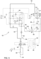
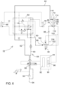
- FIGS. 3-6 show the first implementation of the hydraulic system 52 shown in FIG. 2 configured for different operations.
- pressurized fluid from the pump 56 is shown in thick solid lines, whereas fluid returning to tank 54 is shown in thick dashed lines.
- FIG. 3 shows the hydraulic system 52 in a first configuration, in which the hydraulic system 52 is configured to raise the rear gate 32 at a first speed.
- FIG. 4 shows the hydraulic system 52 in a second configuration, in which the hydraulic system 52 is configured to raise the rear gate 32 at a second speed.
- FIG. 5 shows the hydraulic system 52 in a third configuration, in which the hydraulic system 52 is configured to lower the rear gate 32 at a first speed.
- FIG. 6 shows the hydraulic system 52 in fourth configuration, in which the hydraulic system 52 is configured to lower the rear gate 32 at a second speed.
- the flow direction control valve 66 is shown controlled into the first position of the flow direction control valve 66
- the flow rate control valve 80 is shown controlled into the first position of the flow rate control valve 80.
- pressurized fluid from the pump 56 is directed through the first circuit portion 60 of the fluid circuit 58 to the first branch line 102, through the flow rate control valve 80, and to the first fluid port 74 of the hydraulic gate cylinder 68.
- Fluid communication through the second branch line 104 is blocked, such that no fluid flows through the second fluid port 76.
- Fluid from the third fluid port 116 of the hydraulic gate cylinders 68 is directed through the second circuit portion 62 of the fluid circuit 58 back to the tank 54.
- the flow rate control valve 80 is positioned in its first position, such that the fluid moving through the first branch line 102 moves directly through the flow rate control valve 80 at the first fluid flow rate. In this configuration, the rear gate 32 is moved toward the open position at the first speed.
- the flow direction control valve 66 is shown controlled into the first position of the flow direction control valve 66
- the flow rate control valve 80 is shown controlled into the second position of the flow rate control valve 80.
- pressurized fluid from the pump 56 is directed through the first circuit portion 60 of the fluid circuit 58 to the second branch line 104 and then to the second fluid port 76 of the hydraulic gate cylinder 68.
- Fluid flow through the first branch line 102 is blocked, such that no fluid flows through the first fluid port 74.
- Fluid from the third fluid port 116 of the hydraulic gate cylinder 68 is directed through the second circuit portion 62 of the fluid circuit 58 back to the tank 54.
- the flow rate control valve 80 is positioned in its second position, such that the fluid moving through the first branch line 102 is blocked by the flow rate control valve 80. Fluid is directed through the second branch line 104 and the flow restriction 88 included therein at the second fluid flow rate. In this configuration, the rear gate 32 is moved toward the open position at the second speed.
- the flow direction control valve 66 is shown controlled into the second position of the flow direction control valve 66
- the flow rate control valve 80 is shown controlled into the first position of the flow rate control valve 80.
- pressurized fluid from the pump 56 is directed through the second circuit portion 62 of the fluid circuit 58 to the third fluid port 116 of the hydraulic gate cylinder 68.
- Fluid from the first fluid volume 112 of the hydraulic gate cylinder 68 is directed through the first fluid port 74 of the hydraulic gate cylinder 68 and through the first branch line 102 back to the tank 54.
- Fluid flow through the second branch line 104 is blocked, such that no fluid flows through the second fluid port 76.
- the flow rate control valve 80 is positioned in its first position, such that the fluid moving through the first branch line 102 moves directly through the flow rate control valve 80 at the first fluid flow rate. In this configuration, the rear gate 32 is moved toward the closed position at the first speed.
- the flow direction control valve 66 is shown controlled into the second position of the flow direction control valve 66
- the flow rate control valve 80 is shown controlled into the second position of the flow rate control valve 80.
- pressurized fluid from the pump 56 is directed through the second circuit portion 62 of the fluid circuit 58 to the third fluid port 116 of the hydraulic gate cylinder 68.
- Fluid from the first fluid volume 112 of the hydraulic gate cylinder 68 is directed through the second fluid port 76 and the second branch line 104 to the first circuit portion 60 of the fluid circuit 58 and back to the tank 54.
- the flow rate control valve 80 is positioned in its second position, such that the fluid flow through the first branch line 102 is blocked by the flow rate control valve 80.
- Fluid flow is directed through the second branch line 104 and the flow restriction 88 included therein at the second fluid flow rate.
- the rear gate 32 is moved toward the closed position at the second speed.
- the flow direction control valve 66 and the flow rate control valve 80 may be controlled into the different configurations described above during different phases of various operations of the baler implement 20.
- the flow direction control valve 66 and the flow rate control valve 80 may be initially controlled into the first configuration shown in FIG. 3 through most of the travel of the rear gate 32 to move the rear gate 32 at the first speed, and then controlled into the second configuration shown in FIG. 4 through the remainder of the travel of the rear gate 32 to slow the speed of the rear gate 32 and move the rear gate 32 into the open position at a slower speed to prevent slamming the rear gate 32 open.
- the flow direction control valve 66 and the flow rate control valve 80 may be initially controlled into the third configuration shown in FIG.
- the rear gate 32 may be slowed and then stopped, while either opening or closing the rear gate 32, at an intermediate position between the open position and the closed position.
- the flow direction control valve 66 and the flow rate control valve 80 may be initially controlled into the first configuration shown in FIG. 3 through most of the travel of the rear gate 32 to move the rear gate 32 at the first speed, and then controlled into the second configuration shown in FIG.
- the flow direction control valve 66 and the flow rate control valve 80 may be initially controlled into the first configuration shown in FIG. 3 through most of the travel of the rear gate 32 to move the rear gate 32 at the first speed, and then controlled into the second configuration shown in FIG. 4 through the remainder of the travel of the rear gate 32 to slow the speed of the rear gate 32 and move the rear gate 32 into the open position at a slower speed to prevent slamming the rear gate 32 open.
- the controller 90 may communicate with one or more of the sensors 98.
- the sensors 98 provide data to the controller 90 related to at least one characteristic of the bale 100.
- the characteristic of the bale 100 may include, but is not limited to, a position of the bale 100 relative to the baling chamber 30 and/or the rear gate 32, a position of the rear gate 32 relative to the bale 100, a weight of the bale 100, a size of the bale 100, a formation status of the bale 100, a status of the wrap system 50, etc.
- the controller 90 may initiate at least one of a plurality of different gate control modes to control the rear gate 32 based on the data related to the characteristic of the bale 100.
- baler implement may include additional gate control modes not described herein.
- FIGS. 7-9 A first alternative embodiment of the hydraulic system is generally shown in FIGS. 7-9 .
- the reference numerals used to identify the features of the hydraulic system shown in FIGS. 2-6 are used to identify the same features of the hydraulic system shown in FIGS. 7-9 .
- the hydraulic system is shown in three different configurations.
- FIG. 7 shows the hydraulic system configured to raise the rear gate at the first speed.
- FIG. 8 shows the hydraulic system configured to lower the rear gate at the first speed.
- FIG. 9 shows the hydraulic system configured to lower the rear gate at the second speed.
- the flow direction control valve 66 is shown controlled into the first position of the flow direction control valve 66
- the flow rate control valve 80 is shown controlled into the second position of the flow rate control valve 80.
- pressurized fluid from the pump 56 is directed through the first circuit portion 60 of the fluid circuit 58 to the second branch line 104 and then to the second fluid port 76 of the hydraulic gate cylinder 68.
- Fluid from the third fluid port 116 of the hydraulic gate cylinder 68 is directed through the second circuit portion 62 of the fluid circuit 58 back to the tank 54.
- the flow rate control valve 80 is positioned in its second position, such that the fluid moving through the first branch line 102 is blocked by the flow rate control valve 80. Fluid is therefore forced through the second branch line 104.
- the flow direction control valve 66 is shown controlled into the second position of the flow direction control valve 66
- the flow rate control valve 80 is shown controlled into the first position of the flow rate control valve 80.
- pressurized fluid from the pump 56 is directed through the second circuit portion 62 of the fluid circuit 58 to the third fluid port 116 of the hydraulic gate cylinder 68.
- Fluid from the first fluid volume 112 of the hydraulic gate cylinder 68 is directed through the first fluid port 74 of the hydraulic gate cylinder 68 and through the first branch line 102 back to the tank 54.
- the flow rate control valve 80 is positioned in its first position, such that the fluid moving through the first branch line 102 moves directly through the flow rate control valve 80 at the first fluid flow rate.
- the flow direction control valve 66 is shown controlled into the second position of the flow direction control valve 66
- the flow rate control valve 80 is shown controlled into the second position of the flow rate control valve 80.
- pressurized fluid from the pump 56 is directed through the second circuit portion 62 of the fluid circuit 58 to the third fluid port 116 of the hydraulic gate cylinder 68.
- Fluid from the first fluid volume 112 of the hydraulic gate cylinder 68 is directed through the second fluid port 76 and the second branch line 104 to the first circuit portion 60 of the fluid circuit 58 and back to the tank 54.
- the flow rate control valve 80 is positioned in its second position, such that the fluid flow through the first branch line 102 is blocked by the flow rate control valve 80.
- fluid is forced through the second branch line 104 and the flow restriction 88 included therein at the second fluid flow rate.
- the rear gate 32 is moved toward the closed position at the second speed.
- FIGS. 10-12 A second alternative embodiment of the hydraulic system is generally shown in FIGS. 10-12 .
- the reference numerals used to identify the features of the hydraulic system shown in FIGS. 2-6 are used to identify the same features of the hydraulic system shown in FIGS. 10-12 .
- the hydraulic system is shown in three different configurations.
- FIG. 10 shows the hydraulic system configured to raise the rear gate at the first speed.
- FIG. 11 shows the hydraulic system configured to lower the rear gate at the first speed.
- FIG. 12 shows the hydraulic system configured to lower the rear gate at the second speed.
- the flow direction control valve 66 is shown controlled into the first position of the flow direction control valve 66, and the flow rate control valve 80 is shown controlled into the second position of the flow rate control valve 80.
- pressurized fluid from the pump 56 is directed through the first circuit portion 60 of the fluid circuit 58 to the second branch line 104.
- a port control valve 122 is disposed in fluid communication with the second branch line 104. The port control valve 122 is moveable between a first position allowing fluid flow through the second branch line 104, and a second position blocking fluid flow through the second branch line 104. As shown in FIG.
- the port control valve 122 is disposed in its first position, allowing fluid flow through the second branch line 104 and then to the second fluid port 76 of the hydraulic gate cylinder 68. Fluid from the third fluid port 116 of the hydraulic gate cylinder 68 is directed through the second circuit portion 62 of the fluid circuit 58 back to the tank 54.
- the flow rate control valve 80 is positioned in its second position, such that the fluid moving through the first branch line 102 is blocked by the flow rate control valve 80. In this direction, fluid is free to flow through the check valve 120 at the first fluid flow rate. It should be appreciated that little or minimal fluid may leak through the flow restriction 88. In this configuration, the rear gate 32 is moved toward the open position at the first speed.
- the flow direction control valve 66 is shown controlled into the second position of the flow direction control valve 66
- the flow rate control valve 80 is shown controlled into the first position of the flow rate control valve 80
- the port control valve 122 is controlled into the second position of the port control valve 122.
- pressurized fluid from the pump 56 is directed through the second circuit portion 62 of the fluid circuit 58 to the third fluid port 116 of the hydraulic gate cylinder 68.
- Fluid from the first fluid volume 112 of the hydraulic gate cylinder 68 is directed through the first fluid port 74 of the hydraulic gate cylinder 68 and through the first branch line 102 back to the tank 54.
- the flow rate control valve 80 is positioned in its first position, such that the fluid moving through the first branch line 102 moves directly through the flow rate control valve 80 at the first fluid flow rate. Because the port control valve 122 is positioned in its second position, i.e., its closed position, fluid flow through the second branch line 104 is blocked, and therefore no fluid flows through the second fluid port 76. In this configuration, the rear gate 32 is moved toward the closed position at the first speed.
- the flow direction control valve 66 is shown controlled into the second position of the flow direction control valve 66
- the flow rate control valve 80 is shown controlled into the second position of the flow rate control valve 80.
- the port control valve 122 is controlled into the first position of the port control valve 122.
- pressurized fluid from the pump 56 is directed through the second circuit portion 62 of the fluid circuit 58 to the third fluid port 116 of the hydraulic gate cylinder 68.
- Fluid from the first fluid volume 112 of the hydraulic gate cylinder 68 is directed through the second fluid port 76 and the second branch line 104 to the first circuit portion 60 of the fluid circuit 58 and back to the tank 54.
- the port control valve 122 is open allowing fluid flow through the second fluid port 76.
- the flow rate control valve 80 is positioned in its second position, such that the fluid flow through the first branch line 102 and the first fluid port 74 is blocked by the flow rate control valve 80. As such, fluid is forced through the second branch line 104 and the flow restriction 88 included therein at the second fluid flow rate. In this configuration, the rear gate 32 is moved toward the closed position at the second speed.
- FIGS. 13-15 A third alternative embodiment of the hydraulic system is generally shown in FIGS. 13-15 .
- the reference numerals used to identify the features of the hydraulic system shown in FIGS. 2-6 are used to identify the same features of the hydraulic system shown in FIGS. 13-15 .
- the hydraulic system is shown in three different configurations.
- FIG. 13 shows the hydraulic system configured to raise the rear gate at the first speed.
- FIG. 14 shows the hydraulic system configured to lower the rear gate at the first speed.
- FIG. 15 shows the hydraulic system configured to lower the rear gate at the second speed.
- the flow direction control valve 66 is shown controlled into the first position of the flow direction control valve 66
- the flow rate control valve 80 is shown controlled into the second position of the flow rate control valve 80.
- the flow rate control valve 80 includes a two position four port valve. In the first position of the flow rate control valve 80, fluid communication through the first branch line 102 is allowed and fluid communication through the second branch line 104 is blocked. In the second position of the flow rate control valve 80, fluid communication through the first branch line 102 is blocked and fluid communication through the second branch lie 104 is allowed. In this configuration, pressurized fluid from the pump 56 is directed through the first circuit portion 60 of the fluid circuit 58 to the second branch line 104, through the flow rate control valve 80, and to the second fluid port 76.
- Fluid from the third fluid port 116 of the hydraulic gate cylinder 68 is directed through the second circuit portion 62 of the fluid circuit 58 back to the tank 54.
- the flow rate control valve 80 is positioned in its second position, such that the fluid moving through the first branch line 102 is blocked by the flow rate control valve 80. As such, no fluid flows through the first fluid port 74. In this direction, fluid is free to flow through the check valve 120 at the first fluid flow rate. It should be appreciated that little or minimal fluid may leak through the flow restriction 88. In this configuration, the rear gate 32 is moved toward the open position at the first speed.
- the flow direction control valve 66 is shown controlled into the second position of the flow direction control valve 66
- the flow rate control valve 80 is shown controlled into the first position of the flow rate control valve 80.
- pressurized fluid from the pump 56 is directed through the second circuit portion 62 of the fluid circuit 58 to the third fluid port 116 of the hydraulic gate cylinder 68.
- Fluid from the first fluid volume 112 of the hydraulic gate cylinder 68 is directed through the first fluid port 74 of the hydraulic gate cylinder 68 and through the first branch line 102 back to the tank 54. Fluid flow through the second branch line 104 and the second fluid port 76 is blocked.
- the flow rate control valve 80 is positioned in its first position, such that the fluid moving through the first branch line 102 moves directly through the flow rate control valve 80 at the first fluid flow rate. In this configuration, the rear gate 32 is moved toward the closed position at the first speed.
- the flow direction control valve 66 is shown controlled into the second position of the flow direction control valve 66
- the flow rate control valve 80 is shown controlled into the second position of the flow rate control valve 80.
- pressurized fluid from the pump 56 is directed through the second circuit portion 62 of the fluid circuit 58 to the third fluid port 116 of the hydraulic gate cylinder 68.
- Fluid from the first fluid volume 112 of the hydraulic gate cylinder 68 is directed through the second fluid port 76, the second branch line 104, and the flow rate control valve 80 to the first circuit portion 60 of the fluid circuit 58 and back to the tank 54.
- the flow rate control valve 80 is positioned in its second position, such that the fluid flow through the first branch line 102 and the first fluid port 74 is blocked by the flow rate control valve 80. As such, fluid is directed through the second branch line 104 and the flow restriction 88 included therein at the second fluid flow rate. In this configuration, the rear gate 32 is moved toward the closed position at the second speed.
Landscapes
- Engineering & Computer Science (AREA)
- Physics & Mathematics (AREA)
- Fluid Mechanics (AREA)
- Mechanical Engineering (AREA)
- General Engineering & Computer Science (AREA)
- Life Sciences & Earth Sciences (AREA)
- Environmental Sciences (AREA)
- Fluid-Pressure Circuits (AREA)
Claims (12)
- Hydraulisches System (52) zum Betreiben eines hinteren Tores (32) eines Ballenpressenanbaugeräts (20), wobei das hydraulische System (52) Folgendes umfasst:einen Tank (54), betreibbar zum Speichern einer Fluidzufuhr;eine Pumpe (56), angeordnet in Fluidverbindung mit dem Tank (54) und betreibbar zum Umwälzen des Fluids durch einen Fluidkreis (58);einen hydraulischen Zylinder (68) mit einem Gehäuse (106), das einen Innenraum (108) definiert, und einem Kolben (110), der bewegbar innerhalb des Innenraums (108) des Gehäuses (106) angeordnet ist, wobei das Gehäuse (106) und der Kolben (110) zusammenwirken, um ein erstes Fluidvolumen (112) auf einer ersten Seite des Kolbens (110) und ein zweites Fluidvolumen (114) auf einer gegenüberliegenden zweiten Seite des Kolbens (110) zu definieren, wobei das Gehäuse (106) eine erste Fluidöffnung (74) und eine zweite Fluidöffnung (76) umfasst, die jeweils in Fluidverbindung mit dem ersten Fluidvolumen (112) des hydraulischen Zylinders (68) sind; undein erstes Steuerventil (80), bewegbar zwischen einer ersten Position zum Leiten von Fluid zu oder von der ersten Fluidöffnung (74) und einer zweiten Position zum Leiten von Fluid zu oder von der zweiten Fluidöffnung (76), wobei das erste Steuerventil (80) Fluid zu oder von der ersten Fluidöffnung (74) mit einer ersten Durchflussrate leitet, wenn in der ersten Position angeordnet, und Fluid zu oder von der zweiten Fluidöffnung (76) mit einer zweiten Durchflussrate leitet, wenn in der zweiten Position angeordnet, wobei die zweite Durchflussrate verschieden von der ersten Durchflussrate ist, und wobei der Fluidkreis (58) einen ersten Kreisabschnitt (60) in gezielter Fluidverbindung mit einem aus der Pumpe (56) und dem Tank (54), eine erste Verzweigungsleitung (102), verbunden mit und in Fluidverbindung mit dem ersten Kreisabschnitt (60) und der ersten Fluidöffnung (74) des hydraulischen Zylinders (68), und eine zweite Verzweigungsleitung (104), verbunden mit und in Fluidverbindung mit dem ersten Kreisabschnitt (60) und der zweiten Fluidöffnung (76) des hydraulischen Zylinders (68), umfasst,dadurch gekennzeichnet, dassdas erste Steuerventil (80) ein Zwei-Punkt-Schieberventil ist, in dem Fluidverbindung durch die erste Verzweigungsleitung (102) bei der ersten Durchflussrate erlaubt ist, wenn das erste Steuerventil (80) in der ersten Position angeordnet ist, und Fluidverbindung durch die erste Verzweigungsleitung (102) blockiert ist, wenn das erste Steuerventil (80) in der zweiten Position angeordnet ist.
- Hydraulisches System (52) nach Anspruch 1, wobei die erste Verzweigungsleitung (102) das erste Steuerventil (80) umfasst.
- Hydraulisches System (52) nach Anspruch 2, wobei die zweite Verzweigungsleitung (104) eine Strömungsdrossel (88) umfasst, die betreibbar ist, um Fluidströmung durch die Strömungsdrossel (88) bei der zweiten Durchflussrate zu ermöglichen.
- Hydraulisches System (52) nach zumindest einem der Ansprüche 1 bis 3, wobei das erste Steuerventil (80) im Ruhezustand in die erste Position vorgespannt ist.
- Hydraulisches System (52) nach zumindest einem der Ansprüche 1 bis 4, wobei die zweite Durchflussrate kleiner als die erste Durchflussrate ist.
- Hydraulisches System (52) nach zumindest einem der Ansprüche 1 bis 5, wobei das Gehäuse (106) eine dritte Fluidöffnung (116) in Fluidverbindung mit dem zweiten Fluidvolumen (114) des hydraulischen Zylinders (68) umfasst.
- Hydraulisches System (52) nach Anspruch 6, wobei der Fluidkreis (58) einen zweiten Kreisabschnitt (62) in Fluidverbindung mit der dritten Fluidöffnung (116) und in gezielter Fluidverbindung mit einem aus der Pumpe (56) und dem Tank (54) umfasst.
- Hydraulisches System (52) nach Anspruch 7, ferner umfassend ein zweites Steuerventil (66), bewegbar zwischen einer ersten Position, die die Pumpe (56) und den ersten Kreisabschnitt (60) des Fluidkreises (58) in Fluidverbindung verbindet und den Tank (54) und den zweiten Kreisabschnitt (62) des Fluidkreises (58) in Fluidverbindung verbindet, und einer zweiten Position, die den ersten Kreisabschnitt (60) des Fluidkreises (58) und den Tank (54) in Fluidverbindung verbindet und den zweiten Kreisabschnitt (62) des Fluidkreises (58) und die Pumpe (56) in Fluidverbindung verbindet.
- Hydraulisches System (52) nach Anspruch 8, wobei das zweite Steuerventil (66) eine dritte Position umfasst, die die Pumpe (56) und den Tank (54) in Fluidverbindung direkt verbindet, und wobei die dritte Position des zweiten Steuerventils (66) Fluidverbindung sowohl zum ersten Kreisabschnitt (60) als auch zum zweiten Kreisabschnitt (62) des Fluidkreises (58) sowohl von der Pumpe (56) als auch vom Tank (54) blockiert.
- Hydraulisches System (52) nach Anspruch 8, ferner umfassend eine Steuerung (90), wobei die Steuerung (90) angeordnet ist in Verbindung mit dem ersten Steuerventil (80) und betreibbar ist zum Steuern der Bewegung desselben zwischen der ersten Position des ersten Steuerventils (80) und der zweiten Position des ersten Steuerventils (80), und wobei die Steuerung (90) angeordnet ist in Verbindung mit dem zweiten Steuerventil (66) und betreibbar ist zum Steuern der Bewegung desselben zwischen zumindest der ersten Position des zweiten Steuerventils (66) und der zweiten Position des zweiten Steuerventils (66).
- Hydraulisches System (52) nach Anspruch 5, wobei Fluidverbindung durch die zweite Verzweigungsleitung (104) blockiert ist, wenn das erste Steuerventil (80) in der ersten Position angeordnet ist, und Fluidverbindung durch die zweite Verzweigungsleitung (104) erlaubt ist, wenn das erste Steuerventil (80) in der zweiten Position angeordnet ist.
- Hydraulisches System (52) nach Anspruch 2, ferner umfassend ein Öffnungssteuerventil (122) in Fluidverbindung mit der zweiten Verzweigungsleitung (104), wobei das Öffnungssteuerventil (122) zwischen einer ersten Position, die eine Fluidströmung durch die zweite Verzweigungsleitung (104) erlaubt, und einer zweiten Position, die Fluidströmung durch die zweite Verzweigungsleitung (104) blockiert, steuerbar ist.
Applications Claiming Priority (1)
| Application Number | Priority Date | Filing Date | Title |
|---|---|---|---|
| US16/855,663 US11547057B2 (en) | 2020-04-22 | 2020-04-22 | Hydraulic dampening system for a rear gate of a round baler |
Publications (2)
| Publication Number | Publication Date |
|---|---|
| EP3901472A1 EP3901472A1 (de) | 2021-10-27 |
| EP3901472B1 true EP3901472B1 (de) | 2024-08-07 |
Family
ID=75477948
Family Applications (1)
| Application Number | Title | Priority Date | Filing Date |
|---|---|---|---|
| EP21167873.5A Active EP3901472B1 (de) | 2020-04-22 | 2021-04-12 | Hydraulisches dämpfungssystem für ein hinteres tor einer rundballenpresse |
Country Status (2)
| Country | Link |
|---|---|
| US (1) | US11547057B2 (de) |
| EP (1) | EP3901472B1 (de) |
Families Citing this family (3)
| Publication number | Priority date | Publication date | Assignee | Title |
|---|---|---|---|---|
| IT201700093544A1 (it) * | 2017-08-11 | 2019-02-11 | Kverneland Group Ravenna Srl | Imballatore connettibile ad un trattore per realizzare balle rotonde e metodo per realizzare balle rotonde |
| US12336457B2 (en) | 2022-06-23 | 2025-06-24 | Deere & Company | Auxiliary pressure circuit for a round baler |
| US12622361B2 (en) * | 2023-08-15 | 2026-05-12 | Cnh Industrial America Llc | Regenerative tailgate circuit |
Family Cites Families (19)
| Publication number | Priority date | Publication date | Assignee | Title |
|---|---|---|---|---|
| US562305A (en) * | 1896-06-16 | Controlling mechanism for engines | ||
| US2211370A (en) * | 1937-07-01 | 1940-08-13 | Hydraulic Press Corp Inc | Hydraulic circuit |
| US2376519A (en) * | 1943-07-29 | 1945-05-22 | French Oil Mill Machinery | Valve control for presses and the like |
| US2857886A (en) * | 1954-09-14 | 1958-10-28 | Landis Tool Co | Traverse start control |
| US3608431A (en) * | 1969-07-14 | 1971-09-28 | Lummus Industries | Control system for the ram of vertically disposed fluid pressure cylinders |
| US3802318A (en) | 1970-05-09 | 1974-04-09 | K Sibbald | Apparatus for controlling machines |
| US4018136A (en) * | 1974-12-18 | 1977-04-19 | Kaetterhenry Lorell D | Hydraulic apparatus for controlling movement of a member under loading |
| DE2712878C2 (de) | 1977-03-24 | 1982-02-18 | Gebrüder Welger GmbH & Co KG, 3340 Wolfenbüttel | Rollballenpresse für landwirtschaftliche Halmgüter mit hydraulischer Verriegelung |
| FR2488771A1 (fr) * | 1980-08-20 | 1982-02-26 | Deere John Cie Francaise | Presse a balles cylindriques |
| JPS63163503U (de) | 1987-03-31 | 1988-10-25 | ||
| FR2684066B1 (fr) | 1991-11-26 | 1994-01-07 | Messier Bugatti | Systeme d'actionnement du verin de manóoeuvre d'un train d'atterrissage d'avion. |
| DE10303201C5 (de) | 2003-01-28 | 2015-03-12 | Lely Vermeer Maschinenfabrik GmbH | Rundballenpresse für landwirtschaftliche Halmgüter |
| US7849791B2 (en) | 2008-11-10 | 2010-12-14 | Cnh America Llc | Optimized baler tailgate cycle |
| US9107348B2 (en) | 2013-11-25 | 2015-08-18 | Cnh Industrial America Llc | Fluid circuit for bale ejection |
| US9113599B2 (en) | 2013-11-25 | 2015-08-25 | Cnh Industrial America Llc | Fluid circuit for bale ejection with restricted flow |
| US9980437B2 (en) * | 2014-03-25 | 2018-05-29 | CNH Industrial American LLC | Baling system having a bale position sensor |
| DE102015015858A1 (de) * | 2015-12-03 | 2017-06-08 | Sauter Feinmechanik Gmbh | Überwachungseinrichtung für Werkzeugrevolver |
| US10595465B2 (en) | 2016-04-08 | 2020-03-24 | Deere & Company | Agricultural baler including baler gate control system |
| IT201700093544A1 (it) | 2017-08-11 | 2019-02-11 | Kverneland Group Ravenna Srl | Imballatore connettibile ad un trattore per realizzare balle rotonde e metodo per realizzare balle rotonde |
-
2020
- 2020-04-22 US US16/855,663 patent/US11547057B2/en active Active
-
2021
- 2021-04-12 EP EP21167873.5A patent/EP3901472B1/de active Active
Also Published As
| Publication number | Publication date |
|---|---|
| US20210329843A1 (en) | 2021-10-28 |
| US11547057B2 (en) | 2023-01-10 |
| EP3901472A1 (de) | 2021-10-27 |
Similar Documents
| Publication | Publication Date | Title |
|---|---|---|
| EP3901472A1 (de) | Hydraulisches dämpfungssystem für ein hinteres tor einer rundballenpresse | |
| US7805914B2 (en) | Hydraulic bale kicker with optional weighing device | |
| EP2042028B1 (de) | Sequenz- und Zeitgabesteuerung für Vorrichtung zum Ausstoßen großer runder Ballen | |
| US5622104A (en) | Cylindrical baler having hydraulic circuit for controlling bale density and tailgate operation | |
| EP2183957B1 (de) | Verfahren zum Öffnen und Schließen einer Heckklappe für einen runden Ballen | |
| US4391187A (en) | Belt-tensioning system for round balers | |
| US10653067B1 (en) | Crop package accumulator | |
| US20150315836A1 (en) | Fluid circuit for bale ejection | |
| US11240967B2 (en) | Control system for a crop package accumulator and method of using same | |
| EP1444882B1 (de) | Rundballenpresse für landwirtschaftliche Halmgüter | |
| EP4223103A1 (de) | Windschutz mit variabler geometrie | |
| US11519429B2 (en) | Hydraulic system for baler implement gate | |
| US11105351B2 (en) | Agricultural baler with hydraulic flow controller | |
| EP3756448B1 (de) | Erntegutverteilungssystem für rundballenpresse | |
| US11612108B2 (en) | Hydraulic system for agricultural baler | |
| EP4218397A1 (de) | Windschutz mit variabler geometrie | |
| CA1173003A (en) | Automatic control linkage for round bale wagon | |
| US5025718A (en) | Machine for forming cylindrical bales of crop | |
| CA1175394A (en) | Control linkage for two function bale pickup | |
| EP1068781B1 (de) | Vorrichtung und Verfahren zur Positionierung lenkbarere Räder | |
| US12453314B2 (en) | Floating rotor and auger arrangement of agricultural baler | |
| US4428706A (en) | Interlock selector control valve for round bale wagon | |
| US4394103A (en) | Hydraulic system for a round bale wagon | |
| US12336457B2 (en) | Auxiliary pressure circuit for a round baler | |
| KR102600714B1 (ko) | 밸러의 출구 플랩을 제어하는 장치, 밸러 및 방법 |
Legal Events
| Date | Code | Title | Description |
|---|---|---|---|
| PUAI | Public reference made under article 153(3) epc to a published international application that has entered the european phase |
Free format text: ORIGINAL CODE: 0009012 |
|
| STAA | Information on the status of an ep patent application or granted ep patent |
Free format text: STATUS: THE APPLICATION HAS BEEN PUBLISHED |
|
| AK | Designated contracting states |
Kind code of ref document: A1 Designated state(s): AL AT BE BG CH CY CZ DE DK EE ES FI FR GB GR HR HU IE IS IT LI LT LU LV MC MK MT NL NO PL PT RO RS SE SI SK SM TR |
|
| B565 | Issuance of search results under rule 164(2) epc |
Effective date: 20210921 |
|
| STAA | Information on the status of an ep patent application or granted ep patent |
Free format text: STATUS: REQUEST FOR EXAMINATION WAS MADE |
|
| 17P | Request for examination filed |
Effective date: 20220428 |
|
| RBV | Designated contracting states (corrected) |
Designated state(s): AL AT BE BG CH CY CZ DE DK EE ES FI FR GB GR HR HU IE IS IT LI LT LU LV MC MK MT NL NO PL PT RO RS SE SI SK SM TR |
|
| STAA | Information on the status of an ep patent application or granted ep patent |
Free format text: STATUS: EXAMINATION IS IN PROGRESS |
|
| 17Q | First examination report despatched |
Effective date: 20221202 |
|
| GRAP | Despatch of communication of intention to grant a patent |
Free format text: ORIGINAL CODE: EPIDOSNIGR1 |
|
| STAA | Information on the status of an ep patent application or granted ep patent |
Free format text: STATUS: GRANT OF PATENT IS INTENDED |
|
| RIC1 | Information provided on ipc code assigned before grant |
Ipc: F15B 15/22 20060101ALN20240319BHEP Ipc: F15B 11/042 20060101ALI20240319BHEP Ipc: F15B 11/048 20060101ALI20240319BHEP Ipc: A01F 15/08 20060101ALI20240319BHEP Ipc: A01F 15/07 20060101ALI20240319BHEP Ipc: F15B 11/04 20060101AFI20240319BHEP |
|
| INTG | Intention to grant announced |
Effective date: 20240415 |
|
| GRAS | Grant fee paid |
Free format text: ORIGINAL CODE: EPIDOSNIGR3 |
|
| GRAA | (expected) grant |
Free format text: ORIGINAL CODE: 0009210 |
|
| STAA | Information on the status of an ep patent application or granted ep patent |
Free format text: STATUS: THE PATENT HAS BEEN GRANTED |
|
| AK | Designated contracting states |
Kind code of ref document: B1 Designated state(s): AL AT BE BG CH CY CZ DE DK EE ES FI FR GB GR HR HU IE IS IT LI LT LU LV MC MK MT NL NO PL PT RO RS SE SI SK SM TR |
|
| REG | Reference to a national code |
Ref country code: GB Ref legal event code: FG4D |
|
| REG | Reference to a national code |
Ref country code: CH Ref legal event code: EP |
|
| REG | Reference to a national code |
Ref country code: IE Ref legal event code: FG4D |
|
| REG | Reference to a national code |
Ref country code: DE Ref legal event code: R096 Ref document number: 602021016670 Country of ref document: DE |
|
| REG | Reference to a national code |
Ref country code: LT Ref legal event code: MG9D |
|
| REG | Reference to a national code |
Ref country code: NL Ref legal event code: MP Effective date: 20240807 |
|
| PG25 | Lapsed in a contracting state [announced via postgrant information from national office to epo] |
Ref country code: NO Free format text: LAPSE BECAUSE OF FAILURE TO SUBMIT A TRANSLATION OF THE DESCRIPTION OR TO PAY THE FEE WITHIN THE PRESCRIBED TIME-LIMIT Effective date: 20241107 |
|
| REG | Reference to a national code |
Ref country code: AT Ref legal event code: MK05 Ref document number: 1711220 Country of ref document: AT Kind code of ref document: T Effective date: 20240807 |
|
| PG25 | Lapsed in a contracting state [announced via postgrant information from national office to epo] |
Ref country code: NL Free format text: LAPSE BECAUSE OF FAILURE TO SUBMIT A TRANSLATION OF THE DESCRIPTION OR TO PAY THE FEE WITHIN THE PRESCRIBED TIME-LIMIT Effective date: 20240807 Ref country code: FI Free format text: LAPSE BECAUSE OF FAILURE TO SUBMIT A TRANSLATION OF THE DESCRIPTION OR TO PAY THE FEE WITHIN THE PRESCRIBED TIME-LIMIT Effective date: 20240807 Ref country code: PT Free format text: LAPSE BECAUSE OF FAILURE TO SUBMIT A TRANSLATION OF THE DESCRIPTION OR TO PAY THE FEE WITHIN THE PRESCRIBED TIME-LIMIT Effective date: 20241209 Ref country code: GR Free format text: LAPSE BECAUSE OF FAILURE TO SUBMIT A TRANSLATION OF THE DESCRIPTION OR TO PAY THE FEE WITHIN THE PRESCRIBED TIME-LIMIT Effective date: 20241108 Ref country code: PL Free format text: LAPSE BECAUSE OF FAILURE TO SUBMIT A TRANSLATION OF THE DESCRIPTION OR TO PAY THE FEE WITHIN THE PRESCRIBED TIME-LIMIT Effective date: 20240807 |
|
| PG25 | Lapsed in a contracting state [announced via postgrant information from national office to epo] |
Ref country code: BG Free format text: LAPSE BECAUSE OF FAILURE TO SUBMIT A TRANSLATION OF THE DESCRIPTION OR TO PAY THE FEE WITHIN THE PRESCRIBED TIME-LIMIT Effective date: 20240807 |
|
| PG25 | Lapsed in a contracting state [announced via postgrant information from national office to epo] |
Ref country code: LV Free format text: LAPSE BECAUSE OF FAILURE TO SUBMIT A TRANSLATION OF THE DESCRIPTION OR TO PAY THE FEE WITHIN THE PRESCRIBED TIME-LIMIT Effective date: 20240807 |
|
| PG25 | Lapsed in a contracting state [announced via postgrant information from national office to epo] |
Ref country code: IS Free format text: LAPSE BECAUSE OF FAILURE TO SUBMIT A TRANSLATION OF THE DESCRIPTION OR TO PAY THE FEE WITHIN THE PRESCRIBED TIME-LIMIT Effective date: 20241207 Ref country code: AT Free format text: LAPSE BECAUSE OF FAILURE TO SUBMIT A TRANSLATION OF THE DESCRIPTION OR TO PAY THE FEE WITHIN THE PRESCRIBED TIME-LIMIT Effective date: 20240807 |
|
| PG25 | Lapsed in a contracting state [announced via postgrant information from national office to epo] |
Ref country code: HR Free format text: LAPSE BECAUSE OF FAILURE TO SUBMIT A TRANSLATION OF THE DESCRIPTION OR TO PAY THE FEE WITHIN THE PRESCRIBED TIME-LIMIT Effective date: 20240807 |
|
| PG25 | Lapsed in a contracting state [announced via postgrant information from national office to epo] |
Ref country code: ES Free format text: LAPSE BECAUSE OF FAILURE TO SUBMIT A TRANSLATION OF THE DESCRIPTION OR TO PAY THE FEE WITHIN THE PRESCRIBED TIME-LIMIT Effective date: 20240807 Ref country code: RS Free format text: LAPSE BECAUSE OF FAILURE TO SUBMIT A TRANSLATION OF THE DESCRIPTION OR TO PAY THE FEE WITHIN THE PRESCRIBED TIME-LIMIT Effective date: 20241107 |
|
| PG25 | Lapsed in a contracting state [announced via postgrant information from national office to epo] |
Ref country code: RS Free format text: LAPSE BECAUSE OF FAILURE TO SUBMIT A TRANSLATION OF THE DESCRIPTION OR TO PAY THE FEE WITHIN THE PRESCRIBED TIME-LIMIT Effective date: 20241107 Ref country code: PT Free format text: LAPSE BECAUSE OF FAILURE TO SUBMIT A TRANSLATION OF THE DESCRIPTION OR TO PAY THE FEE WITHIN THE PRESCRIBED TIME-LIMIT Effective date: 20241209 Ref country code: PL Free format text: LAPSE BECAUSE OF FAILURE TO SUBMIT A TRANSLATION OF THE DESCRIPTION OR TO PAY THE FEE WITHIN THE PRESCRIBED TIME-LIMIT Effective date: 20240807 Ref country code: NO Free format text: LAPSE BECAUSE OF FAILURE TO SUBMIT A TRANSLATION OF THE DESCRIPTION OR TO PAY THE FEE WITHIN THE PRESCRIBED TIME-LIMIT Effective date: 20241107 Ref country code: NL Free format text: LAPSE BECAUSE OF FAILURE TO SUBMIT A TRANSLATION OF THE DESCRIPTION OR TO PAY THE FEE WITHIN THE PRESCRIBED TIME-LIMIT Effective date: 20240807 Ref country code: LV Free format text: LAPSE BECAUSE OF FAILURE TO SUBMIT A TRANSLATION OF THE DESCRIPTION OR TO PAY THE FEE WITHIN THE PRESCRIBED TIME-LIMIT Effective date: 20240807 Ref country code: IS Free format text: LAPSE BECAUSE OF FAILURE TO SUBMIT A TRANSLATION OF THE DESCRIPTION OR TO PAY THE FEE WITHIN THE PRESCRIBED TIME-LIMIT Effective date: 20241207 Ref country code: HR Free format text: LAPSE BECAUSE OF FAILURE TO SUBMIT A TRANSLATION OF THE DESCRIPTION OR TO PAY THE FEE WITHIN THE PRESCRIBED TIME-LIMIT Effective date: 20240807 Ref country code: GR Free format text: LAPSE BECAUSE OF FAILURE TO SUBMIT A TRANSLATION OF THE DESCRIPTION OR TO PAY THE FEE WITHIN THE PRESCRIBED TIME-LIMIT Effective date: 20241108 Ref country code: FI Free format text: LAPSE BECAUSE OF FAILURE TO SUBMIT A TRANSLATION OF THE DESCRIPTION OR TO PAY THE FEE WITHIN THE PRESCRIBED TIME-LIMIT Effective date: 20240807 Ref country code: ES Free format text: LAPSE BECAUSE OF FAILURE TO SUBMIT A TRANSLATION OF THE DESCRIPTION OR TO PAY THE FEE WITHIN THE PRESCRIBED TIME-LIMIT Effective date: 20240807 Ref country code: BG Free format text: LAPSE BECAUSE OF FAILURE TO SUBMIT A TRANSLATION OF THE DESCRIPTION OR TO PAY THE FEE WITHIN THE PRESCRIBED TIME-LIMIT Effective date: 20240807 Ref country code: AT Free format text: LAPSE BECAUSE OF FAILURE TO SUBMIT A TRANSLATION OF THE DESCRIPTION OR TO PAY THE FEE WITHIN THE PRESCRIBED TIME-LIMIT Effective date: 20240807 |
|
| PG25 | Lapsed in a contracting state [announced via postgrant information from national office to epo] |
Ref country code: SM Free format text: LAPSE BECAUSE OF FAILURE TO SUBMIT A TRANSLATION OF THE DESCRIPTION OR TO PAY THE FEE WITHIN THE PRESCRIBED TIME-LIMIT Effective date: 20240807 Ref country code: DK Free format text: LAPSE BECAUSE OF FAILURE TO SUBMIT A TRANSLATION OF THE DESCRIPTION OR TO PAY THE FEE WITHIN THE PRESCRIBED TIME-LIMIT Effective date: 20240807 |
|
| PG25 | Lapsed in a contracting state [announced via postgrant information from national office to epo] |
Ref country code: EE Free format text: LAPSE BECAUSE OF FAILURE TO SUBMIT A TRANSLATION OF THE DESCRIPTION OR TO PAY THE FEE WITHIN THE PRESCRIBED TIME-LIMIT Effective date: 20240807 |
|
| PG25 | Lapsed in a contracting state [announced via postgrant information from national office to epo] |
Ref country code: CZ Free format text: LAPSE BECAUSE OF FAILURE TO SUBMIT A TRANSLATION OF THE DESCRIPTION OR TO PAY THE FEE WITHIN THE PRESCRIBED TIME-LIMIT Effective date: 20240807 |
|
| PG25 | Lapsed in a contracting state [announced via postgrant information from national office to epo] |
Ref country code: SK Free format text: LAPSE BECAUSE OF FAILURE TO SUBMIT A TRANSLATION OF THE DESCRIPTION OR TO PAY THE FEE WITHIN THE PRESCRIBED TIME-LIMIT Effective date: 20240807 |
|
| REG | Reference to a national code |
Ref country code: DE Ref legal event code: R097 Ref document number: 602021016670 Country of ref document: DE |
|
| PLBE | No opposition filed within time limit |
Free format text: ORIGINAL CODE: 0009261 |
|
| STAA | Information on the status of an ep patent application or granted ep patent |
Free format text: STATUS: NO OPPOSITION FILED WITHIN TIME LIMIT |
|
| PGFP | Annual fee paid to national office [announced via postgrant information from national office to epo] |
Ref country code: DE Payment date: 20250319 Year of fee payment: 5 |
|
| 26N | No opposition filed |
Effective date: 20250508 |
|
| PGFP | Annual fee paid to national office [announced via postgrant information from national office to epo] |
Ref country code: FR Payment date: 20250425 Year of fee payment: 5 |
|
| PG25 | Lapsed in a contracting state [announced via postgrant information from national office to epo] |
Ref country code: SE Free format text: LAPSE BECAUSE OF FAILURE TO SUBMIT A TRANSLATION OF THE DESCRIPTION OR TO PAY THE FEE WITHIN THE PRESCRIBED TIME-LIMIT Effective date: 20240807 |
|
| REG | Reference to a national code |
Ref country code: CH Ref legal event code: H13 Free format text: ST27 STATUS EVENT CODE: U-0-0-H10-H13 (AS PROVIDED BY THE NATIONAL OFFICE) Effective date: 20251125 |
|
| PG25 | Lapsed in a contracting state [announced via postgrant information from national office to epo] |
Ref country code: LU Free format text: LAPSE BECAUSE OF NON-PAYMENT OF DUE FEES Effective date: 20250412 |
|
| PG25 | Lapsed in a contracting state [announced via postgrant information from national office to epo] |
Ref country code: MC Free format text: LAPSE BECAUSE OF FAILURE TO SUBMIT A TRANSLATION OF THE DESCRIPTION OR TO PAY THE FEE WITHIN THE PRESCRIBED TIME-LIMIT Effective date: 20240807 |
|
| GBPC | Gb: european patent ceased through non-payment of renewal fee |
Effective date: 20250412 |
|
| REG | Reference to a national code |
Ref country code: BE Ref legal event code: MM Effective date: 20250430 |
|
| PG25 | Lapsed in a contracting state [announced via postgrant information from national office to epo] |
Ref country code: GB Free format text: LAPSE BECAUSE OF NON-PAYMENT OF DUE FEES Effective date: 20250412 |
|
| PG25 | Lapsed in a contracting state [announced via postgrant information from national office to epo] |
Ref country code: BE Free format text: LAPSE BECAUSE OF NON-PAYMENT OF DUE FEES Effective date: 20250430 |
|
| PG25 | Lapsed in a contracting state [announced via postgrant information from national office to epo] |
Ref country code: CH Free format text: LAPSE BECAUSE OF NON-PAYMENT OF DUE FEES Effective date: 20250430 |
|
| PG25 | Lapsed in a contracting state [announced via postgrant information from national office to epo] |
Ref country code: IT Free format text: LAPSE BECAUSE OF FAILURE TO SUBMIT A TRANSLATION OF THE DESCRIPTION OR TO PAY THE FEE WITHIN THE PRESCRIBED TIME-LIMIT Effective date: 20240807 |
|
| PG25 | Lapsed in a contracting state [announced via postgrant information from national office to epo] |
Ref country code: IE Free format text: LAPSE BECAUSE OF NON-PAYMENT OF DUE FEES Effective date: 20250412 |
|
| PG25 | Lapsed in a contracting state [announced via postgrant information from national office to epo] |
Ref country code: RO Free format text: LAPSE BECAUSE OF FAILURE TO SUBMIT A TRANSLATION OF THE DESCRIPTION OR TO PAY THE FEE WITHIN THE PRESCRIBED TIME-LIMIT Effective date: 20240807 |