EP3901461A1 - Fluid machine - Google Patents
Fluid machine Download PDFInfo
- Publication number
- EP3901461A1 EP3901461A1 EP19898545.9A EP19898545A EP3901461A1 EP 3901461 A1 EP3901461 A1 EP 3901461A1 EP 19898545 A EP19898545 A EP 19898545A EP 3901461 A1 EP3901461 A1 EP 3901461A1
- Authority
- EP
- European Patent Office
- Prior art keywords
- threshold value
- temperature
- fluid machine
- machine body
- pressure
- Prior art date
- Legal status (The legal status is an assumption and is not a legal conclusion. Google has not performed a legal analysis and makes no representation as to the accuracy of the status listed.)
- Granted
Links
Images







Classifications
-
- F—MECHANICAL ENGINEERING; LIGHTING; HEATING; WEAPONS; BLASTING
- F04—POSITIVE - DISPLACEMENT MACHINES FOR LIQUIDS; PUMPS FOR LIQUIDS OR ELASTIC FLUIDS
- F04B—POSITIVE-DISPLACEMENT MACHINES FOR LIQUIDS; PUMPS
- F04B49/00—Control, e.g. of pump delivery, or pump pressure of, or safety measures for, machines, pumps, or pumping installations, not otherwise provided for, or of interest apart from, groups F04B1/00 - F04B47/00
- F04B49/08—Regulating by delivery pressure
-
- F—MECHANICAL ENGINEERING; LIGHTING; HEATING; WEAPONS; BLASTING
- F04—POSITIVE - DISPLACEMENT MACHINES FOR LIQUIDS; PUMPS FOR LIQUIDS OR ELASTIC FLUIDS
- F04B—POSITIVE-DISPLACEMENT MACHINES FOR LIQUIDS; PUMPS
- F04B49/00—Control, e.g. of pump delivery, or pump pressure of, or safety measures for, machines, pumps, or pumping installations, not otherwise provided for, or of interest apart from, groups F04B1/00 - F04B47/00
- F04B49/10—Other safety measures
- F04B49/103—Responsive to speed
-
- F—MECHANICAL ENGINEERING; LIGHTING; HEATING; WEAPONS; BLASTING
- F04—POSITIVE - DISPLACEMENT MACHINES FOR LIQUIDS; PUMPS FOR LIQUIDS OR ELASTIC FLUIDS
- F04B—POSITIVE-DISPLACEMENT MACHINES FOR LIQUIDS; PUMPS
- F04B35/00—Piston pumps specially adapted for elastic fluids and characterised by the driving means to their working members, or by combination with, or adaptation to, specific driving engines or motors, not otherwise provided for
- F04B35/04—Piston pumps specially adapted for elastic fluids and characterised by the driving means to their working members, or by combination with, or adaptation to, specific driving engines or motors, not otherwise provided for the means being electric
-
- F—MECHANICAL ENGINEERING; LIGHTING; HEATING; WEAPONS; BLASTING
- F04—POSITIVE - DISPLACEMENT MACHINES FOR LIQUIDS; PUMPS FOR LIQUIDS OR ELASTIC FLUIDS
- F04B—POSITIVE-DISPLACEMENT MACHINES FOR LIQUIDS; PUMPS
- F04B49/00—Control, e.g. of pump delivery, or pump pressure of, or safety measures for, machines, pumps, or pumping installations, not otherwise provided for, or of interest apart from, groups F04B1/00 - F04B47/00
- F04B49/06—Control using electricity
- F04B49/065—Control using electricity and making use of computers
-
- F—MECHANICAL ENGINEERING; LIGHTING; HEATING; WEAPONS; BLASTING
- F04—POSITIVE - DISPLACEMENT MACHINES FOR LIQUIDS; PUMPS FOR LIQUIDS OR ELASTIC FLUIDS
- F04B—POSITIVE-DISPLACEMENT MACHINES FOR LIQUIDS; PUMPS
- F04B49/00—Control, e.g. of pump delivery, or pump pressure of, or safety measures for, machines, pumps, or pumping installations, not otherwise provided for, or of interest apart from, groups F04B1/00 - F04B47/00
- F04B49/10—Other safety measures
-
- F—MECHANICAL ENGINEERING; LIGHTING; HEATING; WEAPONS; BLASTING
- F04—POSITIVE - DISPLACEMENT MACHINES FOR LIQUIDS; PUMPS FOR LIQUIDS OR ELASTIC FLUIDS
- F04C—ROTARY-PISTON, OR OSCILLATING-PISTON, POSITIVE-DISPLACEMENT MACHINES FOR LIQUIDS; ROTARY-PISTON, OR OSCILLATING-PISTON, POSITIVE-DISPLACEMENT PUMPS
- F04C14/00—Control of, monitoring of, or safety arrangements for, machines, pumps or pumping installations
- F04C14/28—Safety arrangements; Monitoring
-
- F—MECHANICAL ENGINEERING; LIGHTING; HEATING; WEAPONS; BLASTING
- F04—POSITIVE - DISPLACEMENT MACHINES FOR LIQUIDS; PUMPS FOR LIQUIDS OR ELASTIC FLUIDS
- F04C—ROTARY-PISTON, OR OSCILLATING-PISTON, POSITIVE-DISPLACEMENT MACHINES FOR LIQUIDS; ROTARY-PISTON, OR OSCILLATING-PISTON, POSITIVE-DISPLACEMENT PUMPS
- F04C18/00—Rotary-piston pumps specially adapted for elastic fluids
- F04C18/02—Rotary-piston pumps specially adapted for elastic fluids of arcuate-engagement type, i.e. with circular translatory movement of co-operating members, each member having the same number of teeth or tooth-equivalents
- F04C18/0207—Rotary-piston pumps specially adapted for elastic fluids of arcuate-engagement type, i.e. with circular translatory movement of co-operating members, each member having the same number of teeth or tooth-equivalents both members having co-operating elements in spiral form
- F04C18/0215—Rotary-piston pumps specially adapted for elastic fluids of arcuate-engagement type, i.e. with circular translatory movement of co-operating members, each member having the same number of teeth or tooth-equivalents both members having co-operating elements in spiral form where only one member is moving
-
- F—MECHANICAL ENGINEERING; LIGHTING; HEATING; WEAPONS; BLASTING
- F04—POSITIVE - DISPLACEMENT MACHINES FOR LIQUIDS; PUMPS FOR LIQUIDS OR ELASTIC FLUIDS
- F04C—ROTARY-PISTON, OR OSCILLATING-PISTON, POSITIVE-DISPLACEMENT MACHINES FOR LIQUIDS; ROTARY-PISTON, OR OSCILLATING-PISTON, POSITIVE-DISPLACEMENT PUMPS
- F04C28/00—Control of, monitoring of, or safety arrangements for, pumps or pumping installations specially adapted for elastic fluids
- F04C28/28—Safety arrangements; Monitoring
-
- F—MECHANICAL ENGINEERING; LIGHTING; HEATING; WEAPONS; BLASTING
- F04—POSITIVE - DISPLACEMENT MACHINES FOR LIQUIDS; PUMPS FOR LIQUIDS OR ELASTIC FLUIDS
- F04B—POSITIVE-DISPLACEMENT MACHINES FOR LIQUIDS; PUMPS
- F04B2201/00—Pump parameters
- F04B2201/08—Cylinder or housing parameters
- F04B2201/0801—Temperature
-
- F—MECHANICAL ENGINEERING; LIGHTING; HEATING; WEAPONS; BLASTING
- F04—POSITIVE - DISPLACEMENT MACHINES FOR LIQUIDS; PUMPS FOR LIQUIDS OR ELASTIC FLUIDS
- F04B—POSITIVE-DISPLACEMENT MACHINES FOR LIQUIDS; PUMPS
- F04B2203/00—Motor parameters
- F04B2203/02—Motor parameters of rotating electric motors
- F04B2203/0201—Current
-
- F—MECHANICAL ENGINEERING; LIGHTING; HEATING; WEAPONS; BLASTING
- F04—POSITIVE - DISPLACEMENT MACHINES FOR LIQUIDS; PUMPS FOR LIQUIDS OR ELASTIC FLUIDS
- F04B—POSITIVE-DISPLACEMENT MACHINES FOR LIQUIDS; PUMPS
- F04B2203/00—Motor parameters
- F04B2203/02—Motor parameters of rotating electric motors
- F04B2203/0202—Voltage
-
- F—MECHANICAL ENGINEERING; LIGHTING; HEATING; WEAPONS; BLASTING
- F04—POSITIVE - DISPLACEMENT MACHINES FOR LIQUIDS; PUMPS FOR LIQUIDS OR ELASTIC FLUIDS
- F04B—POSITIVE-DISPLACEMENT MACHINES FOR LIQUIDS; PUMPS
- F04B2203/00—Motor parameters
- F04B2203/02—Motor parameters of rotating electric motors
- F04B2203/0204—Frequency of the electric current
-
- F—MECHANICAL ENGINEERING; LIGHTING; HEATING; WEAPONS; BLASTING
- F04—POSITIVE - DISPLACEMENT MACHINES FOR LIQUIDS; PUMPS FOR LIQUIDS OR ELASTIC FLUIDS
- F04B—POSITIVE-DISPLACEMENT MACHINES FOR LIQUIDS; PUMPS
- F04B2203/00—Motor parameters
- F04B2203/02—Motor parameters of rotating electric motors
- F04B2203/0205—Temperature
-
- F—MECHANICAL ENGINEERING; LIGHTING; HEATING; WEAPONS; BLASTING
- F04—POSITIVE - DISPLACEMENT MACHINES FOR LIQUIDS; PUMPS FOR LIQUIDS OR ELASTIC FLUIDS
- F04B—POSITIVE-DISPLACEMENT MACHINES FOR LIQUIDS; PUMPS
- F04B2205/00—Fluid parameters
- F04B2205/04—Pressure in the outlet chamber
-
- F—MECHANICAL ENGINEERING; LIGHTING; HEATING; WEAPONS; BLASTING
- F04—POSITIVE - DISPLACEMENT MACHINES FOR LIQUIDS; PUMPS FOR LIQUIDS OR ELASTIC FLUIDS
- F04B—POSITIVE-DISPLACEMENT MACHINES FOR LIQUIDS; PUMPS
- F04B2205/00—Fluid parameters
- F04B2205/05—Pressure after the pump outlet
-
- F—MECHANICAL ENGINEERING; LIGHTING; HEATING; WEAPONS; BLASTING
- F04—POSITIVE - DISPLACEMENT MACHINES FOR LIQUIDS; PUMPS FOR LIQUIDS OR ELASTIC FLUIDS
- F04B—POSITIVE-DISPLACEMENT MACHINES FOR LIQUIDS; PUMPS
- F04B2207/00—External parameters
- F04B2207/70—Warnings
-
- F—MECHANICAL ENGINEERING; LIGHTING; HEATING; WEAPONS; BLASTING
- F04—POSITIVE - DISPLACEMENT MACHINES FOR LIQUIDS; PUMPS FOR LIQUIDS OR ELASTIC FLUIDS
- F04C—ROTARY-PISTON, OR OSCILLATING-PISTON, POSITIVE-DISPLACEMENT MACHINES FOR LIQUIDS; ROTARY-PISTON, OR OSCILLATING-PISTON, POSITIVE-DISPLACEMENT PUMPS
- F04C2240/00—Components
- F04C2240/40—Electric motor
- F04C2240/403—Electric motor with inverter for speed control
-
- F—MECHANICAL ENGINEERING; LIGHTING; HEATING; WEAPONS; BLASTING
- F04—POSITIVE - DISPLACEMENT MACHINES FOR LIQUIDS; PUMPS FOR LIQUIDS OR ELASTIC FLUIDS
- F04C—ROTARY-PISTON, OR OSCILLATING-PISTON, POSITIVE-DISPLACEMENT MACHINES FOR LIQUIDS; ROTARY-PISTON, OR OSCILLATING-PISTON, POSITIVE-DISPLACEMENT PUMPS
- F04C2270/00—Control; Monitoring or safety arrangements
- F04C2270/19—Temperature
-
- F—MECHANICAL ENGINEERING; LIGHTING; HEATING; WEAPONS; BLASTING
- F04—POSITIVE - DISPLACEMENT MACHINES FOR LIQUIDS; PUMPS FOR LIQUIDS OR ELASTIC FLUIDS
- F04C—ROTARY-PISTON, OR OSCILLATING-PISTON, POSITIVE-DISPLACEMENT MACHINES FOR LIQUIDS; ROTARY-PISTON, OR OSCILLATING-PISTON, POSITIVE-DISPLACEMENT PUMPS
- F04C2270/00—Control; Monitoring or safety arrangements
- F04C2270/44—Conditions at the outlet of a pump or machine
-
- F—MECHANICAL ENGINEERING; LIGHTING; HEATING; WEAPONS; BLASTING
- F04—POSITIVE - DISPLACEMENT MACHINES FOR LIQUIDS; PUMPS FOR LIQUIDS OR ELASTIC FLUIDS
- F04C—ROTARY-PISTON, OR OSCILLATING-PISTON, POSITIVE-DISPLACEMENT MACHINES FOR LIQUIDS; ROTARY-PISTON, OR OSCILLATING-PISTON, POSITIVE-DISPLACEMENT PUMPS
- F04C2270/00—Control; Monitoring or safety arrangements
- F04C2270/78—Warnings
Definitions
- the present invention relates to a fluid machine.
- the gas compressor that generates compressed gas used as a power source of a production line or an air source for a machine tool, a press machine, an air blower, or the like.
- the gas compressor includes a compressor body that compresses the gas in a compression chamber formed by a casing, and is configured to discharge the compressed gas from a discharge port to a gas tank via a discharge pipe.
- a package-type gas compressor in which a compressor body, a motor that drives the compressor body, a control circuit, an operation panel, and the like are integrated into a package to save space. In such a gas compressor or other fluid machines having the same configuration, in order to extend the product life, it is necessary to detect wear of the fluid machine body and to then perform maintenance before occurrence of damage.
- Patent Document 1 there is Patent Document 1 as the background art of the present invention.
- cooling fans 23 and 24 that are driven together with a compressor body 3 by a motor 18, an unload mechanism 25 that switches the compressor body 3 between a normal operation and a no-load operation, and a temperature sensor 36 that measures the ambient temperature of the compressor body 3 as an in-box temperature T1 are provided inside a soundproof box 1.
- the in-box temperature T1 exceeds an upper limit temperature H
- the compressor body 3 is switched to the no-load operation by a CPU 38 or the like, and when the in-box temperature T1 is a return temperature L or less, the compressor body 3 returns to the normal operation.
- the temperature determined to be abnormal in an operating state where the heat generation amount is large is set to the upper limit temperature H, and for example, even when abnormal heat generation occurs during operation in a state where the temperature of the compressor is not increased, such as during operation in a low pressure state or when the rotation speed is controlled at high speed by an inverter, abnormality cannot be detected.
- a fluid machine including: a fluid machine body; a motor that drives the fluid machine body; a temperature sensor that measures a temperature of the fluid machine body; and a control unit that controls the fluid machine body.
- the control unit is configured to change a temperature threshold value based on at least one of a pressure of a fluid discharged by the fluid machine body and a frequency of a voltage input into the motor, and to issue a notification when the temperature of the compressor body measured by the temperature sensor exceeds the temperature threshold value.
- a scroll compressor in which a compression chamber is formed between a fixed scroll and an orbiting scroll and which takes orbiting motion to compress air will be described as an example.
- Fig. 1 is a cross-sectional view of the compressor body in the present embodiment.
- power is transmitted from a motor including a stator 101 and a rotor 102 to the compressor including an orbiting scroll 104 and a fixed scroll 105 via a shaft 103.
- the rotation speed of the motor changes at the frequency of voltage output from an inverter 107.
- the power from the shaft 103 is transmitted to a cooling fan 106, and the cooling fan 106 delivers generated cooling air to cooling fins of the orbiting scroll 104 and the fixed scroll 105 via a duct (not illustrated) to cool the compressor.
- a temperature sensor 108 is disposed at a distal end of the cooling fin of the fixed scroll 105, and uses a measured temperature to detect abnormality of the compressor and to issue a notification when the abnormality is detected.
- Temperature information measured by the temperature sensor 108 or a temperature sensor 109 provided in the compressor body, or information such as a current value measured by an ammeter provided in the inverter 107 is input to a control unit 110.
- the frequency of voltage output from the inverter 107 is controlled by the control unit.
- the frequency f changes between a lowest frequency 201 and a highest frequency 202 such that pressure is constant when the air amount of compressed air to be discharged is changed.
- the rotation speed of the cooling fan rotating on the shaft 103 similar to the compressor decreases, so that the air amount of cooling air decreases and accordingly, the temperature T of the compressor rises.
- the relationship changes as indicated by 203, and when the frequency f decreases, the temperature T of the compressor rises.
- a method for determining a threshold value T(P) corresponding to the pressure P is represented by equation (4) where the threshold value is a value obtained by adding a constant value to a normal temperature To(P), equation (5) where the threshold value is expressed as a function of the pressure P using arbitrary coefficients m and ⁇ , or the like, and more generally, may be represented by equation (6).
- Fig. 3 the methods for determining the threshold values shown in Fig. 2 are simplified.
- the frequency and the pressure each are divided into ranges, and the threshold values each are changed to constant threshold values in a stepwise manner for each range as indicated by 303 and 305.
- Threshold values 303 and 305 are larger than the values of normal temperatures 303 and 304.
- the size of the range may be divided according to a portion even in a certain range.
- the number of divisions is also arbitrary.
- the threshold values of the temperature are mapped with respect to the pressure and the frequency.
- the threshold value is required to be determined based on both the pressure and the frequency, so that the threshold value within the range of each threshold value and frequency is used as a value for determining temperature abnormality.
- the threshold value is accordingly changed.
- the threshold value is 40 K.
- the unit Kelvin (K) is a measured temperature which is relative to the ambient temperature (air temperature) of the compressor, and in the case of 30 K, the measured temperature is 30°C higher than the ambient temperature.
- Fig. 5 shows a relationship between a temperature of the compressor 502 when temperature is measured in a portion of 108 in Fig. 1 , a discharge temperature 501, and an operating state of the compressor 503.
- the discharge temperature 501 decreases, but the temperature of the compressor 502 rises due to heat transfer from the highest temperature location inside the compressor since the cooling fan 106 is stopped.
- the discharge temperature rises again and the temperature of the compressor is cooled by the cooling fan, so that the temperature decreases.
- the temperature in a period from t1 to t3 is higher than that in a steady state, and when a determination on temperature abnormality is performed in the range, the temperature may exceed the threshold value. For this reason, in the present embodiment, a determination is not performed in the range from t1 to t3.
- the threshold value when the threshold value is increased as at time t1, since the threshold value is a threshold value of 45 K at time t1 as indicated by a threshold value increase 606, the threshold value is immediately increased to 45 K.
- the threshold value when the threshold value is decreased as at time t2, control is performed such that as indicated by threshold value decrease 607, the threshold value is not immediately decreased to a threshold value of 50 K at time t2, but the threshold value is decreased over time in a stepwise manner, linearly, or non-linearly. The reason is that since it takes time for the temperature of the compressor to decrease, when the threshold value is immediately decreased, there is a possibility of detecting abnormality of the compressor even though there is no abnormality.
- Fig. 7 is a flowchart to determine temperature abnormality of the compressor.
- a provisional threshold value is acquired from the threshold value map shown in Fig. 4 .
- a temperature abnormality determination 706 is performed with the provisional threshold value set to a new threshold value 705.
- a determination 706 is performed while the threshold value is decreased by 1 K at certain time intervals up to the provisional threshold value as at step 703.
- step 703 If a pressure rise or a frequency decrease occurs in the middle of step 703 and the provisional threshold value is larger than the threshold value in the determination at step 704, the process of decreasing the threshold value by 1 K at the certain time intervals up to the provisional threshold value is stopped, and a determination on temperature abnormality is performed with the provisional threshold value set to the threshold value.
- the threshold value is not set to a fixed value and is changed according to the pressure and the frequency as described above, the accuracy of detecting a temperature rise caused by wear of the compressor is further improved, and maintenance can be performed before damage occurs due to the wear of the compressor.
- Fig. 7 the method for using the threshold value map to acquire the threshold value is adopted; however, when a method for acquiring the threshold value by calculation is adopted, the provisional threshold value is calculated at step 701 and a third step of step 703 of acquiring the provisional threshold value, so that the same control can be performed.
- the inverter machine has been described as a target; however, a compressor which is subjected to constant speed control without using the inverter may be used, and in that case, only the threshold value is changed for a change in pressure, so that similarly, a determination can be performed with high detection accuracy.
- the threshold value is changed according to the pressure and the frequency has been described; however, the threshold value can be changed according to only the pressure or only the frequency.
- Fig. 8 shows the discharge temperature of the compressor when pressure changes, the discharge temperature being measured in a discharge port for the compressed gas by the temperature sensor 109 in Fig. 1 .
- the discharge temperature depends on the pressure, and when the pressure increases, the discharge temperature also increases.
- a method for determining a threshold value T'(P) of 802 corresponding to the pressure P is represented by equation (7) where the threshold value is a value obtained by adding a constant value to a normal temperature To'(P) of 801, equation (8) where the threshold value is expressed as a function of the pressure P using the arbitrary coefficients m and ⁇ , or the like, and more generally, may be represented by equation (9).
- Fig. 9 the method for determining the threshold value shown in Fig. 8 is simplified similar to Fig. 3 .
- the pressure is divided into ranges, and the threshold value is set to a constant threshold value for each range as indicated by 902.
- a threshold value 902 is larger than the value of a normal temperature 901.
- the size of the range may be divided according to a portion even in a certain range.
- the number of divisions is also arbitrary.
- Fig. 10 is a flowchart to determine abnormality of the compressor according to the discharge temperature. Since the discharge temperature is obtained by directly measuring the temperature of compressed air, the discharge temperature reacts more sensitively to a change in pressure than when heat transfer is measured in the first embodiment. For this reason, the flow is more simplified than measuring the temperature of the compressor, and is a flow in which the pressure is acquired at step 1001, the threshold value is determined from a threshold value map at step 1002, and a determination on temperature abnormality is performed at step 1003.
- Fig. 11 shows a method by measuring a current value when pressure changes. Since the current value input into the motor is power used to compress gas, when the pressure increases, the current value also increases. Therefore, when a current value I acquired from the ammeter (not shown) provided in the inverter 107 exceeds a threshold value I(P), the control unit 110
- a method for determining a threshold value I(P) of 1102 corresponding to the pressure P is represented by equation (10) where the threshold value is a value obtained by adding a constant value to a normal current value Io(P) of 1101, equation (11) where the threshold value is expressed as a function of the pressure P using the arbitrary coefficients m and ⁇ , or the like, and more generally, may be represented by equation (12).
- Fig. 12 the method for determining the threshold value shown in Fig. 11 is simplified similar to Fig. 3 .
- the pressure is divided into ranges, and the threshold value is set to a constant threshold value for each range as indicated by 1202.
- a threshold value 1202 is larger than the value of a normal temperature 1201.
- the size of the range may be divided according to a portion even in a certain range.
- the number of divisions is also arbitrary.
- Fig. 13 is a flowchart to determine abnormality of the compressor according to the current value. Since the current value is directly affected by compressed air, the current value reacts more sensitively to a change in pressure than when heat transfer is measured in the first embodiment. For this reason, the flow is more simplified than measuring the temperature of the compressor, and is a flow in which the pressure is acquired at step 1301, the threshold value is determined from a threshold value map at step 1302, and a determination on abnormality is performed at step 1303.
- Fig. 14 shows a method by measuring an input power value when pressure changes.
- the input power value is a value dependent on the pressure similar to the third embodiment, and when the pressure increases, the input value also increases.
- a method for determining a threshold value W(P) of 1402 corresponding to the pressure P is represented by equation (13) where the threshold value is a value obtained by adding a constant value to a normal input value W(P) of 1401, equation (14) where the threshold value is expressed as a function of the pressure P using the arbitrary coefficients m and ⁇ , or the like, and more generally, may be represented by equation (15) .
- Fig. 15 the method for determining the threshold value shown in Fig. 14 is simplified similar to Fig. 3 .
- the pressure is divided into ranges, and the threshold value is set to a constant threshold value for each range as indicated by 1502.
- a threshold value 1502 is larger than the value of a normal temperature 1501.
- the size of the range may be divided according to a portion even in a certain range.
- the number of divisions is also arbitrary.
- Fig. 16 is a flowchart to determine abnormality of the compressor according to the input value. Since the input value is obtained by directly measuring compressed air, the input value reacts sensitively to a change in pressure. For this reason, the flow is more simplified than measuring the temperature of the compressor, and is a flow in which the pressure is acquired at step 1601, the threshold value is determined from a threshold value map at step 1602, and a determination on abnormality is performed at step 1603.
- equations (3), (6), (9), (12), and (15) use an equation such as a quadratic function and an exponential function according to a distribution of the normal temperature, current, or power, or a value that matches the tendency of equations (3), (6), (9), (12), and (15) stored in a storage unit can be also used.
- a scroll compressor has been described as an example; however, the present invention is not limited to the scroll machine, and can be adopted in a fluid machine such as a twin or single screw type, a reciprocating type, or a turbo type as long as the fluid machine includes a temperature sensor that measures the temperature of a fluid machine body or a discharge fluid, and a sensor that measures a current or a power input into a motor.
- the present invention can be also adopted in compressors such as a compressor that compresses a mixed gas such as air and a compressor that compresses a single gas such as nitrogen gas or oxygen gas.
- the present invention can be adopted in a fluid machine such as a chiller or a pump including the same mechanism other than the compressor.
- the present invention is not limited to the above embodiments, and includes various modification examples.
- the above embodiments have been described in detail to describe the present invention in an easy-to-understand manner, and the present invention is not necessarily limited to including all the configurations described.
- a part of the configuration of an embodiment can be replaced with the configuration of another embodiment, and the configuration of another embodiment can be added to the configuration of an embodiment.
- other configurations can also be added to, removed from, or replaced with a part of the configuration of each of the embodiments.
- control is performed such that a notification is not issued when the threshold value is exceeded during start of the fluid machine as described with reference to Fig. 5 , or the threshold value can be changed based on the frequency of the output voltage of the inverter.
Landscapes
- Engineering & Computer Science (AREA)
- Mechanical Engineering (AREA)
- General Engineering & Computer Science (AREA)
- Computer Hardware Design (AREA)
- Control Of Positive-Displacement Pumps (AREA)
- Control Of Positive-Displacement Air Blowers (AREA)
Abstract
Description
- The present invention relates to a fluid machine.
- There is known a gas compressor that generates compressed gas used as a power source of a production line or an air source for a machine tool, a press machine, an air blower, or the like. The gas compressor includes a compressor body that compresses the gas in a compression chamber formed by a casing, and is configured to discharge the compressed gas from a discharge port to a gas tank via a discharge pipe. In addition, there is a package-type gas compressor in which a compressor body, a motor that drives the compressor body, a control circuit, an operation panel, and the like are integrated into a package to save space. In such a gas compressor or other fluid machines having the same configuration, in order to extend the product life, it is necessary to detect wear of the fluid machine body and to then perform maintenance before occurrence of damage.
- There is
Patent Document 1 as the background art of the present invention. InPatent Document 1, cooling fans 23 and 24 that are driven together with a compressor body 3 by a motor 18, an unload mechanism 25 that switches the compressor body 3 between a normal operation and a no-load operation, and a temperature sensor 36 that measures the ambient temperature of the compressor body 3 as an in-box temperature T1 are provided inside asoundproof box 1. When the in-box temperature T1 exceeds an upper limit temperature H, the compressor body 3 is switched to the no-load operation by a CPU 38 or the like, and when the in-box temperature T1 is a return temperature L or less, the compressor body 3 returns to the normal operation. Accordingly, during no-load operation, control is performed such that the temperature inside thesoundproof box 1 can be decreased by the cooling fans 23 and 24 while the heat generation amount of the compressor body 3 is suppressed, and a malfunction of a thermal relay 34 and the like caused by high temperature can be prevented. - Patent Document 1:
JP 2008-31965 A - In a compressor described in
Patent Document 1, the temperature determined to be abnormal in an operating state where the heat generation amount is large is set to the upper limit temperature H, and for example, even when abnormal heat generation occurs during operation in a state where the temperature of the compressor is not increased, such as during operation in a low pressure state or when the rotation speed is controlled at high speed by an inverter, abnormality cannot be detected. - In order to solve the above problem, there is provided a fluid machine including: a fluid machine body; a motor that drives the fluid machine body; a temperature sensor that measures a temperature of the fluid machine body; and a control unit that controls the fluid machine body. The control unit is configured to change a temperature threshold value based on at least one of a pressure of a fluid discharged by the fluid machine body and a frequency of a voltage input into the motor, and to issue a notification when the temperature of the compressor body measured by the temperature sensor exceeds the temperature threshold value.
- According to the present invention, even during operation in a state where the temperature is not increased, abnormal heat generation can be detected.
-
-
Fig. 1 is a cross-sectional view of a compressor body of one embodiment of the present invention. -
Fig. 2 is schematic graphs of a relationship between frequency and temperature and a relationship between pressure and temperature in a first embodiment of the present invention. -
Fig. 3 is schematic graphs in which threshold values are added to the relationship between frequency and temperature and the relationship between pressure and temperature in the first embodiment of the present invention. -
Fig. 4 is a threshold value map in the first embodiment of the present invention. -
Fig. 5 shows temperature values when a compressor is operated and stopped in the first embodiment. -
Fig. 6 shows a change in threshold value when the frequency and the pressure change in the first embodiment. -
Fig. 7 is a sequence chart to determine a threshold value in the first embodiment. -
Fig. 8 is a schematic graph in which a threshold value is added to a relationship between pressure and temperature in a second embodiment. -
Fig. 9 is a schematic graph in which a threshold value is added to the relationship between pressure and temperature in the second embodiment. -
Fig. 10 is a sequence chart to determine a threshold value in the second embodiment. -
Fig. 11 is a schematic graph in which a threshold value is added to a relationship between pressure and current in a third embodiment. -
Fig. 12 is a schematic graph in which a threshold value is added to the relationship between pressure and current in the third embodiment. -
Fig. 13 is a sequence chart to determine a threshold value in the third embodiment. -
Fig. 14 is a schematic graph in which a threshold value is added to a relationship between pressure and power in a fourth embodiment. -
Fig. 15 is a schematic graph in which a threshold value is added to the relationship between pressure and power in the fourth embodiment. -
Fig. 16 is a sequence chart to determine a threshold value in the fourth embodiment. - In the present embodiment, as a compression method of a compressor body, a scroll compressor in which a compression chamber is formed between a fixed scroll and an orbiting scroll and which takes orbiting motion to compress air will be described as an example.
-
Fig. 1 is a cross-sectional view of the compressor body in the present embodiment. In the compressor illustrated inFig. 1 , power is transmitted from a motor including astator 101 and arotor 102 to the compressor including anorbiting scroll 104 and afixed scroll 105 via ashaft 103. The rotation speed of the motor changes at the frequency of voltage output from aninverter 107. The power from theshaft 103 is transmitted to acooling fan 106, and thecooling fan 106 delivers generated cooling air to cooling fins of theorbiting scroll 104 and thefixed scroll 105 via a duct (not illustrated) to cool the compressor. Atemperature sensor 108 is disposed at a distal end of the cooling fin of thefixed scroll 105, and uses a measured temperature to detect abnormality of the compressor and to issue a notification when the abnormality is detected. - Temperature information measured by the
temperature sensor 108 or atemperature sensor 109 provided in the compressor body, or information such as a current value measured by an ammeter provided in theinverter 107 is input to acontrol unit 110. The frequency of voltage output from theinverter 107 is controlled by the control unit. -
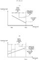
Fig. 2 is schematic graphs of a relationship between the frequency of voltage output from theinverter 107 and temperature measured by thetemperature sensor 108, and a relationship between pressure discharged from the compressor and the temperature measured by thetemperature sensor 108 in the first embodiment.Fig. 2(1) shows a relationship between a frequency f and a temperature T, andFig. 2(2) shows a relationship between a pressure P and the temperature T. - As shown in
Fig. 2(1) , the frequency f changes between alowest frequency 201 and ahighest frequency 202 such that pressure is constant when the air amount of compressed air to be discharged is changed. When the frequency f decreases, the rotation speed of the cooling fan rotating on theshaft 103 similar to the compressor decreases, so that the air amount of cooling air decreases and accordingly, the temperature T of the compressor rises. The relationship changes as indicated by 203, and when the frequency f decreases, the temperature T of the compressor rises. - In addition, the relationship between the pressure P and the temperature T is as shown in
Fig. 2(2) , and the pressure changes from 0 MPa to ahighest pressure 206. When the pressure P increases, the temperature of thefixed scroll 105 rises with a rise in temperature of the compressed air, and the temperature T also rises. A product in the related art controls a threshold value with respect to the frequency f and the pressure T to a fixed value as indicated by 204. For this reason, there is a possibility that even when the frequency f increases or the pressure decreases, the product in the related art cannot detect abnormality until the temperature rises to 204, and there is a delay in dealing with abnormality occurring in the compressor. For this reason, the threshold value is made to depend on the frequency and the pressure as indicated by 205 and 208, and control is performed such that abnormality can be detected early. - A method for determining a threshold value T(f) corresponding to the frequency f is represented by equation (1) where the threshold value is a value obtained by adding a constant value to a normal temperature To(f), equation (2) where the threshold value is expressed as a function of the frequency f using arbitrary coefficients k and β, or the like, and more generally, may be represented by equation (3).


- A method for determining a threshold value T(P) corresponding to the pressure P is represented by equation (4) where the threshold value is a value obtained by adding a constant value to a normal temperature To(P), equation (5) where the threshold value is expressed as a function of the pressure P using arbitrary coefficients m and β, or the like, and more generally, may be represented by equation (6).


- In
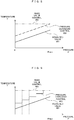
Fig. 3 , the methods for determining the threshold values shown inFig. 2 are simplified. In methods for determining threshold values shown inFig. 3 , the frequency and the pressure each are divided into ranges, and the threshold values each are changed to constant threshold values in a stepwise manner for each range as indicated by 303 and 305.Threshold values 303 and 305 are larger than the values ofnormal temperatures 303 and 304. When the range is divided, the size of the range may be divided according to a portion even in a certain range. In addition, the number of divisions is also arbitrary. - In
Fig. 4 , the threshold values of the temperature are mapped with respect to the pressure and the frequency. When the threshold value is actually determined, the threshold value is required to be determined based on both the pressure and the frequency, so that the threshold value within the range of each threshold value and frequency is used as a value for determining temperature abnormality. When the frequency or the pressure changes, the threshold value is accordingly changed. For example, when an operation is performed at a frequency of 260 Hz and a pressure of 0.5 MPa, the threshold value is 40 K. When the frequency does not change from this point and the pressure rises to 0.65 MPa, the threshold value is changed to 45 K and a determination is performed. Here, the unit Kelvin (K) is a measured temperature which is relative to the ambient temperature (air temperature) of the compressor, and in the case of 30 K, the measured temperature is 30°C higher than the ambient temperature. -
Fig. 5 shows a relationship between a temperature of thecompressor 502 when temperature is measured in a portion of 108 inFig. 1 , adischarge temperature 501, and an operating state of thecompressor 503. In a period from t1 to t2 inFig. 4 for which the compressor is stopped, since gas is not compressed, thedischarge temperature 501 decreases, but the temperature of thecompressor 502 rises due to heat transfer from the highest temperature location inside the compressor since the coolingfan 106 is stopped. When an operation starts at t2, the discharge temperature rises again and the temperature of the compressor is cooled by the cooling fan, so that the temperature decreases. However, it takes up to t3 for the temperature to decrease until the operation is continuously performed. Namely, it is normal that the temperature in a period from t1 to t3 is higher than that in a steady state, and when a determination on temperature abnormality is performed in the range, the temperature may exceed the threshold value. For this reason, in the present embodiment, a determination is not performed in the range from t1 to t3. -
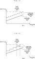
Fig. 6 shows a graph of time change of a relationship between atemperature rise value 605 of the compressor and athreshold value 604 when apressure 601 and afrequency 602 change. The amount of a change in threshold value is adjusted depending on whether the threshold value is increased or decreased, so that the possibility of erroneous detection can be reduced. - In this control, when the threshold value is increased as at time t1, since the threshold value is a threshold value of 45 K at time t1 as indicated by a
threshold value increase 606, the threshold value is immediately increased to 45 K. On the other hand, when the threshold value is decreased as at time t2, control is performed such that as indicated bythreshold value decrease 607, the threshold value is not immediately decreased to a threshold value of 50 K at time t2, but the threshold value is decreased over time in a stepwise manner, linearly, or non-linearly. The reason is that since it takes time for the temperature of the compressor to decrease, when the threshold value is immediately decreased, there is a possibility of detecting abnormality of the compressor even though there is no abnormality. -
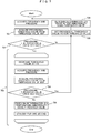
Fig. 7 is a flowchart to determine temperature abnormality of the compressor. After the frequency and the pressure are acquired, atstep 701, a provisional threshold value is acquired from the threshold value map shown inFig. 4 . When the provisional threshold value is larger than a current threshold value atstep 702, atemperature abnormality determination 706 is performed with the provisional threshold value set to anew threshold value 705. When the provisional threshold value is smaller than the threshold value atstep 702, adetermination 706 is performed while the threshold value is decreased by 1 K at certain time intervals up to the provisional threshold value as atstep 703. If a pressure rise or a frequency decrease occurs in the middle ofstep 703 and the provisional threshold value is larger than the threshold value in the determination atstep 704, the process of decreasing the threshold value by 1 K at the certain time intervals up to the provisional threshold value is stopped, and a determination on temperature abnormality is performed with the provisional threshold value set to the threshold value. - Since the threshold value is not set to a fixed value and is changed according to the pressure and the frequency as described above, the accuracy of detecting a temperature rise caused by wear of the compressor is further improved, and maintenance can be performed before damage occurs due to the wear of the compressor.
- In
Fig. 7 , the method for using the threshold value map to acquire the threshold value is adopted; however, when a method for acquiring the threshold value by calculation is adopted, the provisional threshold value is calculated atstep 701 and a third step ofstep 703 of acquiring the provisional threshold value, so that the same control can be performed. - Incidentally, in the present embodiment, the inverter machine has been described as a target; however, a compressor which is subjected to constant speed control without using the inverter may be used, and in that case, only the threshold value is changed for a change in pressure, so that similarly, a determination can be performed with high detection accuracy.
- In addition, in the present embodiment, an example where the threshold value is changed according to the pressure and the frequency has been described; however, the threshold value can be changed according to only the pressure or only the frequency.
-
Fig. 8 shows the discharge temperature of the compressor when pressure changes, the discharge temperature being measured in a discharge port for the compressed gas by thetemperature sensor 109 inFig. 1 . The discharge temperature depends on the pressure, and when the pressure increases, the discharge temperature also increases. A method for determining a threshold value T'(P) of 802 corresponding to the pressure P is represented by equation (7) where the threshold value is a value obtained by adding a constant value to a normal temperature To'(P) of 801, equation (8) where the threshold value is expressed as a function of the pressure P using the arbitrary coefficients m and β, or the like, and more generally, may be represented by equation (9).


- In
Fig. 9 , the method for determining the threshold value shown inFig. 8 is simplified similar toFig. 3 . In the method for determining the threshold value shown inFig. 9 , the pressure is divided into ranges, and the threshold value is set to a constant threshold value for each range as indicated by 902. A threshold value 902 is larger than the value of a normal temperature 901. When the range is divided, the size of the range may be divided according to a portion even in a certain range. In addition, the number of divisions is also arbitrary. -
Fig. 10 is a flowchart to determine abnormality of the compressor according to the discharge temperature. Since the discharge temperature is obtained by directly measuring the temperature of compressed air, the discharge temperature reacts more sensitively to a change in pressure than when heat transfer is measured in the first embodiment. For this reason, the flow is more simplified than measuring the temperature of the compressor, and is a flow in which the pressure is acquired atstep 1001, the threshold value is determined from a threshold value map atstep 1002, and a determination on temperature abnormality is performed atstep 1003. -
Fig. 11 shows a method by measuring a current value when pressure changes. Since the current value input into the motor is power used to compress gas, when the pressure increases, the current value also increases. Therefore, when a current value I acquired from the ammeter (not shown) provided in theinverter 107 exceeds a threshold value I(P), thecontrol unit 110 - A method for determining a threshold value I(P) of 1102 corresponding to the pressure P is represented by equation (10) where the threshold value is a value obtained by adding a constant value to a normal current value Io(P) of 1101, equation (11) where the threshold value is expressed as a function of the pressure P using the arbitrary coefficients m and β, or the like, and more generally, may be represented by equation (12).


- In
Fig. 12 , the method for determining the threshold value shown inFig. 11 is simplified similar toFig. 3 . In the method for determining the threshold value shown inFig. 12 , the pressure is divided into ranges, and the threshold value is set to a constant threshold value for each range as indicated by 1202. Athreshold value 1202 is larger than the value of a normal temperature 1201. When the range is divided, the size of the range may be divided according to a portion even in a certain range. In addition, the number of divisions is also arbitrary. -
Fig. 13 is a flowchart to determine abnormality of the compressor according to the current value. Since the current value is directly affected by compressed air, the current value reacts more sensitively to a change in pressure than when heat transfer is measured in the first embodiment. For this reason, the flow is more simplified than measuring the temperature of the compressor, and is a flow in which the pressure is acquired atstep 1301, the threshold value is determined from a threshold value map atstep 1302, and a determination on abnormality is performed atstep 1303. -
Fig. 14 shows a method by measuring an input power value when pressure changes. The input power value is a value dependent on the pressure similar to the third embodiment, and when the pressure increases, the input value also increases. A method for determining a threshold value W(P) of 1402 corresponding to the pressure P is represented by equation (13) where the threshold value is a value obtained by adding a constant value to a normal input value W(P) of 1401, equation (14) where the threshold value is expressed as a function of the pressure P using the arbitrary coefficients m and β, or the like, and more generally, may be represented by equation (15) .


- In
Fig. 15 , the method for determining the threshold value shown inFig. 14 is simplified similar toFig. 3 . In the method for determining the threshold value shown inFig. 15 , the pressure is divided into ranges, and the threshold value is set to a constant threshold value for each range as indicated by 1502. Athreshold value 1502 is larger than the value of a normal temperature 1501. When the range is divided, the size of the range may be divided according to a portion even in a certain range. In addition, the number of divisions is also arbitrary. -
Fig. 16 is a flowchart to determine abnormality of the compressor according to the input value. Since the input value is obtained by directly measuring compressed air, the input value reacts sensitively to a change in pressure. For this reason, the flow is more simplified than measuring the temperature of the compressor, and is a flow in which the pressure is acquired atstep 1601, the threshold value is determined from a threshold value map atstep 1602, and a determination on abnormality is performed atstep 1603. - Incidentally, equations (3), (6), (9), (12), and (15) use an equation such as a quadratic function and an exponential function according to a distribution of the normal temperature, current, or power, or a value that matches the tendency of equations (3), (6), (9), (12), and (15) stored in a storage unit can be also used.
- Incidentally, in the present invention, a scroll compressor has been described as an example; however, the present invention is not limited to the scroll machine, and can be adopted in a fluid machine such as a twin or single screw type, a reciprocating type, or a turbo type as long as the fluid machine includes a temperature sensor that measures the temperature of a fluid machine body or a discharge fluid, and a sensor that measures a current or a power input into a motor. In addition, the present invention can be also adopted in compressors such as a compressor that compresses a mixed gas such as air and a compressor that compresses a single gas such as nitrogen gas or oxygen gas. Further, the present invention can be adopted in a fluid machine such as a chiller or a pump including the same mechanism other than the compressor.
- In addition, the present invention is not limited to the above embodiments, and includes various modification examples. For example, the above embodiments have been described in detail to describe the present invention in an easy-to-understand manner, and the present invention is not necessarily limited to including all the configurations described. In addition, a part of the configuration of an embodiment can be replaced with the configuration of another embodiment, and the configuration of another embodiment can be added to the configuration of an embodiment. In addition, other configurations can also be added to, removed from, or replaced with a part of the configuration of each of the embodiments. It is needless to say that even when the temperature of the discharge fluid in the second embodiment, an input current to the motor in the third embodiment, or the power consumption of the motor in the fourth embodiment is used, similar to the first embodiment, control is performed such that a notification is not issued when the threshold value is exceeded during start of the fluid machine as described with reference to
Fig. 5 , or the threshold value can be changed based on the frequency of the output voltage of the inverter. -
- 103
- Shaft
- 104
- Orbiting scroll
- 105
- Fixed scroll
- 106
- Cooling fan
- 107
- Inverter
- 108
- Measurement position of temperature of compressor
- 109
- Measurement position of discharge temperature
Claims (15)
- A fluid machine comprising:a fluid machine body;a motor that drives the fluid machine body;a temperature sensor that measures a temperature of the fluid machine body; anda control unit that controls the fluid machine body,wherein the control unit changes a temperature threshold value based on at least one of a pressure of a fluid discharged by the fluid machine body and a frequency of a voltage input into the motor, and issues a notification when the temperature of the compressor body measured by the temperature sensor exceeds the temperature threshold value.
- The fluid machine according to claim 1,
wherein when the control unit changes the temperature threshold value based on the pressure of the fluid discharged by the fluid machine body, the temperature threshold value when the pressure of the fluid is high is larger than or equal to the temperature threshold value when the pressure of the fluid is low. - The fluid machine according to claim 1,
wherein when the control unit changes the temperature threshold value based on the frequency of the voltage input into the motor, the temperature threshold value when the frequency of the voltage is high is less than or equal to the temperature threshold value when the frequency of the voltage is low. - The fluid machine according to claim 1,
wherein the control unit does not issue a notification when the temperature measured by the temperature sensor exceeds the temperature threshold value for a predetermined time from start of operation of the fluid machine body. - The fluid machine according to claim 1,
wherein the temperature of the fluid machine body measured by the temperature sensor is a temperature of a heat radiation fin that radiates heat generated in an operation chamber of the fluid machine body. - The fluid machine according to claim 1,
wherein the temperature of the fluid machine body measured by the temperature sensor is a temperature of a heat radiation fin that radiates heat generated in an operation chamber of the fluid machine. - The fluid machine according to claim 5,
wherein when the control unit changes the temperature threshold value from a first temperature threshold value to a second temperature threshold value lower than the first temperature threshold value, the control unit changes the temperature threshold value to a third temperature threshold value that is a temperature between the first temperature threshold value and the second temperature threshold value, and then changes the temperature threshold value to the second temperature threshold value. - A fluid machine comprising:a fluid machine body;a motor that drives the fluid machine body;an ammeter that measures a current input into the motor; anda control unit that controls the fluid machine body,wherein the control unit changes a current threshold value based on at least one of a pressure of a fluid discharged by the fluid machine body and a frequency of a voltage input into the motor, and issues a notification when the current measured by the ammeter exceeds the current threshold value.
- The fluid machine according to claim 8,
wherein when the control unit changes the current threshold value based on the pressure of the fluid discharged by the fluid machine body, the current threshold value when the pressure of the fluid is high is larger than or equal to the current threshold value when the pressure of the fluid is low. - The fluid machine according to claim 8,
wherein when the control unit changes the current threshold value based on the frequency of the voltage input into the motor, the current threshold value when the frequency of the voltage is high is less than or equal to the current threshold value when the frequency of the voltage is low. - The fluid machine according to claim 8,
wherein the control unit does not issue a notification when the current measured by the ammeter exceeds the current threshold value for a predetermined time from start of operation of the fluid machine body. - A fluid machine comprising:a fluid machine body;a motor that drives the fluid machine body;an ammeter that measures a current input into the motor; anda control unit that controls the fluid machine body,wherein the control unit changes a power threshold value based on at least one of a pressure of a fluid discharged by the fluid machine body and a frequency of a voltage input into the motor, and issues a notification when a power obtained from the current measured by the ammeter exceeds the power threshold value.
- The fluid machine according to claim 12,
wherein when the control unit changes the power threshold value based on the pressure of the fluid discharged by the fluid machine body, the power threshold value when the pressure of the fluid is high is larger than or equal to the power threshold value when the pressure of the fluid is low. - The fluid machine according to claim 12,
wherein when the control unit changes the power threshold value based on the frequency of the voltage input into the motor, the power threshold value when the frequency of the voltage is high is less than or equal to the power threshold value when the frequency of the voltage is low. - The fluid machine according to claim 12,
wherein the control unit does not issue a notification when the power obtained from the current measured by the ammeter exceeds the power threshold value for a predetermined time from start of operation of the fluid machine body.
Priority Applications (1)
| Application Number | Priority Date | Filing Date | Title |
|---|---|---|---|
| EP25180869.7A EP4603705A3 (en) | 2018-12-20 | 2019-11-28 | Fluid machine |
Applications Claiming Priority (2)
| Application Number | Priority Date | Filing Date | Title |
|---|---|---|---|
| JP2018237868A JP7236265B2 (en) | 2018-12-20 | 2018-12-20 | Fluid machinery |
| PCT/JP2019/046499 WO2020129564A1 (en) | 2018-12-20 | 2019-11-28 | Fluid machine |
Related Child Applications (2)
| Application Number | Title | Priority Date | Filing Date |
|---|---|---|---|
| EP25180869.7A Division-Into EP4603705A3 (en) | 2018-12-20 | 2019-11-28 | Fluid machine |
| EP25180869.7A Division EP4603705A3 (en) | 2018-12-20 | 2019-11-28 | Fluid machine |
Publications (3)
| Publication Number | Publication Date |
|---|---|
| EP3901461A1 true EP3901461A1 (en) | 2021-10-27 |
| EP3901461A4 EP3901461A4 (en) | 2023-04-05 |
| EP3901461B1 EP3901461B1 (en) | 2025-07-09 |
Family
ID=71101447
Family Applications (2)
| Application Number | Title | Priority Date | Filing Date |
|---|---|---|---|
| EP25180869.7A Pending EP4603705A3 (en) | 2018-12-20 | 2019-11-28 | Fluid machine |
| EP19898545.9A Active EP3901461B1 (en) | 2018-12-20 | 2019-11-28 | Fluid machine |
Family Applications Before (1)
| Application Number | Title | Priority Date | Filing Date |
|---|---|---|---|
| EP25180869.7A Pending EP4603705A3 (en) | 2018-12-20 | 2019-11-28 | Fluid machine |
Country Status (5)
| Country | Link |
|---|---|
| US (1) | US11976648B2 (en) |
| EP (2) | EP4603705A3 (en) |
| JP (1) | JP7236265B2 (en) |
| CN (1) | CN112469900B (en) |
| WO (1) | WO2020129564A1 (en) |
Families Citing this family (1)
| Publication number | Priority date | Publication date | Assignee | Title |
|---|---|---|---|---|
| JP7794557B2 (en) * | 2020-06-10 | 2026-01-06 | Zacros株式会社 | Sealing film, electrode lead wire member and battery |
Family Cites Families (27)
| Publication number | Priority date | Publication date | Assignee | Title |
|---|---|---|---|---|
| US3877842A (en) * | 1970-01-21 | 1975-04-15 | Itt | Air pumps |
| US4672920A (en) * | 1984-12-10 | 1987-06-16 | Duprez Wayne R | Pressure compensated temperature switch unit for protection of an internal combustion engine |
| US4743176A (en) * | 1986-06-18 | 1988-05-10 | Tecumseh Products Company | Gas flow system for a compressor |
| JPH0460360A (en) * | 1990-06-28 | 1992-02-26 | Toshiba Corp | Apparatus for air conditioning |
| JPH07122431B2 (en) * | 1990-08-27 | 1995-12-25 | 三菱電機株式会社 | Air conditioner protector |
| US5542395A (en) * | 1993-11-15 | 1996-08-06 | Walbro Corporation | Temperature-compensated engine fuel delivery |
| JPH06213171A (en) * | 1992-11-25 | 1994-08-02 | Daikin Ind Ltd | Lock detecting device for compressor of inverter-driven air-conditioner |
| US5627417A (en) * | 1993-11-04 | 1997-05-06 | Diversified Electronics, Inc. | Compressor minimum off-time switch for series connection with delay-on-break feature |
| US5653125A (en) * | 1995-01-26 | 1997-08-05 | Boyanich; Joseph E. | Compressor with isolated motor windings |
| US6036449A (en) * | 1998-03-24 | 2000-03-14 | Cummins Engine Company, Inc. | Air compressor control |
| GB0014003D0 (en) * | 2000-06-09 | 2000-08-02 | Drum Int Ltd | Control devices |
| DE10120206A1 (en) * | 2001-04-24 | 2002-10-31 | Wabco Gmbh & Co Ohg | Method for controlling a compressor |
| JP4243604B2 (en) * | 2005-09-27 | 2009-03-25 | パナソニック株式会社 | Electric compressor drive device |
| WO2007076060A2 (en) * | 2005-12-21 | 2007-07-05 | Seth Smith | Monitoring system |
| JP2007205206A (en) * | 2006-01-31 | 2007-08-16 | Hitachi Ltd | Scroll type fluid machine |
| JP4851259B2 (en) | 2006-07-31 | 2012-01-11 | 株式会社日立産機システム | Compressor |
| US8459053B2 (en) * | 2007-10-08 | 2013-06-11 | Emerson Climate Technologies, Inc. | Variable speed compressor protection system and method |
| DE102007062313B4 (en) * | 2007-12-21 | 2018-07-26 | Continental Teves Ag & Co. Ohg | Method, device and use of the device for controlling a compressor |
| JP2009198139A (en) * | 2008-02-25 | 2009-09-03 | Panasonic Corp | Brushless motor driving device for compressor of air conditioner |
| DE102010016131B4 (en) * | 2010-03-25 | 2021-09-16 | Continental Teves Ag & Co. Ohg | Method for controlling a compressor |
| US8845301B2 (en) * | 2011-06-29 | 2014-09-30 | Ford Global Technologies, Llc | Compressor control method |
| JP5871157B2 (en) * | 2011-10-03 | 2016-03-01 | 株式会社Ihi | Method for preventing surging of centrifugal compression equipment |
| US8668042B2 (en) * | 2011-11-29 | 2014-03-11 | Caterpillar Inc. | System and method for controlling hydraulic system based on temperature |
| JP5975016B2 (en) * | 2013-12-05 | 2016-08-23 | 株式会社豊田自動織機 | Electric compressor |
| JP5975017B2 (en) * | 2013-12-05 | 2016-08-23 | 株式会社豊田自動織機 | Electric compressor |
| EP3225845B1 (en) * | 2014-11-27 | 2020-04-29 | Hitachi Industrial Equipment Systems Co., Ltd. | Compressor |
| CN107990497B (en) * | 2017-11-15 | 2019-11-12 | 广东美的制冷设备有限公司 | Operation control method, device, compressor and computer readable storage medium |
-
2018
- 2018-12-20 JP JP2018237868A patent/JP7236265B2/en active Active
-
2019
- 2019-11-28 US US17/269,101 patent/US11976648B2/en active Active
- 2019-11-28 CN CN201980048760.0A patent/CN112469900B/en active Active
- 2019-11-28 EP EP25180869.7A patent/EP4603705A3/en active Pending
- 2019-11-28 EP EP19898545.9A patent/EP3901461B1/en active Active
- 2019-11-28 WO PCT/JP2019/046499 patent/WO2020129564A1/en not_active Ceased
Also Published As
| Publication number | Publication date |
|---|---|
| EP3901461B1 (en) | 2025-07-09 |
| JP2020101093A (en) | 2020-07-02 |
| US20210310479A1 (en) | 2021-10-07 |
| CN112469900B (en) | 2022-11-15 |
| EP4603705A3 (en) | 2025-11-19 |
| JP7236265B2 (en) | 2023-03-09 |
| US11976648B2 (en) | 2024-05-07 |
| CN112469900A (en) | 2021-03-09 |
| EP3901461A4 (en) | 2023-04-05 |
| WO2020129564A1 (en) | 2020-06-25 |
| EP4603705A2 (en) | 2025-08-20 |
Similar Documents
| Publication | Publication Date | Title |
|---|---|---|
| EP2198165B1 (en) | Variable speed compressor protection system and method | |
| US11761443B2 (en) | Compressor and monitoring system | |
| CN100380103C (en) | Life prediction method of manufacturing equipment and rotating machine | |
| JP6081057B2 (en) | Method and system for monitoring compressor health | |
| EP3129719B1 (en) | Hvac systems and controls | |
| US20110188994A1 (en) | Method and system for determining gas turbine tip clearance | |
| EP3225845B1 (en) | Compressor | |
| CN114341495A (en) | Compressor, monitoring system and monitoring method of compressor | |
| EP3901461B1 (en) | Fluid machine | |
| US12146481B2 (en) | Gas compressor | |
| CN117432647A (en) | High-power high-pressure ratio centrifugal compressor performance test system and test method thereof | |
| JP6592129B2 (en) | Compressor | |
| US20220252065A1 (en) | Fluid Machine Device | |
| JP2003254253A (en) | Compressor and maintenance method therefor | |
| CN111434921A (en) | Compressor fault diagnosis device, system and method and compressor equipment | |
| EP3643979A1 (en) | Refrigeration cycle device | |
| Petrescu et al. | Experimental Analysis of Twin Screw Compressor's Energetic Efficiency Depending on Volume Ratio | |
| KR100315959B1 (en) | Performance tester of two-stage centrifugal compressor | |
| CN120092144A (en) | Stuffing box with degradation monitoring | |
| JP4374634B2 (en) | Surging prediction device for turbo compressor | |
| JP7798905B2 (en) | Gas compressor | |
| CN110100137A (en) | Vortex unloading detecting system | |
| CN115111163A (en) | Compressor protection module and protection method | |
| EP4596887A1 (en) | Control device and program | |
| CN121298303B (en) | Double-working-condition refrigerator performance testing method and device and related equipment |
Legal Events
| Date | Code | Title | Description |
|---|---|---|---|
| STAA | Information on the status of an ep patent application or granted ep patent |
Free format text: STATUS: THE INTERNATIONAL PUBLICATION HAS BEEN MADE |
|
| PUAI | Public reference made under article 153(3) epc to a published international application that has entered the european phase |
Free format text: ORIGINAL CODE: 0009012 |
|
| STAA | Information on the status of an ep patent application or granted ep patent |
Free format text: STATUS: REQUEST FOR EXAMINATION WAS MADE |
|
| 17P | Request for examination filed |
Effective date: 20210720 |
|
| AK | Designated contracting states |
Kind code of ref document: A1 Designated state(s): AL AT BE BG CH CY CZ DE DK EE ES FI FR GB GR HR HU IE IS IT LI LT LU LV MC MK MT NL NO PL PT RO RS SE SI SK SM TR |
|
| DAV | Request for validation of the european patent (deleted) | ||
| DAX | Request for extension of the european patent (deleted) | ||
| RIC1 | Information provided on ipc code assigned before grant |
Ipc: F04C 28/28 20060101ALI20221124BHEP Ipc: F04C 18/02 20060101ALI20221124BHEP Ipc: F04B 49/08 20060101ALI20221124BHEP Ipc: F04B 49/06 20060101ALI20221124BHEP Ipc: F04B 35/04 20060101ALI20221124BHEP Ipc: F04B 49/10 20060101AFI20221124BHEP |
|
| A4 | Supplementary search report drawn up and despatched |
Effective date: 20230303 |
|
| RIC1 | Information provided on ipc code assigned before grant |
Ipc: F04C 28/28 20060101ALI20230227BHEP Ipc: F04C 18/02 20060101ALI20230227BHEP Ipc: F04B 49/08 20060101ALI20230227BHEP Ipc: F04B 49/06 20060101ALI20230227BHEP Ipc: F04B 35/04 20060101ALI20230227BHEP Ipc: F04B 49/10 20060101AFI20230227BHEP |
|
| GRAP | Despatch of communication of intention to grant a patent |
Free format text: ORIGINAL CODE: EPIDOSNIGR1 |
|
| STAA | Information on the status of an ep patent application or granted ep patent |
Free format text: STATUS: GRANT OF PATENT IS INTENDED |
|
| INTG | Intention to grant announced |
Effective date: 20241010 |
|
| GRAJ | Information related to disapproval of communication of intention to grant by the applicant or resumption of examination proceedings by the epo deleted |
Free format text: ORIGINAL CODE: EPIDOSDIGR1 |
|
| STAA | Information on the status of an ep patent application or granted ep patent |
Free format text: STATUS: REQUEST FOR EXAMINATION WAS MADE |
|
| INTC | Intention to grant announced (deleted) | ||
| GRAP | Despatch of communication of intention to grant a patent |
Free format text: ORIGINAL CODE: EPIDOSNIGR1 |
|
| STAA | Information on the status of an ep patent application or granted ep patent |
Free format text: STATUS: GRANT OF PATENT IS INTENDED |
|
| INTG | Intention to grant announced |
Effective date: 20250221 |
|
| GRAS | Grant fee paid |
Free format text: ORIGINAL CODE: EPIDOSNIGR3 |
|
| GRAA | (expected) grant |
Free format text: ORIGINAL CODE: 0009210 |
|
| STAA | Information on the status of an ep patent application or granted ep patent |
Free format text: STATUS: THE PATENT HAS BEEN GRANTED |
|
| AK | Designated contracting states |
Kind code of ref document: B1 Designated state(s): AL AT BE BG CH CY CZ DE DK EE ES FI FR GB GR HR HU IE IS IT LI LT LU LV MC MK MT NL NO PL PT RO RS SE SI SK SM TR |
|
| REG | Reference to a national code |
Ref country code: GB Ref legal event code: FG4D |
|
| REG | Reference to a national code |
Ref country code: CH Ref legal event code: EP |
|
| REG | Reference to a national code |
Ref country code: IE Ref legal event code: FG4D |
|
| REG | Reference to a national code |
Ref country code: DE Ref legal event code: R096 Ref document number: 602019072458 Country of ref document: DE |
|
| REG | Reference to a national code |
Ref country code: NL Ref legal event code: MP Effective date: 20250709 |
|
| PG25 | Lapsed in a contracting state [announced via postgrant information from national office to epo] |
Ref country code: PT Free format text: LAPSE BECAUSE OF FAILURE TO SUBMIT A TRANSLATION OF THE DESCRIPTION OR TO PAY THE FEE WITHIN THE PRESCRIBED TIME-LIMIT Effective date: 20251110 |
|
| PG25 | Lapsed in a contracting state [announced via postgrant information from national office to epo] |
Ref country code: NL Free format text: LAPSE BECAUSE OF FAILURE TO SUBMIT A TRANSLATION OF THE DESCRIPTION OR TO PAY THE FEE WITHIN THE PRESCRIBED TIME-LIMIT Effective date: 20250709 |
|
| REG | Reference to a national code |
Ref country code: AT Ref legal event code: MK05 Ref document number: 1812028 Country of ref document: AT Kind code of ref document: T Effective date: 20250709 |
|
| PG25 | Lapsed in a contracting state [announced via postgrant information from national office to epo] |
Ref country code: IS Free format text: LAPSE BECAUSE OF FAILURE TO SUBMIT A TRANSLATION OF THE DESCRIPTION OR TO PAY THE FEE WITHIN THE PRESCRIBED TIME-LIMIT Effective date: 20251109 |
|
| PGFP | Annual fee paid to national office [announced via postgrant information from national office to epo] |
Ref country code: DE Payment date: 20251130 Year of fee payment: 7 |
|
| PGFP | Annual fee paid to national office [announced via postgrant information from national office to epo] |
Ref country code: GB Payment date: 20251120 Year of fee payment: 7 |
|
| PG25 | Lapsed in a contracting state [announced via postgrant information from national office to epo] |
Ref country code: NO Free format text: LAPSE BECAUSE OF FAILURE TO SUBMIT A TRANSLATION OF THE DESCRIPTION OR TO PAY THE FEE WITHIN THE PRESCRIBED TIME-LIMIT Effective date: 20251009 |
|
| REG | Reference to a national code |
Ref country code: LT Ref legal event code: MG9D |
|
| PG25 | Lapsed in a contracting state [announced via postgrant information from national office to epo] |
Ref country code: AT Free format text: LAPSE BECAUSE OF FAILURE TO SUBMIT A TRANSLATION OF THE DESCRIPTION OR TO PAY THE FEE WITHIN THE PRESCRIBED TIME-LIMIT Effective date: 20250709 |
|
| PG25 | Lapsed in a contracting state [announced via postgrant information from national office to epo] |
Ref country code: FI Free format text: LAPSE BECAUSE OF FAILURE TO SUBMIT A TRANSLATION OF THE DESCRIPTION OR TO PAY THE FEE WITHIN THE PRESCRIBED TIME-LIMIT Effective date: 20250709 |
|
| PG25 | Lapsed in a contracting state [announced via postgrant information from national office to epo] |
Ref country code: HR Free format text: LAPSE BECAUSE OF FAILURE TO SUBMIT A TRANSLATION OF THE DESCRIPTION OR TO PAY THE FEE WITHIN THE PRESCRIBED TIME-LIMIT Effective date: 20250709 |
|
| PGFP | Annual fee paid to national office [announced via postgrant information from national office to epo] |
Ref country code: FR Payment date: 20251120 Year of fee payment: 7 |
|
| PG25 | Lapsed in a contracting state [announced via postgrant information from national office to epo] |
Ref country code: GR Free format text: LAPSE BECAUSE OF FAILURE TO SUBMIT A TRANSLATION OF THE DESCRIPTION OR TO PAY THE FEE WITHIN THE PRESCRIBED TIME-LIMIT Effective date: 20251010 |
|
| PGFP | Annual fee paid to national office [announced via postgrant information from national office to epo] |
Ref country code: BE Payment date: 20251118 Year of fee payment: 7 |
|
| PG25 | Lapsed in a contracting state [announced via postgrant information from national office to epo] |
Ref country code: SE Free format text: LAPSE BECAUSE OF FAILURE TO SUBMIT A TRANSLATION OF THE DESCRIPTION OR TO PAY THE FEE WITHIN THE PRESCRIBED TIME-LIMIT Effective date: 20250709 |
|
| PG25 | Lapsed in a contracting state [announced via postgrant information from national office to epo] |
Ref country code: LV Free format text: LAPSE BECAUSE OF FAILURE TO SUBMIT A TRANSLATION OF THE DESCRIPTION OR TO PAY THE FEE WITHIN THE PRESCRIBED TIME-LIMIT Effective date: 20250709 |
|
| PG25 | Lapsed in a contracting state [announced via postgrant information from national office to epo] |
Ref country code: PL Free format text: LAPSE BECAUSE OF FAILURE TO SUBMIT A TRANSLATION OF THE DESCRIPTION OR TO PAY THE FEE WITHIN THE PRESCRIBED TIME-LIMIT Effective date: 20250709 Ref country code: BG Free format text: LAPSE BECAUSE OF FAILURE TO SUBMIT A TRANSLATION OF THE DESCRIPTION OR TO PAY THE FEE WITHIN THE PRESCRIBED TIME-LIMIT Effective date: 20250709 |
|
| PG25 | Lapsed in a contracting state [announced via postgrant information from national office to epo] |
Ref country code: RS Free format text: LAPSE BECAUSE OF FAILURE TO SUBMIT A TRANSLATION OF THE DESCRIPTION OR TO PAY THE FEE WITHIN THE PRESCRIBED TIME-LIMIT Effective date: 20251009 |
|
| PG25 | Lapsed in a contracting state [announced via postgrant information from national office to epo] |
Ref country code: ES Free format text: LAPSE BECAUSE OF FAILURE TO SUBMIT A TRANSLATION OF THE DESCRIPTION OR TO PAY THE FEE WITHIN THE PRESCRIBED TIME-LIMIT Effective date: 20250709 |
|
| PG25 | Lapsed in a contracting state [announced via postgrant information from national office to epo] |
Ref country code: RO Free format text: LAPSE BECAUSE OF FAILURE TO SUBMIT A TRANSLATION OF THE DESCRIPTION OR TO PAY THE FEE WITHIN THE PRESCRIBED TIME-LIMIT Effective date: 20250709 |
|
| PG25 | Lapsed in a contracting state [announced via postgrant information from national office to epo] |
Ref country code: SM Free format text: LAPSE BECAUSE OF FAILURE TO SUBMIT A TRANSLATION OF THE DESCRIPTION OR TO PAY THE FEE WITHIN THE PRESCRIBED TIME-LIMIT Effective date: 20250709 |
|
| PG25 | Lapsed in a contracting state [announced via postgrant information from national office to epo] |
Ref country code: DK Free format text: LAPSE BECAUSE OF FAILURE TO SUBMIT A TRANSLATION OF THE DESCRIPTION OR TO PAY THE FEE WITHIN THE PRESCRIBED TIME-LIMIT Effective date: 20250709 |
|
| PG25 | Lapsed in a contracting state [announced via postgrant information from national office to epo] |
Ref country code: IT Free format text: LAPSE BECAUSE OF FAILURE TO SUBMIT A TRANSLATION OF THE DESCRIPTION OR TO PAY THE FEE WITHIN THE PRESCRIBED TIME-LIMIT Effective date: 20250709 |
|
| PG25 | Lapsed in a contracting state [announced via postgrant information from national office to epo] |
Ref country code: CZ Free format text: LAPSE BECAUSE OF FAILURE TO SUBMIT A TRANSLATION OF THE DESCRIPTION OR TO PAY THE FEE WITHIN THE PRESCRIBED TIME-LIMIT Effective date: 20250709 |
|
| PG25 | Lapsed in a contracting state [announced via postgrant information from national office to epo] |
Ref country code: EE Free format text: LAPSE BECAUSE OF FAILURE TO SUBMIT A TRANSLATION OF THE DESCRIPTION OR TO PAY THE FEE WITHIN THE PRESCRIBED TIME-LIMIT Effective date: 20250709 Ref country code: SK Free format text: LAPSE BECAUSE OF FAILURE TO SUBMIT A TRANSLATION OF THE DESCRIPTION OR TO PAY THE FEE WITHIN THE PRESCRIBED TIME-LIMIT Effective date: 20250709 |
|
| PLBE | No opposition filed within time limit |
Free format text: ORIGINAL CODE: 0009261 |
|
| STAA | Information on the status of an ep patent application or granted ep patent |
Free format text: STATUS: NO OPPOSITION FILED WITHIN TIME LIMIT |