EP3901413A2 - Blades having tip pockets - Google Patents
Blades having tip pockets Download PDFInfo
- Publication number
- EP3901413A2 EP3901413A2 EP21167073.2A EP21167073A EP3901413A2 EP 3901413 A2 EP3901413 A2 EP 3901413A2 EP 21167073 A EP21167073 A EP 21167073A EP 3901413 A2 EP3901413 A2 EP 3901413A2
- Authority
- EP
- European Patent Office
- Prior art keywords
- airfoil
- cavities
- mid
- rotor blade
- outboard
- Prior art date
- Legal status (The legal status is an assumption and is not a legal conclusion. Google has not performed a legal analysis and makes no representation as to the accuracy of the status listed.)
- Granted
Links
- 238000002485 combustion reaction Methods 0.000 claims abstract description 19
- 239000007787 solid Substances 0.000 claims abstract description 9
- 239000012530 fluid Substances 0.000 description 9
- 239000007789 gas Substances 0.000 description 8
- 238000013016 damping Methods 0.000 description 4
- 239000000446 fuel Substances 0.000 description 3
- 230000001965 increasing effect Effects 0.000 description 3
- 230000004044 response Effects 0.000 description 3
- 230000008901 benefit Effects 0.000 description 2
- 239000000567 combustion gas Substances 0.000 description 2
- 230000007423 decrease Effects 0.000 description 2
- 239000011343 solid material Substances 0.000 description 2
- 238000011144 upstream manufacturing Methods 0.000 description 2
- 230000004075 alteration Effects 0.000 description 1
- 230000009286 beneficial effect Effects 0.000 description 1
- 230000015556 catabolic process Effects 0.000 description 1
- 239000002826 coolant Substances 0.000 description 1
- 238000006731 degradation reaction Methods 0.000 description 1
- 230000005611 electricity Effects 0.000 description 1
- 230000002708 enhancing effect Effects 0.000 description 1
- 230000005284 excitation Effects 0.000 description 1
- 230000001939 inductive effect Effects 0.000 description 1
- 230000001788 irregular Effects 0.000 description 1
- 238000000034 method Methods 0.000 description 1
- 238000012986 modification Methods 0.000 description 1
- 230000004048 modification Effects 0.000 description 1
- 230000002093 peripheral effect Effects 0.000 description 1
- 238000010248 power generation Methods 0.000 description 1
- 230000009467 reduction Effects 0.000 description 1
Images


Classifications
-
- F—MECHANICAL ENGINEERING; LIGHTING; HEATING; WEAPONS; BLASTING
- F01—MACHINES OR ENGINES IN GENERAL; ENGINE PLANTS IN GENERAL; STEAM ENGINES
- F01D—NON-POSITIVE DISPLACEMENT MACHINES OR ENGINES, e.g. STEAM TURBINES
- F01D5/00—Blades; Blade-carrying members; Heating, heat-insulating, cooling or antivibration means on the blades or the members
- F01D5/12—Blades
- F01D5/22—Blade-to-blade connections, e.g. for damping vibrations
- F01D5/225—Blade-to-blade connections, e.g. for damping vibrations by shrouding
-
- F—MECHANICAL ENGINEERING; LIGHTING; HEATING; WEAPONS; BLASTING
- F01—MACHINES OR ENGINES IN GENERAL; ENGINE PLANTS IN GENERAL; STEAM ENGINES
- F01D—NON-POSITIVE DISPLACEMENT MACHINES OR ENGINES, e.g. STEAM TURBINES
- F01D5/00—Blades; Blade-carrying members; Heating, heat-insulating, cooling or antivibration means on the blades or the members
- F01D5/12—Blades
- F01D5/14—Form or construction
- F01D5/147—Construction, i.e. structural features, e.g. of weight-saving hollow blades
-
- F—MECHANICAL ENGINEERING; LIGHTING; HEATING; WEAPONS; BLASTING
- F01—MACHINES OR ENGINES IN GENERAL; ENGINE PLANTS IN GENERAL; STEAM ENGINES
- F01D—NON-POSITIVE DISPLACEMENT MACHINES OR ENGINES, e.g. STEAM TURBINES
- F01D5/00—Blades; Blade-carrying members; Heating, heat-insulating, cooling or antivibration means on the blades or the members
- F01D5/12—Blades
- F01D5/14—Form or construction
- F01D5/16—Form or construction for counteracting blade vibration
-
- F—MECHANICAL ENGINEERING; LIGHTING; HEATING; WEAPONS; BLASTING
- F01—MACHINES OR ENGINES IN GENERAL; ENGINE PLANTS IN GENERAL; STEAM ENGINES
- F01D—NON-POSITIVE DISPLACEMENT MACHINES OR ENGINES, e.g. STEAM TURBINES
- F01D5/00—Blades; Blade-carrying members; Heating, heat-insulating, cooling or antivibration means on the blades or the members
- F01D5/12—Blades
- F01D5/14—Form or construction
- F01D5/18—Hollow blades, i.e. blades with cooling or heating channels or cavities; Heating, heat-insulating or cooling means on blades
-
- F—MECHANICAL ENGINEERING; LIGHTING; HEATING; WEAPONS; BLASTING
- F01—MACHINES OR ENGINES IN GENERAL; ENGINE PLANTS IN GENERAL; STEAM ENGINES
- F01D—NON-POSITIVE DISPLACEMENT MACHINES OR ENGINES, e.g. STEAM TURBINES
- F01D5/00—Blades; Blade-carrying members; Heating, heat-insulating, cooling or antivibration means on the blades or the members
- F01D5/12—Blades
- F01D5/14—Form or construction
- F01D5/20—Specially-shaped blade tips to seal space between tips and stator
-
- F—MECHANICAL ENGINEERING; LIGHTING; HEATING; WEAPONS; BLASTING
- F05—INDEXING SCHEMES RELATING TO ENGINES OR PUMPS IN VARIOUS SUBCLASSES OF CLASSES F01-F04
- F05D—INDEXING SCHEME FOR ASPECTS RELATING TO NON-POSITIVE-DISPLACEMENT MACHINES OR ENGINES, GAS-TURBINES OR JET-PROPULSION PLANTS
- F05D2240/00—Components
- F05D2240/20—Rotors
- F05D2240/30—Characteristics of rotor blades, i.e. of any element transforming dynamic fluid energy to or from rotational energy and being attached to a rotor
- F05D2240/307—Characteristics of rotor blades, i.e. of any element transforming dynamic fluid energy to or from rotational energy and being attached to a rotor related to the tip of a rotor blade
-
- F—MECHANICAL ENGINEERING; LIGHTING; HEATING; WEAPONS; BLASTING
- F05—INDEXING SCHEMES RELATING TO ENGINES OR PUMPS IN VARIOUS SUBCLASSES OF CLASSES F01-F04
- F05D—INDEXING SCHEME FOR ASPECTS RELATING TO NON-POSITIVE-DISPLACEMENT MACHINES OR ENGINES, GAS-TURBINES OR JET-PROPULSION PLANTS
- F05D2260/00—Function
- F05D2260/30—Retaining components in desired mutual position
-
- F—MECHANICAL ENGINEERING; LIGHTING; HEATING; WEAPONS; BLASTING
- F05—INDEXING SCHEMES RELATING TO ENGINES OR PUMPS IN VARIOUS SUBCLASSES OF CLASSES F01-F04
- F05D—INDEXING SCHEME FOR ASPECTS RELATING TO NON-POSITIVE-DISPLACEMENT MACHINES OR ENGINES, GAS-TURBINES OR JET-PROPULSION PLANTS
- F05D2260/00—Function
- F05D2260/96—Preventing, counteracting or reducing vibration or noise
-
- Y—GENERAL TAGGING OF NEW TECHNOLOGICAL DEVELOPMENTS; GENERAL TAGGING OF CROSS-SECTIONAL TECHNOLOGIES SPANNING OVER SEVERAL SECTIONS OF THE IPC; TECHNICAL SUBJECTS COVERED BY FORMER USPC CROSS-REFERENCE ART COLLECTIONS [XRACs] AND DIGESTS
- Y02—TECHNOLOGIES OR APPLICATIONS FOR MITIGATION OR ADAPTATION AGAINST CLIMATE CHANGE
- Y02T—CLIMATE CHANGE MITIGATION TECHNOLOGIES RELATED TO TRANSPORTATION
- Y02T50/00—Aeronautics or air transport
- Y02T50/60—Efficient propulsion technologies, e.g. for aircraft
Definitions
- the present application relates generally to apparatus, methods and/or systems concerning the design and operation of turbine rotor blades. More specifically, but not by way of limitation, the present application relates to apparatus and systems pertaining to turbine blades and configurations of turbine blades having tip pockets.
- the present application describes a rotor blade for use in a turbine of a combustion turbine engine.
- the rotor blade comprises an airfoil.
- the airfoil including a concave pressure sidewall and a convex suction sidewall extending axially between corresponding leading and trailing edges and radially between the base and an outboard tip end.
- the rotor blade further including at least one mid-span shroud configured to engage a corresponding mid-span shroud on at least one neighboring rotor blade during operation.
- the airfoil further includes an inboard region between the at least one mid-span shroud and the base of the blade with an inboard direction of the airfoil toward the base; and an outboard region between the at least one mid-span shroud and the outward tip end of the blade with an outboard direction of the airfoil toward the outward tip end.
- the outboard region includes at least two cavities extending from the outboard tip end inboard of the airfoil toward the at least one mid-span shroud; and inboard of the at least one mid-span shroud, the inboard region is substantially solid.
- a combustion turbine engine that comprises a rotor blade including an airfoil including a concave pressure sidewall and a convex suction sidewall extending axially between corresponding leading and trailing edges and radially between the base and an outboard tip end.
- the rotor blade further including at least one mid-span shroud configured to engage a corresponding mid-span shroud on at least one neighboring rotor blade during operation.
- the airfoil further includes an inboard region between the at least one mid-span shroud and the base of the blade with an inboard direction of the airfoil toward the base; and an outboard region between the at least one mid-span shroud and the outward tip end of the blade with an outboard direction of the airfoil toward the outward tip end.
- the outboard region includes at least two cavities extending from the outboard tip end inboard of the airfoil toward the at least one mid-span shroud; and inboard of the at least one mid-span shroud, the inboard region is substantially solid.
- downstream and upstream are terms that indicate a direction relative to the flow of a fluid, such as the working fluid through the turbine engine or, for example, the flow of air through the combustor or coolant through one of the turbine's component systems.
- downstream corresponds to the direction of flow of the fluid
- upstream refers to the direction opposite to the flow.
- forward and aft refer to directions, with “forward” referring to the forward or compressor end of the engine, and “aft” referring to the aft or turbine end of the engine.
- radial refers to movement or position perpendicular to an axis. It is often required to describe parts that are at differing radial positions with regard to a center axis. In cases such as this, if a first component resides closer to the axis than a second component, it will be stated herein that the first component is “radially inward” or “inboard” of the second component.
- first component resides further from the axis than the second component, it may be stated herein that the first component is “radially outward” or “outboard” of the second component.
- axial refers to movement or position parallel to an axis.
- circumferential refers to movement or position around an axis. It will be appreciated that such terms may be applied in relation to the center axis of the turbine, or, when referring to components within a combustor, the center axis of the combustor.
- a combustion turbine engine In a combustion turbine engine, it is well known that air pressurized in a compressor is used to combust a fuel in a combustor to generate a flow of hot combustion gases, whereupon such gases flow downstream through one or more turbines so that energy can be extracted therefrom.
- rows of circumferentially spaced turbine rotor blades extend radially outwardly from a supporting rotor disc.
- Each blade typically includes a dovetail that permits assembly and disassembly of the blade in a corresponding dovetail slot in the rotor disc, as well as an airfoil that extends radially outwardly from the dovetail and interacts with the flow of the working fluid through the engine.
- the airfoil has a generally concave pressure side and generally convex suction side extending axially between corresponding leading and trailing edges and radially between a root and a tip. It will be understood that the blade tip is spaced closely to a radially outer stationary shroud for minimizing leakage therebetween of the combustion gases flowing downstream between the turbine blades.
- Shrouds at the tip of the airfoil or tip shrouds often are implemented on aft stages or rotor blades to provide damping and reduce the over-tip leakage of the working fluid.
- the damping function of the tip shrouds provides a significant performance benefit.
- taking full advantage of the damping function may be difficult considering the weight that the tip shroud adds to the assembly and the other criteria which include enduring thousands of hours of operation exposed to high temperatures and extreme mechanical loads.
- large tip shrouds are desirable because they seal the gas path more effectively and may provide significant connection between neighboring rotor blades, which may improve damping
- larger tip shrouds may increase load on the rotor blade.
- Output and efficiency of gas turbine engines improve as the size of the engine and, and more specifically, the amount of air able to pass through it increase.
- the size of the engine is limited by operable length of the turbine blades, with longer turbine rotor blades enabling enlargement of the flow path through the engine.
- Longer rotor blades though, incur increased mechanical loads, which place further demands on the blades and the rotor disc that holds them. Longer rotor blades may also decrease the natural vibrational frequencies of the blades during operation, which increases the vibratory response of the rotor blades. Additional vibratory load may place demands on the rotor blade, which may further shorten the life of the component and, in some cases, may cause vibratory loads.
- One way to address the vibratory load of longer rotor blades is through shrouds that connect adjacent rotor blades to each other.
- shrouds can be positioned near the middle radial portion of the airfoil. As used herein, such shrouds will be referred to as a "mid-span shroud(s)." At this lower (or more inboard) radius, the mass of the shroud causes a reduced level of stress to the rotor blade.
- this type of shroud leaves a portion of the airfoil of the rotor blade unrestrained or cantilevered which is the portion of the airfoil that extends outboard of the mid-span shroud. This cantilevered portion of the airfoil typically results in lower frequency vibration and increased vibratory loads.
- an overall weight of the outboard portion of the blade may be beneficial.
- the reduction should also desirably alter the frequency and mode shape of the blade. This alteration will enhance blade and turbine efficiency.
- Figures 1 through 3 show an illustrative combustion turbine engine in which embodiments of the present application may be used. It will be understood by those skill in the art that the present embodiments are not limited to this type of usage. As stated, the present embodiments may be used in combustion turbine engines, such as the engines used in power generation and airplanes, steam turbine engines, and other type of rotary engines.
- FIG. 1 is a schematic, non-limiting, representation of a combustion turbine engine 10.
- combustion turbine engines operate by extracting energy from a pressurized flow of hot gas produced by the combustion of a fuel in a stream of compressed air.
- combustion turbine engine 10 may be configured with an axial compressor 11 that is mechanically coupled by a common shaft or rotor to a downstream turbine section or turbine 12, and a combustor 13 positioned between compressor 11 and turbine 12.
- FIG 2 illustrates a view of an exemplary, non-limiting, multi-staged axial compressor 11 that may be used in the combustion turbine engine of Figure 1 .
- compressor 11 may include a plurality of stages. Each stage may include a row of compressor rotor blades 14 followed by a row of compressor stator nozzles 15.
- a first stage may include a row of compressor rotor blades 14, which rotate about a central shaft, followed by a row of compressor stator nozzles 15, which remain stationary during operation.
- the compressor stator nozzles 15 generally are circumferentially spaced one from the other and fixed about the axis of rotation.
- the compressor rotor blades 14 are circumferentially spaced and attached to the shaft.
- compressor rotor blades 14 When the shaft rotates during operation, compressor rotor blades 14 rotate with it. Compressor rotor blades 14 are configured such that, when spun about the shaft, they impart kinetic energy to the air or fluid flowing through compressor 11. Compressor 11 may have other stages beyond the stages that are illustrated in Figure 2 . Additional stages may include a plurality of circumferential spaced compressor rotor blades 14 followed by a plurality of circumferentially spaced compressor stator nozzles 15.
- FIG 3 illustrates a non-limiting, partial view of an exemplary turbine section or turbine 13 that may be used in the combustion turbine engine of Figure 1 .
- Turbine 13 also may include a plurality of stages. Three exemplary stages are illustrated, but this is merely exemplary and is non-limiting and not intended to restrict the embodiments in any manner. Accordingly, more or less stages may present in turbine 13.
- a first stage includes a plurality of turbine buckets or turbine rotor blades 16 (hereinafter “blades”), which rotate about the shaft during operation, and a plurality of nozzles or turbine stator blades 17 (hereinafter “nozzles”), which remain stationary during operation.
- Nozzles 17 generally are circumferentially spaced one from the other and fixed about the axis of rotation.
- Turbine rotor blades 16 may be mounted on a turbine wheel or disc (not shown) for rotation with the shaft (not shown).
- a second stage of turbine 13 also is illustrated. The second stage similarly includes a plurality of circumferentially spaced nozzles 17 followed by a plurality of circumferentially spaced turbine rotor blades 16, which are also mounted on a turbine wheel for rotation.
- a third stage also is illustrated, and similarly includes a plurality of nozzles 17 and rotor blades 16. It will be appreciated that nozzles 17 and turbine rotor blades 16 lie in the hot gas path of turbine 13. The direction of flow of the hot gases through the hot gas path is indicated by the arrow.
- Turbine 13 may have other stages beyond the stages that are illustrated in Figure 3 . Each additional stage may include a row of nozzles 17 followed by a row of turbine rotor blades 16.
- rotation of compressor rotor blades 14 within axial compressor 11 may compress a flow of air.
- energy may be released when the compressed air is mixed with a fuel and ignited.
- the resulting flow of hot gases from combustor 12, which may be referred to as the working fluid is then directed over turbine rotor blades 16, the flow of working fluid inducing the rotation of turbine rotor blades 16 and the shaft.
- energy of the flow of working fluid is transformed into mechanical energy of the rotating blades and, because of the connection between the rotor blades and the shaft, the shaft rotates.
- the mechanical energy of the shaft may then be used to drive the rotation of compressor rotor blades 14, such that the necessary supply of compressed air is produced, and also, for example, a generator to produce electricity.
- blades 16 include an airfoil 25.
- Blade 16 includes a root or base 121 at one end attachable to a rotor, and an outboard tip end 41 at an opposed tip end of the airfoil 25 from the base 121.
- Airfoil 25 includes at least one of and preferably a plurality mid-span shrouds 51. With reference to the mid-span shrouds 51, the airfoil 25 defines an inboard portion of the airfoil 25 between the mid-span shrouds 51 and the base 121 of the blade 16, with an "inboard" orientation or direction being toward the base 121 of the airfoil 25.
- airfoil 25 defines an outboard portion of the airfoil 25 between the mid-span shrouds 51 and the outboard tip end 41 of the blade 16, with an "outboard" orientation or direction being toward outboard tip end 41 of the airfoil 25.
- airfoil 25 has an inboard region 58, which is the portion of airfoil 25 that is radially inboard of at least one of a plurality mid-span shrouds 51.
- Airfoil 25 also has an outboard region 59, which is the portion of airfoil 25 that is radially outboard of mid-span shrouds 51.
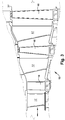
- Figures 4 and 5 are side views of a rotor blade 16 having a mid-span shrouds 51 and 51', and internal structure or configuration (which is shown via the dotted lines) according to embodiments of the present disclosure.
- Figures 6 and 7 illustrate the embodiment of the disclosure with focus on outboard region 59 of airfoil 25, as described hereinafter.
- inboard region 58 is solid or substantially solid, and outboard region 59 is hollow or “substantially" hollow.
- outboard region 59 includes a hollow region 64 that is any region or space within airfoil 25 that is hollow, such as cavities 61 and 66 formed therein (discussed below).
- inboard region includes a solid region 62 that is any region or space within airfoil 25 that is substantially solid material.
- outboard region 59 has a hollowness percentage of at least 40% and inboard region 58 has a solidness percentage of at least 60%.
- outboard region 59 may include at least two cavities 61 and 66 formed therein. As shown, the at least two cavities 61 and 66 are closed at their inboard end and in the outward orientation are open at outboard tip end 41 of airfoil 25. As illustrated in Figures 4-7 , cavities 61 and 66 that take up volume between pressure sidewall 26 and a suction sidewall 27 of airfoil 25. In accordance with non-limiting aspects of the disclosure, the at least two cavities 61 and 66 can be entirely in outboard region 59 above mid-span shrouds 51 and 51'.
- Cavities 61, 66 in outboard region 59 includes sidewalls 65 and 67, respectively and bottom walls 165 and 167, respectively.
- bottom walls 165 and 167 of cavities 61, 66 can be equi-distant into airfoil 25.
- cavities 61, 66 need not extend generally equi-distant, but can extend varying unequal distances into airfoil 25.
- bottom walls 165 and 167 of cavities 61, 66 do not need to be equidistant toward inboard region 58.
- bottom walls 165 and 167 can be generally orthogonal with the sidewalls 65 and 67, as per Figure 6 . While the Figures illustrate the bottom walls to be generally orthogonal to sidewalls, the scope of the embodiments do not restrict the bottoms walls to be generally orthogonal. As also illustrated in Figure 6 , a further non-limiting aspect of the embodiments can provide bottom walls angled from sidewalls 65 and 67, as indicated by dashed sidewalls 265 and 267.
- angles of the bottom walls 265 and 267 could be intersecting, angled extending from leading edge 20 to trailing edge 21 of airfoil 25, angled extending from trailing edge 21 to leading edge 20 of airfoil 25, angled from pressure side to suction side, angled from suction side to pressure side, and/or one bottom wall 265 and 267 angled extending from leading edge 20 to trailing edge 21 of airfoil 25 while the other bottom wall 265 and 267 is angled extending from trailing edge 21 to leading edge 20 of airfoil 25.
- non-limiting aspects of the disclosure's embodiments also include bottom walls that are equi-distant into airfoil 25 from outboard tip end 41 from the sidewalls 65 and 67, as indicated by dashed and dotted sidewalls 365 and 367 in Figure 7 .
- Other alternative arrangements of the bottom walls can incorporate orthogonal bottom walls with angled sections, curved bottom walls, and any combination of bottom walls in accordance to the non-limiting and illustrative description herein.
- the illustrated embodiments set forth two cavities 61 and 66. This configuration of two cavities is non-limiting of the embodiments and merely illustrative of the number of cavities that can be provided herein. More than two cavities 61 and 66 can be provided in airfoil 25.
- a stiffening rib 68 is formed in airfoil 25 at outboard tip end 41 between each cavity 61 and 66. Stiffening rib 68 provides enhanced structural integrity and overall strength to the airfoil, especially with the reduced mass in airfoil 25 at cavities 61 and 66 at outboard region 59. Of course, if more than two cavities are provided, more stiffening ribs 68 will be created, further enhancing integrity of the airfoil.
- cavities 61 and 66 at outboard region 59 extend a distance A from leading edge 20 towards trailing edge 21.
- distance A be no more than about 60% of airfoil 25, which should retain integrity and overall strength in airfoil 25 proximate trailing edge 21 with more solid mass compared to the cavities at area of airfoil 25 proximate leading edge 20. So, outboard region 59 has more solid material but still with a reduced weight, thereby reducing vibration and load.
- aspects of the embodiments could also include a distance A that is less than 60% of airfoil 25.
- each cavity 61 and 66 can have varying volumes. As noted above, any of the herein described bottom walls of cavities 65, 67 need not be equal. Also, noting the configuration of airfoil 25, each cavity will have a distinct periphery to confirm with the airfoil's shape and profile. For example and in a non-limiting example in Figure 6 , cavity 61 defines a first perimeter 161 of sidewall 65, and cavity 66 defines a second perimeter 166 of sidewall 65. These perimeters 161 and 166 are not necessarily equal, and thus an area of the respective cavities 61, 66 may not be equal even if the bottom walls extend to the same depth in hollow region 64.
- sidewalls of cavities 61 and 66 can vary along the depth of cavities 61 and 66.
- Figure 7 illustrates cavity 61 with two differing, non-limiting of the embodiments, sidewalls 465 and 466.
- Sidewall 465 is a roughened irregular sidewall.
- Sidewall 466 tapers increasing in width from outboard tip end 41 towards its bottom wall (omitted for ease of illustration).
- These sidewall structural arrangements are merely of multiple non-limiting sidewall structures, in whatever form that the end wall (as discussed above) takes. In other words, the geometry of cavities 61 and 66 can be different.
- the volume of cavities 61 and 66 can be unequal, as the depth of cavities 61, 66 into hollow region 64 can vary, the configurations, orientations, and angles of side and bottom wall can vary. Further peripheral area of each cavity can vary. All of these variations permit the volume of cavities 61 and 66 to not be necessarily equal. However, as can be envisioned, volumes of cavities 61 and 66 can be the same if above factors determining the cavity volume are selected to be equated in a volumetric determination.
- Blade 16 as embodied by the disclosure, provides an airfoil 25 with a reduced overall weight with cavities 61 and 66.
- the reduced overall weight should inhibit vibrations, and excitation forces on blade 16 during operation.
- Blade 16 including cavities 61 and 66 is capable of reducing vibrational forces and any loads therein over blade 16.
- a blade 16 with reduced weight provided by cavities 61 and 66 can reduce amplitudes of vibration forces (or natural frequency) so the mode shape or deflection at the natural frequency of such a blade is lower (compared to a blade without cavities 61 and 66). Thus, degradation of a blade 16 with cavities 61 and 66 may be reduced.
- Mid-span shrouds 51 and 51' may be defined broadly to include any shroud that is positioned inboard of an outboard tip end 41 of airfoil 25 and outboard of a base 121.
- the at least two cavities 61 and 66 should be entirely in outboard region 59 above mid-span shrouds 51 and 51'.
- Mid-span shrouds 51 and 51' also may be disposed within a range of radial positions on airfoil 25.
- the range of positions of mid-span shrouds 51 and 51' is defined between an inboard boundary of approximately 25% of the radial height of airfoil 25 and an outboard boundary of approximately 75% of the radial height of airfoil 25.
- the range of positions of a mid-span shrouds 51 and 51' is defined between an inboard boundary of approximately 33% of the radial height of airfoil 25 and an outboard boundary of approximately 66% of the radial height of airfoil 25.
- a mid-span shrouds 51 and 51' are positioned near the approximate radial center region of airfoil 25.
- vibratory response of turbine blades may be reduced to limit the damaging mechanical loads, which may enable lengthening of rotor blades so that greater engine efficiencies can be achieved. That is, the present disclosure teaches providing cavities 61 and 66 in turbine blades to limit the vibratory response of outboard region 59 that extends beyond the one or more mid-span shrouds 51 and 51', which thus increases the stiffness and decreases the portion of airfoil 25 outboard of mid-span shrouds 51 and 51'. In this manner, harmful vibrations can be avoided, thereby allowing for longer turbine blades.
Abstract
Description
- The present application relates generally to apparatus, methods and/or systems concerning the design and operation of turbine rotor blades. More specifically, but not by way of limitation, the present application relates to apparatus and systems pertaining to turbine blades and configurations of turbine blades having tip pockets.
- The present application describes a rotor blade for use in a turbine of a combustion turbine engine. The rotor blade comprises an airfoil. The airfoil including a concave pressure sidewall and a convex suction sidewall extending axially between corresponding leading and trailing edges and radially between the base and an outboard tip end. The rotor blade further including at least one mid-span shroud configured to engage a corresponding mid-span shroud on at least one neighboring rotor blade during operation. The airfoil further includes an inboard region between the at least one mid-span shroud and the base of the blade with an inboard direction of the airfoil toward the base; and an outboard region between the at least one mid-span shroud and the outward tip end of the blade with an outboard direction of the airfoil toward the outward tip end. The outboard region includes at least two cavities extending from the outboard tip end inboard of the airfoil toward the at least one mid-span shroud; and inboard of the at least one mid-span shroud, the inboard region is substantially solid.
- Another aspect of the application sets forth a combustion turbine engine that comprises a rotor blade including an airfoil including a concave pressure sidewall and a convex suction sidewall extending axially between corresponding leading and trailing edges and radially between the base and an outboard tip end. The rotor blade further including at least one mid-span shroud configured to engage a corresponding mid-span shroud on at least one neighboring rotor blade during operation. The airfoil further includes an inboard region between the at least one mid-span shroud and the base of the blade with an inboard direction of the airfoil toward the base; and an outboard region between the at least one mid-span shroud and the outward tip end of the blade with an outboard direction of the airfoil toward the outward tip end. The outboard region includes at least two cavities extending from the outboard tip end inboard of the airfoil toward the at least one mid-span shroud; and inboard of the at least one mid-span shroud, the inboard region is substantially solid..These and other features of the present application will become apparent upon review of the following detailed description of the preferred embodiments when taken in conjunction with the drawings and the appended claims.
- These and other features of this disclosure will be more completely understood and appreciated by careful study of the following more detailed description of exemplary embodiments of the disclosure taken in conjunction with the accompanying drawings, in which:
-
Figure 1 is a schematic representation of an exemplary combustion turbine engine in which embodiments of the present application may be used; -
Figure 2 is a sectional view of the compressor in the combustion turbine engine ofFigure 1 ; -
Figure 3 is a sectional view of the turbine in the combustion turbine engine ofFigure 1 ; -
Figure 4 is a schematic representation of an exemplary rotor blade having mid-span shrouds and internal configurations according to an embodiment of the present disclosure; -
Figure 5 is a side view of a blade with cavities and internal configurations according to an embodiment of the present disclosure; -
Figure 6 is a side view of a blade outboard region with cavities and internal configurations according to an embodiment of the present disclosure; and -
Figure 7 is partial sectional top view of a rotor blade outboard region with cavities, in accordance with embodiments of the present disclosure. - It is noted that the drawings of the disclosure are not necessarily to scale. The drawings are intended to depict only typical aspects of the disclosure, and therefore should not be considered as limiting the scope of the disclosure. In the drawings, like numbering represents like elements between the drawings.
- As an initial matter, it will be appreciated that to discuss the disclosure of the present application, it may be necessary to select terminology to refer to and describe particular components within a combustion turbine engine. Whenever possible, common industry terminology will be used and employed in a manner consistent with its accepted meaning. However, it is meant that any such terminology be given a broad meaning and not narrowly construed such that the meaning intended herein and the scope of the appended claims is unreasonably restricted. Those of ordinary skill in the art will appreciate that often a particular component may be referred to using several different terms. In addition, what may be described herein as being single part may include and be referenced in another context as consisting of multiple components, or, what may be described herein as including multiple components may be referred to elsewhere as a single part. As such, in understanding the scope of the present disclosure, attention should not only be paid to the terminology and description provided herein, but also to the structure, configuration, function, and/or usage of the component, particularly as provided in the appended claims.
- In addition, several descriptive terms may be used regularly herein, and it should prove helpful to define these terms at the onset of this section. Accordingly, these terms and their definitions, unless stated otherwise, are as follows. As used herein, "downstream" and "upstream" are terms that indicate a direction relative to the flow of a fluid, such as the working fluid through the turbine engine or, for example, the flow of air through the combustor or coolant through one of the turbine's component systems. As such, the term "downstream" corresponds to the direction of flow of the fluid, and the term "upstream" refers to the direction opposite to the flow. The terms "forward" and "aft", without any further specificity, refer to directions, with "forward" referring to the forward or compressor end of the engine, and "aft" referring to the aft or turbine end of the engine. The term "radial" refers to movement or position perpendicular to an axis. It is often required to describe parts that are at differing radial positions with regard to a center axis. In cases such as this, if a first component resides closer to the axis than a second component, it will be stated herein that the first component is "radially inward" or "inboard" of the second component. If, on the other hand, the first component resides further from the axis than the second component, it may be stated herein that the first component is "radially outward" or "outboard" of the second component. The term "axial" refers to movement or position parallel to an axis. Finally, the term "circumferential" refers to movement or position around an axis. It will be appreciated that such terms may be applied in relation to the center axis of the turbine, or, when referring to components within a combustor, the center axis of the combustor.
- In a combustion turbine engine, it is well known that air pressurized in a compressor is used to combust a fuel in a combustor to generate a flow of hot combustion gases, whereupon such gases flow downstream through one or more turbines so that energy can be extracted therefrom. In accordance with such a turbine, generally, rows of circumferentially spaced turbine rotor blades extend radially outwardly from a supporting rotor disc. Each blade typically includes a dovetail that permits assembly and disassembly of the blade in a corresponding dovetail slot in the rotor disc, as well as an airfoil that extends radially outwardly from the dovetail and interacts with the flow of the working fluid through the engine. The airfoil has a generally concave pressure side and generally convex suction side extending axially between corresponding leading and trailing edges and radially between a root and a tip. It will be understood that the blade tip is spaced closely to a radially outer stationary shroud for minimizing leakage therebetween of the combustion gases flowing downstream between the turbine blades.
- Shrouds at the tip of the airfoil or tip shrouds often are implemented on aft stages or rotor blades to provide damping and reduce the over-tip leakage of the working fluid. Given the length of the rotor blades in the aft stages, the damping function of the tip shrouds provides a significant performance benefit. However, taking full advantage of the damping function may be difficult considering the weight that the tip shroud adds to the assembly and the other criteria which include enduring thousands of hours of operation exposed to high temperatures and extreme mechanical loads. Thus, while large tip shrouds are desirable because they seal the gas path more effectively and may provide significant connection between neighboring rotor blades, which may improve damping, larger tip shrouds may increase load on the rotor blade.
- Output and efficiency of gas turbine engines improve as the size of the engine and, and more specifically, the amount of air able to pass through it increase. The size of the engine, however, is limited by operable length of the turbine blades, with longer turbine rotor blades enabling enlargement of the flow path through the engine. Longer rotor blades, though, incur increased mechanical loads, which place further demands on the blades and the rotor disc that holds them. Longer rotor blades may also decrease the natural vibrational frequencies of the blades during operation, which increases the vibratory response of the rotor blades. Additional vibratory load may place demands on the rotor blade, which may further shorten the life of the component and, in some cases, may cause vibratory loads. One way to address the vibratory load of longer rotor blades is through shrouds that connect adjacent rotor blades to each other.
- Another way to address this vibrational load is to position one or more shrouds lower on the airfoil of the rotor blade. That is, instead of adding the shroud to the tip of the rotor blade, shrouds can be positioned near the middle radial portion of the airfoil. As used herein, such shrouds will be referred to as a "mid-span shroud(s)." At this lower (or more inboard) radius, the mass of the shroud causes a reduced level of stress to the rotor blade. However, this type of shroud leaves a portion of the airfoil of the rotor blade unrestrained or cantilevered which is the portion of the airfoil that extends outboard of the mid-span shroud. This cantilevered portion of the airfoil typically results in lower frequency vibration and increased vibratory loads.
- To address the vibration and load concerns, reducing an overall weight of the outboard portion of the blade may be beneficial. The reduction should also desirably alter the frequency and mode shape of the blade. This alteration will enhance blade and turbine efficiency.
- By way of background, referring now to the Figures,
Figures 1 through 3 show an illustrative combustion turbine engine in which embodiments of the present application may be used. It will be understood by those skill in the art that the present embodiments are not limited to this type of usage. As stated, the present embodiments may be used in combustion turbine engines, such as the engines used in power generation and airplanes, steam turbine engines, and other type of rotary engines. -
Figure 1 is a schematic, non-limiting, representation of acombustion turbine engine 10. In general, combustion turbine engines operate by extracting energy from a pressurized flow of hot gas produced by the combustion of a fuel in a stream of compressed air. As illustrated inFigure 1 ,combustion turbine engine 10 may be configured with anaxial compressor 11 that is mechanically coupled by a common shaft or rotor to a downstream turbine section orturbine 12, and acombustor 13 positioned betweencompressor 11 andturbine 12. -
Figure 2 illustrates a view of an exemplary, non-limiting, multi-stagedaxial compressor 11 that may be used in the combustion turbine engine ofFigure 1 . As shown,compressor 11 may include a plurality of stages. Each stage may include a row ofcompressor rotor blades 14 followed by a row ofcompressor stator nozzles 15. Thus, a first stage may include a row ofcompressor rotor blades 14, which rotate about a central shaft, followed by a row ofcompressor stator nozzles 15, which remain stationary during operation. Thecompressor stator nozzles 15 generally are circumferentially spaced one from the other and fixed about the axis of rotation. Thecompressor rotor blades 14 are circumferentially spaced and attached to the shaft. When the shaft rotates during operation,compressor rotor blades 14 rotate with it.Compressor rotor blades 14 are configured such that, when spun about the shaft, they impart kinetic energy to the air or fluid flowing throughcompressor 11.Compressor 11 may have other stages beyond the stages that are illustrated inFigure 2 . Additional stages may include a plurality of circumferential spacedcompressor rotor blades 14 followed by a plurality of circumferentially spacedcompressor stator nozzles 15. -
Figure 3 illustrates a non-limiting, partial view of an exemplary turbine section orturbine 13 that may be used in the combustion turbine engine ofFigure 1 .Turbine 13 also may include a plurality of stages. Three exemplary stages are illustrated, but this is merely exemplary and is non-limiting and not intended to restrict the embodiments in any manner. Accordingly, more or less stages may present inturbine 13. A first stage includes a plurality of turbine buckets or turbine rotor blades 16 (hereinafter "blades"), which rotate about the shaft during operation, and a plurality of nozzles or turbine stator blades 17 (hereinafter "nozzles"), which remain stationary during operation.Nozzles 17 generally are circumferentially spaced one from the other and fixed about the axis of rotation.Turbine rotor blades 16 may be mounted on a turbine wheel or disc (not shown) for rotation with the shaft (not shown). A second stage ofturbine 13 also is illustrated. The second stage similarly includes a plurality of circumferentially spacednozzles 17 followed by a plurality of circumferentially spacedturbine rotor blades 16, which are also mounted on a turbine wheel for rotation. A third stage also is illustrated, and similarly includes a plurality ofnozzles 17 androtor blades 16. It will be appreciated thatnozzles 17 andturbine rotor blades 16 lie in the hot gas path ofturbine 13. The direction of flow of the hot gases through the hot gas path is indicated by the arrow.Turbine 13 may have other stages beyond the stages that are illustrated inFigure 3 . Each additional stage may include a row ofnozzles 17 followed by a row ofturbine rotor blades 16. - In a non-limiting description of use, rotation of
compressor rotor blades 14 withinaxial compressor 11 may compress a flow of air. Incombustor 12, energy may be released when the compressed air is mixed with a fuel and ignited. The resulting flow of hot gases fromcombustor 12, which may be referred to as the working fluid, is then directed overturbine rotor blades 16, the flow of working fluid inducing the rotation ofturbine rotor blades 16 and the shaft. Thereby, energy of the flow of working fluid is transformed into mechanical energy of the rotating blades and, because of the connection between the rotor blades and the shaft, the shaft rotates. The mechanical energy of the shaft may then be used to drive the rotation ofcompressor rotor blades 14, such that the necessary supply of compressed air is produced, and also, for example, a generator to produce electricity. - As used herein and as depicted on
Figures 4-7 ,blades 16 include anairfoil 25.Blade 16 includes a root or base 121 at one end attachable to a rotor, and anoutboard tip end 41 at an opposed tip end of theairfoil 25 from the base 121.Airfoil 25 includes at least one of and preferably a plurality mid-span shrouds 51. With reference to themid-span shrouds 51, theairfoil 25 defines an inboard portion of theairfoil 25 between themid-span shrouds 51 and the base 121 of theblade 16, with an "inboard" orientation or direction being toward the base 121 of theairfoil 25. Further, with reference tomid-span shrouds 51,airfoil 25 defines an outboard portion of theairfoil 25 between themid-span shrouds 51 and theoutboard tip end 41 of theblade 16, with an "outboard" orientation or direction being towardoutboard tip end 41 of theairfoil 25. - Also,
airfoil 25 has aninboard region 58, which is the portion ofairfoil 25 that is radially inboard of at least one of a plurality mid-span shrouds 51.Airfoil 25 also has anoutboard region 59, which is the portion ofairfoil 25 that is radially outboard of mid-span shrouds 51. - The embodiments will be described hereinafter with reference to a blade that includes mid-span shrouds, however, the features of the instant embodiments are not intended to be limited to a blade with mid-span shrouds. The features as disclosed herein are applicable to blades with or without mind-span shrouds.
-
Figures 4 and5 are side views of arotor blade 16 having amid-span shrouds 51 and 51', and internal structure or configuration (which is shown via the dotted lines) according to embodiments of the present disclosure.Figures 6 and 7 illustrate the embodiment of the disclosure with focus onoutboard region 59 ofairfoil 25, as described hereinafter. - According to embodiments of the present disclosure,
inboard region 58 is solid or substantially solid, andoutboard region 59 is hollow or "substantially" hollow. As used hereinoutboard region 59 includes ahollow region 64 that is any region or space withinairfoil 25 that is hollow, such ascavities solid region 62 that is any region or space withinairfoil 25 that is substantially solid material. In accordance with non-limiting aspects of the embodiments,outboard region 59 has a hollowness percentage of at least 40% andinboard region 58 has a solidness percentage of at least 60%. - According to embodiments of the present disclosure,
outboard region 59 may include at least twocavities cavities outboard tip end 41 ofairfoil 25. As illustrated inFigures 4-7 ,cavities airfoil 25. In accordance with non-limiting aspects of the disclosure, the at least twocavities outboard region 59 abovemid-span shrouds 51 and 51'. - While the Figures illustrate two cavities, the two
cavities -
Cavities outboard region 59 includes sidewalls 65 and 67, respectively andbottom walls bottom walls cavities airfoil 25. However,cavities airfoil 25. As illustrated in another non-limiting aspect inFigures 5 and6 ,bottom walls cavities inboard region 58. - Moreover, according to other non-limiting aspects of the embodiments,
bottom walls sidewalls Figure 6 . While the Figures illustrate the bottom walls to be generally orthogonal to sidewalls, the scope of the embodiments do not restrict the bottoms walls to be generally orthogonal. As also illustrated inFigure 6 , a further non-limiting aspect of the embodiments can provide bottom walls angled fromsidewalls sidewalls - Additionally, in other non-limiting aspects of the embodiments, the angles of the
bottom walls edge 20 to trailingedge 21 ofairfoil 25, angled extending from trailingedge 21 to leadingedge 20 ofairfoil 25, angled from pressure side to suction side, angled from suction side to pressure side, and/or onebottom wall edge 20 to trailingedge 21 ofairfoil 25 while the otherbottom wall edge 21 to leadingedge 20 ofairfoil 25. - Further, non-limiting aspects of the disclosure's embodiments also include bottom walls that are equi-distant into
airfoil 25 from outboard tip end 41 from thesidewalls sidewalls Figure 7 . Other alternative arrangements of the bottom walls can incorporate orthogonal bottom walls with angled sections, curved bottom walls, and any combination of bottom walls in accordance to the non-limiting and illustrative description herein. - The illustrated embodiments set forth two
cavities cavities airfoil 25. In the illustrated configuration ofFigure 7 , a stiffeningrib 68 is formed inairfoil 25 atoutboard tip end 41 between eachcavity rib 68 provides enhanced structural integrity and overall strength to the airfoil, especially with the reduced mass inairfoil 25 atcavities outboard region 59. Of course, if more than two cavities are provided,more stiffening ribs 68 will be created, further enhancing integrity of the airfoil. - As illustrated in
Figure 6 ,cavities outboard region 59 extend a distance A from leadingedge 20 towards trailingedge 21. Given the configuration ofairfoil 25, it is desirable that distance A be no more than about 60% ofairfoil 25, which should retain integrity and overall strength inairfoil 25proximate trailing edge 21 with more solid mass compared to the cavities at area ofairfoil 25 proximate leadingedge 20. So,outboard region 59 has more solid material but still with a reduced weight, thereby reducing vibration and load. Aspects of the embodiments could also include a distance A that is less than 60% ofairfoil 25. - In accordance with another facet of the embodiments, each
cavity cavities airfoil 25, each cavity will have a distinct periphery to confirm with the airfoil's shape and profile. For example and in a non-limiting example inFigure 6 ,cavity 61 defines afirst perimeter 161 ofsidewall 65, andcavity 66 defines asecond perimeter 166 ofsidewall 65. Theseperimeters respective cavities hollow region 64. - Also, sidewalls of
cavities cavities Figure 7 illustratescavity 61 with two differing, non-limiting of the embodiments, sidewalls 465 and 466.Sidewall 465 is a roughened irregular sidewall.Sidewall 466 tapers increasing in width fromoutboard tip end 41 towards its bottom wall (omitted for ease of illustration). These sidewall structural arrangements are merely of multiple non-limiting sidewall structures, in whatever form that the end wall (as discussed above) takes. In other words, the geometry ofcavities cavities cavities hollow region 64 can vary, the configurations, orientations, and angles of side and bottom wall can vary. Further peripheral area of each cavity can vary. All of these variations permit the volume ofcavities cavities -
Blade 16, as embodied by the disclosure, provides anairfoil 25 with a reduced overall weight withcavities blade 16 during operation.Blade 16 includingcavities blade 16. Moreover, ablade 16 with reduced weight provided bycavities cavities 61 and 66). Thus, degradation of ablade 16 withcavities -
Mid-span shrouds 51 and 51', according to the present disclosure, may be defined broadly to include any shroud that is positioned inboard of anoutboard tip end 41 ofairfoil 25 and outboard of a base 121. In accordance with non-limiting aspects of the disclosure, as noted above, the at least twocavities outboard region 59 abovemid-span shrouds 51 and 51'. -
Mid-span shrouds 51 and 51' according to present disclosure also may be disposed within a range of radial positions onairfoil 25. According to certain embodiments of the present disclosure, the range of positions ofmid-span shrouds 51 and 51' is defined between an inboard boundary of approximately 25% of the radial height ofairfoil 25 and an outboard boundary of approximately 75% of the radial height ofairfoil 25. According to other embodiments of the present disclosure, as may be defined by the appended claims, the range of positions of amid-span shrouds 51 and 51' is defined between an inboard boundary of approximately 33% of the radial height ofairfoil 25 and an outboard boundary of approximately 66% of the radial height ofairfoil 25. According to certain embodiments of the present disclosure, amid-span shrouds 51 and 51' are positioned near the approximate radial center region ofairfoil 25. - It will appreciated that, pursuant to the non-limiting and illustrative several embodiments discussed above, vibratory response of turbine blades may be reduced to limit the damaging mechanical loads, which may enable lengthening of rotor blades so that greater engine efficiencies can be achieved. That is, the present disclosure teaches providing
cavities outboard region 59 that extends beyond the one or moremid-span shrouds 51 and 51', which thus increases the stiffness and decreases the portion ofairfoil 25 outboard ofmid-span shrouds 51 and 51'. In this manner, harmful vibrations can be avoided, thereby allowing for longer turbine blades. - While the disclosure has been described in connection with what is presently considered to be the most practical and preferred embodiment, it is to be understood that the disclosure is not to be limited to the disclosed embodiment, but on the contrary, is intended to cover various modifications and equivalent arrangements included within the spirit and scope of the appended claims.
Claims (15)
- A rotor blade (16) for use in a turbine (13) of a combustion turbine engine (10), the rotor blade (16) comprising:
an airfoil (25), the airfoil (25) including a concave pressure sidewall (26) and a convex suction sidewall (27) extending axially between corresponding leading and trailing edges (20, 21) and radially between the base (121) and an outboard tip end (41), the rotor blade (16) further including:at least one mid-span shroud configured to engage a corresponding mid-span shroud on at least one neighboring rotor blade (16) during operation;the airfoil (25) further including an inboard region (58) between the at least one mid-span shroud and the base (121) of the blade (216) with an inboard direction of the airfoil (25) toward the base (121);the airfoil (25) further including an outboard region (59) between the at least one mid-span shroud and the outward tip end of the blade (216) with an outboard direction of the airfoil (25) toward the outward tip end;wherein:the outboard region (59) includes at least two cavities (61, 66) extending from the outboard tip end (41) inboard of the airfoil (25) toward the at least one mid-span shroud; andinboard of the at least one mid-span shroud, the inboard region (58) is substantially solid. - The rotor blade (16) of claim 1, wherein each of the at least two cavities (61, 66) are open at the outboard tip end (41) and closed at their inboard ends and include sidewalls (65, 465, 466) and bottom walls (265), the bottom walls (265) extending equi-distant into the airfoil (25).
- The rotor blade (16) of claim 1, wherein the at least two cavities (61, 66) include sidewalls (65, 465, 466) and bottom walls (265), the bottom walls (265) extending different distances into the airfoil (25).
- The rotor blade (16) of claim 1, wherein the at least two cavities (61, 66) include sidewalls (65, 465, 466) and bottom walls (265), the bottom walls (265) being orthogonal to the sidewalls (65, 465, 466).
- The rotor blade (16) of claim 1, wherein the at least two cavities (61, 66) include sidewalls (65, 465, 466) and bottom walls (265), the bottom walls (265) being non-orthogonal to the sidewalls (65, 465, 466).
- The rotor blade (16) of claim 1, wherein the at least two cavities (61, 66) include sidewalls (65, 465, 466) and bottom walls (265), each respective bottom walls (265) of the at least two cavities (61, 66) being at different angles respect to each other and the sidewalls (65, 465, 466).
- The rotor blade (16) of claim 1, wherein the at least two cavities (61, 66) include varying cross sections.
- The rotor blade (16) of claim 7, wherein the varying cross sections are formed by varying sidewalls (65, 465, 466) along a depth of the cavities (61, 66).
- The rotor blade (16) of claim 1, wherein the at least two cavities (61, 66) are open at the outboard tip end (41) and closed at their inboard ends.
- The rotor blade (16) of claim 1, wherein the at least two cavities (61, 66) include more than two cavities (61, 66) formed along a chord of the blade (216).
- The rotor blade (16) of claim 1, wherein, of at the outboard tip end (41), the at least two cavities (61, 66) extend up to 60% of the outboard tip end (41) from leading edge (20) to trailing edge (21).
- The rotor blade (16) of claim 1, wherein the at least two cavities (61, 66) define a stiffening rib (68) therebetween.
- The rotor blade (16) of claim 1, wherein the at least two cavities (61, 66) are entirely in the outboard region (59) above the at least one mid-span shroud.
- The rotor blade (16) of claim 1, wherein the outboard region (59) has hollowness percentage of at least 40% and wherein the inboard region (58) has a solidness percentage of at least 60%.
- A combustion turbine engine (10), the combustion turbine engine (10) comprising:
a rotor blade (16) including an airfoil (25), the airfoil (25) including a concave pressure sidewall (26) and a convex suction sidewall (27) extending axially between corresponding leading and trailing edges (21); a base (121) an outboard tip end (41), the rotor blade (16) further including:at least one mid-span shroud configured to engage a corresponding mid-span shroud on at least one neighboring rotor blade (16) during operation;the airfoil (25) further including an inboard region (58) between the at least one mid-span shroud and the base (121) of the blade (216) with an inboard direction of the airfoil (25) toward the base (121);the airfoil (25) further including an outboard region (59) between the at least one mid-span shroud and the outward tip end of the blade (216) with an outboard direction of the airfoil (25) toward the outward tip end;wherein:i. the outboard region (59) includes at least two cavities (61, 66) extending from the outboard tip end (41) inboard of the airfoil (25) toward the at least one mid-span shroud; and inboard of the at least one mid-span shroud, the inboard region (58) is substantially solid.
Applications Claiming Priority (1)
| Application Number | Priority Date | Filing Date | Title |
|---|---|---|---|
| US16/851,371 US11168569B1 (en) | 2020-04-17 | 2020-04-17 | Blades having tip pockets |
Publications (3)
| Publication Number | Publication Date |
|---|---|
| EP3901413A2 true EP3901413A2 (en) | 2021-10-27 |
| EP3901413A3 EP3901413A3 (en) | 2021-11-10 |
| EP3901413B1 EP3901413B1 (en) | 2023-05-31 |
Family
ID=75426402
Family Applications (1)
| Application Number | Title | Priority Date | Filing Date |
|---|---|---|---|
| EP21167073.2A Active EP3901413B1 (en) | 2020-04-17 | 2021-04-06 | Blades having tip pockets |
Country Status (5)
| Country | Link |
|---|---|
| US (1) | US11168569B1 (en) |
| EP (1) | EP3901413B1 (en) |
| JP (1) | JP2021173283A (en) |
| CN (1) | CN113530610A (en) |
| TW (1) | TW202204760A (en) |
Cited By (1)
| Publication number | Priority date | Publication date | Assignee | Title |
|---|---|---|---|---|
| EP3981952A1 (en) * | 2020-10-09 | 2022-04-13 | General Electric Company | Turbine bucket with dual part span shrouds and aerodynamic features |
Family Cites Families (13)
| Publication number | Priority date | Publication date | Assignee | Title |
|---|---|---|---|---|
| US1970435A (en) * | 1932-01-09 | 1934-08-14 | Baldwin Southwark Corp | Balanced turbine or pump runner and method of balancing |
| US4097192A (en) * | 1977-01-06 | 1978-06-27 | Curtiss-Wright Corporation | Turbine rotor and blade configuration |
| US4497613A (en) * | 1983-01-26 | 1985-02-05 | General Electric Company | Tapered core exit for gas turbine bucket |
| US6039542A (en) * | 1997-12-24 | 2000-03-21 | General Electric Company | Panel damped hybrid blade |
| DE10301755A1 (en) * | 2003-01-18 | 2004-07-29 | Rolls-Royce Deutschland Ltd & Co Kg | Fan blade for a gas turbine engine |
| US7001150B2 (en) * | 2003-10-16 | 2006-02-21 | Pratt & Whitney Canada Corp. | Hollow turbine blade stiffening |
| US7413409B2 (en) * | 2006-02-14 | 2008-08-19 | General Electric Company | Turbine airfoil with weight reduction plenum |
| US8684692B2 (en) * | 2010-02-05 | 2014-04-01 | Siemens Energy, Inc. | Cooled snubber structure for turbine blades |
| US20140255207A1 (en) | 2012-12-21 | 2014-09-11 | General Electric Company | Turbine rotor blades having mid-span shrouds |
| US9822647B2 (en) * | 2014-01-29 | 2017-11-21 | General Electric Company | High chord bucket with dual part span shrouds and curved dovetail |
| EP2942481B1 (en) * | 2014-05-07 | 2019-03-27 | Rolls-Royce Corporation | Rotor for a gas turbine engine |
| US10577940B2 (en) * | 2017-01-31 | 2020-03-03 | General Electric Company | Turbomachine rotor blade |
| US11111815B2 (en) * | 2018-10-16 | 2021-09-07 | General Electric Company | Frangible gas turbine engine airfoil with fusion cavities |
-
2020
- 2020-04-17 US US16/851,371 patent/US11168569B1/en active Active
-
2021
- 2021-03-16 CN CN202110282958.4A patent/CN113530610A/en active Pending
- 2021-03-16 TW TW110109291A patent/TW202204760A/en unknown
- 2021-03-23 JP JP2021049175A patent/JP2021173283A/en active Pending
- 2021-04-06 EP EP21167073.2A patent/EP3901413B1/en active Active
Cited By (2)
| Publication number | Priority date | Publication date | Assignee | Title |
|---|---|---|---|---|
| EP3981952A1 (en) * | 2020-10-09 | 2022-04-13 | General Electric Company | Turbine bucket with dual part span shrouds and aerodynamic features |
| US11808168B2 (en) | 2020-10-09 | 2023-11-07 | General Electric Company | Turbine bucket with dual part span shrouds and aerodynamic features |
Also Published As
| Publication number | Publication date |
|---|---|
| EP3901413B1 (en) | 2023-05-31 |
| TW202204760A (en) | 2022-02-01 |
| CN113530610A (en) | 2021-10-22 |
| US20210324744A1 (en) | 2021-10-21 |
| EP3901413A3 (en) | 2021-11-10 |
| US11168569B1 (en) | 2021-11-09 |
| JP2021173283A (en) | 2021-11-01 |
Similar Documents
| Publication | Publication Date | Title |
|---|---|---|
| US5435694A (en) | Stress relieving mount for an axial blade | |
| CN109538352B (en) | Outer drum rotor assembly and gas turbine engine | |
| CN109723508B (en) | Structure for mitigating vibration modes of counter-rotating engine rotor | |
| EP2000631A2 (en) | Bladed rotor and corresponding manufacturing method | |
| US20150176413A1 (en) | Snubber configurations for turbine rotor blades | |
| US8371816B2 (en) | Rotor blades for turbine engines | |
| JP2015140807A (en) | High chord bucket with dual part span shrouds and curved dovetail | |
| EP2617944A2 (en) | Turbomachine blade tip shroud | |
| US20140255207A1 (en) | Turbine rotor blades having mid-span shrouds | |
| US11401815B2 (en) | Bladed rotor system and corresponding method of servicing | |
| EP3835550B1 (en) | Rotor blade for a turbomachine and turbomachine | |
| CN112943376A (en) | Damper stack for a turbomachine rotor blade | |
| EP3901413A2 (en) | Blades having tip pockets | |
| CN110778367B (en) | Ribbed blade segment | |
| US11339670B2 (en) | Part-span shroud configurations | |
| EP3901412A1 (en) | Snubber shroud configurations | |
| EP3885533A1 (en) | Rotor blade for a turbomachine and corresponding turbomachine | |
| US20230358140A1 (en) | Rotor blade system of turbine engines | |
| CN114320481A (en) | Turbine bucket with dual part span shroud and aerodynamic features | |
| JP2021008820A (en) | Aircraft gas turbin |
Legal Events
| Date | Code | Title | Description |
|---|---|---|---|
| PUAI | Public reference made under article 153(3) epc to a published international application that has entered the european phase |
Free format text: ORIGINAL CODE: 0009012 |
|
| STAA | Information on the status of an ep patent application or granted ep patent |
Free format text: STATUS: THE APPLICATION HAS BEEN PUBLISHED |
|
| PUAL | Search report despatched |
Free format text: ORIGINAL CODE: 0009013 |
|
| AK | Designated contracting states |
Kind code of ref document: A2 Designated state(s): AL AT BE BG CH CY CZ DE DK EE ES FI FR GB GR HR HU IE IS IT LI LT LU LV MC MK MT NL NO PL PT RO RS SE SI SK SM TR |
|
| AK | Designated contracting states |
Kind code of ref document: A3 Designated state(s): AL AT BE BG CH CY CZ DE DK EE ES FI FR GB GR HR HU IE IS IT LI LT LU LV MC MK MT NL NO PL PT RO RS SE SI SK SM TR |
|
| RIC1 | Information provided on ipc code assigned before grant |
Ipc: F01D 5/22 20060101ALI20211007BHEP Ipc: F01D 5/20 20060101ALI20211007BHEP Ipc: F01D 5/18 20060101ALI20211007BHEP Ipc: F01D 5/16 20060101AFI20211007BHEP |
|
| STAA | Information on the status of an ep patent application or granted ep patent |
Free format text: STATUS: REQUEST FOR EXAMINATION WAS MADE |
|
| 17P | Request for examination filed |
Effective date: 20220506 |
|
| RBV | Designated contracting states (corrected) |
Designated state(s): AL AT BE BG CH CY CZ DE DK EE ES FI FR GB GR HR HU IE IS IT LI LT LU LV MC MK MT NL NO PL PT RO RS SE SI SK SM TR |
|
| GRAP | Despatch of communication of intention to grant a patent |
Free format text: ORIGINAL CODE: EPIDOSNIGR1 |
|
| STAA | Information on the status of an ep patent application or granted ep patent |
Free format text: STATUS: GRANT OF PATENT IS INTENDED |
|
| INTG | Intention to grant announced |
Effective date: 20220725 |
|
| GRAJ | Information related to disapproval of communication of intention to grant by the applicant or resumption of examination proceedings by the epo deleted |
Free format text: ORIGINAL CODE: EPIDOSDIGR1 |
|
| STAA | Information on the status of an ep patent application or granted ep patent |
Free format text: STATUS: REQUEST FOR EXAMINATION WAS MADE |
|
| INTC | Intention to grant announced (deleted) | ||
| GRAP | Despatch of communication of intention to grant a patent |
Free format text: ORIGINAL CODE: EPIDOSNIGR1 |
|
| STAA | Information on the status of an ep patent application or granted ep patent |
Free format text: STATUS: GRANT OF PATENT IS INTENDED |
|
| INTG | Intention to grant announced |
Effective date: 20230127 |
|
| GRAS | Grant fee paid |
Free format text: ORIGINAL CODE: EPIDOSNIGR3 |
|
| GRAA | (expected) grant |
Free format text: ORIGINAL CODE: 0009210 |
|
| STAA | Information on the status of an ep patent application or granted ep patent |
Free format text: STATUS: THE PATENT HAS BEEN GRANTED |
|
| AK | Designated contracting states |
Kind code of ref document: B1 Designated state(s): AL AT BE BG CH CY CZ DE DK EE ES FI FR GB GR HR HU IE IS IT LI LT LU LV MC MK MT NL NO PL PT RO RS SE SI SK SM TR |
|
| REG | Reference to a national code |
Ref country code: GB Ref legal event code: FG4D Ref country code: CH Ref legal event code: EP |
|
| REG | Reference to a national code |
Ref country code: AT Ref legal event code: REF Ref document number: 1571020 Country of ref document: AT Kind code of ref document: T Effective date: 20230615 Ref country code: DE Ref legal event code: R096 Ref document number: 602021002512 Country of ref document: DE |
|
| REG | Reference to a national code |
Ref country code: IE Ref legal event code: FG4D |
|
| REG | Reference to a national code |
Ref country code: NL Ref legal event code: FP |
|
| REG | Reference to a national code |
Ref country code: LT Ref legal event code: MG9D |
|
| REG | Reference to a national code |
Ref country code: AT Ref legal event code: MK05 Ref document number: 1571020 Country of ref document: AT Kind code of ref document: T Effective date: 20230531 |
|
| PG25 | Lapsed in a contracting state [announced via postgrant information from national office to epo] |
Ref country code: SE Free format text: LAPSE BECAUSE OF FAILURE TO SUBMIT A TRANSLATION OF THE DESCRIPTION OR TO PAY THE FEE WITHIN THE PRESCRIBED TIME-LIMIT Effective date: 20230531 Ref country code: NO Free format text: LAPSE BECAUSE OF FAILURE TO SUBMIT A TRANSLATION OF THE DESCRIPTION OR TO PAY THE FEE WITHIN THE PRESCRIBED TIME-LIMIT Effective date: 20230831 Ref country code: ES Free format text: LAPSE BECAUSE OF FAILURE TO SUBMIT A TRANSLATION OF THE DESCRIPTION OR TO PAY THE FEE WITHIN THE PRESCRIBED TIME-LIMIT Effective date: 20230531 Ref country code: AT Free format text: LAPSE BECAUSE OF FAILURE TO SUBMIT A TRANSLATION OF THE DESCRIPTION OR TO PAY THE FEE WITHIN THE PRESCRIBED TIME-LIMIT Effective date: 20230531 |
|
| REG | Reference to a national code |
Ref country code: DE Ref legal event code: R081 Ref document number: 602021002512 Country of ref document: DE Owner name: GENERAL ELECTRIC TECHNOLOGY GMBH, CH Free format text: FORMER OWNER: GENERAL ELECTRIC COMPANY, SCHENECTADY, NY, US |
|
| PG25 | Lapsed in a contracting state [announced via postgrant information from national office to epo] |
Ref country code: RS Free format text: LAPSE BECAUSE OF FAILURE TO SUBMIT A TRANSLATION OF THE DESCRIPTION OR TO PAY THE FEE WITHIN THE PRESCRIBED TIME-LIMIT Effective date: 20230531 Ref country code: PL Free format text: LAPSE BECAUSE OF FAILURE TO SUBMIT A TRANSLATION OF THE DESCRIPTION OR TO PAY THE FEE WITHIN THE PRESCRIBED TIME-LIMIT Effective date: 20230531 Ref country code: LV Free format text: LAPSE BECAUSE OF FAILURE TO SUBMIT A TRANSLATION OF THE DESCRIPTION OR TO PAY THE FEE WITHIN THE PRESCRIBED TIME-LIMIT Effective date: 20230531 Ref country code: LT Free format text: LAPSE BECAUSE OF FAILURE TO SUBMIT A TRANSLATION OF THE DESCRIPTION OR TO PAY THE FEE WITHIN THE PRESCRIBED TIME-LIMIT Effective date: 20230531 Ref country code: IS Free format text: LAPSE BECAUSE OF FAILURE TO SUBMIT A TRANSLATION OF THE DESCRIPTION OR TO PAY THE FEE WITHIN THE PRESCRIBED TIME-LIMIT Effective date: 20230930 Ref country code: HR Free format text: LAPSE BECAUSE OF FAILURE TO SUBMIT A TRANSLATION OF THE DESCRIPTION OR TO PAY THE FEE WITHIN THE PRESCRIBED TIME-LIMIT Effective date: 20230531 Ref country code: GR Free format text: LAPSE BECAUSE OF FAILURE TO SUBMIT A TRANSLATION OF THE DESCRIPTION OR TO PAY THE FEE WITHIN THE PRESCRIBED TIME-LIMIT Effective date: 20230901 |
|
| RAP2 | Party data changed (patent owner data changed or rights of a patent transferred) |
Owner name: GENERAL ELECTRIC TECHNOLOGY GMBH |
|
| PG25 | Lapsed in a contracting state [announced via postgrant information from national office to epo] |
Ref country code: FI Free format text: LAPSE BECAUSE OF FAILURE TO SUBMIT A TRANSLATION OF THE DESCRIPTION OR TO PAY THE FEE WITHIN THE PRESCRIBED TIME-LIMIT Effective date: 20230531 |
|
| PG25 | Lapsed in a contracting state [announced via postgrant information from national office to epo] |
Ref country code: SK Free format text: LAPSE BECAUSE OF FAILURE TO SUBMIT A TRANSLATION OF THE DESCRIPTION OR TO PAY THE FEE WITHIN THE PRESCRIBED TIME-LIMIT Effective date: 20230531 |
|
| PG25 | Lapsed in a contracting state [announced via postgrant information from national office to epo] |
Ref country code: SM Free format text: LAPSE BECAUSE OF FAILURE TO SUBMIT A TRANSLATION OF THE DESCRIPTION OR TO PAY THE FEE WITHIN THE PRESCRIBED TIME-LIMIT Effective date: 20230531 Ref country code: SK Free format text: LAPSE BECAUSE OF FAILURE TO SUBMIT A TRANSLATION OF THE DESCRIPTION OR TO PAY THE FEE WITHIN THE PRESCRIBED TIME-LIMIT Effective date: 20230531 Ref country code: RO Free format text: LAPSE BECAUSE OF FAILURE TO SUBMIT A TRANSLATION OF THE DESCRIPTION OR TO PAY THE FEE WITHIN THE PRESCRIBED TIME-LIMIT Effective date: 20230531 Ref country code: PT Free format text: LAPSE BECAUSE OF FAILURE TO SUBMIT A TRANSLATION OF THE DESCRIPTION OR TO PAY THE FEE WITHIN THE PRESCRIBED TIME-LIMIT Effective date: 20231002 Ref country code: EE Free format text: LAPSE BECAUSE OF FAILURE TO SUBMIT A TRANSLATION OF THE DESCRIPTION OR TO PAY THE FEE WITHIN THE PRESCRIBED TIME-LIMIT Effective date: 20230531 Ref country code: DK Free format text: LAPSE BECAUSE OF FAILURE TO SUBMIT A TRANSLATION OF THE DESCRIPTION OR TO PAY THE FEE WITHIN THE PRESCRIBED TIME-LIMIT Effective date: 20230531 Ref country code: CZ Free format text: LAPSE BECAUSE OF FAILURE TO SUBMIT A TRANSLATION OF THE DESCRIPTION OR TO PAY THE FEE WITHIN THE PRESCRIBED TIME-LIMIT Effective date: 20230531 |
|
| REG | Reference to a national code |
Ref country code: DE Ref legal event code: R097 Ref document number: 602021002512 Country of ref document: DE |
|
| REG | Reference to a national code |
Ref country code: GB Ref legal event code: 732E Free format text: REGISTERED BETWEEN 20240222 AND 20240228 |
|
| PLBE | No opposition filed within time limit |
Free format text: ORIGINAL CODE: 0009261 |
|
| STAA | Information on the status of an ep patent application or granted ep patent |
Free format text: STATUS: NO OPPOSITION FILED WITHIN TIME LIMIT |
|
| PGFP | Annual fee paid to national office [announced via postgrant information from national office to epo] |
Ref country code: NL Payment date: 20240320 Year of fee payment: 4 |
|
| REG | Reference to a national code |
Ref country code: NL Ref legal event code: PD Owner name: GENERAL ELECTRIC TECHNOLOGY GMBH; CH Free format text: DETAILS ASSIGNMENT: CHANGE OF OWNER(S), ASSIGNMENT; FORMER OWNER NAME: GENERAL ELECTRIC COMPANY Effective date: 20240410 |
|
| PG25 | Lapsed in a contracting state [announced via postgrant information from national office to epo] |
Ref country code: SI Free format text: LAPSE BECAUSE OF FAILURE TO SUBMIT A TRANSLATION OF THE DESCRIPTION OR TO PAY THE FEE WITHIN THE PRESCRIBED TIME-LIMIT Effective date: 20230531 |
|
| 26N | No opposition filed |
Effective date: 20240301 |