EP3901351A1 - Laundry treatment apparatus - Google Patents
Laundry treatment apparatus Download PDFInfo
- Publication number
- EP3901351A1 EP3901351A1 EP19899655.5A EP19899655A EP3901351A1 EP 3901351 A1 EP3901351 A1 EP 3901351A1 EP 19899655 A EP19899655 A EP 19899655A EP 3901351 A1 EP3901351 A1 EP 3901351A1
- Authority
- EP
- European Patent Office
- Prior art keywords
- water
- clothing treatment
- drum
- treatment apparatus
- way check
- Prior art date
- Legal status (The legal status is an assumption and is not a legal conclusion. Google has not performed a legal analysis and makes no representation as to the accuracy of the status listed.)
- Pending
Links
- XLYOFNOQVPJJNP-UHFFFAOYSA-N water Substances O XLYOFNOQVPJJNP-UHFFFAOYSA-N 0.000 claims abstract description 554
- 238000000889 atomisation Methods 0.000 claims abstract description 183
- 238000005406 washing Methods 0.000 claims abstract description 124
- 230000007246 mechanism Effects 0.000 claims abstract description 22
- 239000003795 chemical substances by application Substances 0.000 claims description 17
- 230000000694 effects Effects 0.000 abstract description 10
- 238000010412 laundry washing Methods 0.000 abstract 1
- 239000000243 solution Substances 0.000 description 69
- 239000007788 liquid Substances 0.000 description 14
- 230000009471 action Effects 0.000 description 13
- 239000000463 material Substances 0.000 description 10
- 238000002347 injection Methods 0.000 description 8
- 239000007924 injection Substances 0.000 description 8
- 238000001035 drying Methods 0.000 description 7
- 210000000085 cashmere Anatomy 0.000 description 5
- 239000000835 fiber Substances 0.000 description 5
- 238000000034 method Methods 0.000 description 5
- 210000002268 wool Anatomy 0.000 description 5
- 239000002245 particle Substances 0.000 description 4
- 239000007921 spray Substances 0.000 description 4
- 230000006872 improvement Effects 0.000 description 2
- 230000001877 deodorizing effect Effects 0.000 description 1
- 238000004519 manufacturing process Methods 0.000 description 1
- 230000001954 sterilising effect Effects 0.000 description 1
Images


Classifications
-
- D—TEXTILES; PAPER
- D06—TREATMENT OF TEXTILES OR THE LIKE; LAUNDERING; FLEXIBLE MATERIALS NOT OTHERWISE PROVIDED FOR
- D06F—LAUNDERING, DRYING, IRONING, PRESSING OR FOLDING TEXTILE ARTICLES
- D06F39/00—Details of washing machines not specific to a single type of machines covered by groups D06F9/00 - D06F27/00
- D06F39/08—Liquid supply or discharge arrangements
- D06F39/088—Liquid supply arrangements
-
- D—TEXTILES; PAPER
- D06—TREATMENT OF TEXTILES OR THE LIKE; LAUNDERING; FLEXIBLE MATERIALS NOT OTHERWISE PROVIDED FOR
- D06F—LAUNDERING, DRYING, IRONING, PRESSING OR FOLDING TEXTILE ARTICLES
- D06F39/00—Details of washing machines not specific to a single type of machines covered by groups D06F9/00 - D06F27/00
- D06F39/02—Devices for adding soap or other washing agents
-
- D—TEXTILES; PAPER
- D06—TREATMENT OF TEXTILES OR THE LIKE; LAUNDERING; FLEXIBLE MATERIALS NOT OTHERWISE PROVIDED FOR
- D06F—LAUNDERING, DRYING, IRONING, PRESSING OR FOLDING TEXTILE ARTICLES
- D06F39/00—Details of washing machines not specific to a single type of machines covered by groups D06F9/00 - D06F27/00
- D06F39/08—Liquid supply or discharge arrangements
- D06F39/083—Liquid discharge or recirculation arrangements
Definitions
- the present disclosure belongs to the technical field of clothing treatment, and specifically provides a clothing treatment apparatus.
- a clothing treatment apparatus is an apparatus capable of washing, drying, sterilizing and/or deodorizing clothing. With the continuous improvement of production level and ongoing growth of users' needs, users have also raised higher and higher requirements on the clothing treatment apparatus.
- the present disclosure provides a clothing treatment apparatus.
- a first technical solution of the present disclosure provides a clothing treatment apparatus, and the clothing treatment apparatus includes a clothing treatment drum, a water supply valve, a dispensing device, a water-containing member, an atomization generator and a one-way check mechanism; in which the dispensing device includes a water delivery channel, the water supply valve is connected to a water inlet end of the water delivery channel, and a water outlet end of the water delivery channel is connected to the atomization generator through the water-containing member; an outlet of the atomization generator is arranged facing an inner cavity of the clothing treatment drum, the one-way check mechanism is connected to the water delivery channel and the water-containing member respectively, and the one-way check mechanism is arranged to be isolated from the atmosphere when the water supply valve is opened and to communicate with the atmosphere when the water supply valve is closed.
- the dispensing device further includes a clothing treatment agent dispensing cavity, and the clothing treatment agent dispensing cavity is arranged below the water delivery channel.
- the water supply valve is arranged outside of the dispensing device.
- a position where the one-way check structure is arranged is at a different height from a position where the outlet of the atomization generator is arranged.
- the position where the one-way check structure is arranged is higher than the position where the outlet of the atomization generator is arranged.
- the outlet of the atomization generator is arranged obliquely.
- the one-way check mechanism includes a one-way check valve, a first pipeline and a second pipeline, the one-way check valve is connected to the water delivery channel through the first pipeline, and the one-way check valve is connected to the water-containing member through the second pipeline.
- the clothing treatment apparatus is a drum washing machine
- the clothing treatment drum is a drum of the drum washing machine.
- the drum washing machine further includes a window gasket connected to the drum, and the atomization generator is arranged on the window gasket.
- the atomization generator is arranged on an outer cylinder of the drum.
- water can be injected into the water delivery channel and the water-containing member when the water supply valve is opened, and then the one-way check structure communicates with the atmosphere when the water supply valve is closed, so that the water in the water delivery channel and the water-containing member is sprayed from the atomization generator, and the water is converted into small particles of atomized water droplets under the atomization action of the atomization generator, thereby realizing a tender treatment of the clothing by atomized air.
- the clothing before washing by water, the clothing can be moistened first by atomized water droplets, so that the stains on the surface of the clothing are removed first, preventing the stains on the surface of the clothing from entering the lining of the clothing. Therefore, less time, water amount, washing liquid and mechanical action can be used to wash the clothing clean in the subsequent washing process so that the washing effect on the clothing is improved and the clothing treatment apparatus is more energy-saving.
- this atomized air washing method can treat clothing of special materials such as cashmere, wool, etc., which not only can make the surface of the clothing of this material smoother and softer, but also can quickly remove stains on the clothing without damaging the fiber structures of the clothing, thereby increasing the applicable range of the clothing of the clothing treatment apparatus and further improving the user experience.
- a second technical solution of the present disclosure provides a clothing treatment apparatus, and the clothing treatment apparatus includes a clothing treatment drum, a water supply valve, a dispensing device, a water-containing member, and an atomization generator; in which the dispensing device includes a water delivery channel, the water supply valve is connected to a water inlet end of the water-containing member through the water delivery channel, a water outlet end of the water-containing member is connected to the atomization generator through a first pipeline, and the water outlet end of the water-containing member is also connected to the clothing treatment drum through a second pipeline; an outlet of the atomization generator is arranged facing an inner cavity of the clothing treatment drum, the water delivery channel and/or the water-containing member is provided with a one-way check structure, and the one-way check mechanism is arranged to be isolated from the atmosphere when the water supply valve is opened and to communicate with the atmosphere when the water supply valve is closed.
- the dispensing device includes a water delivery channel
- the water supply valve is connected to a water inlet end of the
- a sprinkling head is provided on the clothing treatment drum, and the second pipeline is connected with the sprinkling head.
- a sprinkling port of the sprinkling head is arranged facing the inner cavity of the clothing treatment drum.
- the one-way check structure is arranged close to the water inlet end of the water delivery channel.
- a position where the one-way check structure is arranged is at a different height from a position where the outlet of the atomization generator is arranged.
- the position where the one-way check structure is arranged is higher than the position where the outlet of the atomization generator is arranged.
- the one-way check structure is a one-way check valve.
- the clothing treatment apparatus is a drum washing machine
- the clothing treatment drum is a drum of the drum washing machine.
- the drum washing machine further includes a window gasket connected to the drum, and the atomization generator is arranged on the window gasket.
- the atomization generator is arranged on an outer cylinder of the drum.
- water can be injected into the water delivery channel and the water-containing member when the water supply valve is opened, and then the one-way check structure communicates with the atmosphere when the water supply valve is closed, so that the water in the water-containing member is sprayed from the atomization generator, and the water is converted into small particles of atomized water droplets under the atomization action of the atomization generator, thereby realizing a tender treatment of the clothing by atomized air.
- other ways of water injection such as sprinkling, may be provided by connecting the second pipeline to the clothing treatment drum.
- the clothing before washing by water, the clothing can be moistened first by atomized water droplets, so that the stains on the surface of the clothing are removed first, preventing the stains on the surface of the clothing from entering the lining of the clothing.
- water is injected into the clothing treatment drum through the second pipeline. Therefore, less time, water amount, washing liquid and mechanical action can be used to wash the clothing clean in the subsequent washing process so that the washing effect on the clothing is improved and the clothing treatment apparatus is more energy-saving.
- this atomized air washing method can treat clothing of special materials such as cashmere, wool, etc., which not only can make the surface of the clothing of this material smoother and softer, but also can quickly remove stains on the clothing without damaging the fiber structures of the clothing, thereby increasing the applicable range of the clothing of the clothing treatment apparatus and further improving the user experience.
- the second pipeline is connected to the sprinkling head provided on the clothing treatment drum, so that the clothing treatment apparatus of the present disclosure has at least two clothing washing modes: atomized air washing and sprinkling washing, thus enabling the users to choose the corresponding washing mode flexibly according to their own needs to meet the various requirements of users and improve the user experience.
- a third technical solution of the present disclosure provides a clothing treatment apparatus, and the clothing treatment apparatus includes a clothing treatment drum, a water supply valve, a dispensing device, a water-containing member, and an atomization generator; in which the dispensing device includes a water delivery channel, the water supply valve is connected to a water inlet end of the water delivery channel, a water outlet end of the water delivery channel is connected to the atomization generator through the water-containing member; an outlet of the atomization generator is arranged facing an inner cavity of the clothing treatment drum, the water delivery channel and/or the water-containing member is provided with a one-way check structure, and the one-way check mechanism is arranged to be isolated from the atmosphere when the water supply valve is opened and to communicate with the atmosphere when the water supply valve is closed.
- the one-way check structure is arranged close to the water inlet end of the water delivery channel.
- the water supply valve is arranged outside of the dispensing device.
- a position where the one-way check structure is arranged is at a different height from a position where the outlet of the atomization generator is arranged.
- the position where the one-way check structure is arranged is higher than the position where the outlet of the atomization generator is arranged.
- the outlet of the atomization generator is arranged obliquely.
- the one-way check structure is a one-way check valve.
- the clothing treatment apparatus is a drum washing machine
- the clothing treatment drum is a drum of the drum washing machine.
- the drum washing machine further includes a window gasket connected to the drum, and the atomization generator is arranged on the window gasket.
- the atomization generator is arranged on an outer cylinder of the drum.
- the one-way check structure on the water delivery channel and/or the water-containing member, water can be injected into the water delivery channel and the water-containing member when the water supply valve is opened, and then the one-way check structure communicates with the atmosphere when the water supply valve is closed, so that the water in the water-containing member is sprayed from the atomization generator, and the water is converted into small particles of atomized water droplets under the atomization action of the atomization generator, thereby realizing a tender treatment of the clothing by atomized air.
- the clothing before washing by water, the clothing can be moistened first by atomized water droplets, so that the stains on the surface of the clothing are removed first, preventing the stains on the surface of the clothing from entering the lining of the clothing. Therefore, less time, water amount, washing liquid and mechanical action can be used to wash the clothing clean in the subsequent washing process so that the washing effect on the clothing is improved and the clothing treatment apparatus is more energy-saving.
- this atomized air washing method can treat clothing of special materials such as cashmere, wool, etc., which not only can make the surface of the clothing of this material smoother and softer, but also can quickly remove stains on the clothing without damaging the fiber structures of the clothing, thereby increasing the applicable range of the clothing of the clothing treatment apparatus and further improving the user experience.
- a fourth technical solution of the present disclosure provides a clothing treatment apparatus, and the clothing treatment apparatus includes a clothing treatment drum, a water supply valve, a dispensing device and an atomization generator; in which the dispensing device includes a water delivery channel, the water supply valve is connected to a water inlet end of the water delivery channel, a water outlet end of the water delivery channel is connected to the atomization generator through a first pipeline, and the water outlet end of the water delivery channel is also connected to a second pipeline; an outlet of the second pipeline is arranged facing an inner cavity of the clothing treatment drum, an outlet of the atomization generator is arranged facing the inner cavity of the clothing treatment drum, and the second pipeline is arranged to be able to communicate with the atmosphere.
- the second pipeline includes a pipeline body and a one-way check structure provided on the pipeline body, and the one-way check structure is arranged to be isolated from the atmosphere when the water supply valve is opened and to communicate with the atmosphere when the water supply valve is closed.
- a position where the one-way check structure is arranged is at a different height from a position where the outlet of the atomization generator is arranged.
- the position where the one-way check structure is arranged is higher than the position where the outlet of the atomization generator is arranged.
- the one-way check structure is a one-way check valve.
- the outlet of the atomization generator is arranged obliquely.
- the dispensing device further includes a clothing treatment agent dispensing cavity, and the clothing treatment agent dispensing cavity is arranged below the water delivery channel.
- the clothing treatment apparatus is a drum washing machine
- the clothing treatment drum is a drum of the drum washing machine.
- the drum washing machine further includes a window gasket connected to the drum, and the atomization generator is arranged on the window gasket.
- the atomization generator is arranged on an outer cylinder of the drum.
- water can be injected into the water delivery channel when the water supply valve is opened, and then when the water supply valve is closed, the second pipeline can communicate with the atmosphere, so that a part of the water in the water delivery channel and all the water in the first pipeline can be sprayed from the atomization generator, and can be converted into small particles of atomized water droplets under the atomization action of the atomization generator, thereby realizing a tender treatment of the clothing by atomized air.
- the clothing before washing by water, the clothing can be moistened first by atomized water droplets, so that the stains on the surface of the clothing are removed first, preventing the stains on the surface of the clothing from entering the lining of the clothing. Therefore, less time, water amount, washing liquid and mechanical action can be used to wash the clothing clean in the subsequent washing process so that the washing effect on the clothing is improved and the clothing treatment apparatus is more energy-saving.
- this atomized air washing method can treat clothing of special materials such as cashmere, wool, etc., which not only can make the surface of the clothing of this material smoother and softer, but also can quickly remove stains on the clothing without damaging the fiber structures of the clothing, thereby increasing the applicable range of the clothing of the clothing treatment apparatus and further improving the user experience.
- the one-way check structure is isolated from the atmosphere when the water supply valve is opened, so as to perform a normal water injection operation, and the one-way check structure communicates with the atmosphere when the water supply valve is closed, so that a part of the water in the water delivery channel and all the water in the first pipeline can be sprayed from the atomization generator to realize the atomized air washing of the clothing.
- connection may be a fixed connection, or may also be a detachable connection, or an integral connection; it may be a mechanical connection, or an electrical connection; it may be a direct connection, or an indirect connection implemented through an intermediate medium, or it may be an internal communication between two elements.
- connection may be a fixed connection, or may also be a detachable connection, or an integral connection; it may be a mechanical connection, or an electrical connection; it may be a direct connection, or an indirect connection implemented through an intermediate medium, or it may be an internal communication between two elements.
- the present disclosure provides a clothing treatment apparatus, aiming at improving the washing effect of the clothing treatment apparatuses with the washing function on the clothing, increasing the applicable range of the clothing, meeting user's requirements on use, and thereby improving the user experience.
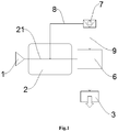
- the clothing treatment apparatus of the present disclosure includes a clothing treatment drum, a water supply valve 1, a dispensing device 2, a water-containing member, an atomization generator 3, and a one-way check mechanism.
- the dispensing device 2 includes a water delivery channel 21, the water supply valve 1 is connected to a water inlet end of the water delivery channel 21, and a water outlet end of the water delivery channel 21 is connected to the atomization generator 3 through the water-containing member.
- An outlet of the atomization generator 3 is arranged facing an inner cavity of the clothing treatment drum.
- the one-way check mechanism is connected with the water delivery channel 21 and the water-containing member respectively, and the one-way check mechanism is arranged to be isolated from the atmosphere when the water supply valve 1 is opened and to communicate with the atmosphere when the water supply valve 1 is closed.
- the water-containing member may be a water tank, or a water box, or a sink on the clothing treatment apparatus. Those skilled in the art may flexibly set the specific structure of the water-containing member in practical applications, as long as the water-containing member can store and accommodate water.
- the atomization generator 3 may be an ultrasonic atomization generator or a compressed atomization generator.
- the atomization generator 3 may flexibly set the specific structure of the atomization generator 3 in practical applications, as long as the atomization generator 3 can convert the water in the water delivery channel 21 and the water-containing member into atomized water droplets when the one-way check structure communicates with the atmosphere so as to perform atomized air washing of the clothing.
- a combined structure of a one-way check valve 7 and pipelines may be used as the one-way check structure, in which the one-way check valve 7 may be the one-way check valve in the patent No. 201721853840.8 .
- the principle of the one-way check valve 7 belongs to the prior art, so it will not be described in detail herein.
- the one-way check structure includes a cylinder, a movable block arranged in the cylinder, and a spring connected between the cylinder and the movable block.
- the movable block divides an internal cavity of the cylinder into two parts. A top part of the cylinder is provided with an air inlet, a bottom part of the cylinder is provided with a water inlet, and a middle part of the cylinder is provided with an outlet.
- the spring allows the movable block to move between a top limit position, a middle position and a bottom limit position. When the spring is in a natural state, it enables the movable block to be maintained at the bottom limit position.
- the air inlet communicates with the outlet, and the water inlet is isolated from the outlet by the movable block, so as to realize the communication between the one-way check structure and the atmosphere.
- the water pressure moves the movable block to the top limit position against the force of the spring, so that the water inlet communicates with the outlet, and that the air inlet is isolated from the outlet by the movable block. Therefore, the one-way check structure allows water to pass through and be isolated from the atmosphere.
- the above-mentioned top part and bottom part are defined relative to the cylinder, and they do not constitute restrictions to the specific direction of arranging the one-way check structure.
- the one-way check structure may also be a combined structure of a plug and pipelines.
- the water delivery channel 21 and the water-containing member are connected by a connection pipe, an opening is provided at the highest point of the connection pipe, and a plug is provided at the opening.
- the plug is removed and the opening communicates with the atmosphere, so that the water in the water delivery channel 21 and the water-containing member is sprayed from the outlet of the atomization generator 3.
- Those skilled in the art may flexibly set the specific structure of the one-way check structure in practical applications, as long as the one-way check structure can be isolated from the atmosphere when the water supply valve 1 is opened and can communicate with the atmosphere when the water supply valve 1 is closed.
- the present disclosure enables the atomization generator 3 to smoothly generate atomized water droplets. This is because when the water supply valve 1 is always open, it is very difficult for the atomization generator 3 to form atomized water droplets under the action of water pressure. Therefore, the water supply valve 1 can be opened to accumulate water in the water delivery channel 21 and the water-containing member, and then the water supply valve 1 can be closed. At this time, the water in the water delivery channel 21 and the water-containing member can be sprayed onto the clothing in the form of atomized water droplets from the atomization generator 3 according to the principle of atmospheric communication, so as to ensure that the atomization generator 3 can perform atomized air washing of the clothing.
- the clothing treatment apparatus of the present disclosure may be a drum washing machine, a pulsator washing machine, a washing-drying integrated machine, a clothing care machine, etc., and those skilled in the art may flexibly set the application objects of the technical solutions of the present disclosure. Such adjustments and changes to the application objects do not deviate from the principle of the present disclosure, and should be defined within the scope of protection of the present disclosure.
- the technical solutions of the present disclosure will be further explained below in conjunction with a drum washing machine.
- the drum washing machine of the present disclosure includes a cabinet, a drum 4 arranged in the cabinet, and a window gasket 5 connected between an outer cylinder of the drum 4 and the cabinet.
- the atomization generator 3 is preferably arranged on the window gasket 5, and an outlet of the atomization generator 3 is obliquely arranged facing an inner cavity of the drum 4 (of course, other directions of arrangement are also possible).
- the atomization generator 3 may also be provided on the outer cylinder of the drum 4, as long as it can spray atomized water droplets onto the clothing in an inner cylinder of the drum 4 to perform atomized air washing.
- the drum washing machine also includes a dispensing device 2 arranged on the cabinet.
- the dispensing device 2 includes a clothing treatment agent dispensing cavity and a water box arranged on a top of the clothing treatment agent dispensing cavity.
- the water delivery channel 21 is formed in the water box.
- a water inlet end of the water delivery channel 21 is connected to the water supply valve 1 arranged outside of the dispensing device 2, and a water outlet end of the water delivery channel 21 is connected to a water tank 6 through a pipeline.
- the water tank 6 is connected to the atomization generator 3 through a pipeline, and the water tank 6 has a function of accumulating water.
- the one-way check valve 7 is arranged outside of the water delivery channel 21 and the water tank 6, the one-way check valve 7 is connected to the water delivery channel 21 through a first pipeline 8, and the one-way check valve 7 is also connected to the water tank 6 through a second pipeline 9 (this part of the structure is not shown in FIG. 2 ).
- the position where the one-way check valve 7 is arranged is at a different height from the position where the outlet of the atomization generator 3 is arranged, that is, when the one-way check valve 7 communicates with the atmosphere, a certain liquid level difference can be formed between the one-way check valve 7 and the outlet of the atomization generator 3, so that the water accumulated in the water delivery channel 21 and the water tank 6 can be sprayed onto the clothing more easily in the form of atomized water droplets through the atomization generator 3.
- the position where the dispensing device 2 is arranged is generally higher than the position where the drum 4 is arranged in the drum washing machine, it is more preferable to set the position where the one-way check valve 7 is arranged to be higher than the position where the outlet of the atomization generator 3 is arranged, thereby making full use of the original structure of the drum washing machine.
- the clothing treatment apparatus of the present disclosure includes a clothing treatment drum, a water supply valve 1, a dispensing device 2, a water-containing member, and an atomization generator 3.
- the dispensing device 2 includes a water delivery channel 21, the water supply valve 1 is connected to a water inlet end of the water-containing member through the water delivery channel 21, a water outlet end of the water-containing member is connected to the atomization generator 3 through a first pipeline 9, and the water outlet end of the water-containing member is also connected to the clothing treatment drum through a second pipeline 10.
- An outlet of the atomization generator 3 is arranged facing an inner cavity of the clothing treatment drum.
- the water delivery channel 21 and/or the water-containing member are provided with a one-way check mechanism, and the one-way check mechanism is arranged to be isolated from the atmosphere when the water supply valve 1 is opened and to communicate with the atmosphere when the water supply valve 1 is closed.
- the water-containing member may be a water tank, or a water box, or a sink on the clothing treatment apparatus. Those skilled in the art may flexibly set the specific structure of the water-containing member in practical applications, as long as the water-containing member can store and accommodate water.
- the atomization generator 3 may be an ultrasonic atomization generator or a compressed atomization generator.
- a one-way check valve 8 may be used as the one-way check structure, such as the one-way check valve 8 in the patent No. 201721853840.8 .
- the principle of the one-way check valve 8 belongs to the prior art, so it will not be described in detail herein. Of course, in the present disclosure, other one-way check structures may also be used.
- the one-way check structure includes a cylinder, a movable block arranged in the cylinder, and a spring connected between the cylinder and the movable block.
- the movable block divides an internal cavity of the cylinder into two parts. A top part of the cylinder is provided with an air inlet, a bottom part of the cylinder is provided with a water inlet, and a middle part of the cylinder is provided with an outlet.
- the spring allows the movable block to move between a top limit position, a middle position and a bottom limit position. When the spring is in a natural state, it enables the movable block to be maintained at the bottom limit position.
- the air inlet communicates with the outlet, and the water inlet is isolated from the outlet by the movable block, so as to realize the communication between the one-way check structure and the atmosphere.
- the water pressure moves the movable block to the top limit position against the force of the spring, so that the water inlet communicates with the outlet, and that the air inlet is isolated from the outlet by the movable block. Therefore, the one-way check structure allows water to pass through and be isolated from the atmosphere.
- the above-mentioned top part and bottom part are defined relative to the cylinder, and they do not constitute restrictions to the specific direction and specific position of arranging the one-way check structure.
- the one-way check structure may also be a plug structure. Specifically, an opening is provided at the highest point of the water delivery channel 21 and/or the water-containing member, and a plug is provided at the opening. When water inflows from the water supply valve 1, the opening is closed by the plug, and when the water supply valve 1 is closed, the plug is removed and the opening communicates with the atmosphere, so that the water in the water-containing member is sprayed from the outlet of the atomization generator 3.
- Those skilled in the art may flexibly set the specific structure of the one-way check structure in practical applications, as long as the one-way check structure can be isolated from the atmosphere when the water supply valve 1 is opened and can communicate with the atmosphere when the water supply valve 1 is closed.
- the one-way check structure only on the water delivery channel 21.
- the water delivery channel 21 and the water-containing member may also be provided with a one-way check structure respectively, so that when the one-way check structure communicates with the atmosphere, the water in the water delivery channel 21 and the water in the water-containing member will both flow into the interior of the clothing treatment drum through the atomization generator 3.
- the one-way check structure communicates with the atmosphere, at least the water in the water-containing member can flow into the interior of the clothing treatment drum through the atomization generator 3.
- the first pipeline 9 and the second pipeline 10 may be connected to the water delivery channel 21 through the same water outlet end of the water delivery channel 21, or they may also be connected to the water delivery channel 21 through different water outlet ends of the water delivery channel 21 respectively.
- the present disclosure enables the atomization generator 3 to smoothly generate atomized water droplets. This is because when the water supply valve 1 is always open, it is very difficult for the atomization generator 3 to form atomized water droplets under the action of water pressure. Therefore, the water supply valve 1 can be opened to accumulate water in the water delivery channel 21 and the water-containing member, and then the water supply valve 1 can be closed (the second pipeline 10 is selectively closed at this time).
- the atomization generator 3 is closed at this time so as to keep the water supply valve 1 always open and ensure that the second pipeline 10 is in a communicated state, thereby achieving continuous water injection into the clothing treatment drum.
- the second pipeline 10 can be directly connected to a water injection port or sprinkling structure on the clothing treatment drum.
- the clothing treatment apparatus of the present disclosure may be a drum washing machine, a pulsator washing machine, a washing-drying integrated machine, a clothing care machine, etc., and those skilled in the art may flexibly set the application objects of the technical solutions of the present disclosure. Such adjustments and changes to the application objects do not deviate from the principle of the present disclosure, and should be defined within the scope of protection of the present disclosure.
- the technical solutions of the present disclosure will be further explained below in conjunction with a drum washing machine.
- the drum washing machine of the present disclosure includes a cabinet, a drum 4 arranged in the cabinet, and a window gasket 5 connected between an outer cylinder of the drum 4 and the cabinet.
- the atomization generator 3 is preferably arranged on the window gasket 5, and an outlet of the atomization generator 3 is obliquely arranged facing an inner cavity of the drum 4 (of course, other directions of arrangement are also possible).
- the atomization generator 3 may also be provided on the outer cylinder of the drum 4, as long as it can spray atomized water droplets onto the clothing in an inner cylinder of the drum 4 to perform atomized air washing.
- a sprinkling head 7 is provided on the drum 4 or on the window gasket 5, and an outlet of the sprinkling head 7 is also arranged facing the inner cavity of the drum 4.
- the sprinkling head 7 is mainly configured to sprinkle water into the drum 4.
- a control valve may be selectively installed on the second pipeline 10, and the control valve can control on and off of the second pipeline 10.
- the drum washing machine also includes a dispensing device 2 arranged on the cabinet.
- the dispensing device 2 includes a clothing treatment agent dispensing cavity and a water box arranged on a top of the clothing treatment agent dispensing cavity.
- the water delivery channel 21 is formed in the water box.
- a water inlet end of the water delivery channel 21 is connected to the water supply valve 1 arranged outside of the dispensing device 2, and a water outlet end of the water delivery channel 21 is connected to a water tank 6 through a pipeline.
- the water tank 6 is connected to the atomization generator 3 through the first pipeline 9, and is connected to the sprinkling head 7 through the second pipeline 10.
- the water tank 6 has a function of accumulating water.
- the one-way check valve 8 is arranged on the water delivery channel 21.
- the one-way check valve 8 may be arranged close to the water inlet end of the water delivery channel 21.
- the one-way check valve 8 may also be arranged at other positions of the water delivery channel 21.
- the position where the one-way check valve 8 is arranged is at a different height from the position where the outlet of the atomization generator 3 is arranged, that is, when the one-way check valve 8 communicates with the atmosphere, a certain liquid level difference can be formed between the one-way check valve 8 and the outlet of the atomization generator 3, so that the water accumulated in the water delivery channel 21 and the water tank 6 can be sprayed onto the clothing more easily in the form of atomized water droplets through the atomization generator 3.
- the position where the dispensing device 2 is arranged is generally higher than the position where the drum 4 is arranged in the drum washing machine, it is more preferable to set the position where the one-way check valve 8 is arranged to be higher than the position where the outlet of the atomization generator 3 is arranged, thereby making full use of the original structure of the drum washing machine.
- the clothing treatment apparatus of the present disclosure includes a clothing treatment drum, a water supply valve 1, a dispensing device 2, a water-containing member, and an atomization generator 3.
- the dispensing device 2 includes a water delivery channel 21, the water supply valve 1 is connected to a water inlet end of the water delivery channel 21, and a water outlet end of the water delivery channel 21 is connected to the atomization generator 3 through the water-containing member.
- An outlet of the atomization generator 3 is arranged facing an inner cavity of the clothing treatment drum.
- the water delivery channel 21 and/or the water-containing member are provided with a one-way check mechanism, and the one-way check mechanism is arranged to be isolated from the atmosphere when the water supply valve 1 is opened and to communicate with the atmosphere when the water supply valve 1 is closed.
- the water-containing member may be a water tank, or a water box, or a sink on the clothing treatment apparatus. Those skilled in the art may flexibly set the specific structure of the water-containing member in practical applications, as long as the water-containing member can store and accommodate water.
- the atomization generator 3 may be an ultrasonic atomization generator or a compressed atomization generator.
- a one-way check valve 7 may be used as the one-way check structure, such as the one-way check valve 7 in the patent No. 201721853840.8 .
- the principle of the one-way check valve 7 belongs to the prior art, so it will not be described in detail herein. Of course, in the present disclosure, other one-way check structures may also be used.
- the one-way check structure includes a cylinder, a movable block arranged in the cylinder, and a spring connected between the cylinder and the movable block.
- the movable block divides an internal cavity of the cylinder into two parts. A top part of the cylinder is provided with an air inlet, a bottom part of the cylinder is provided with a water inlet, and a middle part of the cylinder is provided with an outlet.
- the spring allows the movable block to move between a top limit position, a middle position and a bottom limit position. When the spring is in a natural state, it enables the movable block to be maintained at the bottom limit position.
- the air inlet communicates with the outlet, and the water inlet is isolated from the outlet by the movable block, so as to realize the communication between the one-way check structure and the atmosphere.
- the water pressure moves the movable block to the top limit position against the force of the spring, so that the water inlet communicates with the outlet, and that the air inlet is isolated from the outlet by the movable block. Therefore, the one-way check structure allows water to pass through and be isolated from the atmosphere.
- the above-mentioned top part and bottom part are defined relative to the cylinder, and they do not constitute restrictions to the specific direction and specific position of arranging the one-way check structure.
- the one-way check structure may also be a plug structure. Specifically, an opening is provided at the highest point of the water delivery channel 21 and/or the water-containing member, and a plug is provided at the opening. When water inflows from the water supply valve 1, the opening is closed by the plug, and when the water supply valve 1 is closed, the plug is removed and the opening communicates with the atmosphere, so that the water in the water-containing member is sprayed from the outlet of the atomization generator 3.
- Those skilled in the art may flexibly set the specific structure of the one-way check structure in practical applications, as long as the one-way check structure can be isolated from the atmosphere when the water supply valve 1 is opened and can communicate with the atmosphere when the water supply valve 1 is closed.
- the one-way check structure only on the water delivery channel 21.
- the water delivery channel 21 and the water-containing member may also be provided with a one-way check structure respectively, so that when the one-way check structure communicates with the atmosphere, the water in the water delivery channel 21 and the water in the water-containing member will both flow into the interior of the clothing treatment drum through the atomization generator 3.
- the one-way check structure communicates with the atmosphere, at least the water in the water-containing member can flow into the interior of the clothing treatment drum through the atomization generator 3.
- Those skilled in the art may flexibly set the arrangement position and distribution of the one-way check structure in practical applications, as long as it can be ensured that at least the water in the water-containing member can flow into the interior of the clothing treatment drum through the atomization generator 3 to realize the atomized air washing of the clothing.
- the present disclosure enables the atomization generator 3 to smoothly generate atomized water droplets. This is because when the water supply valve 1 is always open, it is very difficult for the atomization generator 3 to form atomized water droplets under the action of water pressure. Therefore, the water supply valve 1 can be opened to accumulate water in the water delivery channel 21 and the water-containing member, and then the water supply valve 1 can be closed. At this time, at least the water in the water-containing member can be sprayed onto the clothing in the form of atomized water droplets from the atomization generator 3 according to the principle of atmospheric communication, so as to ensure that the atomization generator 3 can perform atomized air washing of the clothing.
- the clothing treatment apparatus of the present disclosure may be a drum washing machine, a pulsator washing machine, a washing-drying integrated machine, a clothing care machine, etc., and those skilled in the art may flexibly set the application objects of the technical solutions of the present disclosure. Such adjustments and changes to the application objects do not deviate from the principle of the present disclosure, and should be defined within the scope of protection of the present disclosure.
- the technical solutions of the present disclosure will be further explained below in conjunction with a drum washing machine.
- the drum washing machine of the present disclosure includes a cabinet, a drum 4 arranged in the cabinet, and a window gasket 5 connected between an outer cylinder of the drum 4 and the cabinet.
- the atomization generator 3 is preferably arranged on the window gasket 5, and an outlet of the atomization generator 3 is obliquely arranged facing an inner cavity of the drum 4 (of course, other directions of arrangement are also possible).
- the atomization generator 3 may also be provided on the outer cylinder of the drum 4, as long as it can spray atomized water droplets onto the clothing in an inner cylinder of the drum 4 to perform atomized air washing.
- the drum washing machine also includes a dispensing device 2 arranged on the cabinet.
- the dispensing device 2 includes a clothing treatment agent dispensing cavity and a water box arranged on a top of the clothing treatment agent dispensing cavity.
- the water delivery channel 21 is formed in the water box.
- a water inlet end of the water delivery channel 21 is connected to the water supply valve 1 arranged outside of the dispensing device 2, and a water outlet end of the water delivery channel 21 is connected to a water tank 6 through a pipeline.
- the water tank 6 is connected to the atomization generator 3 through a pipeline, and the water tank 6 has a function of accumulating water.
- the one-way check valve 7 is arranged on the water delivery channel 21.
- the one-way check valve 7 may be arranged close to the water inlet end of the water delivery channel 21.
- the one-way check valve 7 may also be arranged at other positions of the water delivery channel 21. Those skilled in the art may flexibly set the position where the one-way check valve 7 is arranged in the water delivery channel 21 in practical applications. Such adjustments and changes to the arrangement position of the one-way check valve 7 do not constitute limitations to the present disclosure, and should be defined within the scope of protection of the present disclosure.
- the position where the one-way check valve 7 is arranged is at a different height from the position where the outlet of the atomization generator 3 is arranged, that is, when the one-way check valve 7 communicates with the atmosphere, a certain liquid level difference can be formed between the one-way check valve 7 and the outlet of the atomization generator 3, so that the water accumulated in the water delivery channel 21 and the water tank 6 can be sprayed onto the clothing more easily in the form of atomized water droplets through the atomization generator 3.
- the position where the dispensing device 2 is arranged is generally higher than the position where the drum 4 is arranged in the drum washing machine, it is more preferable to set the position where the one-way check valve 7 is arranged to be higher than the position where the outlet of the atomization generator 3 is arranged, thereby making full use of the original structure of the drum washing machine.
- the clothing treatment apparatus of the present disclosure includes a clothing treatment drum, a water supply valve 1, a dispensing device 2, and an atomization generator 3.
- the dispensing device 2 includes a water delivery channel 21, the water supply valve 1 is connected to a water inlet end of the water delivery channel 21, a water outlet end of the water delivery channel 21 is connected to the atomization generator 3 through a first pipeline 4, and the water outlet end of the water delivery channel 21 is also connected to a second pipeline 5.
- An outlet of the second pipeline 5 is arranged facing an inner cavity of the clothing treatment drum, an outlet of the atomization generator 3 is arranged facing an inner cavity of the clothing treatment drum, and the second pipeline 5 is arranged to be able to communicate with the atmosphere.
- the second pipeline 5 may be directly connected to the clothing treatment drum, and the outlet of the second pipeline 5 may also be arranged above the clothing treatment drum.
- Those skilled in the art may flexibly set the ways of arranging and connecting the second pipeline 5 in practical applications, as long as water can be injected into the clothing treatment drum through the second pipeline 5.
- the technical solution of the present disclosure may also be applied to a clothing treatment apparatus with a multi-drum structure, such as a dual-drum washing machine, which includes a first drum and a second drum.
- the outlet of the atomization generator 3 is arranged facing an inner cavity of the first drum, and the outlet of the second pipeline 5 is arranged facing an inner cavity of the second drum, so that water can be injected into the first drum and the second drum through the same water supply valve 1.
- Atomized water injection is implemented in the first drum (in which other water injection structures may also be included), and direct water injection is implemented in the second drum (including water injection by sprinkling, etc.).
- the atomization generator 3 may be an ultrasonic atomization generator or a compressed atomization generator.
- Those skilled in the art may flexibly set the specific structure of the atomization generator 3 in practical applications, as long as the atomization generator 3 can convert the water in the water delivery channel 21 and the first pipeline 4 into atomized water droplets when the second pipeline 5 communicates with the atmosphere so as to perform atomized air washing of the clothing.
- the second pipeline 5 of the present disclosure may be a structure that is always in communication with the atmosphere.
- the outlet of the second pipeline 5 is arranged above the clothing treatment drum, and the outlet of the second pipeline 5 is arranged facing the inner cavity of the clothing treatment drum.
- the second pipeline 5 may also be a structure that can selectively communicate with the atmosphere. The technical solution of the present disclosure will be further explained below in conjunction with this structure.
- the second pipeline 5 includes a pipeline body and a one-way check structure provided on the pipeline body, and the one-way check structure is arranged to be isolated from the atmosphere when the water supply valve 1 is opened and to communicate with the atmosphere when the water supply valve 1 is closed.
- a one-way check valve may be used as the one-way check structure, such as the one-way check valve in the patent No. 201721853840.8 .
- the principle of the one-way check valve belongs to the prior art, so it will not be described in detail herein. Of course, in the present disclosure, other one-way check structures may also be used.
- the one-way check structure includes a cylinder, a movable block arranged in the cylinder, and a spring connected between the cylinder and the movable block.
- the movable block divides an internal cavity of the cylinder into two parts. A top part of the cylinder is provided with an air inlet, a bottom part of the cylinder is provided with a water inlet, and a middle part of the cylinder is provided with an outlet.
- the spring allows the movable block to move between a top limit position, a middle position and a bottom limit position. When the spring is in a natural state, it enables the movable block to be maintained at the bottom limit position.
- the air inlet communicates with the outlet, and the water inlet is isolated from the outlet by the movable block, so as to realize the communication between the one-way check structure and the atmosphere.
- the water pressure moves the movable block to the top limit position against the force of the spring, so that the water inlet communicates with the outlet, and that the air inlet is isolated from the outlet by the movable block. Therefore, the one-way check structure allows water to pass through and be isolated from the atmosphere.
- the above-mentioned top part and bottom part are defined relative to the cylinder, and they do not constitute restrictions to the specific direction and specific position of arranging the one-way check structure.
- the one-way check structure may also be a plug structure. Specifically, an opening is provided at the highest point of the second pipeline 5, and a plug is provided at the opening. When water inflows from the water supply valve 1, the opening is closed by the plug, and when the water supply valve 1 is closed, the plug is removed and the opening communicates with the atmosphere, so that the water in the water delivery channel 21 and the first pipeline 4 is sprayed from the outlet of the atomization generator 3.
- Those skilled in the art may flexibly set the specific structure of the one-way check structure in practical applications, as long as the one-way check structure can be isolated from the atmosphere when the water supply valve 1 is opened and can communicate with the atmosphere when the water supply valve 1 is closed.
- the water supply valve 1 when the water supply valve 1 is closed, a part of the water in the water delivery channel 21 enters the first pipeline 4 and the other part of the water enters the second pipeline 5.
- the first pipeline 4 and the second pipeline 5 may be connected to the water delivery channel 21 through the same water outlet end of the water delivery channel 21, or may also be connected to the water delivery channel 21 through different water outlet ends of the water delivery channel 21 respectively.
- the present disclosure enables the atomization generator to smoothly generate atomized water droplets. This is because when the water supply valve is always open, it is very difficult for the atomization generator to form atomized water droplets under the action of water pressure. Therefore, the water supply valve can be opened to accumulate water in the water delivery channel, and then the water supply valve can be closed. At this time, the water in the water delivery channel and the first pipeline can be sprayed onto the clothing in the form of atomized water droplets from the atomization generator according to the principle of atmospheric communication, so as to ensure that the atomization generator can perform atomized air washing of the clothing.
- the clothing treatment apparatus of the present disclosure may be a drum washing machine, a pulsator washing machine, a washing-drying integrated machine, a clothing care machine, etc., and those skilled in the art may flexibly set the application objects of the technical solutions of the present disclosure. Such adjustments and changes to the application objects do not deviate from the principle of the present disclosure, and should be defined within the scope of protection of the present disclosure.
- the technical solutions of the present disclosure will be further explained below in conjunction with a drum washing machine.
- the drum washing machine of the present disclosure includes a cabinet, a drum arranged in the cabinet, and a window gasket connected between an outer cylinder of the drum and the cabinet.
- the atomization generator is preferably arranged on the window gasket, and an outlet of the atomization generator is obliquely arranged facing an inner cavity of the drum (of course, other directions of arrangement are also possible).
- the atomization generator may also be provided on the outer cylinder of the drum, as long as it can spray atomized water droplets onto the clothing in an inner cylinder of the drum to perform atomized air washing.
- the drum washing machine also includes a dispensing device arranged on the cabinet.
- the dispensing device includes a clothing treatment agent dispensing cavity and a water box arranged on a top of the clothing treatment agent dispensing cavity.
- the water delivery channel is formed in the water box (that is, the clothing treatment agent dispensing cavity is arranged below the water delivery channel).
- a water inlet end of the water delivery channel is connected to the water supply valve arranged outside of the dispensing device, a water outlet end of the water delivery channel is connected to the atomization generator through the first pipeline, and the water outlet end of the water delivery channel is also directly connected to the outer cylinder of the drum through the second pipeline.
- the one-way check valve is provided on the second pipeline.
- the water outlet end of the water delivery channel may be directly connected to the atomization generator through the first pipeline, and a water tank may also be arranged between the water delivery channel and the atomization generator; that is, the water outlet end of the water delivery channel is first connected to the water tank through a pipeline, and then the water tank is connected to the atomization generator through another pipeline.
- the water tank has a function of accumulating water.
- the position where the one-way check valve is arranged is at a different height from the position where the outlet of the atomization generator is arranged, that is, when the one-way check valve communicates with the atmosphere, a certain liquid level difference can be formed between the one-way check valve and the outlet of the atomization generator, so that the water accumulated in the water delivery channel and the first pipeline can be sprayed onto the clothing more easily in the form of atomized water droplets through the atomization generator.
- the position where the dispensing device is arranged is generally higher than the position where the drum is arranged in the drum washing machine, it is more preferable to set the position where the one-way check valve is arranged to be higher than the position where the outlet of the atomization generator is arranged, thereby making full use of the original structure of the drum washing machine.
Landscapes
- Engineering & Computer Science (AREA)
- Textile Engineering (AREA)
- Detail Structures Of Washing Machines And Dryers (AREA)
- Accessory Of Washing/Drying Machine, Commercial Washing/Drying Machine, Other Washing/Drying Machine (AREA)
Abstract
Description
- The present disclosure belongs to the technical field of clothing treatment, and specifically provides a clothing treatment apparatus.
- A clothing treatment apparatus is an apparatus capable of washing, drying, sterilizing and/or deodorizing clothing. With the continuous improvement of production level and ongoing growth of users' needs, users have also raised higher and higher requirements on the clothing treatment apparatus.
- In the prior art, taking a washing machine as an example, the clothing is generally washed by water. The washing process is accompanied by mechanical rotation, so that stains on the clothing are washed away. However, this washing method has a limitation in that if a large amount of water is injected into a washing drum at the beginning, the stains on a surface of the clothing will directly enter a lining of the clothing in a state where a washing liquid is not completely dissolved, so that more time, water amount, washing liquid and mechanical action are required for washing the clothing clean in the subsequent washing process, thus resulting in a poor washing effect. In existing clothing treatment apparatuses, other functions are often added on the basis of a washing machine, such as adding a drying function to become a washing-drying integrated machine, etc. Such an improvement does not significantly improve the washing effect of the washing machine. Moreover, current washing machines still cannot achieve in-depth treatment of clothing made of special materials, such as cashmere, wool and other materials. If the traditional washing by water is used, it is highly possible that fiber structures of the clothing will be damaged, which has caused a very big limitation on an applicable range of the clothing of the washing machine.
- Accordingly, there is a need for a new clothing treatment apparatus in the art to solve the above problems.
- In order to solve the above problems in the prior art, that is, to solve the problems of poor washing effect and very limited applicable range of clothing of existing clothing treatment apparatuses with a washing function, the present disclosure provides a clothing treatment apparatus.
- A first technical solution of the present disclosure provides a clothing treatment apparatus, and the clothing treatment apparatus includes a clothing treatment drum, a water supply valve, a dispensing device, a water-containing member, an atomization generator and a one-way check mechanism; in which the dispensing device includes a water delivery channel, the water supply valve is connected to a water inlet end of the water delivery channel, and a water outlet end of the water delivery channel is connected to the atomization generator through the water-containing member; an outlet of the atomization generator is arranged facing an inner cavity of the clothing treatment drum, the one-way check mechanism is connected to the water delivery channel and the water-containing member respectively, and the one-way check mechanism is arranged to be isolated from the atmosphere when the water supply valve is opened and to communicate with the atmosphere when the water supply valve is closed.
- In a preferred technical solution of the above clothing treatment apparatus, the dispensing device further includes a clothing treatment agent dispensing cavity, and the clothing treatment agent dispensing cavity is arranged below the water delivery channel.
- In a preferred technical solution of the above clothing treatment apparatus, the water supply valve is arranged outside of the dispensing device.
- In a preferred technical solution of the above clothing treatment apparatus, a position where the one-way check structure is arranged is at a different height from a position where the outlet of the atomization generator is arranged.
- In a preferred technical solution of the above clothing treatment apparatus, the position where the one-way check structure is arranged is higher than the position where the outlet of the atomization generator is arranged.
- In a preferred technical solution of the above clothing treatment apparatus, the outlet of the atomization generator is arranged obliquely.
- In a preferred technical solution of the above clothing treatment apparatus, the one-way check mechanism includes a one-way check valve, a first pipeline and a second pipeline, the one-way check valve is connected to the water delivery channel through the first pipeline, and the one-way check valve is connected to the water-containing member through the second pipeline.
- In a preferred technical solution of the above clothing treatment apparatus, the clothing treatment apparatus is a drum washing machine, and the clothing treatment drum is a drum of the drum washing machine.
- In a preferred technical solution of the above clothing treatment apparatus, the drum washing machine further includes a window gasket connected to the drum, and the atomization generator is arranged on the window gasket.
- In a preferred technical solution of the above clothing treatment apparatus, the atomization generator is arranged on an outer cylinder of the drum.
- It can be understood by those skilled in the art that in the preferred technical solutions of the present disclosure, by connecting the one-way check structure with the water delivery channel and the water-containing member, water can be injected into the water delivery channel and the water-containing member when the water supply valve is opened, and then the one-way check structure communicates with the atmosphere when the water supply valve is closed, so that the water in the water delivery channel and the water-containing member is sprayed from the atomization generator, and the water is converted into small particles of atomized water droplets under the atomization action of the atomization generator, thereby realizing a tender treatment of the clothing by atomized air. Specifically, before washing by water, the clothing can be moistened first by atomized water droplets, so that the stains on the surface of the clothing are removed first, preventing the stains on the surface of the clothing from entering the lining of the clothing. Therefore, less time, water amount, washing liquid and mechanical action can be used to wash the clothing clean in the subsequent washing process so that the washing effect on the clothing is improved and the clothing treatment apparatus is more energy-saving. In addition, the use of this atomized air washing method can treat clothing of special materials such as cashmere, wool, etc., which not only can make the surface of the clothing of this material smoother and softer, but also can quickly remove stains on the clothing without damaging the fiber structures of the clothing, thereby increasing the applicable range of the clothing of the clothing treatment apparatus and further improving the user experience.
- Further, by setting the position where the one-way check structure is arranged at a different height from the position where the outlet of the atomization generator is arranged, a certain liquid level difference is formed, so that the water in the water delivery channel and the water-containing member can be smoothly sprayed from the outlet of the atomization generator, which makes it easier to perform the atomized air washing of the clothing and improves the user experience.
- A second technical solution of the present disclosure provides a clothing treatment apparatus, and the clothing treatment apparatus includes a clothing treatment drum, a water supply valve, a dispensing device, a water-containing member, and an atomization generator; in which the dispensing device includes a water delivery channel, the water supply valve is connected to a water inlet end of the water-containing member through the water delivery channel, a water outlet end of the water-containing member is connected to the atomization generator through a first pipeline, and the water outlet end of the water-containing member is also connected to the clothing treatment drum through a second pipeline; an outlet of the atomization generator is arranged facing an inner cavity of the clothing treatment drum, the water delivery channel and/or the water-containing member is provided with a one-way check structure, and the one-way check mechanism is arranged to be isolated from the atmosphere when the water supply valve is opened and to communicate with the atmosphere when the water supply valve is closed.
- In a preferred technical solution of the above clothing treatment apparatus, a sprinkling head is provided on the clothing treatment drum, and the second pipeline is connected with the sprinkling head.
- In a preferred technical solution of the above clothing treatment apparatus, a sprinkling port of the sprinkling head is arranged facing the inner cavity of the clothing treatment drum.
- In a preferred technical solution of the above clothing treatment apparatus, the one-way check structure is arranged close to the water inlet end of the water delivery channel.
- In a preferred technical solution of the above clothing treatment apparatus, a position where the one-way check structure is arranged is at a different height from a position where the outlet of the atomization generator is arranged.
- In a preferred technical solution of the above clothing treatment apparatus, the position where the one-way check structure is arranged is higher than the position where the outlet of the atomization generator is arranged.
- In a preferred technical solution of the above clothing treatment apparatus, the one-way check structure is a one-way check valve.
- In a preferred technical solution of the above clothing treatment apparatus, the clothing treatment apparatus is a drum washing machine, and the clothing treatment drum is a drum of the drum washing machine.
- In a preferred technical solution of the above clothing treatment apparatus, the drum washing machine further includes a window gasket connected to the drum, and the atomization generator is arranged on the window gasket.
- In a preferred technical solution of the above clothing treatment apparatus, the atomization generator is arranged on an outer cylinder of the drum.
- It can be understood by those skilled in the art that in the preferred technical solutions of the present disclosure, by arranging the one-way check structure on the water delivery channel and/or the water-containing member, water can be injected into the water delivery channel and the water-containing member when the water supply valve is opened, and then the one-way check structure communicates with the atmosphere when the water supply valve is closed, so that the water in the water-containing member is sprayed from the atomization generator, and the water is converted into small particles of atomized water droplets under the atomization action of the atomization generator, thereby realizing a tender treatment of the clothing by atomized air. In addition, other ways of water injection, such as sprinkling, may be provided by connecting the second pipeline to the clothing treatment drum. Specifically, before washing by water, the clothing can be moistened first by atomized water droplets, so that the stains on the surface of the clothing are removed first, preventing the stains on the surface of the clothing from entering the lining of the clothing. After the atomized air washing, water is injected into the clothing treatment drum through the second pipeline. Therefore, less time, water amount, washing liquid and mechanical action can be used to wash the clothing clean in the subsequent washing process so that the washing effect on the clothing is improved and the clothing treatment apparatus is more energy-saving. In addition, the use of this atomized air washing method can treat clothing of special materials such as cashmere, wool, etc., which not only can make the surface of the clothing of this material smoother and softer, but also can quickly remove stains on the clothing without damaging the fiber structures of the clothing, thereby increasing the applicable range of the clothing of the clothing treatment apparatus and further improving the user experience.
- Further, the second pipeline is connected to the sprinkling head provided on the clothing treatment drum, so that the clothing treatment apparatus of the present disclosure has at least two clothing washing modes: atomized air washing and sprinkling washing, thus enabling the users to choose the corresponding washing mode flexibly according to their own needs to meet the various requirements of users and improve the user experience.
- Further, by setting the position where the one-way check structure is arranged at a different height from the position where the outlet of the atomization generator is arranged, a certain liquid level difference is formed, so that the water in the water-containing member can be smoothly sprayed from the outlet of the atomization generator, which makes it easier to perform the atomized air washing of the clothing and improves the user experience.
- A third technical solution of the present disclosure provides a clothing treatment apparatus, and the clothing treatment apparatus includes a clothing treatment drum, a water supply valve, a dispensing device, a water-containing member, and an atomization generator; in which the dispensing device includes a water delivery channel, the water supply valve is connected to a water inlet end of the water delivery channel, a water outlet end of the water delivery channel is connected to the atomization generator through the water-containing member; an outlet of the atomization generator is arranged facing an inner cavity of the clothing treatment drum, the water delivery channel and/or the water-containing member is provided with a one-way check structure, and the one-way check mechanism is arranged to be isolated from the atmosphere when the water supply valve is opened and to communicate with the atmosphere when the water supply valve is closed.
- In a preferred technical solution of the above clothing treatment apparatus, the one-way check structure is arranged close to the water inlet end of the water delivery channel.
- In a preferred technical solution of the above clothing treatment apparatus, the water supply valve is arranged outside of the dispensing device.
- In a preferred technical solution of the above clothing treatment apparatus, a position where the one-way check structure is arranged is at a different height from a position where the outlet of the atomization generator is arranged.
- In a preferred technical solution of the above clothing treatment apparatus, the position where the one-way check structure is arranged is higher than the position where the outlet of the atomization generator is arranged.
- In a preferred technical solution of the above clothing treatment apparatus, the outlet of the atomization generator is arranged obliquely.
- In a preferred technical solution of the above clothing treatment apparatus, the one-way check structure is a one-way check valve.
- In a preferred technical solution of the above clothing treatment apparatus, the clothing treatment apparatus is a drum washing machine, and the clothing treatment drum is a drum of the drum washing machine.
- In a preferred technical solution of the above clothing treatment apparatus, the drum washing machine further includes a window gasket connected to the drum, and the atomization generator is arranged on the window gasket.
- In a preferred technical solution of the above clothing treatment apparatus, the atomization generator is arranged on an outer cylinder of the drum.
- It can be understood by those skilled in the art that in the preferred technical solutions of the present disclosure, by arranging the one-way check structure on the water delivery channel and/or the water-containing member, water can be injected into the water delivery channel and the water-containing member when the water supply valve is opened, and then the one-way check structure communicates with the atmosphere when the water supply valve is closed, so that the water in the water-containing member is sprayed from the atomization generator, and the water is converted into small particles of atomized water droplets under the atomization action of the atomization generator, thereby realizing a tender treatment of the clothing by atomized air. Specifically, before washing by water, the clothing can be moistened first by atomized water droplets, so that the stains on the surface of the clothing are removed first, preventing the stains on the surface of the clothing from entering the lining of the clothing. Therefore, less time, water amount, washing liquid and mechanical action can be used to wash the clothing clean in the subsequent washing process so that the washing effect on the clothing is improved and the clothing treatment apparatus is more energy-saving. In addition, the use of this atomized air washing method can treat clothing of special materials such as cashmere, wool, etc., which not only can make the surface of the clothing of this material smoother and softer, but also can quickly remove stains on the clothing without damaging the fiber structures of the clothing, thereby increasing the applicable range of the clothing of the clothing treatment apparatus and further improving the user experience.
- Further, by setting the position where the one-way check structure is arranged at a different height from the position where the outlet of the atomization generator is arranged, a certain liquid level difference is formed, so that the water in the water-containing member can be smoothly sprayed from the outlet of the atomization generator, which makes it easier to perform the atomized air washing of the clothing and improves the user experience.
- A fourth technical solution of the present disclosure provides a clothing treatment apparatus, and the clothing treatment apparatus includes a clothing treatment drum, a water supply valve, a dispensing device and an atomization generator; in which the dispensing device includes a water delivery channel, the water supply valve is connected to a water inlet end of the water delivery channel, a water outlet end of the water delivery channel is connected to the atomization generator through a first pipeline, and the water outlet end of the water delivery channel is also connected to a second pipeline; an outlet of the second pipeline is arranged facing an inner cavity of the clothing treatment drum, an outlet of the atomization generator is arranged facing the inner cavity of the clothing treatment drum, and the second pipeline is arranged to be able to communicate with the atmosphere.
- In a preferred technical solution of the above clothing treatment apparatus, the second pipeline includes a pipeline body and a one-way check structure provided on the pipeline body, and the one-way check structure is arranged to be isolated from the atmosphere when the water supply valve is opened and to communicate with the atmosphere when the water supply valve is closed.
- In a preferred technical solution of the above clothing treatment apparatus, a position where the one-way check structure is arranged is at a different height from a position where the outlet of the atomization generator is arranged.
- In a preferred technical solution of the above clothing treatment apparatus, the position where the one-way check structure is arranged is higher than the position where the outlet of the atomization generator is arranged.
- In a preferred technical solution of the above clothing treatment apparatus, the one-way check structure is a one-way check valve.
- In a preferred technical solution of the above clothing treatment apparatus, the outlet of the atomization generator is arranged obliquely.
- In a preferred technical solution of the above clothing treatment apparatus, the dispensing device further includes a clothing treatment agent dispensing cavity, and the clothing treatment agent dispensing cavity is arranged below the water delivery channel.
- In a preferred technical solution of the above clothing treatment apparatus, the clothing treatment apparatus is a drum washing machine, and the clothing treatment drum is a drum of the drum washing machine.
- In a preferred technical solution of the above clothing treatment apparatus, the drum washing machine further includes a window gasket connected to the drum, and the atomization generator is arranged on the window gasket.
- In a preferred technical solution of the above clothing treatment apparatus, the atomization generator is arranged on an outer cylinder of the drum.
- It can be understood by those skilled in the art that in the preferred technical solutions of the present disclosure, water can be injected into the water delivery channel when the water supply valve is opened, and then when the water supply valve is closed, the second pipeline can communicate with the atmosphere, so that a part of the water in the water delivery channel and all the water in the first pipeline can be sprayed from the atomization generator, and can be converted into small particles of atomized water droplets under the atomization action of the atomization generator, thereby realizing a tender treatment of the clothing by atomized air. Specifically, before washing by water, the clothing can be moistened first by atomized water droplets, so that the stains on the surface of the clothing are removed first, preventing the stains on the surface of the clothing from entering the lining of the clothing. Therefore, less time, water amount, washing liquid and mechanical action can be used to wash the clothing clean in the subsequent washing process so that the washing effect on the clothing is improved and the clothing treatment apparatus is more energy-saving. In addition, the use of this atomized air washing method can treat clothing of special materials such as cashmere, wool, etc., which not only can make the surface of the clothing of this material smoother and softer, but also can quickly remove stains on the clothing without damaging the fiber structures of the clothing, thereby increasing the applicable range of the clothing of the clothing treatment apparatus and further improving the user experience.
- Further, by providing the one-way check structure, the one-way check structure is isolated from the atmosphere when the water supply valve is opened, so as to perform a normal water injection operation, and the one-way check structure communicates with the atmosphere when the water supply valve is closed, so that a part of the water in the water delivery channel and all the water in the first pipeline can be sprayed from the atomization generator to realize the atomized air washing of the clothing.
- Further, by setting the position where the one-way check structure is arranged at a different height from the position where the outlet of the atomization generator is arranged, a certain liquid level difference is formed, so that the water in the water delivery channel and the first pipeline can be smoothly sprayed from the outlet of the atomization generator, which makes it easier to perform the atomized air washing of the clothing and improves the user experience.
-
-
FIG. 1 is a partial structural view showing the principle of a clothing treatment apparatus according to a first technical solution of the present disclosure; -
FIG. 2 is a partial schematic view showing the structure of a drum washing machine according to the first technical solution of the present disclosure; -
FIG. 3 is a partial structural view showing the principle of a clothing treatment apparatus according to a second technical solution of the present disclosure; -
FIG. 4 is a partial schematic view showing the structure of a drum washing machine according to the second technical solution of the present disclosure; -
FIG. 5 is a partial structural view showing the principle of a clothing treatment apparatus according to a third technical solution of the present disclosure; -
FIG. 6 is a partial schematic view showing the structure of a drum washing machine according to the third technical solution of the present disclosure; and -
FIG. 7 is a partial structural view showing the principle of a clothing treatment apparatus according to a fourth technical solution of the present disclosure. - Preferred embodiments of the present disclosure will be described below with reference to the accompanying drawings. It should be understood by those skilled in the art that these embodiments are only used to explain the technical principles of the present disclosure, and are not intended to limit the scope of protection of the present disclosure.
- It should be noted that in the description of the present disclosure, terms indicating directional or positional relationships, such as "in", "above", "below", "inside", "outside" and the like, are based on the directional or positional relationships shown in the accompanying drawings. They are only used for ease of description, and do not indicate or imply that the device or element must have a specific orientation, or be constructed or operated in a specific orientation, and therefore they should not be considered as limitations to the present disclosure. In addition, terms "first" and "second" are only used for descriptive purposes, and should not be understood as indicating or implying relative importance.
- In addition, it should also be noted that in the description of the present disclosure, unless otherwise clearly specified and defined, terms "arrange", "install", "connect" and "connection" should be understood in a broad sense; for example, the connection may be a fixed connection, or may also be a detachable connection, or an integral connection; it may be a mechanical connection, or an electrical connection; it may be a direct connection, or an indirect connection implemented through an intermediate medium, or it may be an internal communication between two elements. For those skilled in the art, the specific meaning of the above terms in the present disclosure can be understood according to specific situations.
- In view of the problems of poor washing effect and very limited applicable range of clothing of existing clothing treatment apparatuses with a washing function, the present disclosure provides a clothing treatment apparatus, aiming at improving the washing effect of the clothing treatment apparatuses with the washing function on the clothing, increasing the applicable range of the clothing, meeting user's requirements on use, and thereby improving the user experience.
- As shown in
FIG. 1 , the clothing treatment apparatus of the present disclosure includes a clothing treatment drum, awater supply valve 1, adispensing device 2, a water-containing member, anatomization generator 3, and a one-way check mechanism. Thedispensing device 2 includes awater delivery channel 21, thewater supply valve 1 is connected to a water inlet end of thewater delivery channel 21, and a water outlet end of thewater delivery channel 21 is connected to theatomization generator 3 through the water-containing member. An outlet of theatomization generator 3 is arranged facing an inner cavity of the clothing treatment drum. The one-way check mechanism is connected with thewater delivery channel 21 and the water-containing member respectively, and the one-way check mechanism is arranged to be isolated from the atmosphere when thewater supply valve 1 is opened and to communicate with the atmosphere when thewater supply valve 1 is closed. The water-containing member may be a water tank, or a water box, or a sink on the clothing treatment apparatus. Those skilled in the art may flexibly set the specific structure of the water-containing member in practical applications, as long as the water-containing member can store and accommodate water. Theatomization generator 3 may be an ultrasonic atomization generator or a compressed atomization generator. Those skilled in the art may flexibly set the specific structure of theatomization generator 3 in practical applications, as long as theatomization generator 3 can convert the water in thewater delivery channel 21 and the water-containing member into atomized water droplets when the one-way check structure communicates with the atmosphere so as to perform atomized air washing of the clothing. In addition, a combined structure of a one-way check valve 7 and pipelines may be used as the one-way check structure, in which the one-way check valve 7 may be the one-way check valve in the patent No.201721853840.8 way check valve 7 belongs to the prior art, so it will not be described in detail herein. Of course, in the present disclosure, other combined structures of a one-way check structure and pipelines may also be used. For example, the one-way check structure includes a cylinder, a movable block arranged in the cylinder, and a spring connected between the cylinder and the movable block. The movable block divides an internal cavity of the cylinder into two parts. A top part of the cylinder is provided with an air inlet, a bottom part of the cylinder is provided with a water inlet, and a middle part of the cylinder is provided with an outlet. The spring allows the movable block to move between a top limit position, a middle position and a bottom limit position. When the spring is in a natural state, it enables the movable block to be maintained at the bottom limit position. At this time, the air inlet communicates with the outlet, and the water inlet is isolated from the outlet by the movable block, so as to realize the communication between the one-way check structure and the atmosphere. When water inflows from the water inlet, the water pressure moves the movable block to the top limit position against the force of the spring, so that the water inlet communicates with the outlet, and that the air inlet is isolated from the outlet by the movable block. Therefore, the one-way check structure allows water to pass through and be isolated from the atmosphere. It should be noted that the above-mentioned top part and bottom part are defined relative to the cylinder, and they do not constitute restrictions to the specific direction of arranging the one-way check structure. Alternatively, the one-way check structure may also be a combined structure of a plug and pipelines. Specifically, thewater delivery channel 21 and the water-containing member are connected by a connection pipe, an opening is provided at the highest point of the connection pipe, and a plug is provided at the opening. When water inflows from thewater supply valve 1, the opening is closed by the plug, and when thewater supply valve 1 is closed, the plug is removed and the opening communicates with the atmosphere, so that the water in thewater delivery channel 21 and the water-containing member is sprayed from the outlet of theatomization generator 3. Those skilled in the art may flexibly set the specific structure of the one-way check structure in practical applications, as long as the one-way check structure can be isolated from the atmosphere when thewater supply valve 1 is opened and can communicate with the atmosphere when thewater supply valve 1 is closed. - It should be noted that by using the one-way check structure, the present disclosure enables the
atomization generator 3 to smoothly generate atomized water droplets. This is because when thewater supply valve 1 is always open, it is very difficult for theatomization generator 3 to form atomized water droplets under the action of water pressure. Therefore, thewater supply valve 1 can be opened to accumulate water in thewater delivery channel 21 and the water-containing member, and then thewater supply valve 1 can be closed. At this time, the water in thewater delivery channel 21 and the water-containing member can be sprayed onto the clothing in the form of atomized water droplets from theatomization generator 3 according to the principle of atmospheric communication, so as to ensure that theatomization generator 3 can perform atomized air washing of the clothing. - In addition, it should also be noted that the clothing treatment apparatus of the present disclosure may be a drum washing machine, a pulsator washing machine, a washing-drying integrated machine, a clothing care machine, etc., and those skilled in the art may flexibly set the application objects of the technical solutions of the present disclosure. Such adjustments and changes to the application objects do not deviate from the principle of the present disclosure, and should be defined within the scope of protection of the present disclosure. The technical solutions of the present disclosure will be further explained below in conjunction with a drum washing machine.
- Specifically, as shown in
FIGS. 1 and2 , the drum washing machine of the present disclosure includes a cabinet, adrum 4 arranged in the cabinet, and awindow gasket 5 connected between an outer cylinder of thedrum 4 and the cabinet. Theatomization generator 3 is preferably arranged on thewindow gasket 5, and an outlet of theatomization generator 3 is obliquely arranged facing an inner cavity of the drum 4 (of course, other directions of arrangement are also possible). Alternatively, theatomization generator 3 may also be provided on the outer cylinder of thedrum 4, as long as it can spray atomized water droplets onto the clothing in an inner cylinder of thedrum 4 to perform atomized air washing. In addition, the drum washing machine also includes adispensing device 2 arranged on the cabinet. Thedispensing device 2 includes a clothing treatment agent dispensing cavity and a water box arranged on a top of the clothing treatment agent dispensing cavity. Thewater delivery channel 21 is formed in the water box. A water inlet end of thewater delivery channel 21 is connected to thewater supply valve 1 arranged outside of thedispensing device 2, and a water outlet end of thewater delivery channel 21 is connected to awater tank 6 through a pipeline. Thewater tank 6 is connected to theatomization generator 3 through a pipeline, and thewater tank 6 has a function of accumulating water. The one-way check valve 7 is arranged outside of thewater delivery channel 21 and thewater tank 6, the one-way check valve 7 is connected to thewater delivery channel 21 through afirst pipeline 8, and the one-way check valve 7 is also connected to thewater tank 6 through a second pipeline 9 (this part of the structure is not shown inFIG. 2 ). - Preferably, the position where the one-
way check valve 7 is arranged is at a different height from the position where the outlet of theatomization generator 3 is arranged, that is, when the one-way check valve 7 communicates with the atmosphere, a certain liquid level difference can be formed between the one-way check valve 7 and the outlet of theatomization generator 3, so that the water accumulated in thewater delivery channel 21 and thewater tank 6 can be sprayed onto the clothing more easily in the form of atomized water droplets through theatomization generator 3. Since the position where thedispensing device 2 is arranged is generally higher than the position where thedrum 4 is arranged in the drum washing machine, it is more preferable to set the position where the one-way check valve 7 is arranged to be higher than the position where the outlet of theatomization generator 3 is arranged, thereby making full use of the original structure of the drum washing machine. - As shown in
FIG. 3 , the clothing treatment apparatus of the present disclosure includes a clothing treatment drum, awater supply valve 1, adispensing device 2, a water-containing member, and anatomization generator 3. Thedispensing device 2 includes awater delivery channel 21, thewater supply valve 1 is connected to a water inlet end of the water-containing member through thewater delivery channel 21, a water outlet end of the water-containing member is connected to theatomization generator 3 through afirst pipeline 9, and the water outlet end of the water-containing member is also connected to the clothing treatment drum through asecond pipeline 10. An outlet of theatomization generator 3 is arranged facing an inner cavity of the clothing treatment drum. Thewater delivery channel 21 and/or the water-containing member are provided with a one-way check mechanism, and the one-way check mechanism is arranged to be isolated from the atmosphere when thewater supply valve 1 is opened and to communicate with the atmosphere when thewater supply valve 1 is closed. The water-containing member may be a water tank, or a water box, or a sink on the clothing treatment apparatus. Those skilled in the art may flexibly set the specific structure of the water-containing member in practical applications, as long as the water-containing member can store and accommodate water. Theatomization generator 3 may be an ultrasonic atomization generator or a compressed atomization generator. Those skilled in the art may flexibly set the specific structure of theatomization generator 3 in practical applications, as long as theatomization generator 3 can convert the water in the water-containing member into atomized water droplets when the one-way check structure communicates with the atmosphere so as to perform atomized air washing of the clothing. In addition, a one-way check valve 8 may be used as the one-way check structure, such as the one-way check valve 8 in the patent No.201721853840.8 way check valve 8 belongs to the prior art, so it will not be described in detail herein. Of course, in the present disclosure, other one-way check structures may also be used. For example, the one-way check structure includes a cylinder, a movable block arranged in the cylinder, and a spring connected between the cylinder and the movable block. The movable block divides an internal cavity of the cylinder into two parts. A top part of the cylinder is provided with an air inlet, a bottom part of the cylinder is provided with a water inlet, and a middle part of the cylinder is provided with an outlet. The spring allows the movable block to move between a top limit position, a middle position and a bottom limit position. When the spring is in a natural state, it enables the movable block to be maintained at the bottom limit position. At this time, the air inlet communicates with the outlet, and the water inlet is isolated from the outlet by the movable block, so as to realize the communication between the one-way check structure and the atmosphere. When water inflows from the water inlet, the water pressure moves the movable block to the top limit position against the force of the spring, so that the water inlet communicates with the outlet, and that the air inlet is isolated from the outlet by the movable block. Therefore, the one-way check structure allows water to pass through and be isolated from the atmosphere. It should be noted that the above-mentioned top part and bottom part are defined relative to the cylinder, and they do not constitute restrictions to the specific direction and specific position of arranging the one-way check structure. Alternatively, the one-way check structure may also be a plug structure. Specifically, an opening is provided at the highest point of thewater delivery channel 21 and/or the water-containing member, and a plug is provided at the opening. When water inflows from thewater supply valve 1, the opening is closed by the plug, and when thewater supply valve 1 is closed, the plug is removed and the opening communicates with the atmosphere, so that the water in the water-containing member is sprayed from the outlet of theatomization generator 3. Those skilled in the art may flexibly set the specific structure of the one-way check structure in practical applications, as long as the one-way check structure can be isolated from the atmosphere when thewater supply valve 1 is opened and can communicate with the atmosphere when thewater supply valve 1 is closed. Moreover, it is possible to arrange the one-way check structure only on thewater delivery channel 21. With this structure, if the one-way check structure communicates with the atmosphere, the water in thewater delivery channel 21 and the water in the water-containing member will both flow into the interior of the clothing treatment drum through theatomization generator 3. Of course, thewater delivery channel 21 and the water-containing member may also be provided with a one-way check structure respectively, so that when the one-way check structure communicates with the atmosphere, the water in thewater delivery channel 21 and the water in the water-containing member will both flow into the interior of the clothing treatment drum through theatomization generator 3. Alternatively, it is also possible to arrange the one-way check structure only on the water-containing member. In this case, when the one-way check structure communicates with the atmosphere, at least the water in the water-containing member can flow into the interior of the clothing treatment drum through theatomization generator 3. Those skilled in the art may flexibly set the arrangement position and distribution of the one-way check structure in practical applications, as long as it can be ensured that at least the water in the water-containing member can flow into the interior of the clothing treatment drum through theatomization generator 3 to realize the atomized air washing of the clothing. In the present disclosure, thefirst pipeline 9 and thesecond pipeline 10 may be connected to thewater delivery channel 21 through the same water outlet end of thewater delivery channel 21, or they may also be connected to thewater delivery channel 21 through different water outlet ends of thewater delivery channel 21 respectively. Such changes to the structure do not deviate from the technical solutions of the present disclosure, and should be defined within the scope of protection of the present disclosure. - It should be noted that by using the one-way check structure, the present disclosure enables the
atomization generator 3 to smoothly generate atomized water droplets. This is because when thewater supply valve 1 is always open, it is very difficult for theatomization generator 3 to form atomized water droplets under the action of water pressure. Therefore, thewater supply valve 1 can be opened to accumulate water in thewater delivery channel 21 and the water-containing member, and then thewater supply valve 1 can be closed (thesecond pipeline 10 is selectively closed at this time). At this time, at least a part of the water in the water-containing member can be sprayed onto the clothing in the form of atomized water droplets from theatomization generator 3 according to the principle of atmospheric communication, so as to ensure that theatomization generator 3 can perform atomized air washing of the clothing. If it is required to inject a large amount of water into the clothing treatment drum, theatomization generator 3 is closed at this time so as to keep thewater supply valve 1 always open and ensure that thesecond pipeline 10 is in a communicated state, thereby achieving continuous water injection into the clothing treatment drum. Thesecond pipeline 10 can be directly connected to a water injection port or sprinkling structure on the clothing treatment drum. - In addition, it should also be noted that the clothing treatment apparatus of the present disclosure may be a drum washing machine, a pulsator washing machine, a washing-drying integrated machine, a clothing care machine, etc., and those skilled in the art may flexibly set the application objects of the technical solutions of the present disclosure. Such adjustments and changes to the application objects do not deviate from the principle of the present disclosure, and should be defined within the scope of protection of the present disclosure. The technical solutions of the present disclosure will be further explained below in conjunction with a drum washing machine.
- Specifically, as shown in
FIG. 4 , the drum washing machine of the present disclosure includes a cabinet, adrum 4 arranged in the cabinet, and awindow gasket 5 connected between an outer cylinder of thedrum 4 and the cabinet. Theatomization generator 3 is preferably arranged on thewindow gasket 5, and an outlet of theatomization generator 3 is obliquely arranged facing an inner cavity of the drum 4 (of course, other directions of arrangement are also possible). Alternatively, theatomization generator 3 may also be provided on the outer cylinder of thedrum 4, as long as it can spray atomized water droplets onto the clothing in an inner cylinder of thedrum 4 to perform atomized air washing. A sprinklinghead 7 is provided on thedrum 4 or on thewindow gasket 5, and an outlet of the sprinklinghead 7 is also arranged facing the inner cavity of thedrum 4. The sprinklinghead 7 is mainly configured to sprinkle water into thedrum 4. A control valve may be selectively installed on thesecond pipeline 10, and the control valve can control on and off of thesecond pipeline 10. In addition, the drum washing machine also includes adispensing device 2 arranged on the cabinet. Thedispensing device 2 includes a clothing treatment agent dispensing cavity and a water box arranged on a top of the clothing treatment agent dispensing cavity. Thewater delivery channel 21 is formed in the water box. A water inlet end of thewater delivery channel 21 is connected to thewater supply valve 1 arranged outside of thedispensing device 2, and a water outlet end of thewater delivery channel 21 is connected to awater tank 6 through a pipeline. Thewater tank 6 is connected to theatomization generator 3 through thefirst pipeline 9, and is connected to the sprinklinghead 7 through thesecond pipeline 10. Thewater tank 6 has a function of accumulating water. The one-way check valve 8 is arranged on thewater delivery channel 21. For example, the one-way check valve 8 may be arranged close to the water inlet end of thewater delivery channel 21. Of course, the one-way check valve 8 may also be arranged at other positions of thewater delivery channel 21. Those skilled in the art may flexibly set the position where the one-way check valve 8 is arranged in thewater delivery channel 21 in practical applications. Such adjustments and changes to the arrangement position of the one-way check valve 8 do not constitute limitations to the present disclosure, and should be defined within the scope of protection of the present disclosure. - Preferably, the position where the one-
way check valve 8 is arranged is at a different height from the position where the outlet of theatomization generator 3 is arranged, that is, when the one-way check valve 8 communicates with the atmosphere, a certain liquid level difference can be formed between the one-way check valve 8 and the outlet of theatomization generator 3, so that the water accumulated in thewater delivery channel 21 and thewater tank 6 can be sprayed onto the clothing more easily in the form of atomized water droplets through theatomization generator 3. Since the position where thedispensing device 2 is arranged is generally higher than the position where thedrum 4 is arranged in the drum washing machine, it is more preferable to set the position where the one-way check valve 8 is arranged to be higher than the position where the outlet of theatomization generator 3 is arranged, thereby making full use of the original structure of the drum washing machine. - As shown in
FIG. 5 , the clothing treatment apparatus of the present disclosure includes a clothing treatment drum, awater supply valve 1, adispensing device 2, a water-containing member, and anatomization generator 3. Thedispensing device 2 includes awater delivery channel 21, thewater supply valve 1 is connected to a water inlet end of thewater delivery channel 21, and a water outlet end of thewater delivery channel 21 is connected to theatomization generator 3 through the water-containing member. An outlet of theatomization generator 3 is arranged facing an inner cavity of the clothing treatment drum. Thewater delivery channel 21 and/or the water-containing member are provided with a one-way check mechanism, and the one-way check mechanism is arranged to be isolated from the atmosphere when thewater supply valve 1 is opened and to communicate with the atmosphere when thewater supply valve 1 is closed. The water-containing member may be a water tank, or a water box, or a sink on the clothing treatment apparatus. Those skilled in the art may flexibly set the specific structure of the water-containing member in practical applications, as long as the water-containing member can store and accommodate water. Theatomization generator 3 may be an ultrasonic atomization generator or a compressed atomization generator. Those skilled in the art may flexibly set the specific structure of theatomization generator 3 in practical applications, as long as theatomization generator 3 can convert the water in the water-containing member into atomized water droplets when the one-way check structure communicates with the atmosphere so as to perform atomized air washing of the clothing. In addition, a one-way check valve 7 may be used as the one-way check structure, such as the one-way check valve 7 in the patent No.201721853840.8 way check valve 7 belongs to the prior art, so it will not be described in detail herein. Of course, in the present disclosure, other one-way check structures may also be used. For example, the one-way check structure includes a cylinder, a movable block arranged in the cylinder, and a spring connected between the cylinder and the movable block. The movable block divides an internal cavity of the cylinder into two parts. A top part of the cylinder is provided with an air inlet, a bottom part of the cylinder is provided with a water inlet, and a middle part of the cylinder is provided with an outlet. The spring allows the movable block to move between a top limit position, a middle position and a bottom limit position. When the spring is in a natural state, it enables the movable block to be maintained at the bottom limit position. At this time, the air inlet communicates with the outlet, and the water inlet is isolated from the outlet by the movable block, so as to realize the communication between the one-way check structure and the atmosphere. When water inflows from the water inlet, the water pressure moves the movable block to the top limit position against the force of the spring, so that the water inlet communicates with the outlet, and that the air inlet is isolated from the outlet by the movable block. Therefore, the one-way check structure allows water to pass through and be isolated from the atmosphere. It should be noted that the above-mentioned top part and bottom part are defined relative to the cylinder, and they do not constitute restrictions to the specific direction and specific position of arranging the one-way check structure. Alternatively, the one-way check structure may also be a plug structure. Specifically, an opening is provided at the highest point of thewater delivery channel 21 and/or the water-containing member, and a plug is provided at the opening. When water inflows from thewater supply valve 1, the opening is closed by the plug, and when thewater supply valve 1 is closed, the plug is removed and the opening communicates with the atmosphere, so that the water in the water-containing member is sprayed from the outlet of theatomization generator 3. Those skilled in the art may flexibly set the specific structure of the one-way check structure in practical applications, as long as the one-way check structure can be isolated from the atmosphere when thewater supply valve 1 is opened and can communicate with the atmosphere when thewater supply valve 1 is closed. Moreover, it is possible to arrange the one-way check structure only on thewater delivery channel 21. With this structure, if the one-way check structure communicates with the atmosphere, the water in thewater delivery channel 21 and the water in the water-containing member will both flow into the interior of the clothing treatment drum through theatomization generator 3. Of course, thewater delivery channel 21 and the water-containing member may also be provided with a one-way check structure respectively, so that when the one-way check structure communicates with the atmosphere, the water in thewater delivery channel 21 and the water in the water-containing member will both flow into the interior of the clothing treatment drum through theatomization generator 3. Alternatively, it is also possible to arrange the one-way check structure only on the water-containing member. In this case, when the one-way check structure communicates with the atmosphere, at least the water in the water-containing member can flow into the interior of the clothing treatment drum through theatomization generator 3. Those skilled in the art may flexibly set the arrangement position and distribution of the one-way check structure in practical applications, as long as it can be ensured that at least the water in the water-containing member can flow into the interior of the clothing treatment drum through theatomization generator 3 to realize the atomized air washing of the clothing. - It should be noted that by using the one-way check structure, the present disclosure enables the
atomization generator 3 to smoothly generate atomized water droplets. This is because when thewater supply valve 1 is always open, it is very difficult for theatomization generator 3 to form atomized water droplets under the action of water pressure. Therefore, thewater supply valve 1 can be opened to accumulate water in thewater delivery channel 21 and the water-containing member, and then thewater supply valve 1 can be closed. At this time, at least the water in the water-containing member can be sprayed onto the clothing in the form of atomized water droplets from theatomization generator 3 according to the principle of atmospheric communication, so as to ensure that theatomization generator 3 can perform atomized air washing of the clothing. - In addition, it should also be noted that the clothing treatment apparatus of the present disclosure may be a drum washing machine, a pulsator washing machine, a washing-drying integrated machine, a clothing care machine, etc., and those skilled in the art may flexibly set the application objects of the technical solutions of the present disclosure. Such adjustments and changes to the application objects do not deviate from the principle of the present disclosure, and should be defined within the scope of protection of the present disclosure. The technical solutions of the present disclosure will be further explained below in conjunction with a drum washing machine.
- Specifically, as shown in
FIG. 6 , the drum washing machine of the present disclosure includes a cabinet, adrum 4 arranged in the cabinet, and awindow gasket 5 connected between an outer cylinder of thedrum 4 and the cabinet. Theatomization generator 3 is preferably arranged on thewindow gasket 5, and an outlet of theatomization generator 3 is obliquely arranged facing an inner cavity of the drum 4 (of course, other directions of arrangement are also possible). Alternatively, theatomization generator 3 may also be provided on the outer cylinder of thedrum 4, as long as it can spray atomized water droplets onto the clothing in an inner cylinder of thedrum 4 to perform atomized air washing. In addition, the drum washing machine also includes adispensing device 2 arranged on the cabinet. Thedispensing device 2 includes a clothing treatment agent dispensing cavity and a water box arranged on a top of the clothing treatment agent dispensing cavity. Thewater delivery channel 21 is formed in the water box. A water inlet end of thewater delivery channel 21 is connected to thewater supply valve 1 arranged outside of thedispensing device 2, and a water outlet end of thewater delivery channel 21 is connected to awater tank 6 through a pipeline. Thewater tank 6 is connected to theatomization generator 3 through a pipeline, and thewater tank 6 has a function of accumulating water. The one-way check valve 7 is arranged on thewater delivery channel 21. For example, the one-way check valve 7 may be arranged close to the water inlet end of thewater delivery channel 21. Of course, the one-way check valve 7 may also be arranged at other positions of thewater delivery channel 21. Those skilled in the art may flexibly set the position where the one-way check valve 7 is arranged in thewater delivery channel 21 in practical applications. Such adjustments and changes to the arrangement position of the one-way check valve 7 do not constitute limitations to the present disclosure, and should be defined within the scope of protection of the present disclosure. - Preferably, the position where the one-
way check valve 7 is arranged is at a different height from the position where the outlet of theatomization generator 3 is arranged, that is, when the one-way check valve 7 communicates with the atmosphere, a certain liquid level difference can be formed between the one-way check valve 7 and the outlet of theatomization generator 3, so that the water accumulated in thewater delivery channel 21 and thewater tank 6 can be sprayed onto the clothing more easily in the form of atomized water droplets through theatomization generator 3. Since the position where thedispensing device 2 is arranged is generally higher than the position where thedrum 4 is arranged in the drum washing machine, it is more preferable to set the position where the one-way check valve 7 is arranged to be higher than the position where the outlet of theatomization generator 3 is arranged, thereby making full use of the original structure of the drum washing machine. - As shown in
FIG. 7 , the clothing treatment apparatus of the present disclosure includes a clothing treatment drum, awater supply valve 1, adispensing device 2, and anatomization generator 3. Thedispensing device 2 includes awater delivery channel 21, thewater supply valve 1 is connected to a water inlet end of thewater delivery channel 21, a water outlet end of thewater delivery channel 21 is connected to theatomization generator 3 through afirst pipeline 4, and the water outlet end of thewater delivery channel 21 is also connected to asecond pipeline 5. An outlet of thesecond pipeline 5 is arranged facing an inner cavity of the clothing treatment drum, an outlet of theatomization generator 3 is arranged facing an inner cavity of the clothing treatment drum, and thesecond pipeline 5 is arranged to be able to communicate with the atmosphere. Thesecond pipeline 5 may be directly connected to the clothing treatment drum, and the outlet of thesecond pipeline 5 may also be arranged above the clothing treatment drum. Those skilled in the art may flexibly set the ways of arranging and connecting thesecond pipeline 5 in practical applications, as long as water can be injected into the clothing treatment drum through thesecond pipeline 5. In addition, the technical solution of the present disclosure may also be applied to a clothing treatment apparatus with a multi-drum structure, such as a dual-drum washing machine, which includes a first drum and a second drum. The outlet of theatomization generator 3 is arranged facing an inner cavity of the first drum, and the outlet of thesecond pipeline 5 is arranged facing an inner cavity of the second drum, so that water can be injected into the first drum and the second drum through the samewater supply valve 1. Atomized water injection is implemented in the first drum (in which other water injection structures may also be included), and direct water injection is implemented in the second drum (including water injection by sprinkling, etc.). Those skilled in the art may flexibly set the application scenes of the present disclosure in practical applications, as long as at least the atomized air washing of the clothing can be realized. Theatomization generator 3 may be an ultrasonic atomization generator or a compressed atomization generator. Those skilled in the art may flexibly set the specific structure of theatomization generator 3 in practical applications, as long as theatomization generator 3 can convert the water in thewater delivery channel 21 and thefirst pipeline 4 into atomized water droplets when thesecond pipeline 5 communicates with the atmosphere so as to perform atomized air washing of the clothing. It should be noted that thesecond pipeline 5 of the present disclosure may be a structure that is always in communication with the atmosphere. For example, the outlet of thesecond pipeline 5 is arranged above the clothing treatment drum, and the outlet of thesecond pipeline 5 is arranged facing the inner cavity of the clothing treatment drum. Of course, thesecond pipeline 5 may also be a structure that can selectively communicate with the atmosphere. The technical solution of the present disclosure will be further explained below in conjunction with this structure. - Preferably, the
second pipeline 5 includes a pipeline body and a one-way check structure provided on the pipeline body, and the one-way check structure is arranged to be isolated from the atmosphere when thewater supply valve 1 is opened and to communicate with the atmosphere when thewater supply valve 1 is closed. A one-way check valve may be used as the one-way check structure, such as the one-way check valve in the patent No.201721853840.8 second pipeline 5, and a plug is provided at the opening. When water inflows from thewater supply valve 1, the opening is closed by the plug, and when thewater supply valve 1 is closed, the plug is removed and the opening communicates with the atmosphere, so that the water in thewater delivery channel 21 and thefirst pipeline 4 is sprayed from the outlet of theatomization generator 3. Those skilled in the art may flexibly set the specific structure of the one-way check structure in practical applications, as long as the one-way check structure can be isolated from the atmosphere when thewater supply valve 1 is opened and can communicate with the atmosphere when thewater supply valve 1 is closed. In the present disclosure, when thewater supply valve 1 is closed, a part of the water in thewater delivery channel 21 enters thefirst pipeline 4 and the other part of the water enters thesecond pipeline 5. Thefirst pipeline 4 and thesecond pipeline 5 may be connected to thewater delivery channel 21 through the same water outlet end of thewater delivery channel 21, or may also be connected to thewater delivery channel 21 through different water outlet ends of thewater delivery channel 21 respectively. Such changes to the structure do not deviate from the technical solution of the present disclosure, and should be defined within the scope of protection of the present disclosure. - It should be noted that by using the one-way check structure, the present disclosure enables the atomization generator to smoothly generate atomized water droplets. This is because when the water supply valve is always open, it is very difficult for the atomization generator to form atomized water droplets under the action of water pressure. Therefore, the water supply valve can be opened to accumulate water in the water delivery channel, and then the water supply valve can be closed. At this time, the water in the water delivery channel and the first pipeline can be sprayed onto the clothing in the form of atomized water droplets from the atomization generator according to the principle of atmospheric communication, so as to ensure that the atomization generator can perform atomized air washing of the clothing.
- In addition, it should also be noted that the clothing treatment apparatus of the present disclosure may be a drum washing machine, a pulsator washing machine, a washing-drying integrated machine, a clothing care machine, etc., and those skilled in the art may flexibly set the application objects of the technical solutions of the present disclosure. Such adjustments and changes to the application objects do not deviate from the principle of the present disclosure, and should be defined within the scope of protection of the present disclosure. The technical solutions of the present disclosure will be further explained below in conjunction with a drum washing machine.
- Specifically, the drum washing machine of the present disclosure includes a cabinet, a drum arranged in the cabinet, and a window gasket connected between an outer cylinder of the drum and the cabinet. The atomization generator is preferably arranged on the window gasket, and an outlet of the atomization generator is obliquely arranged facing an inner cavity of the drum (of course, other directions of arrangement are also possible). Alternatively, the atomization generator may also be provided on the outer cylinder of the drum, as long as it can spray atomized water droplets onto the clothing in an inner cylinder of the drum to perform atomized air washing. In addition, the drum washing machine also includes a dispensing device arranged on the cabinet. The dispensing device includes a clothing treatment agent dispensing cavity and a water box arranged on a top of the clothing treatment agent dispensing cavity. The water delivery channel is formed in the water box (that is, the clothing treatment agent dispensing cavity is arranged below the water delivery channel). A water inlet end of the water delivery channel is connected to the water supply valve arranged outside of the dispensing device, a water outlet end of the water delivery channel is connected to the atomization generator through the first pipeline, and the water outlet end of the water delivery channel is also directly connected to the outer cylinder of the drum through the second pipeline. The one-way check valve is provided on the second pipeline. The water outlet end of the water delivery channel may be directly connected to the atomization generator through the first pipeline, and a water tank may also be arranged between the water delivery channel and the atomization generator; that is, the water outlet end of the water delivery channel is first connected to the water tank through a pipeline, and then the water tank is connected to the atomization generator through another pipeline. The water tank has a function of accumulating water.
- Preferably, the position where the one-way check valve is arranged is at a different height from the position where the outlet of the atomization generator is arranged, that is, when the one-way check valve communicates with the atmosphere, a certain liquid level difference can be formed between the one-way check valve and the outlet of the atomization generator, so that the water accumulated in the water delivery channel and the first pipeline can be sprayed onto the clothing more easily in the form of atomized water droplets through the atomization generator. Since the position where the dispensing device is arranged is generally higher than the position where the drum is arranged in the drum washing machine, it is more preferable to set the position where the one-way check valve is arranged to be higher than the position where the outlet of the atomization generator is arranged, thereby making full use of the original structure of the drum washing machine.
- Hitherto, the technical solutions of the present disclosure have been described in conjunction with the preferred embodiments shown in the accompanying drawings, but it is easily understood by those skilled in the art that the scope of protection of the present disclosure is obviously not limited to these specific embodiments. Without departing from the principles of the present disclosure, those skilled in the art can make equivalent changes or replacements to relevant technical features, and all the technical solutions after these changes or replacements will fall within the scope of protection of the present disclosure.
Claims (40)
- A clothing treatment apparatus, comprising a clothing treatment drum, a water supply valve, a dispensing device, a water-containing member, an atomization generator and a one-way check mechanism; wherein the dispensing device comprises a water delivery channel, the water supply valve is connected to a water inlet end of the water delivery channel, and a water outlet end of the water delivery channel is connected to the atomization generator through the water-containing member; an outlet of the atomization generator is arranged facing an inner cavity of the clothing treatment drum, the one-way check mechanism is connected to the water delivery channel and the water-containing member respectively, and the one-way check mechanism is arranged to be isolated from the atmosphere when the water supply valve is opened and to communicate with the atmosphere when the water supply valve is closed.
- The clothing treatment apparatus according to claim 1, wherein the dispensing device further comprises a clothing treatment agent dispensing cavity, and the clothing treatment agent dispensing cavity is arranged below the water delivery channel.
- The clothing treatment apparatus according to claim 1, wherein the water supply valve is arranged outside of the dispensing device.
- The clothing treatment apparatus according to claim 1, wherein a position where the one-way check structure is arranged is at a different height from a position where the outlet of the atomization generator is arranged.
- The clothing treatment apparatus according to claim 4, wherein the position where the one-way check structure is arranged is higher than the position where the outlet of the atomization generator is arranged.
- The clothing treatment apparatus according to claim 1, wherein the outlet of the atomization generator is arranged obliquely.
- The clothing treatment apparatus according to claim 1, wherein the one-way check mechanism comprises a one-way check valve, a first pipeline and a second pipeline, the one-way check valve is connected to the water delivery channel through the first pipeline, and the one-way check valve is connected to the water-containing member through the second pipeline.
- The clothing treatment apparatus according to any one of claims 1 to 7, wherein the clothing treatment apparatus is a drum washing machine, and the clothing treatment drum is a drum of the drum washing machine.
- The clothing treatment apparatus according to claim 8, wherein the drum washing machine further comprises a window gasket connected to the drum, and the atomization generator is arranged on the window gasket.
- The clothing treatment apparatus according to claim 8, wherein the atomization generator is arranged on an outer cylinder of the drum.
- A clothing treatment apparatus, comprising a clothing treatment drum, a water supply valve, a dispensing device, a water-containing member, and an atomization generator; wherein the dispensing device comprises a water delivery channel, the water supply valve is connected to a water inlet end of the water-containing member through the water delivery channel, a water outlet end of the water-containing member is connected to the atomization generator through a first pipeline, and the water outlet end of the water-containing member is also connected to the clothing treatment drum through a second pipeline; and wherein an outlet of the atomization generator is arranged facing an inner cavity of the clothing treatment drum, the water delivery channel and/or the water-containing member is provided with a one-way check structure, and the one-way check mechanism is arranged to be isolated from the atmosphere when the water supply valve is opened and to communicate with the atmosphere when the water supply valve is closed.
- The clothing treatment apparatus according to claim 11, wherein a sprinkling head is provided on the clothing treatment drum, and the second pipeline is connected with the sprinkling head.
- The clothing treatment apparatus according to claim 12, wherein a sprinkling port of the sprinkling head is arranged facing the inner cavity of the clothing treatment drum.
- The clothing treatment apparatus according to claim 11, wherein the one-way check structure is arranged close to the water inlet end of the water delivery channel.
- The clothing treatment apparatus according to claim 11, wherein a position where the one-way check structure is arranged is at a different height from a position where the outlet of the atomization generator is arranged.
- The clothing treatment apparatus according to claim 15, wherein the position where the one-way check structure is arranged is higher than the position where the outlet of the atomization generator is arranged.
- The clothing treatment apparatus according to claim 11, wherein the one-way check structure is a one-way check valve.
- The clothing treatment apparatus according to any one of claims 11 to 17, wherein the clothing treatment apparatus is a drum washing machine, and the clothing treatment drum is a drum of the drum washing machine.
- The clothing treatment apparatus according to claim 18, wherein the drum washing machine further comprises a window gasket connected to the drum, and the atomization generator is arranged on the window gasket.
- The clothing treatment apparatus according to claim 18, wherein the atomization generator is arranged on an outer cylinder of the drum.
- A clothing treatment apparatus, comprising a clothing treatment drum, a water supply valve, a dispensing device, a water-containing member, and an atomization generator; wherein the dispensing device comprises a water delivery channel, the water supply valve is connected to a water inlet end of the water delivery channel, a water outlet end of the water delivery channel is connected to the atomization generator through the water-containing member; an outlet of the atomization generator is arranged facing an inner cavity of the clothing treatment drum, the water delivery channel and/or the water-containing member is provided with a one-way check structure, and the one-way check mechanism is arranged to be isolated from the atmosphere when the water supply valve is opened and to communicate with the atmosphere when the water supply valve is closed.
- The clothing treatment apparatus according to claim 21, wherein the one-way check structure is arranged close to the water inlet end of the water delivery channel.
- The clothing treatment apparatus according to claim 21, wherein the water supply valve is arranged outside of the dispensing device.
- The clothing treatment apparatus according to claim 21, wherein a position where the one-way check structure is arranged is at a different height from a position where the outlet of the atomization generator is arranged.
- The clothing treatment apparatus according to claim 24, wherein the position where the one-way check structure is arranged is higher than the position where the outlet of the atomization generator is arranged.
- The clothing treatment apparatus according to claim 21, wherein the outlet of the atomization generator is arranged obliquely.
- The clothing treatment apparatus according to claim 21, wherein the one-way check structure is a one-way check valve.
- The clothing treatment apparatus according to any one of claims 21 to 27, wherein the clothing treatment apparatus is a drum washing machine, and the clothing treatment drum is a drum of the drum washing machine.
- The clothing treatment apparatus according to claim 28, wherein the drum washing machine further comprises a window gasket connected to the drum, and the atomization generator is arranged on the window gasket.
- The clothing treatment apparatus according to claim 28, wherein the atomization generator is arranged on an outer cylinder of the drum.
- A clothing treatment apparatus, comprising a clothing treatment drum, a water supply valve, a dispensing device and an atomization generator; wherein the dispensing device comprises a water delivery channel, the water supply valve is connected to a water inlet end of the water delivery channel, a water outlet end of the water delivery channel is connected to the atomization generator through a first pipeline, and the water outlet end of the water delivery channel is also connected to a second pipeline; an outlet of the second pipeline is arranged facing an inner cavity of the clothing treatment drum, an outlet of the atomization generator is arranged facing the inner cavity of the clothing treatment drum, and the second pipeline is arranged to be able to communicate with the atmosphere.
- The clothing treatment apparatus according to claim 31, wherein the second pipeline comprises a pipeline body and a one-way check structure provided on the pipeline body, and the one-way check structure is arranged to be isolated from the atmosphere when the water supply valve is opened and to communicate with the atmosphere when the water supply valve is closed.
- The clothing treatment apparatus according to claim 32, wherein a position where the one-way check structure is arranged is at a different height from a position where the outlet of the atomization generator is arranged.
- The clothing treatment apparatus according to claim 33, wherein the position where the one-way check structure is arranged is higher than the position where the outlet of the atomization generator is arranged.
- The clothing treatment apparatus according to claim 32, wherein the one-way check structure is a one-way check valve.
- The clothing treatment apparatus according to claim 31, wherein the outlet of the atomization generator is arranged obliquely.
- The clothing treatment apparatus according to claim 31, wherein the dispensing device further comprises a clothing treatment agent dispensing cavity, and the clothing treatment agent dispensing cavity is arranged below the water delivery channel.
- The clothing treatment apparatus according to any one of claims 31 to 37, wherein the clothing treatment apparatus is a drum washing machine, and the clothing treatment drum is a drum of the drum washing machine.
- The clothing treatment apparatus according to claim 38, wherein the drum washing machine further comprises a window gasket connected to the drum, and the atomization generator is arranged on the window gasket.
- The clothing treatment apparatus according to claim 38, wherein the atomization generator is arranged on an outer cylinder of the drum.
Applications Claiming Priority (5)
| Application Number | Priority Date | Filing Date | Title |
|---|---|---|---|
| CN201811558377.3A CN111334970B (en) | 2018-12-19 | 2018-12-19 | Clothes processing equipment |
| CN201811558424.4A CN111334968B (en) | 2018-12-19 | 2018-12-19 | laundry treatment equipment |
| CN201822136400 | 2018-12-19 | ||
| CN201811560210.0A CN111334990B (en) | 2018-12-19 | 2018-12-19 | Clothes processing equipment |
| PCT/CN2019/125903 WO2020125613A1 (en) | 2018-12-19 | 2019-12-17 | Laundry treatment apparatus |
Publications (2)
| Publication Number | Publication Date |
|---|---|
| EP3901351A1 true EP3901351A1 (en) | 2021-10-27 |
| EP3901351A4 EP3901351A4 (en) | 2022-03-23 |
Family
ID=71102056
Family Applications (1)
| Application Number | Title | Priority Date | Filing Date |
|---|---|---|---|
| EP19899655.5A Pending EP3901351A4 (en) | 2018-12-19 | 2019-12-17 | Laundry treatment apparatus |
Country Status (4)
| Country | Link |
|---|---|
| US (1) | US20220074106A1 (en) |
| EP (1) | EP3901351A4 (en) |
| JP (1) | JP2022523899A (en) |
| WO (1) | WO2020125613A1 (en) |
Family Cites Families (10)
| Publication number | Priority date | Publication date | Assignee | Title |
|---|---|---|---|---|
| US4103520A (en) * | 1977-03-11 | 1978-08-01 | Ald, Inc. | Adaptor for automated laundry system |
| JP4935744B2 (en) * | 2008-04-10 | 2012-05-23 | パナソニック株式会社 | Washing machine |
| JP4613232B2 (en) * | 2008-08-29 | 2011-01-12 | シャープ株式会社 | Washing machine |
| JP5296170B2 (en) * | 2011-09-09 | 2013-09-25 | 株式会社東芝 | Drum washing machine |
| DE102012213934A1 (en) * | 2012-08-07 | 2014-02-13 | BSH Bosch und Siemens Hausgeräte GmbH | Washing machine with apparatus for producing water droplets and method for its operation |
| CN106149308B (en) * | 2015-04-15 | 2019-06-28 | 青岛海尔滚筒洗衣机有限公司 | The device and roller washing machine for preventing roller washing machine spray nozzle from dripping |
| CN106521884A (en) * | 2015-09-15 | 2017-03-22 | 青岛海尔滚筒洗衣机有限公司 | A washing machine and a method for delivering a washing agent for the washing machine |
| CN108729141A (en) * | 2017-04-17 | 2018-11-02 | 青岛海尔滚筒洗衣机有限公司 | A kind of detergent launches structure and washing machine |
| CN209703102U (en) * | 2018-12-19 | 2019-11-29 | 青岛海尔滚筒洗衣机有限公司 | Air washing device for laundry treatment equipment and laundry treatment equipment |
| CN209703098U (en) * | 2018-12-19 | 2019-11-29 | 青岛海尔滚筒洗衣机有限公司 | Clothes treatment device |
-
2019
- 2019-12-17 US US17/416,070 patent/US20220074106A1/en not_active Abandoned
- 2019-12-17 WO PCT/CN2019/125903 patent/WO2020125613A1/en not_active Ceased
- 2019-12-17 EP EP19899655.5A patent/EP3901351A4/en active Pending
- 2019-12-17 JP JP2021536012A patent/JP2022523899A/en active Pending
Also Published As
| Publication number | Publication date |
|---|---|
| WO2020125613A1 (en) | 2020-06-25 |
| EP3901351A4 (en) | 2022-03-23 |
| US20220074106A1 (en) | 2022-03-10 |
| JP2022523899A (en) | 2022-04-27 |
Similar Documents
| Publication | Publication Date | Title |
|---|---|---|
| JP2018528036A (en) | Washing machine injection system and washing machine | |
| CN209703098U (en) | Clothes treatment device | |
| CN105088622B (en) | Roller washing machine | |
| CN201588119U (en) | Hanging ironing machine | |
| CN209703102U (en) | Air washing device for laundry treatment equipment and laundry treatment equipment | |
| US20220074106A1 (en) | Laundry treatment apparatus | |
| US11866873B2 (en) | Laundry treating apparatus | |
| EP3901354B1 (en) | Clothing treatment apparatus comprising an air washing device | |
| CN210117535U (en) | Clothes treating apparatus | |
| CN209703097U (en) | Clothes processing equipment | |
| CN111334969B (en) | laundry treatment equipment | |
| CN111334965B (en) | Clothes processing equipment | |
| CN111334988B (en) | Clothes treating apparatus | |
| CN111334970B (en) | Clothes processing equipment | |
| CN206680790U (en) | Clothing nursing machine sprays structure and clothing nursing machine | |
| CN111334990B (en) | Clothes processing equipment | |
| CN111334968B (en) | laundry treatment equipment | |
| CN111334980B (en) | Air washing device for clothes processing equipment and clothes processing equipment | |
| CN111334989B (en) | Clothes treating apparatus | |
| CN111411487A (en) | Control method for clothes treating apparatus and clothes treating apparatus |
Legal Events
| Date | Code | Title | Description |
|---|---|---|---|
| STAA | Information on the status of an ep patent application or granted ep patent |
Free format text: STATUS: THE INTERNATIONAL PUBLICATION HAS BEEN MADE |
|
| PUAI | Public reference made under article 153(3) epc to a published international application that has entered the european phase |
Free format text: ORIGINAL CODE: 0009012 |
|
| STAA | Information on the status of an ep patent application or granted ep patent |
Free format text: STATUS: REQUEST FOR EXAMINATION WAS MADE |
|
| 17P | Request for examination filed |
Effective date: 20210622 |
|
| AK | Designated contracting states |
Kind code of ref document: A1 Designated state(s): AL AT BE BG CH CY CZ DE DK EE ES FI FR GB GR HR HU IE IS IT LI LT LU LV MC MK MT NL NO PL PT RO RS SE SI SK SM TR |
|
| REG | Reference to a national code |
Ref country code: DE Ref legal event code: R079 Free format text: PREVIOUS MAIN CLASS: D06F0017120000 Ipc: D06F0039080000 |
|
| A4 | Supplementary search report drawn up and despatched |
Effective date: 20220221 |
|
| RIC1 | Information provided on ipc code assigned before grant |
Ipc: D06F 39/02 20060101ALN20220215BHEP Ipc: D06F 39/08 20060101AFI20220215BHEP |
|
| DAV | Request for validation of the european patent (deleted) | ||
| DAX | Request for extension of the european patent (deleted) | ||
| STAA | Information on the status of an ep patent application or granted ep patent |
Free format text: STATUS: EXAMINATION IS IN PROGRESS |
|
| 17Q | First examination report despatched |
Effective date: 20240502 |