EP3901073A1 - A sheet flipping device - Google Patents
A sheet flipping device Download PDFInfo
- Publication number
- EP3901073A1 EP3901073A1 EP20170437.6A EP20170437A EP3901073A1 EP 3901073 A1 EP3901073 A1 EP 3901073A1 EP 20170437 A EP20170437 A EP 20170437A EP 3901073 A1 EP3901073 A1 EP 3901073A1
- Authority
- EP
- European Patent Office
- Prior art keywords
- sheet
- flipping
- transport device
- insertion slots
- flipping element
- Prior art date
- Legal status (The legal status is an assumption and is not a legal conclusion. Google has not performed a legal analysis and makes no representation as to the accuracy of the status listed.)
- Granted
Links
Images


Classifications
-
- B—PERFORMING OPERATIONS; TRANSPORTING
- B65—CONVEYING; PACKING; STORING; HANDLING THIN OR FILAMENTARY MATERIAL
- B65H—HANDLING THIN OR FILAMENTARY MATERIAL, e.g. SHEETS, WEBS, CABLES
- B65H29/00—Delivering or advancing articles from machines; Advancing articles to or into piles
- B65H29/38—Delivering or advancing articles from machines; Advancing articles to or into piles by movable piling or advancing arms, frames, plates, or like members with which the articles are maintained in face contact
- B65H29/40—Members rotated about an axis perpendicular to direction of article movement, e.g. star-wheels formed by S-shaped members
-
- B—PERFORMING OPERATIONS; TRANSPORTING
- B65—CONVEYING; PACKING; STORING; HANDLING THIN OR FILAMENTARY MATERIAL
- B65H—HANDLING THIN OR FILAMENTARY MATERIAL, e.g. SHEETS, WEBS, CABLES
- B65H15/00—Overturning articles
-
- B—PERFORMING OPERATIONS; TRANSPORTING
- B65—CONVEYING; PACKING; STORING; HANDLING THIN OR FILAMENTARY MATERIAL
- B65H—HANDLING THIN OR FILAMENTARY MATERIAL, e.g. SHEETS, WEBS, CABLES
- B65H29/00—Delivering or advancing articles from machines; Advancing articles to or into piles
- B65H29/02—Delivering or advancing articles from machines; Advancing articles to or into piles by mechanical grippers engaging the leading edge only of the articles
- B65H29/06—Delivering or advancing articles from machines; Advancing articles to or into piles by mechanical grippers engaging the leading edge only of the articles the grippers being carried by rotating members
-
- B—PERFORMING OPERATIONS; TRANSPORTING
- B65—CONVEYING; PACKING; STORING; HANDLING THIN OR FILAMENTARY MATERIAL
- B65H—HANDLING THIN OR FILAMENTARY MATERIAL, e.g. SHEETS, WEBS, CABLES
- B65H29/00—Delivering or advancing articles from machines; Advancing articles to or into piles
- B65H29/12—Delivering or advancing articles from machines; Advancing articles to or into piles by means of the nip between two, or between two sets of, moving tapes or bands or rollers
-
- B—PERFORMING OPERATIONS; TRANSPORTING
- B65—CONVEYING; PACKING; STORING; HANDLING THIN OR FILAMENTARY MATERIAL
- B65H—HANDLING THIN OR FILAMENTARY MATERIAL, e.g. SHEETS, WEBS, CABLES
- B65H31/00—Pile receivers
- B65H31/34—Apparatus for squaring-up piled articles
- B65H31/36—Auxiliary devices for contacting each article with a front stop as it is piled
-
- B—PERFORMING OPERATIONS; TRANSPORTING
- B65—CONVEYING; PACKING; STORING; HANDLING THIN OR FILAMENTARY MATERIAL
- B65H—HANDLING THIN OR FILAMENTARY MATERIAL, e.g. SHEETS, WEBS, CABLES
- B65H2301/00—Handling processes for sheets or webs
- B65H2301/40—Type of handling process
- B65H2301/42—Piling, depiling, handling piles
- B65H2301/421—Forming a pile
- B65H2301/4212—Forming a pile of articles substantially horizontal
-
- B—PERFORMING OPERATIONS; TRANSPORTING
- B65—CONVEYING; PACKING; STORING; HANDLING THIN OR FILAMENTARY MATERIAL
- B65H—HANDLING THIN OR FILAMENTARY MATERIAL, e.g. SHEETS, WEBS, CABLES
- B65H2404/00—Parts for transporting or guiding the handled material
- B65H2404/60—Other elements in face contact with handled material
- B65H2404/65—Other elements in face contact with handled material rotating around an axis parallel to face of material and perpendicular to transport direction, e.g. star wheel
- B65H2404/652—Other elements in face contact with handled material rotating around an axis parallel to face of material and perpendicular to transport direction, e.g. star wheel having two elements diametrically opposed
-
- B—PERFORMING OPERATIONS; TRANSPORTING
- B65—CONVEYING; PACKING; STORING; HANDLING THIN OR FILAMENTARY MATERIAL
- B65H—HANDLING THIN OR FILAMENTARY MATERIAL, e.g. SHEETS, WEBS, CABLES
- B65H2801/00—Application field
- B65H2801/03—Image reproduction devices
- B65H2801/06—Office-type machines, e.g. photocopiers
Definitions
- the invention relates to a sheet flipping device comprising:
- Such sheet flipping devices are employed for example in sheet stackers for stacking printed sheets that are successively discharged from a printing system.
- the flipping device is provided for flipping each sheet such that a side of the sheet which has been the top side in the sheet transport device will face downwards when the sheet is dropped onto the stack.
- an empty insertion slot can only be brought into a receiving position for receiving a new sheet, when the trailing edge of the previous sheet has left the sheet transport device. Otherwise, a finger that delimits the insertion slot on the outer side would collide with the sheet that is still being fed from the sheet transport device, so that the sheet might be damaged. Consequently, a sufficient gap must be provided between the trailing edge of one sheet and the leading edge of the next sheet, in order for the insertion slot to have sufficient time to reach the sheet receiving position.
- the sheet flipping device is characterized in that each insertion slot has a mouth that is defined between a peripheral surface of the flipping element and a flexible finger that extends tangentially from said peripheral surface, the controller is configured to move one of the insertion slots into a sheet receiving position regardless of whether or not a trailing edge of a preceding sheet has left the sheet transport device, and the flexible finger has sufficient flexibility to be deflected by a sheet which has its trailing edge still held in the sheet transport device.
- an empty insertion slot can be moved already into the sheet receiving position before the previous sheet has left the nip of the sheet transport device.
- the high flexibility of the finger assures that the finger can be deflected by the sheet without causing damage to the sheet. Then, when the trailing edge of the sheet has left the nip, the finger can flex back into its natural position, and the slot is ready to receive the leading edge of the next sheet within an extremely short time. Consequently, the gaps between successive sheets that are being fed to the flipping device can be reduced significantly and, accordingly, the throughput of the flipping device can be increased.
- Another advantage of the invention is that the time interval between the moment at which a sheet clears the insertion slot and is dropped onto the receiving plane and the moment when this slot reaches again the sheet receiving position is no longer dependent upon the length of the sheets.
- the gaps between successive sheets may fed even be zero
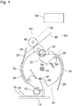
- the sheet flipping device shown in Fig. 1 has a disc-like flipping element 10 that is rotatably mounted on an axis 12 and is disposed near an edge of a sheet receiving surface 14 on which a stack of sheets 16, 18 is to be formed.
- each receiving slot 20, 22 is defined between a part of the peripheral surface of the flipping element 10 and a rigid arm 24 that extends in circumferential direction of the flipping element. Further, each slot 20, 22 has a mouth 26 that is defined between another portion of the peripheral surface of the flipping element 10 and a flexible finger 28 that extends tangentially to the flipping element from a tip of the arm 24.
- Two pushing mechanisms 30, 32 are mounted on the flipping element 10 in diametrically opposite positions, each pushing mechanism being disposed adjacent to an inner end of one of the insertion slots 20, 22.
- Each pushing mechanism 30, 32 has a cam follower 34 that is supported on the flipping element 10 so as to be rotatable about an axis 36.
- Fig. 1 the cam follower 34 of the pushing mechanism 32 is biased into a rest position by a spring 38.
- a friction member 40 in the form of an elastic ring 40 is mounted on the free end of the cam follower so as to project radially outwardly towards the periphery of the flipping member 10.
- a sheet transport device 44 is provided at the periphery of the flipping element 10 in a position opposite to the sheet receiving surface 14.
- the sheet transport device comprises a pair of rollers 46 one of which is drivable for rotation and which form a nip in which a printed sheet 48 is held and conveyed towards the mouth 26 of the sheet insertion slot 20.
- the pair of rollers 46 constitutes the end of a sheet transport path along which printed sheets such as the sheet 48 are discharged one after another from a printer which has not been shown here.
- An electronic controller 50 is provided for controlling rotary drives 52, 54 for the sheet transport device 40 and the flipping element 10.
- the flipping element 10 is held stationary in a position in which the sheet insertion slot 20 assumes a sheet receiving position in which the mouth 26 is opened towards the nip of the pair of rollers 46, so that the leading edge of the sheet 48 may be received in the sheet insertion slot.
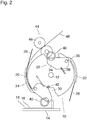
- Fig. 2 shows the device in a later stage in which the flipping element 10 is still in the same position as in Fig. 1 , but the sheet transport device 44 has conveyed the sheet 48 further, so that the leading edge of the sheet has entered into the sheet receiving slot 20.
- the leading edge of the sheet 48 has just reached the bottom of the sheet insertion slot.
- the flipping element 10 may already be rotated anti-clockwise in this stage, but with a peripheral speed that is smaller than the transport speed of the sheet 48, so that the sheet will be pushed deeper into the slot 20.
- Fig. 3 the flipping element 10 is still in the same position as in Figs. 1 and 2 , but the leading edge of the sheet 48 has reached the bottom of the slot 20, and, since the sheet transport device 44 continues to advance the sheet 48, a blouse 56 in the sheet has been formed in the entry part of the mouth 26. This blouse 56 engages the flexible finger 28 and has slightly flexed this finger into an outward direction.
- the speed of the flipping element may be controlled such that no blouse 56 is formed and the leading edge of the sheet 48 just smoothly approaches the bottom of the slot 20.
- the friction element 40 of the pushing mechanism 30 has moved relative to the sheet receiving surface 14 while pressing onto the topmost sheet 18. Due to the rotation of the flipping element 10, the friction element 40 has also moved downward, so that the elastic, annular friction element has been slightly compressed because the cam 42 prevents the cam follower 34 from yielding. At least the outer peripheral surface of the annular friction element 40 has a relatively high frictional coefficient, so that the topmost sheet 18 on the stack has been pushed rightwards in Fig. 4 until its leading edge abuts at a registration wall 58. It is noted that, in the view shown in Fig. 4 , the registration wall 58 (as well as the rollers 46) are disposed in a different plane than the flipping element 10, so that the friction element 40 can move past the registration wall 58 as the rotation of the flipping element continues.
- the blouse 56 in the sheet has grown further, and due to the increased rotary speed of the flipping element 10 and the increased weight of the blouse 56 the leading edge of the sheet 48 is being drawn out of the slot 20.
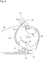
- Fig. 6 the flipping element 10 has been rotated by an angle of 180° relative to the position shown in Fig. 1 , and the rotation has been stopped, so that the insertion slot 22 is now held stationary in the sheet receiving position.
- the cam follower of the pushing device 32 has run onto the cam 42 and has been tilted downwards onto the leading edge of the sheet 48 which has meanwhile dropped out of the insertion slot 20.
- the blouse 56 has become so large that it cannot be entirely shown in Fig. 6 . Still, the trailing edge of the sheet 48 is held in the nip of the rollers 46.
- the flexible finger 28 forming the mouth of the sheet insertion slot 22 cannot yet assume its straight configuration but is flexed radially inwardly by the portion of the sheet 48 that leaves the sheet transport device 44.
- the friction between the sheet and the finger 28 is low, so that no damage will be caused to the sheet 48.
- the sheet 48 will flip over so that it will then lie flat on the receiving surface 14.
- the leading edge of the sheet 48 is still spaced apart from the registration wall 58.
- the flexible finger 48 will instantly flex back into the straight configuration and will form the mouth 26 that is open towards the sheet transport device, so that the leading edge of a new sheet can be inserted. Consequently, no large gap is required between the trailing edge of the sheet 48 and the leading edge of the next sheet.
- the flipping element 10 can be rotated into a sheet receiving position already at a relatively early stage and then wait until the leading edge of the next sheet arrives. Consequently, the timing control for the intermittent rotation of the flipping element 10 is less critical than in conventional devices.
Landscapes
- Engineering & Computer Science (AREA)
- Mechanical Engineering (AREA)
- Discharge By Other Means (AREA)
- Pile Receivers (AREA)
Abstract
Description
- The invention relates to a sheet flipping device comprising:
- a flipping element rotatably disposed adjacent to a sheet receiving plane and having, in its outer periphery, at least two insertion slots for insertion of a respective leading edge of a sheet to be flipped;
- a sheet transport device configured for feeding sheets with their respective leading edges into the insertion slots; and
- a controller configured to control the sheet transport device and a rotary drive for the flipping element such that each sheet the leading edge of which has been inserted into one of the insertion slots is temporarily restrained while the transport mechanism continues to feed the sheet, so that the sheet flips over, and the sheet is then dropped onto the receiving plane.
- An example of a sheet flipping device of this type has been disclosed in
US 9 457 980 B2 - Such sheet flipping devices are employed for example in sheet stackers for stacking printed sheets that are successively discharged from a printing system. The flipping device is provided for flipping each sheet such that a side of the sheet which has been the top side in the sheet transport device will face downwards when the sheet is dropped onto the stack. In known sheet flipping devices, an empty insertion slot can only be brought into a receiving position for receiving a new sheet, when the trailing edge of the previous sheet has left the sheet transport device. Otherwise, a finger that delimits the insertion slot on the outer side would collide with the sheet that is still being fed from the sheet transport device, so that the sheet might be damaged. Consequently, a sufficient gap must be provided between the trailing edge of one sheet and the leading edge of the next sheet, in order for the insertion slot to have sufficient time to reach the sheet receiving position.
- It is an object of the invention to provide a sheet flipping device that is capable of handling sheets that are supplied in close succession.
- In order to achieve this object, according to the invention, the sheet flipping device is characterized in that each insertion slot has a mouth that is defined between a peripheral surface of the flipping element and a flexible finger that extends tangentially from said peripheral surface, the controller is configured to move one of the insertion slots into a sheet receiving position regardless of whether or not a trailing edge of a preceding sheet has left the sheet transport device, and the flexible finger has sufficient flexibility to be deflected by a sheet which has its trailing edge still held in the sheet transport device.
- In the device according to the invention, an empty insertion slot can be moved already into the sheet receiving position before the previous sheet has left the nip of the sheet transport device. The high flexibility of the finger assures that the finger can be deflected by the sheet without causing damage to the sheet. Then, when the trailing edge of the sheet has left the nip, the finger can flex back into its natural position, and the slot is ready to receive the leading edge of the next sheet within an extremely short time. Consequently, the gaps between successive sheets that are being fed to the flipping device can be reduced significantly and, accordingly, the throughput of the flipping device can be increased.
- Another advantage of the invention is that the time interval between the moment at which a sheet clears the insertion slot and is dropped onto the receiving plane and the moment when this slot reaches again the sheet receiving position is no longer dependent upon the length of the sheets. The gaps between successive sheets may fed even be zero
- It is also possible to provide three or more insertion slots on the periphery of the flipping element, so that the throughput can be increased further.
- More specific optional features of the invention are indicated in the dependent claims.
- An embodiment example will now be described in conjunction with the drawings, wherein:
- Fig. 1
- is a schematic view of a sheet flipping device according to the invention; and
- Figs. 2 to 6
- shows the sheet flipping device of
Fig. 1 in a sequence of operational states. - The sheet flipping device shown in
Fig. 1 has a disc-like flipping element 10 that is rotatably mounted on anaxis 12 and is disposed near an edge of asheet receiving surface 14 on which a stack ofsheets - Two
sheet insertion slots element 10 at diametrically opposite positions. An inner portion of eachreceiving slot flipping element 10 and arigid arm 24 that extends in circumferential direction of the flipping element. Further, eachslot mouth 26 that is defined between another portion of the peripheral surface of the flippingelement 10 and aflexible finger 28 that extends tangentially to the flipping element from a tip of thearm 24. - Two
pushing mechanisms element 10 in diametrically opposite positions, each pushing mechanism being disposed adjacent to an inner end of one of theinsertion slots pushing mechanism cam follower 34 that is supported on the flippingelement 10 so as to be rotatable about anaxis 36. - In
Fig. 1 , thecam follower 34 of thepushing mechanism 32 is biased into a rest position by aspring 38. Afriction member 40 in the form of anelastic ring 40 is mounted on the free end of the cam follower so as to project radially outwardly towards the periphery of the flippingmember 10. - In the situation shown in
Fig. 1 , the cam follower of theother pushing mechanism 30 has run onto astationary cam 42 and has thereby been tilted into a working position in which thefriction member 40 projects further out from the periphery of the flipping element and engages thetopmost sheet 18 of the stack formed on thereceiving plane 14. - A
sheet transport device 44 is provided at the periphery of theflipping element 10 in a position opposite to thesheet receiving surface 14. In the example shown, the sheet transport device comprises a pair ofrollers 46 one of which is drivable for rotation and which form a nip in which a printedsheet 48 is held and conveyed towards themouth 26 of thesheet insertion slot 20. - In the given example, the pair of
rollers 46 constitutes the end of a sheet transport path along which printed sheets such as thesheet 48 are discharged one after another from a printer which has not been shown here. - An
electronic controller 50 is provided for controllingrotary drives sheet transport device 40 and theflipping element 10. - In the situation shown in
Fig. 1 , the flippingelement 10 is held stationary in a position in which thesheet insertion slot 20 assumes a sheet receiving position in which themouth 26 is opened towards the nip of the pair ofrollers 46, so that the leading edge of thesheet 48 may be received in the sheet insertion slot. -
Fig. 2 shows the device in a later stage in which theflipping element 10 is still in the same position as inFig. 1 , but thesheet transport device 44 has conveyed thesheet 48 further, so that the leading edge of the sheet has entered into thesheet receiving slot 20. In the situation shown inFig. 2 , the leading edge of thesheet 48 has just reached the bottom of the sheet insertion slot. Optionally, theflipping element 10 may already be rotated anti-clockwise in this stage, but with a peripheral speed that is smaller than the transport speed of thesheet 48, so that the sheet will be pushed deeper into theslot 20. - In
Fig. 3 , theflipping element 10 is still in the same position as inFigs. 1 and2 , but the leading edge of thesheet 48 has reached the bottom of theslot 20, and, since thesheet transport device 44 continues to advance thesheet 48, ablouse 56 in the sheet has been formed in the entry part of themouth 26. Thisblouse 56 engages theflexible finger 28 and has slightly flexed this finger into an outward direction. - In the above-mentioned alternative embodiment in which the flipping
element 10 is rotated already in this stage, the speed of the flipping element may be controlled such that noblouse 56 is formed and the leading edge of thesheet 48 just smoothly approaches the bottom of theslot 20. - In the situation shown in
Fig. 4 , the flippingelement 10 has been rotated by a small angle, but the peripheral speed is still smaller than the transport speed of thesheet 48, so that theblouse 56 has grown. - The
friction element 40 of thepushing mechanism 30 has moved relative to thesheet receiving surface 14 while pressing onto thetopmost sheet 18. Due to the rotation of the flippingelement 10, thefriction element 40 has also moved downward, so that the elastic, annular friction element has been slightly compressed because thecam 42 prevents thecam follower 34 from yielding. At least the outer peripheral surface of theannular friction element 40 has a relatively high frictional coefficient, so that thetopmost sheet 18 on the stack has been pushed rightwards inFig. 4 until its leading edge abuts at aregistration wall 58. It is noted that, in the view shown inFig. 4 , the registration wall 58 (as well as the rollers 46) are disposed in a different plane than the flippingelement 10, so that thefriction element 40 can move past theregistration wall 58 as the rotation of the flipping element continues. - In
Fig. 5 , the rotation of the flippingelement 10 has accelerated and the flipping element has been turned by about 45°. Thecam follower 34 of the pushingdevice 30 has cleared thecam 42, so that thespring 38 has drawn the cam follower back into the rest position. Meanwhile, theinsertion slot 22 approaches the sheet receiving position where a new sheet can be inserted. It is noted however that thesheet 48 has not yet cleared thesheet transport device 44. - The
blouse 56 in the sheet has grown further, and due to the increased rotary speed of the flippingelement 10 and the increased weight of theblouse 56 the leading edge of thesheet 48 is being drawn out of theslot 20. - In
Fig. 6 , theflipping element 10 has been rotated by an angle of 180° relative to the position shown inFig. 1 , and the rotation has been stopped, so that theinsertion slot 22 is now held stationary in the sheet receiving position. The cam follower of the pushingdevice 32 has run onto thecam 42 and has been tilted downwards onto the leading edge of thesheet 48 which has meanwhile dropped out of theinsertion slot 20. Theblouse 56 has become so large that it cannot be entirely shown inFig. 6 . Still, the trailing edge of thesheet 48 is held in the nip of therollers 46. For this reason, theflexible finger 28 forming the mouth of thesheet insertion slot 22 cannot yet assume its straight configuration but is flexed radially inwardly by the portion of thesheet 48 that leaves thesheet transport device 44. The friction between the sheet and thefinger 28 is low, so that no damage will be caused to thesheet 48. As soon as the trailing edge of thesheet 48 has left the nip of therollers 46, thesheet 48 will flip over so that it will then lie flat on thereceiving surface 14. However, the leading edge of thesheet 48 is still spaced apart from theregistration wall 58. - As soon as the trailing edge of the
sheet 48 has cleared the nip of therollers 46, theflexible finger 48 will instantly flex back into the straight configuration and will form themouth 26 that is open towards the sheet transport device, so that the leading edge of a new sheet can be inserted. Consequently, no large gap is required between the trailing edge of thesheet 48 and the leading edge of the next sheet. - As soon as the new sheet has been inserted into the
slot 22 and has reached the condition shown inFig. 3 , the rotation of the flippingelement 10 will be resumed and thefriction element 40 of the pushingdevice 32 will push the leading edge of thesheet 48 against theregistration wall 58. - Due to the flexibility of the
fingers 28, the flippingelement 10 can be rotated into a sheet receiving position already at a relatively early stage and then wait until the leading edge of the next sheet arrives. Consequently, the timing control for the intermittent rotation of the flippingelement 10 is less critical than in conventional devices.
Claims (5)
- A sheet flipping device comprising:- a flipping element (10) rotatably disposed adjacent to a sheet receiving plane (14) and having, in its outer periphery, at least two insertion slots (20, 22) for insertion of a respective leading edge of a sheet (48) to be flipped;- a sheet transport device (44) configured for feeding sheets with their respective leading edges into the insertion slots (20, 22); and- a controller (50) configured to control the sheet transport device (44) and a rotary drive (54) for the flipping element (10) such that each sheet the leading edge of which has been inserted into one of the insertion slots (20, 22) is temporarily restrained while the transport mechanism (44) continues to feed the sheet, so that the sheet flips over, and the sheet is then dropped onto the receiving plane (14),
characterized in that each insertion slot (20, 22) has a mouth (26) defined between a peripheral surface of the flipping element (10) and a flexible finger (28) that extends tangentially from said peripheral surface, the controller (50) is configured to move one of the insertion slots (20, 22) into a sheet receiving position regardless of whether or not a trailing edge of a preceding sheet has left the sheet transport device, and the flexible finger (28) has sufficient flexibility to be deflected by a sheet which has its trailing edge still held in the sheet transport device (44). - The sheet flipping device according to claim 1, wherein the flipping element (10) has two insertion slots (20, 22) with a mutual angular spacing of 180°.
- The sheet flipping device according to claim 1 or 2, wherein each insertion slot (20, 22) has an inner portion that is outwardly delimited by a rigid arm (24) of the flipping element (10), and the flexible finger (18) projects from a free end of said arm (24).
- The sheet flipping device according to any of the preceding claims, wherein the flipping element (10) has, for each insertion slot (22), a pushing mechanism (30, 32) arranged to engage a sheet (18) that has been dropped onto the receiving surface (14) and then to push this sheet against a registration wall (58) as the flipping element (10) rotates.
- A software product comprising computer-readable program code that, when loaded into a controller (50) of a sheet flipping device according to any of the preceding claims, causes the controller to operate as specified in claim 1.
Priority Applications (2)
| Application Number | Priority Date | Filing Date | Title |
|---|---|---|---|
| EP20170437.6A EP3901073B1 (en) | 2020-04-20 | 2020-04-20 | A sheet flipping device |
| US17/224,387 US20210323783A1 (en) | 2020-04-20 | 2021-04-07 | Sheet flipping device |
Applications Claiming Priority (1)
| Application Number | Priority Date | Filing Date | Title |
|---|---|---|---|
| EP20170437.6A EP3901073B1 (en) | 2020-04-20 | 2020-04-20 | A sheet flipping device |
Publications (3)
| Publication Number | Publication Date |
|---|---|
| EP3901073A1 true EP3901073A1 (en) | 2021-10-27 |
| EP3901073C0 EP3901073C0 (en) | 2023-11-22 |
| EP3901073B1 EP3901073B1 (en) | 2023-11-22 |
Family
ID=70390772
Family Applications (1)
| Application Number | Title | Priority Date | Filing Date |
|---|---|---|---|
| EP20170437.6A Active EP3901073B1 (en) | 2020-04-20 | 2020-04-20 | A sheet flipping device |
Country Status (2)
| Country | Link |
|---|---|
| US (1) | US20210323783A1 (en) |
| EP (1) | EP3901073B1 (en) |
Citations (3)
| Publication number | Priority date | Publication date | Assignee | Title |
|---|---|---|---|---|
| US4228997A (en) * | 1978-06-23 | 1980-10-21 | Eastman Kodak Company | Stacking machine |
| US20050280198A1 (en) * | 2004-06-21 | 2005-12-22 | Eastman Kodak Company | Devices and methods for flipping a sheet with blowing assistance |
| US9457980B2 (en) | 2011-11-09 | 2016-10-04 | Oce-Technologies B.V. | Sheet stacking device |
Family Cites Families (7)
| Publication number | Priority date | Publication date | Assignee | Title |
|---|---|---|---|---|
| US3487447A (en) * | 1968-05-03 | 1969-12-30 | Talcott Inc James | Delivery mechanism for rotary printing press |
| US4385756A (en) * | 1980-08-29 | 1983-05-31 | Xerox Corporation | Sheet inverting and stacking apparatus |
| US4431177A (en) * | 1980-08-29 | 1984-02-14 | Xerox Corporation | Sheet offsetting and registering apparatus |
| US4469320A (en) * | 1982-05-03 | 1984-09-04 | Xerox Corporation | Dual mode stack sensor |
| US4615518A (en) * | 1982-12-14 | 1986-10-07 | Brandt, Incorporated | Document handling and counting apparatus |
| US4589645A (en) * | 1985-10-03 | 1986-05-20 | Xerox Corporation | Document set separator and stack height sensor |
| US5098080A (en) * | 1990-12-19 | 1992-03-24 | Xerox Corporation | Ski jump stack height sensor |
-
2020
- 2020-04-20 EP EP20170437.6A patent/EP3901073B1/en active Active
-
2021
- 2021-04-07 US US17/224,387 patent/US20210323783A1/en not_active Abandoned
Patent Citations (3)
| Publication number | Priority date | Publication date | Assignee | Title |
|---|---|---|---|---|
| US4228997A (en) * | 1978-06-23 | 1980-10-21 | Eastman Kodak Company | Stacking machine |
| US20050280198A1 (en) * | 2004-06-21 | 2005-12-22 | Eastman Kodak Company | Devices and methods for flipping a sheet with blowing assistance |
| US9457980B2 (en) | 2011-11-09 | 2016-10-04 | Oce-Technologies B.V. | Sheet stacking device |
Also Published As
| Publication number | Publication date |
|---|---|
| EP3901073C0 (en) | 2023-11-22 |
| US20210323783A1 (en) | 2021-10-21 |
| EP3901073B1 (en) | 2023-11-22 |
Similar Documents
| Publication | Publication Date | Title |
|---|---|---|
| CA1204798A (en) | Orbital feeder | |
| US4596545A (en) | Orbital feeder | |
| US4299378A (en) | Apparatus for singularizing and opening stacked folded sheets | |
| US5653327A (en) | Inserter device and a method for transposing a stream of products using the same | |
| US4228997A (en) | Stacking machine | |
| EP2548827B1 (en) | Method for feeding inserts by a rotary gripper system comprising synchronied initialization. | |
| US3127167A (en) | Sheet stacker or feeder | |
| US5374053A (en) | Device for changing the transport position of products | |
| US20030102617A1 (en) | Single/double sheet stacker | |
| US6623000B2 (en) | Apparatus and method for separating sheet material by means of a reciprocating disk separator | |
| US5174559A (en) | Sheet material handling apparatus and method using a skewed sheet stack and an alignment mechanism | |
| US5169285A (en) | Apparatus for singularizing stacked sheets of paper and the like | |
| US3861667A (en) | Apparatus for picking up and feeding individual sheets from a stack of sheets | |
| EP3901073B1 (en) | A sheet flipping device | |
| US6196538B1 (en) | Apparatus for processing flexible, sheet-like products | |
| EP0329597A1 (en) | Paper feeding apparatus | |
| US3266796A (en) | Document handling apparatus | |
| US6663104B2 (en) | Method and system for aligning moving sheets | |
| US8925291B2 (en) | Device for inserting sheets into an envelope | |
| US3602495A (en) | Device for the removal of sheets,inserts or the like released from a roller frame | |
| US6264193B1 (en) | Document conveyance system for conveying single documents | |
| JPH1087137A (en) | Method and device to carry flat printed matter | |
| US8033539B2 (en) | Pressdown cam for post processing device | |
| US20080018043A1 (en) | Sheet material feeder | |
| JPH1045306A (en) | Device for carrying printed product to another processing place |
Legal Events
| Date | Code | Title | Description |
|---|---|---|---|
| PUAI | Public reference made under article 153(3) epc to a published international application that has entered the european phase |
Free format text: ORIGINAL CODE: 0009012 |
|
| STAA | Information on the status of an ep patent application or granted ep patent |
Free format text: STATUS: THE APPLICATION HAS BEEN PUBLISHED |
|
| AK | Designated contracting states |
Kind code of ref document: A1 Designated state(s): AL AT BE BG CH CY CZ DE DK EE ES FI FR GB GR HR HU IE IS IT LI LT LU LV MC MK MT NL NO PL PT RO RS SE SI SK SM TR |
|
| B565 | Issuance of search results under rule 164(2) epc |
Effective date: 20201021 |
|
| STAA | Information on the status of an ep patent application or granted ep patent |
Free format text: STATUS: REQUEST FOR EXAMINATION WAS MADE |
|
| 17P | Request for examination filed |
Effective date: 20220428 |
|
| RBV | Designated contracting states (corrected) |
Designated state(s): AL AT BE BG CH CY CZ DE DK EE ES FI FR GB GR HR HU IE IS IT LI LT LU LV MC MK MT NL NO PL PT RO RS SE SI SK SM TR |
|
| GRAP | Despatch of communication of intention to grant a patent |
Free format text: ORIGINAL CODE: EPIDOSNIGR1 |
|
| STAA | Information on the status of an ep patent application or granted ep patent |
Free format text: STATUS: GRANT OF PATENT IS INTENDED |
|
| RIC1 | Information provided on ipc code assigned before grant |
Ipc: B65H 31/36 20060101ALI20230525BHEP Ipc: B65H 29/12 20060101ALI20230525BHEP Ipc: B65H 29/40 20060101AFI20230525BHEP |
|
| INTG | Intention to grant announced |
Effective date: 20230627 |
|
| GRAS | Grant fee paid |
Free format text: ORIGINAL CODE: EPIDOSNIGR3 |
|
| GRAA | (expected) grant |
Free format text: ORIGINAL CODE: 0009210 |
|
| STAA | Information on the status of an ep patent application or granted ep patent |
Free format text: STATUS: THE PATENT HAS BEEN GRANTED |
|
| AK | Designated contracting states |
Kind code of ref document: B1 Designated state(s): AL AT BE BG CH CY CZ DE DK EE ES FI FR GB GR HR HU IE IS IT LI LT LU LV MC MK MT NL NO PL PT RO RS SE SI SK SM TR |
|
| REG | Reference to a national code |
Ref country code: GB Ref legal event code: FG4D |
|
| REG | Reference to a national code |
Ref country code: CH Ref legal event code: EP |
|
| REG | Reference to a national code |
Ref country code: DE Ref legal event code: R096 Ref document number: 602020021344 Country of ref document: DE |
|
| REG | Reference to a national code |
Ref country code: IE Ref legal event code: FG4D |
|
| U01 | Request for unitary effect filed |
Effective date: 20231208 |
|
| U07 | Unitary effect registered |
Designated state(s): AT BE BG DE DK EE FI FR IT LT LU LV MT NL PT SE SI Effective date: 20231215 |
|
| PG25 | Lapsed in a contracting state [announced via postgrant information from national office to epo] |
Ref country code: GR Free format text: LAPSE BECAUSE OF FAILURE TO SUBMIT A TRANSLATION OF THE DESCRIPTION OR TO PAY THE FEE WITHIN THE PRESCRIBED TIME-LIMIT Effective date: 20240223 |
|
| PG25 | Lapsed in a contracting state [announced via postgrant information from national office to epo] |
Ref country code: IS Free format text: LAPSE BECAUSE OF FAILURE TO SUBMIT A TRANSLATION OF THE DESCRIPTION OR TO PAY THE FEE WITHIN THE PRESCRIBED TIME-LIMIT Effective date: 20240322 |
|
| PG25 | Lapsed in a contracting state [announced via postgrant information from national office to epo] |
Ref country code: ES Free format text: LAPSE BECAUSE OF FAILURE TO SUBMIT A TRANSLATION OF THE DESCRIPTION OR TO PAY THE FEE WITHIN THE PRESCRIBED TIME-LIMIT Effective date: 20231122 |
|
| PG25 | Lapsed in a contracting state [announced via postgrant information from national office to epo] |
Ref country code: IS Free format text: LAPSE BECAUSE OF FAILURE TO SUBMIT A TRANSLATION OF THE DESCRIPTION OR TO PAY THE FEE WITHIN THE PRESCRIBED TIME-LIMIT Effective date: 20240322 Ref country code: GR Free format text: LAPSE BECAUSE OF FAILURE TO SUBMIT A TRANSLATION OF THE DESCRIPTION OR TO PAY THE FEE WITHIN THE PRESCRIBED TIME-LIMIT Effective date: 20240223 Ref country code: ES Free format text: LAPSE BECAUSE OF FAILURE TO SUBMIT A TRANSLATION OF THE DESCRIPTION OR TO PAY THE FEE WITHIN THE PRESCRIBED TIME-LIMIT Effective date: 20231122 |
|
| PG25 | Lapsed in a contracting state [announced via postgrant information from national office to epo] |
Ref country code: RS Free format text: LAPSE BECAUSE OF FAILURE TO SUBMIT A TRANSLATION OF THE DESCRIPTION OR TO PAY THE FEE WITHIN THE PRESCRIBED TIME-LIMIT Effective date: 20231122 Ref country code: PL Free format text: LAPSE BECAUSE OF FAILURE TO SUBMIT A TRANSLATION OF THE DESCRIPTION OR TO PAY THE FEE WITHIN THE PRESCRIBED TIME-LIMIT Effective date: 20231122 Ref country code: NO Free format text: LAPSE BECAUSE OF FAILURE TO SUBMIT A TRANSLATION OF THE DESCRIPTION OR TO PAY THE FEE WITHIN THE PRESCRIBED TIME-LIMIT Effective date: 20240222 Ref country code: HR Free format text: LAPSE BECAUSE OF FAILURE TO SUBMIT A TRANSLATION OF THE DESCRIPTION OR TO PAY THE FEE WITHIN THE PRESCRIBED TIME-LIMIT Effective date: 20231122 |
|
| U20 | Renewal fee for the european patent with unitary effect paid |
Year of fee payment: 5 Effective date: 20240430 |
|
| PG25 | Lapsed in a contracting state [announced via postgrant information from national office to epo] |
Ref country code: CZ Free format text: LAPSE BECAUSE OF FAILURE TO SUBMIT A TRANSLATION OF THE DESCRIPTION OR TO PAY THE FEE WITHIN THE PRESCRIBED TIME-LIMIT Effective date: 20231122 |
|
| PG25 | Lapsed in a contracting state [announced via postgrant information from national office to epo] |
Ref country code: SK Free format text: LAPSE BECAUSE OF FAILURE TO SUBMIT A TRANSLATION OF THE DESCRIPTION OR TO PAY THE FEE WITHIN THE PRESCRIBED TIME-LIMIT Effective date: 20231122 |
|
| PG25 | Lapsed in a contracting state [announced via postgrant information from national office to epo] |
Ref country code: SM Free format text: LAPSE BECAUSE OF FAILURE TO SUBMIT A TRANSLATION OF THE DESCRIPTION OR TO PAY THE FEE WITHIN THE PRESCRIBED TIME-LIMIT Effective date: 20231122 Ref country code: SK Free format text: LAPSE BECAUSE OF FAILURE TO SUBMIT A TRANSLATION OF THE DESCRIPTION OR TO PAY THE FEE WITHIN THE PRESCRIBED TIME-LIMIT Effective date: 20231122 Ref country code: RO Free format text: LAPSE BECAUSE OF FAILURE TO SUBMIT A TRANSLATION OF THE DESCRIPTION OR TO PAY THE FEE WITHIN THE PRESCRIBED TIME-LIMIT Effective date: 20231122 Ref country code: CZ Free format text: LAPSE BECAUSE OF FAILURE TO SUBMIT A TRANSLATION OF THE DESCRIPTION OR TO PAY THE FEE WITHIN THE PRESCRIBED TIME-LIMIT Effective date: 20231122 |
|
| REG | Reference to a national code |
Ref country code: DE Ref legal event code: R097 Ref document number: 602020021344 Country of ref document: DE |
|
| PLBE | No opposition filed within time limit |
Free format text: ORIGINAL CODE: 0009261 |
|
| STAA | Information on the status of an ep patent application or granted ep patent |
Free format text: STATUS: NO OPPOSITION FILED WITHIN TIME LIMIT |
|
| 26N | No opposition filed |
Effective date: 20240823 |
|
| PG25 | Lapsed in a contracting state [announced via postgrant information from national office to epo] |
Ref country code: MC Free format text: LAPSE BECAUSE OF FAILURE TO SUBMIT A TRANSLATION OF THE DESCRIPTION OR TO PAY THE FEE WITHIN THE PRESCRIBED TIME-LIMIT Effective date: 20231122 |
|
| PG25 | Lapsed in a contracting state [announced via postgrant information from national office to epo] |
Ref country code: MC Free format text: LAPSE BECAUSE OF FAILURE TO SUBMIT A TRANSLATION OF THE DESCRIPTION OR TO PAY THE FEE WITHIN THE PRESCRIBED TIME-LIMIT Effective date: 20231122 |
|
| REG | Reference to a national code |
Ref country code: CH Ref legal event code: PL |
|
| GBPC | Gb: european patent ceased through non-payment of renewal fee |
Effective date: 20240420 |
|
| PG25 | Lapsed in a contracting state [announced via postgrant information from national office to epo] |
Ref country code: GB Free format text: LAPSE BECAUSE OF NON-PAYMENT OF DUE FEES Effective date: 20240420 |
|
| PG25 | Lapsed in a contracting state [announced via postgrant information from national office to epo] |
Ref country code: GB Free format text: LAPSE BECAUSE OF NON-PAYMENT OF DUE FEES Effective date: 20240420 Ref country code: CH Free format text: LAPSE BECAUSE OF NON-PAYMENT OF DUE FEES Effective date: 20240430 |
|
| PG25 | Lapsed in a contracting state [announced via postgrant information from national office to epo] |
Ref country code: IE Free format text: LAPSE BECAUSE OF NON-PAYMENT OF DUE FEES Effective date: 20240420 |
|
| U20 | Renewal fee for the european patent with unitary effect paid |
Year of fee payment: 6 Effective date: 20250430 |
|
| PG25 | Lapsed in a contracting state [announced via postgrant information from national office to epo] |
Ref country code: CY Free format text: LAPSE BECAUSE OF FAILURE TO SUBMIT A TRANSLATION OF THE DESCRIPTION OR TO PAY THE FEE WITHIN THE PRESCRIBED TIME-LIMIT; INVALID AB INITIO Effective date: 20200420 |
|
| PG25 | Lapsed in a contracting state [announced via postgrant information from national office to epo] |
Ref country code: HU Free format text: LAPSE BECAUSE OF FAILURE TO SUBMIT A TRANSLATION OF THE DESCRIPTION OR TO PAY THE FEE WITHIN THE PRESCRIBED TIME-LIMIT; INVALID AB INITIO Effective date: 20200420 |