EP3901037A1 - Water supply system for aircraft - Google Patents
Water supply system for aircraft Download PDFInfo
- Publication number
- EP3901037A1 EP3901037A1 EP19899893.2A EP19899893A EP3901037A1 EP 3901037 A1 EP3901037 A1 EP 3901037A1 EP 19899893 A EP19899893 A EP 19899893A EP 3901037 A1 EP3901037 A1 EP 3901037A1
- Authority
- EP
- European Patent Office
- Prior art keywords
- water
- water supply
- aircraft
- tank
- outlets
- Prior art date
- Legal status (The legal status is an assumption and is not a legal conclusion. Google has not performed a legal analysis and makes no representation as to the accuracy of the status listed.)
- Granted
Links
Images
Classifications
-
- C—CHEMISTRY; METALLURGY
- C02—TREATMENT OF WATER, WASTE WATER, SEWAGE, OR SLUDGE
- C02F—TREATMENT OF WATER, WASTE WATER, SEWAGE, OR SLUDGE
- C02F9/00—Multistage treatment of water, waste water or sewage
-
- E—FIXED CONSTRUCTIONS
- E03—WATER SUPPLY; SEWERAGE
- E03C—DOMESTIC PLUMBING INSTALLATIONS FOR FRESH WATER OR WASTE WATER; SINKS
- E03C1/00—Domestic plumbing installations for fresh water or waste water; Sinks
- E03C1/02—Plumbing installations for fresh water
- E03C1/10—Devices for preventing contamination of drinking-water pipes, e.g. means for aerating self-closing flushing valves
-
- A—HUMAN NECESSITIES
- A61—MEDICAL OR VETERINARY SCIENCE; HYGIENE
- A61L—METHODS OR APPARATUS FOR STERILISING MATERIALS OR OBJECTS IN GENERAL; DISINFECTION, STERILISATION OR DEODORISATION OF AIR; CHEMICAL ASPECTS OF BANDAGES, DRESSINGS, ABSORBENT PADS OR SURGICAL ARTICLES; MATERIALS FOR BANDAGES, DRESSINGS, ABSORBENT PADS OR SURGICAL ARTICLES
- A61L2/00—Disinfection or sterilisation of materials or objects, in general; Accessories therefor
- A61L2/02—Disinfection or sterilisation of materials or objects, in general; Accessories therefor using physical processes
- A61L2/08—Radiation
- A61L2/10—Ultraviolet [UV] radiation
-
- A—HUMAN NECESSITIES
- A61—MEDICAL OR VETERINARY SCIENCE; HYGIENE
- A61L—METHODS OR APPARATUS FOR STERILISING MATERIALS OR OBJECTS IN GENERAL; DISINFECTION, STERILISATION OR DEODORISATION OF AIR; CHEMICAL ASPECTS OF BANDAGES, DRESSINGS, ABSORBENT PADS OR SURGICAL ARTICLES; MATERIALS FOR BANDAGES, DRESSINGS, ABSORBENT PADS OR SURGICAL ARTICLES
- A61L2/00—Disinfection or sterilisation of materials or objects, in general; Accessories therefor
- A61L2/16—Disinfection or sterilisation of materials or objects, in general; Accessories therefor using chemical substances
- A61L2/18—Liquid substances
- A61L2/183—Ozone dissolved in a liquid
-
- A—HUMAN NECESSITIES
- A61—MEDICAL OR VETERINARY SCIENCE; HYGIENE
- A61L—METHODS OR APPARATUS FOR STERILISING MATERIALS OR OBJECTS IN GENERAL; DISINFECTION, STERILISATION OR DEODORISATION OF AIR; CHEMICAL ASPECTS OF BANDAGES, DRESSINGS, ABSORBENT PADS OR SURGICAL ARTICLES; MATERIALS FOR BANDAGES, DRESSINGS, ABSORBENT PADS OR SURGICAL ARTICLES
- A61L2/00—Disinfection or sterilisation of materials or objects, in general; Accessories therefor
- A61L2/26—Accessories
-
- B—PERFORMING OPERATIONS; TRANSPORTING
- B64—AIRCRAFT; AVIATION; COSMONAUTICS
- B64D—EQUIPMENT FOR FITTING IN OR TO AIRCRAFT; FLIGHT SUITS; PARACHUTES; ARRANGEMENT OR MOUNTING OF POWER PLANTS OR PROPULSION TRANSMISSIONS IN AIRCRAFT
- B64D11/00—Passenger or crew accommodation; Flight-deck installations not otherwise provided for
- B64D11/02—Toilet fittings
-
- C—CHEMISTRY; METALLURGY
- C02—TREATMENT OF WATER, WASTE WATER, SEWAGE, OR SLUDGE
- C02F—TREATMENT OF WATER, WASTE WATER, SEWAGE, OR SLUDGE
- C02F1/00—Treatment of water, waste water, or sewage
- C02F1/006—Water distributors either inside a treatment tank or directing the water to several treatment tanks; Water treatment plants incorporating these distributors, with or without chemical or biological tanks
-
- E—FIXED CONSTRUCTIONS
- E03—WATER SUPPLY; SEWERAGE
- E03D—WATER-CLOSETS OR URINALS WITH FLUSHING DEVICES; FLUSHING VALVES THEREFOR
- E03D9/00—Sanitary or other accessories for lavatories ; Devices for cleaning or disinfecting the toilet room or the toilet bowl; Devices for eliminating smells
- E03D9/02—Devices adding a disinfecting, deodorising, or cleaning agent to the water while flushing
-
- A—HUMAN NECESSITIES
- A61—MEDICAL OR VETERINARY SCIENCE; HYGIENE
- A61L—METHODS OR APPARATUS FOR STERILISING MATERIALS OR OBJECTS IN GENERAL; DISINFECTION, STERILISATION OR DEODORISATION OF AIR; CHEMICAL ASPECTS OF BANDAGES, DRESSINGS, ABSORBENT PADS OR SURGICAL ARTICLES; MATERIALS FOR BANDAGES, DRESSINGS, ABSORBENT PADS OR SURGICAL ARTICLES
- A61L2101/00—Chemical composition of materials used in disinfecting, sterilising or deodorising
- A61L2101/02—Inorganic materials
-
- A—HUMAN NECESSITIES
- A61—MEDICAL OR VETERINARY SCIENCE; HYGIENE
- A61L—METHODS OR APPARATUS FOR STERILISING MATERIALS OR OBJECTS IN GENERAL; DISINFECTION, STERILISATION OR DEODORISATION OF AIR; CHEMICAL ASPECTS OF BANDAGES, DRESSINGS, ABSORBENT PADS OR SURGICAL ARTICLES; MATERIALS FOR BANDAGES, DRESSINGS, ABSORBENT PADS OR SURGICAL ARTICLES
- A61L2202/00—Aspects relating to methods or apparatus for disinfecting or sterilising materials or objects
- A61L2202/10—Apparatus features
- A61L2202/11—Apparatus for generating biocidal substances, e.g. vaporisers, UV lamps
-
- A—HUMAN NECESSITIES
- A61—MEDICAL OR VETERINARY SCIENCE; HYGIENE
- A61L—METHODS OR APPARATUS FOR STERILISING MATERIALS OR OBJECTS IN GENERAL; DISINFECTION, STERILISATION OR DEODORISATION OF AIR; CHEMICAL ASPECTS OF BANDAGES, DRESSINGS, ABSORBENT PADS OR SURGICAL ARTICLES; MATERIALS FOR BANDAGES, DRESSINGS, ABSORBENT PADS OR SURGICAL ARTICLES
- A61L2202/00—Aspects relating to methods or apparatus for disinfecting or sterilising materials or objects
- A61L2202/10—Apparatus features
- A61L2202/17—Combination with washing or cleaning means
-
- C—CHEMISTRY; METALLURGY
- C02—TREATMENT OF WATER, WASTE WATER, SEWAGE, OR SLUDGE
- C02F—TREATMENT OF WATER, WASTE WATER, SEWAGE, OR SLUDGE
- C02F1/00—Treatment of water, waste water, or sewage
- C02F1/001—Processes for the treatment of water whereby the filtration technique is of importance
-
- C—CHEMISTRY; METALLURGY
- C02—TREATMENT OF WATER, WASTE WATER, SEWAGE, OR SLUDGE
- C02F—TREATMENT OF WATER, WASTE WATER, SEWAGE, OR SLUDGE
- C02F1/00—Treatment of water, waste water, or sewage
- C02F1/30—Treatment of water, waste water, or sewage by irradiation
- C02F1/32—Treatment of water, waste water, or sewage by irradiation with ultraviolet light
-
- C—CHEMISTRY; METALLURGY
- C02—TREATMENT OF WATER, WASTE WATER, SEWAGE, OR SLUDGE
- C02F—TREATMENT OF WATER, WASTE WATER, SEWAGE, OR SLUDGE
- C02F1/00—Treatment of water, waste water, or sewage
- C02F1/30—Treatment of water, waste water, or sewage by irradiation
- C02F1/32—Treatment of water, waste water, or sewage by irradiation with ultraviolet light
- C02F1/325—Irradiation devices or lamp constructions
-
- C—CHEMISTRY; METALLURGY
- C02—TREATMENT OF WATER, WASTE WATER, SEWAGE, OR SLUDGE
- C02F—TREATMENT OF WATER, WASTE WATER, SEWAGE, OR SLUDGE
- C02F1/00—Treatment of water, waste water, or sewage
- C02F1/72—Treatment of water, waste water, or sewage by oxidation
- C02F1/78—Treatment of water, waste water, or sewage by oxidation with ozone
-
- C—CHEMISTRY; METALLURGY
- C02—TREATMENT OF WATER, WASTE WATER, SEWAGE, OR SLUDGE
- C02F—TREATMENT OF WATER, WASTE WATER, SEWAGE, OR SLUDGE
- C02F2201/00—Apparatus for treatment of water, waste water or sewage
- C02F2201/001—Build in apparatus for autonomous on board water supply and wastewater treatment (e.g. for aircrafts, cruiseships, oil drilling platforms, railway trains, space stations)
-
- C—CHEMISTRY; METALLURGY
- C02—TREATMENT OF WATER, WASTE WATER, SEWAGE, OR SLUDGE
- C02F—TREATMENT OF WATER, WASTE WATER, SEWAGE, OR SLUDGE
- C02F2201/00—Apparatus for treatment of water, waste water or sewage
- C02F2201/009—Apparatus with independent power supply, e.g. solar cells, windpower or fuel cells
-
- C—CHEMISTRY; METALLURGY
- C02—TREATMENT OF WATER, WASTE WATER, SEWAGE, OR SLUDGE
- C02F—TREATMENT OF WATER, WASTE WATER, SEWAGE, OR SLUDGE
- C02F2201/00—Apparatus for treatment of water, waste water or sewage
- C02F2201/32—Details relating to UV-irradiation devices
- C02F2201/322—Lamp arrangement
- C02F2201/3222—Units using UV-light emitting diodes [LED]
-
- C—CHEMISTRY; METALLURGY
- C02—TREATMENT OF WATER, WASTE WATER, SEWAGE, OR SLUDGE
- C02F—TREATMENT OF WATER, WASTE WATER, SEWAGE, OR SLUDGE
- C02F2201/00—Apparatus for treatment of water, waste water or sewage
- C02F2201/32—Details relating to UV-irradiation devices
- C02F2201/322—Lamp arrangement
- C02F2201/3227—Units with two or more lamps
-
- C—CHEMISTRY; METALLURGY
- C02—TREATMENT OF WATER, WASTE WATER, SEWAGE, OR SLUDGE
- C02F—TREATMENT OF WATER, WASTE WATER, SEWAGE, OR SLUDGE
- C02F2201/00—Apparatus for treatment of water, waste water or sewage
- C02F2201/32—Details relating to UV-irradiation devices
- C02F2201/322—Lamp arrangement
- C02F2201/3228—Units having reflectors, e.g. coatings, baffles, plates, mirrors
-
- C—CHEMISTRY; METALLURGY
- C02—TREATMENT OF WATER, WASTE WATER, SEWAGE, OR SLUDGE
- C02F—TREATMENT OF WATER, WASTE WATER, SEWAGE, OR SLUDGE
- C02F2201/00—Apparatus for treatment of water, waste water or sewage
- C02F2201/78—Details relating to ozone treatment devices
- C02F2201/782—Ozone generators
-
- C—CHEMISTRY; METALLURGY
- C02—TREATMENT OF WATER, WASTE WATER, SEWAGE, OR SLUDGE
- C02F—TREATMENT OF WATER, WASTE WATER, SEWAGE, OR SLUDGE
- C02F2303/00—Specific treatment goals
- C02F2303/04—Disinfection
-
- C—CHEMISTRY; METALLURGY
- C02—TREATMENT OF WATER, WASTE WATER, SEWAGE, OR SLUDGE
- C02F—TREATMENT OF WATER, WASTE WATER, SEWAGE, OR SLUDGE
- C02F2305/00—Use of specific compounds during water treatment
- C02F2305/02—Specific form of oxidant
- C02F2305/023—Reactive oxygen species, singlet oxygen, OH radical
-
- E—FIXED CONSTRUCTIONS
- E03—WATER SUPPLY; SEWERAGE
- E03C—DOMESTIC PLUMBING INSTALLATIONS FOR FRESH WATER OR WASTE WATER; SINKS
- E03C2201/00—Details, devices or methods not otherwise provided for
- E03C2201/40—Arrangement of water treatment devices in domestic plumbing installations
-
- Y—GENERAL TAGGING OF NEW TECHNOLOGICAL DEVELOPMENTS; GENERAL TAGGING OF CROSS-SECTIONAL TECHNOLOGIES SPANNING OVER SEVERAL SECTIONS OF THE IPC; TECHNICAL SUBJECTS COVERED BY FORMER USPC CROSS-REFERENCE ART COLLECTIONS [XRACs] AND DIGESTS
- Y02—TECHNOLOGIES OR APPLICATIONS FOR MITIGATION OR ADAPTATION AGAINST CLIMATE CHANGE
- Y02A—TECHNOLOGIES FOR ADAPTATION TO CLIMATE CHANGE
- Y02A20/00—Water conservation; Efficient water supply; Efficient water use
- Y02A20/20—Controlling water pollution; Waste water treatment
- Y02A20/208—Off-grid powered water treatment
- Y02A20/211—Solar-powered water purification
-
- Y—GENERAL TAGGING OF NEW TECHNOLOGICAL DEVELOPMENTS; GENERAL TAGGING OF CROSS-SECTIONAL TECHNOLOGIES SPANNING OVER SEVERAL SECTIONS OF THE IPC; TECHNICAL SUBJECTS COVERED BY FORMER USPC CROSS-REFERENCE ART COLLECTIONS [XRACs] AND DIGESTS
- Y02—TECHNOLOGIES OR APPLICATIONS FOR MITIGATION OR ADAPTATION AGAINST CLIMATE CHANGE
- Y02A—TECHNOLOGIES FOR ADAPTATION TO CLIMATE CHANGE
- Y02A20/00—Water conservation; Efficient water supply; Efficient water use
- Y02A20/20—Controlling water pollution; Waste water treatment
- Y02A20/208—Off-grid powered water treatment
- Y02A20/212—Solar-powered wastewater sewage treatment, e.g. spray evaporation
Definitions
- the invention relates to a water supply system for aircraft.
- water stored in a dedicated tank is used as drinking water, etc.
- Pressure in the tank is increased by introducing compressed air taken from an aircraft engine, etc., or compressed air from an air pump, into the tank and water in the tank is thereby sent to predetermined supply outlets (faucets, etc.).
- Patent Document 1 can be found as prior art document information related to the invention of the present application.
- Patent Document 1 Japanese Translation of PCT International Application Publication No. 2008-528275
- tanks and water supply pipes are cleaned with chemicals, etc., to suppress growth of bacteria, etc., in the tanks and water supply pipes.
- sterilization performed by cleaning is not sufficient and very low-quality water is used as drinking water under the current circumstances.
- water in the tank is sometimes used as it is in the return flight without being replaced because the water in the tank cannot be discharged in a cold district, etc., and the quality of water stored for a long time is never high.
- the invention provides a water supply system for aircraft that is mounted on an aircraft to supply water to a plurality of water supply outlets in the aircraft, the water supply system for aircraft comprising: a tank for storing water; a water supply pipe extending from the tank, branching and being connected to each of the plurality of water supply outlets, and supplying water from the tank to the plurality of water supply outlets; and an ultraviolet sterilization device provided on the water supply pipe close to at least the water supply outlet for drinking water, comprising a light-emitting diode emitting ultraviolet light, and sterilizing water supplied to the water supply outlet by irradiating the water with ultraviolet light from the light-emitting diode.
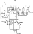
- FIG. 1 is a schematic configuration diagram illustrating a water supply system for aircraft in the present embodiment.
- a water supply system 1 for aircraft is a system that is mounted on an aircraft to supply water to plural water supply outlets 2 in the aircraft.
- the water supply system 1 for aircraft includes a tank 3 for storing water, and a water supply pipe 4 that extends from the tank 3, branches and is connected to each of the plural water supply outlets 2 and supplies water from the tank 3 to the plural water supply outlets 2.
- the tank 3 is a large-size water storage tank storing water, and is also called a water tank or a portable water tank.
- a refilling pipe 5 for supplying water from the outside of the aircraft to the tank 3 is connected to the tank 3.
- a drainage pipe 6 is also connected in such a manner that it branches off the water supply pipe 4 extending out of the tank 3.
- a drain valve 6a which is opened at the time of drainage is provided on the drainage pipe 6.
- the water supply pipe 4 is connected to the tank 3 and the other end branches and is connected to each of the water supply outlets 2.
- the water supply outlets 2 have a water heater 201, a coffee maker 202 and a faucet 203 in a cooking cabinet (galley) 20 and a sink 211 and a toilet bowl cleaning tank 212 in a toilet 21.
- the water supply outlet 2 is not limited to that shown in the drawing and can be appropriately changed.
- a compressed air introduction line 7 for introducing compressed air into the tank 3 is also connected to the tank 3.
- the compressed air introduction line 7 has a first line 71 for introducing compressed air from an engine or auxiliary engine of the aircraft, and a second line 72 for guiding outside air, which is compressed by an air pump 72b, into the tank 3.
- An air filter 71a, a pressure regulator 71b and a check valve 71c are provided on the first line 71.
- An air filter 72a, the air pump 72b and a check valve 72c are provided on the second line 72. Pressure in the tank 3 is increased by compressed air introduced from the compressed air introduction line 7 and water in the tank 3 is thereby supplied to each water supply outlet 2.
- the water supply system 1 for aircraft in the present embodiment includes ultraviolet sterilization devices 8 provided on the water supply pipe 4 respectively close to at least the water supply outlets 2 for drinking water.
- the ultraviolet sterilization device 8 has light-emitting diodes 81 emitting ultraviolet light (see FIG. 2 ), and sterilizes water supplied to the water supply outlets by irradiating the water with ultraviolet light from the light-emitting diodes 81. Sterilization here also includes suppression of bacterial growth by inactivating bacteria.
- the ultraviolet sterilization devices 8 are provided at portions of the water supply pipe 4 respectively connected to the water heater 201, the coffee maker 202 and the faucet 203 in the cooking cabinet 20. In this regard, however, when the branching points of the water supply pipe 4 are close to the water supply outlets 2, one ultraviolet sterilization device 8 may be provided for plural water supply outlets 2.
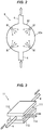
- the ultraviolet sterilization device 8 has a spherical chamber 82 as a sterilization flow path inserted to the water supply pipe 4 and sterilizes water by irradiating water in the chamber 82 with ultraviolet light from the light-emitting diode 81.
- An inner peripheral surface 82a of the chamber 82 is preferably made of a material that reflects ultraviolet light, and it is desirable to improve efficiency of water sterilization by causing multiple reflection of ultraviolet light in the chamber 82. To avoid re-contamination by bacteria, etc., after sterilization, it is desirable to arrange the ultraviolet sterilization devices 8 as close to the water supply outlets 2 as possible.
- the specific configuration of the ultraviolet sterilization device 8 is not limited to the configuration shown in FIG. 2 .
- the light-emitting diode 81 used for the ultraviolet sterilization device 8 preferably emits ultraviolet light with a wavelength of not less than 250 nm and not more than 350 nm. That is, it is desirable to use the light-emitting diode 81 of which center wavelength or peak wavelength is included in the range of not less than 250 nm and not more than 350 nm. To further improve the sterilization effect, it is more desirable to use the light-emitting diode 81 that emits ultraviolet light with a wavelength of not less than 255 nm and not more than 285 nm which has a high bactericidal effect.
- a device for performing sterilization by irradiating water in the tank 3 with ultraviolet light could be provided in the tank 3, but in this case, contamination by bacteria in the water supply pipe 4 is not avoided.
- the ultraviolet sterilization devices 8 on the water supply pipe 4 close to the water supply outlets 2 as in the present embodiment it is possible to kill (or inactivate) bacteria contaminating the tank 3 or the water supply pipe 4 and thereby possible to improve the quality of water supplied through the water supply outlets 2.
- a small running water power generator 9 which generates power using water flowing through the water supply pipe 4 is provided close to each ultraviolet sterilization device 8.
- Each ultraviolet sterilization device 8 is driven using power generated by the corresponding running water power generator 9.
- the ultraviolet sterilization device 8 may alternatively be driven using power generated by the running water power generator 9 and another power. As a result, it is possible to suppress power consumption of the ultraviolet sterilization device 8 and the running cost is reduced.
- a filter 10 for filtering water is provided on the downstream side of each ultraviolet sterilization device 8.
- the filter 10 is provided on the upstream side of the ultraviolet sterilization device 8, the bacteria collected by the filter 10 could grow in the filter 10, causing a decrease in the quality of water.
- the filter 10 is provided on the downstream side of each ultraviolet sterilization device 8 in the present embodiment, it is possible to suppress growth of bacteria in the filter 10.
- a water supply faucet 211a, a sterilized water supply outlet 211b for supplying ozone water and a hand dryer 211c are provided at the sink 211 in the toilet 21.
- the faucet 211a and the sterilized water supply outlet 211b are respectively connected to branches of the water supply pipe 4.
- An ozone water generator 11 for generating and supplying ozone water to the sterilized water supply outlet 211b is provided on the water supply pipe 4 close to the sterilized water supply outlet 211b.
- the ozone water generator 11 has a rectangular parallelepiped-shaped chamber 111 inserted to the water supply pipe 4, and plate-shaped anode and cathode electrodes 112 and 113 provided so as to sandwich the chamber 111.
- the water in the chamber 111 is electrolyzed by applying a voltage between the two electrodes 112, 113 and ozone water is thereby generated.
- a cathode water discharge flow path 114 is connected to the chamber 111 to discharge cathode water that is generated in the chamber 111 and contains a large amount of hydrogen.
- the specific configuration of the ozone water generator 11 is not limited to the configuration shown in FIG. 3 .
- An ozone concentration meter 13 for measuring an ozone concentration in the ozone water generated by the ozone water generator 11 is provided on the downstream side of the ozone water generator 11.
- the ozone concentration meter 13 it is possible to use an ultraviolet light absorbing-type ozone concentration meter that uses a light-emitting diode emitting ultraviolet light.
- a running water power generator that generates power using water flowing through the water supply pipe 4 may be provided to drive the ozone water generator 11 or the ozone concentration meter 13.
- the compressed air introduction line 7 (the first line 71 and the second line 72) is connected to the hand dryer 211c via a dryer connection line 73, and it is configured that compressed air from the compressed air introduction line 7 is blown out of the hand dryer 211c.
- a pressure regulator 73a for regulating pressure of air blown out of the hand dryer 211c is provided on the dryer connection line 73.
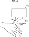
- an ultraviolet light emitter 211d for emitting ultraviolet light onto user's hands to be dried may be provided on the hand dryer 211c, as shown in FIG. 4 .
- a light source used for the ultraviolet light emitter 211d it is desirable to use a light-emitting diode that is low in power consumption.
- ozone water is irradiated with ultraviolet light, hydroxy radicals with a powerful oxidizing action are produced and the sterilization effect is improved by enhanced oxidation. Therefore, it is possible to provide handwashing with higher sterilization effect to passengers by combining the ozone water supply with the hand dryer 211c having the ultraviolet light emitter 211d.
- the ozone water is also used in the toilet bowl cleaning tank 212 used for cleaning the toilet bowl in the toilet.
- the toilet bowl cleaning tank 212 is used to store water for flushing a toilet bowl 213.
- an ozone water generator 12 for generating and supplying ozone water to the toilet bowl cleaning tank 212 is provided on the water supply pipe 4 close to the toilet bowl cleaning tank 212.
- an ozone water generator may be provided in the toilet bowl cleaning tank 212.
- the detailed description of the ozone water generator 12 will be omitted since it has the same structure as the ozone water generator 11 described in reference to FIG. 3 .
- the separate ozone water generators 11 and 12 are used for supplying ozone water to the sterilized water supply outlet 211b and for supplying ozone water to the toilet bowl cleaning tank 212 in the present embodiment, it may be configured such that ozone water generated by one ozone water generator 11 or 12 is supplied to both the sterilized water supply outlet 211b and the toilet bowl cleaning tank 212.
- the toilet bowl 213 By configuring to clean the toilet bowl 213 with ozone water stored in the toilet bowl cleaning tank 212, the toilet bowl 213 can be sterilized every time water is flushed, and it is thus possible to suppress occurrence of airborne bacteria from the toilet bowl 213.
- the water supply system 1 for aircraft in the present embodiment includes the ultraviolet sterilization devices 8 provided on the water supply pipe 4 close to at least the water supply outlets 2 for drinking water, each having light-emitting diodes emitting ultraviolet light, and sterilizing water supplied to the water supply outlets 2 by irradiating the water with ultraviolet light from the light-emitting diodes.
- the ultraviolet sterilization devices 8 By using the ultraviolet sterilization devices 8, it is possible to kill (or inactivate) bacteria contaminating water supplied through the water supply outlets 2 and it is thereby possible to improve the quality of water supplied in the aircraft.
- the ultraviolet sterilization device 8 using the light-emitting diodes is smaller in size and consumes less power than, e.g., a sterilization device using an ultraviolet lamp, etc. Therefore, even in an aircraft having a limited arrangement space, the ultraviolet sterilization device 8 can be easily installed and can be used without power source when, e.g., combined with the running water power generator 9.
Landscapes
- Health & Medical Sciences (AREA)
- Life Sciences & Earth Sciences (AREA)
- Engineering & Computer Science (AREA)
- Public Health (AREA)
- Hydrology & Water Resources (AREA)
- Water Supply & Treatment (AREA)
- Chemical & Material Sciences (AREA)
- Epidemiology (AREA)
- Animal Behavior & Ethology (AREA)
- General Health & Medical Sciences (AREA)
- Veterinary Medicine (AREA)
- Organic Chemistry (AREA)
- Environmental & Geological Engineering (AREA)
- Aviation & Aerospace Engineering (AREA)
- Chemical Kinetics & Catalysis (AREA)
- General Chemical & Material Sciences (AREA)
- Physical Water Treatments (AREA)
- Treatment Of Water By Oxidation Or Reduction (AREA)
- Apparatus For Disinfection Or Sterilisation (AREA)
- Bidet-Like Cleaning Device And Other Flush Toilet Accessories (AREA)
- Domestic Plumbing Installations (AREA)
Abstract
Description
- The invention relates to a water supply system for aircraft.
- In aircrafts, water stored in a dedicated tank is used as drinking water, etc. Pressure in the tank is increased by introducing compressed air taken from an aircraft engine, etc., or compressed air from an air pump, into the tank and water in the tank is thereby sent to predetermined supply outlets (faucets, etc.).
-
Patent Document 1 can be found as prior art document information related to the invention of the present application. - Patent Document 1:
Japanese Translation of PCT International Application Publication No. 2008-528275 - In aircraft water supply systems, tanks and water supply pipes are cleaned with chemicals, etc., to suppress growth of bacteria, etc., in the tanks and water supply pipes. However, sterilization performed by cleaning is not sufficient and very low-quality water is used as drinking water under the current circumstances.
- Particularly with aircrafts, water in the tank is sometimes used as it is in the return flight without being replaced because the water in the tank cannot be discharged in a cold district, etc., and the quality of water stored for a long time is never high.
- An aircraft water supply system having a filter in a water supply pipe has been proposed. However, bacteria collected by the filter could grow in the filter, hence, improvement is desired.
- Therefore, it is an object of the invention to provide a water supply system for aircraft that is capable of improving the quality of water supplied in an aircraft.
- To solve the above-described problem, the invention provides a water supply system for aircraft that is mounted on an aircraft to supply water to a plurality of water supply outlets in the aircraft, the water supply system for aircraft comprising: a tank for storing water; a water supply pipe extending from the tank, branching and being connected to each of the plurality of water supply outlets, and supplying water from the tank to the plurality of water supply outlets; and an ultraviolet sterilization device provided on the water supply pipe close to at least the water supply outlet for drinking water, comprising a light-emitting diode emitting ultraviolet light, and sterilizing water supplied to the water supply outlet by irradiating the water with ultraviolet light from the light-emitting diode.
- According to the invention, it is possible to provide a water supply system for aircraft that is capable of improving the quality of water supplied in an aircraft.
-
-
FIG. 1 is a schematic configuration diagram illustrating a water supply system for aircraft in an embodiment of the present invention. -
FIG. 2 is a schematic configuration diagram illustrating an example of an ultraviolet sterilization device. -
FIG. 3 is a schematic configuration diagram illustrating an example of an ozone water generator. -
FIG. 4 is a schematic configuration diagram illustrating a hand dryer. - An embodiment of the invention will be described below in conjunction with the appended drawings.
-
FIG. 1 is a schematic configuration diagram illustrating a water supply system for aircraft in the present embodiment. As shown inFIG. 1 , awater supply system 1 for aircraft is a system that is mounted on an aircraft to supply water to pluralwater supply outlets 2 in the aircraft. - The
water supply system 1 for aircraft includes atank 3 for storing water, and awater supply pipe 4 that extends from thetank 3, branches and is connected to each of the pluralwater supply outlets 2 and supplies water from thetank 3 to the pluralwater supply outlets 2. - The
tank 3 is a large-size water storage tank storing water, and is also called a water tank or a portable water tank. Arefilling pipe 5 for supplying water from the outside of the aircraft to thetank 3 is connected to thetank 3. Adrainage pipe 6 is also connected in such a manner that it branches off thewater supply pipe 4 extending out of thetank 3. Adrain valve 6a which is opened at the time of drainage is provided on thedrainage pipe 6. - One end of the
water supply pipe 4 is connected to thetank 3 and the other end branches and is connected to each of thewater supply outlets 2. In the example described here, thewater supply outlets 2 have awater heater 201, acoffee maker 202 and afaucet 203 in a cooking cabinet (galley) 20 and asink 211 and a toiletbowl cleaning tank 212 in atoilet 21. However, thewater supply outlet 2 is not limited to that shown in the drawing and can be appropriately changed. - A compressed air introduction line 7 for introducing compressed air into the
tank 3 is also connected to thetank 3. The compressed air introduction line 7 has afirst line 71 for introducing compressed air from an engine or auxiliary engine of the aircraft, and a second line 72 for guiding outside air, which is compressed by an air pump 72b, into thetank 3. Anair filter 71a, apressure regulator 71b and acheck valve 71c are provided on thefirst line 71. An air filter 72a, the air pump 72b and a check valve 72c are provided on the second line 72. Pressure in thetank 3 is increased by compressed air introduced from the compressed air introduction line 7 and water in thetank 3 is thereby supplied to eachwater supply outlet 2. - The
water supply system 1 for aircraft in the present embodiment includesultraviolet sterilization devices 8 provided on thewater supply pipe 4 respectively close to at least thewater supply outlets 2 for drinking water. Theultraviolet sterilization device 8 has light-emitting diodes 81 emitting ultraviolet light (seeFIG. 2 ), and sterilizes water supplied to the water supply outlets by irradiating the water with ultraviolet light from the light-emitting diodes 81. Sterilization here also includes suppression of bacterial growth by inactivating bacteria. - In the present embodiment, the
ultraviolet sterilization devices 8 are provided at portions of thewater supply pipe 4 respectively connected to thewater heater 201, thecoffee maker 202 and thefaucet 203 in thecooking cabinet 20. In this regard, however, when the branching points of thewater supply pipe 4 are close to thewater supply outlets 2, oneultraviolet sterilization device 8 may be provided for pluralwater supply outlets 2. - As shown in
FIG. 2 , theultraviolet sterilization device 8 has aspherical chamber 82 as a sterilization flow path inserted to thewater supply pipe 4 and sterilizes water by irradiating water in thechamber 82 with ultraviolet light from the light-emitting diode 81. An innerperipheral surface 82a of thechamber 82 is preferably made of a material that reflects ultraviolet light, and it is desirable to improve efficiency of water sterilization by causing multiple reflection of ultraviolet light in thechamber 82. To avoid re-contamination by bacteria, etc., after sterilization, it is desirable to arrange theultraviolet sterilization devices 8 as close to thewater supply outlets 2 as possible. The specific configuration of theultraviolet sterilization device 8 is not limited to the configuration shown inFIG. 2 . - The light-
emitting diode 81 used for theultraviolet sterilization device 8 preferably emits ultraviolet light with a wavelength of not less than 250 nm and not more than 350 nm. That is, it is desirable to use the light-emittingdiode 81 of which center wavelength or peak wavelength is included in the range of not less than 250 nm and not more than 350 nm. To further improve the sterilization effect, it is more desirable to use the light-emitting diode 81 that emits ultraviolet light with a wavelength of not less than 255 nm and not more than 285 nm which has a high bactericidal effect. - In this regard, for example, a device for performing sterilization by irradiating water in the
tank 3 with ultraviolet light could be provided in thetank 3, but in this case, contamination by bacteria in thewater supply pipe 4 is not avoided. By providing theultraviolet sterilization devices 8 on thewater supply pipe 4 close to thewater supply outlets 2 as in the present embodiment, it is possible to kill (or inactivate) bacteria contaminating thetank 3 or thewater supply pipe 4 and thereby possible to improve the quality of water supplied through thewater supply outlets 2. - Returning back to
FIG. 1 , in the present embodiment, a small runningwater power generator 9 which generates power using water flowing through thewater supply pipe 4 is provided close to eachultraviolet sterilization device 8. Eachultraviolet sterilization device 8 is driven using power generated by the corresponding runningwater power generator 9. Theultraviolet sterilization device 8 may alternatively be driven using power generated by the runningwater power generator 9 and another power. As a result, it is possible to suppress power consumption of theultraviolet sterilization device 8 and the running cost is reduced. - In addition, in the present embodiment, a
filter 10 for filtering water is provided on the downstream side of eachultraviolet sterilization device 8. For example, if thefilter 10 is provided on the upstream side of theultraviolet sterilization device 8, the bacteria collected by thefilter 10 could grow in thefilter 10, causing a decrease in the quality of water. In contrast, since thefilter 10 is provided on the downstream side of eachultraviolet sterilization device 8 in the present embodiment, it is possible to suppress growth of bacteria in thefilter 10. - In the
water supply system 1 for aircraft in the present embodiment, awater supply faucet 211a, a sterilizedwater supply outlet 211b for supplying ozone water and ahand dryer 211c are provided at thesink 211 in thetoilet 21. Thefaucet 211a and the sterilizedwater supply outlet 211b are respectively connected to branches of thewater supply pipe 4. - An
ozone water generator 11 for generating and supplying ozone water to the sterilizedwater supply outlet 211b is provided on thewater supply pipe 4 close to the sterilizedwater supply outlet 211b. As shown inFIG. 3 , theozone water generator 11 has a rectangular parallelepiped-shapedchamber 111 inserted to thewater supply pipe 4, and plate-shaped anode andcathode electrodes chamber 111. The water in thechamber 111 is electrolyzed by applying a voltage between the twoelectrodes discharge flow path 114 is connected to thechamber 111 to discharge cathode water that is generated in thechamber 111 and contains a large amount of hydrogen. The specific configuration of theozone water generator 11 is not limited to the configuration shown inFIG. 3 . - An
ozone concentration meter 13 for measuring an ozone concentration in the ozone water generated by theozone water generator 11 is provided on the downstream side of theozone water generator 11. As theozone concentration meter 13, it is possible to use an ultraviolet light absorbing-type ozone concentration meter that uses a light-emitting diode emitting ultraviolet light. A running water power generator that generates power using water flowing through thewater supply pipe 4 may be provided to drive theozone water generator 11 or theozone concentration meter 13. - In aircrafts, part of drainage water is discharged from a drain mast to the outside, but wastewater from toilets, etc., is stored in a waste tank. Drainage water from the
sink 211 is also stored in the waste tank. However, when soap is used in thesink 211, the waste tank becomes sudsy and it makes post-treatment awkward. For this reason, less lathering soap is generally used in thesink 211 under the current circumstances, but it is difficult to obtain a sufficient sterilization effect only by such a measure. By enabling handwashing with ozone water at thesink 211 as in the present embodiment, it is possible to obtain a sufficient sterilization effect. In addition, since the ozone water is collected into the waste tank, it is also possible to sterilize the waste tank. - The compressed air introduction line 7 (the
first line 71 and the second line 72) is connected to thehand dryer 211c via adryer connection line 73, and it is configured that compressed air from the compressed air introduction line 7 is blown out of thehand dryer 211c. Apressure regulator 73a for regulating pressure of air blown out of thehand dryer 211c is provided on thedryer connection line 73. By configuring so that thehand dryer 211c uses compressed air from the compressed air introduction line 7, the necessity of driving a fan as in the conventional technique is eliminated and it is possible to reduce power consumption. - Additionally, an
ultraviolet light emitter 211d for emitting ultraviolet light onto user's hands to be dried may be provided on thehand dryer 211c, as shown inFIG. 4 . As a light source used for theultraviolet light emitter 211d, it is desirable to use a light-emitting diode that is low in power consumption. When ozone water is irradiated with ultraviolet light, hydroxy radicals with a powerful oxidizing action are produced and the sterilization effect is improved by enhanced oxidation. Therefore, it is possible to provide handwashing with higher sterilization effect to passengers by combining the ozone water supply with thehand dryer 211c having theultraviolet light emitter 211d. - Furthermore, in the present embodiment, it is configured that the ozone water is also used in the toilet
bowl cleaning tank 212 used for cleaning the toilet bowl in the toilet. In this regard, the toiletbowl cleaning tank 212 is used to store water for flushing atoilet bowl 213. - In the present embodiment, an
ozone water generator 12 for generating and supplying ozone water to the toiletbowl cleaning tank 212 is provided on thewater supply pipe 4 close to the toiletbowl cleaning tank 212. However, it is not limited thereto, and an ozone water generator may be provided in the toiletbowl cleaning tank 212. The detailed description of theozone water generator 12 will be omitted since it has the same structure as theozone water generator 11 described in reference toFIG. 3 . Although the separateozone water generators water supply outlet 211b and for supplying ozone water to the toiletbowl cleaning tank 212 in the present embodiment, it may be configured such that ozone water generated by oneozone water generator water supply outlet 211b and the toiletbowl cleaning tank 212. - By configuring to clean the
toilet bowl 213 with ozone water stored in the toiletbowl cleaning tank 212, thetoilet bowl 213 can be sterilized every time water is flushed, and it is thus possible to suppress occurrence of airborne bacteria from thetoilet bowl 213. - As described above, the
water supply system 1 for aircraft in the present embodiment includes theultraviolet sterilization devices 8 provided on thewater supply pipe 4 close to at least thewater supply outlets 2 for drinking water, each having light-emitting diodes emitting ultraviolet light, and sterilizing water supplied to thewater supply outlets 2 by irradiating the water with ultraviolet light from the light-emitting diodes. - By using the
ultraviolet sterilization devices 8, it is possible to kill (or inactivate) bacteria contaminating water supplied through thewater supply outlets 2 and it is thereby possible to improve the quality of water supplied in the aircraft. Theultraviolet sterilization device 8 using the light-emitting diodes is smaller in size and consumes less power than, e.g., a sterilization device using an ultraviolet lamp, etc. Therefore, even in an aircraft having a limited arrangement space, theultraviolet sterilization device 8 can be easily installed and can be used without power source when, e.g., combined with the runningwater power generator 9. - Technical ideas understood from the embodiment will be described below citing the reference numerals, etc., used for the embodiment. However, each reference numeral, etc., described below is not intended to limit the constituent elements in the claims to the members, etc., specifically described in the embodiment.
- [1] A water supply system (1) for aircraft that is mounted on an aircraft to supply water to a plurality of water supply outlets (2) in the aircraft, the water supply system (1) for aircraft comprising: a tank (3) for storing water; a water supply pipe (4) extending from the tank (3), branching and being connected to each of the plurality of water supply outlets (2), and supplying water from the tank (3) to the plurality of water supply outlets (2); and an ultraviolet sterilization device (8) provided on the water supply pipe (4) close to at least the water supply outlet (2) for drinking water, comprising a light-emitting diode emitting ultraviolet light, and sterilizing water supplied to the water supply outlet (2) by irradiating the water with ultraviolet light from the light-emitting diode.
- [2] The water supply system (1) for aircraft described in [1], comprising: a running water power generator (9) that generates power using water flowing through the water supply pipe (4), wherein the ultraviolet sterilization device (8) is driven using power generated by the running water power generator (9).
- [3] The water supply system (1) for aircraft described in [1] or [2], wherein a filter (10) for filtering the water is provided on the downstream side of the ultraviolet sterilization device (8).
- [4] The water supply system (1) for aircraft described in any one of [1] to [3], wherein the water supply outlets (2) comprise a sterilized water supply outlet (211b) provided at a sink (21a), and an ozone water generator (11) for generating and supplying ozone water to the sterilized water supply outlet (211b) is provided on the water supply pipe (4) close to the sterilized water supply outlet (211b).
- [5] The water supply system (1) for aircraft described in any one of [1] to [4], wherein the water supply outlets (2) comprise a toilet bowl cleaning tank (21b) used for cleaning a toilet bowl in a toilet (21), and an ozone water generator (12) for generating and supplying ozone water to the toilet bowl cleaning tank (21b) is provided on the water supply pipe (4) close to the toilet bowl cleaning tank (21b), or provided in the toilet bowl cleaning tank (21b).
- Although the embodiment of the invention has been described, the invention according to claims is not to be limited to the embodiment described above. In addition, all combinations of the features described in the embodiment are not necessary to solve the problem of the invention. In addition, the invention can be appropriately modified and implemented without departing from the gist thereof.
-
- 1:
- water supply system for aircraft
- 2:
- water supply outlet
- 3:
- tank
- 4:
- water supply pipe
- 8:
- ultraviolet sterilization device
- 9:
- running water power generator
- 10:
- filter
- 11, 12:
- ozone water generator
- 21:
- toilet
- 211:
- sink
- 211b:
- sterilized water supply outlet
- 211c:
- hand dryer
- 212:
- toilet bowl cleaning tank
- 213:
- toilet bowl
Claims (5)
- A water supply system for aircraft that is mounted on an aircraft to supply water to a plurality of water supply outlets in the aircraft, the water supply system for aircraft comprising:a tank for storing water;a water supply pipe extending from the tank, branching and being connected to each of the plurality of water supply outlets, and supplying water from the tank to the plurality of water supply outlets; andan ultraviolet sterilization device provided on the water supply pipe close to at least the water supply outlet for drinking water, comprising a light-emitting diode emitting ultraviolet light, and sterilizing water supplied to the water supply outlet by irradiating the water with ultraviolet light from the light-emitting diode.
- The water supply system for aircraft according to claim 1, comprising:a running water power generator that generates power using water flowing through the water supply pipe,wherein the ultraviolet sterilization device is driven using power generated by the running water power generator.
- The water supply system for aircraft according to claim 1 or 2, wherein a filter for filtering the water is provided on the downstream side of the ultraviolet sterilization device.
- The water supply system for aircraft according to any one of claims 1 to 3, wherein the water supply outlets comprise a sterilized water supply outlet provided at a sink, and an ozone water generator for generating and supplying ozone water to the sterilized water supply outlet is provided on the water supply pipe close to the sterilized water supply outlet.
- The water supply system for aircraft according to any one of claims 1 to 4, wherein the water supply outlets comprise a toilet bowl cleaning tank used for cleaning a toilet bowl in a toilet, and an ozone water generator for generating and supplying ozone water to the toilet bowl cleaning tank is provided on the water supply pipe close to the toilet bowl cleaning tank, or provided in the toilet bowl cleaning tank.
Applications Claiming Priority (2)
| Application Number | Priority Date | Filing Date | Title |
|---|---|---|---|
| JP2018235300A JP7202872B2 (en) | 2018-12-17 | 2018-12-17 | Aircraft water supply system |
| PCT/JP2019/047884 WO2020129711A1 (en) | 2018-12-17 | 2019-12-06 | Water supply system for aircraft |
Publications (3)
| Publication Number | Publication Date |
|---|---|
| EP3901037A1 true EP3901037A1 (en) | 2021-10-27 |
| EP3901037A4 EP3901037A4 (en) | 2022-09-14 |
| EP3901037B1 EP3901037B1 (en) | 2025-07-02 |
Family
ID=71102776
Family Applications (1)
| Application Number | Title | Priority Date | Filing Date |
|---|---|---|---|
| EP19899893.2A Active EP3901037B1 (en) | 2018-12-17 | 2019-12-06 | Water supply system for aircraft |
Country Status (5)
| Country | Link |
|---|---|
| US (1) | US12330974B2 (en) |
| EP (1) | EP3901037B1 (en) |
| JP (1) | JP7202872B2 (en) |
| CN (1) | CN113195359B (en) |
| WO (1) | WO2020129711A1 (en) |
Families Citing this family (5)
| Publication number | Priority date | Publication date | Assignee | Title |
|---|---|---|---|---|
| EP4282759B1 (en) * | 2022-05-25 | 2025-11-26 | Airbus Operations GmbH | Method for draining a local water distribution system |
| EP4282758B1 (en) * | 2022-05-25 | 2025-02-26 | Airbus Operations GmbH | Method for pneumatically draining a water supply system |
| EP4389601A1 (en) * | 2022-12-20 | 2024-06-26 | Airbus Operations GmbH | Water supply and distribution system on-board an aircraft and method for operating such system |
| EP4389602A1 (en) * | 2022-12-20 | 2024-06-26 | Airbus Operations GmbH | Water supply and distribution system on-board an aircraft and method for operating such system |
| EP4635848A1 (en) * | 2024-04-16 | 2025-10-22 | AIRBUS Operations GmbH | Water supply and distribution system with optimized utilization of onboard water |
Family Cites Families (29)
| Publication number | Priority date | Publication date | Assignee | Title |
|---|---|---|---|---|
| DE3715759A1 (en) * | 1987-05-12 | 1988-12-01 | Messerschmitt Boelkow Blohm | WATER SUPPLY ARRANGEMENT, IN PARTICULAR ON BOARD A PLANE |
| DE10259997B4 (en) * | 2002-12-20 | 2007-09-13 | Airbus Deutschland Gmbh | Aircraft toilet system |
| US7396459B2 (en) * | 2003-05-05 | 2008-07-08 | George W Thorpe | Internal UV treatment of potable water systems |
| JP4809233B2 (en) * | 2003-05-13 | 2011-11-09 | イー・アイ・デュポン・ドウ・ヌムール・アンド・カンパニー | Reinforced polyoxymethylene-polylactic acid composition |
| JP2005002570A (en) * | 2003-06-09 | 2005-01-06 | Denso Corp | Faucet device with lighting function |
| US7675188B2 (en) * | 2003-10-09 | 2010-03-09 | Access Business Group International, Llc | Miniature hydro-power generation system |
| DE10349158A1 (en) * | 2003-10-22 | 2005-06-16 | Airbus Deutschland Gmbh | Device for water supply in aircraft |
| US7211187B2 (en) * | 2004-10-29 | 2007-05-01 | Steven Lumbert | Mobile or stationary modular self-contained dehydration toilet, dehydration engine, and gray water recovery system |
| US20060157425A1 (en) * | 2005-01-19 | 2006-07-20 | Heavy Industry Technology Solutions, Llc | Methods and systems for treating wastewater using ultraviolet light |
| US20060169645A1 (en) | 2005-01-31 | 2006-08-03 | Hsueh Angela M | Water treatment systems and techniques principally for use on-board aircraft |
| US7666317B2 (en) | 2005-01-31 | 2010-02-23 | MAC Aerospace Industries, Inc. | Methods and systems for disinfecting potable water supplies |
| JP2007031983A (en) * | 2005-07-25 | 2007-02-08 | Inax Corp | Water discharge device |
| DE102008036425B4 (en) | 2008-08-05 | 2010-09-23 | Airbus Deutschland Gmbh | System for targeted local humidification |
| GB0821427D0 (en) * | 2008-11-24 | 2008-12-31 | Qinetiq Ltd | Waste management |
| CA2686836C (en) | 2008-12-01 | 2017-04-11 | International Water-Guard Industries, Inc. | Water distribution system with dual use water treatment unit |
| US20100314551A1 (en) * | 2009-06-11 | 2010-12-16 | Bettles Timothy J | In-line Fluid Treatment by UV Radiation |
| US8872130B1 (en) * | 2012-03-19 | 2014-10-28 | Meridian Design, Inc. | UVC water purifier system and method |
| DE102011110105A1 (en) * | 2011-08-12 | 2013-02-14 | Airbus Operations Gmbh | Water supply system with bi-directional UV disinfection device |
| CA2856196C (en) * | 2011-12-06 | 2020-09-01 | Masco Corporation Of Indiana | Ozone distribution in a faucet |
| WO2013086274A1 (en) * | 2011-12-09 | 2013-06-13 | Mag Aerospace Industries, Inc. | Inline uv led water disinfection and heating |
| US9296480B2 (en) * | 2012-03-19 | 2016-03-29 | Mag Aerospace Industries, Llc | Use of at least one output of a fuel cell system in a lavatory |
| US20140017135A1 (en) * | 2012-07-16 | 2014-01-16 | Mag Aerospace Industries, Inc. | Systems and Methods for Disinfecting Air On Board A Passenger Transport Vehicle |
| DE102013103517A1 (en) | 2013-04-09 | 2014-10-09 | Candilux GmbH | Device for water treatment by means of UV light |
| WO2015069680A1 (en) * | 2013-11-08 | 2015-05-14 | Mag Aerospace Industries, Llc | Point of use water treatment device |
| US20160311699A1 (en) * | 2015-04-21 | 2016-10-27 | Chris Burseth | Device and system to improve asepsis in dental apparatus |
| CN108025182B (en) * | 2015-07-14 | 2021-08-13 | 维塔比姆有限公司 | Methods and devices for disinfection, sterilization and sterilization |
| JP2017180014A (en) * | 2016-03-31 | 2017-10-05 | アイシン精機株式会社 | Sanitary washing apparatus |
| US10662627B2 (en) * | 2016-08-16 | 2020-05-26 | The Boeing Company | Ultraviolet light treating water dispensation systems and methods |
| EP4365081B1 (en) * | 2017-04-07 | 2026-05-06 | Airbus Operations GmbH | An aircraft comprising a high-pressure water supply and distribution system |
-
2018
- 2018-12-17 JP JP2018235300A patent/JP7202872B2/en active Active
-
2019
- 2019-12-06 EP EP19899893.2A patent/EP3901037B1/en active Active
- 2019-12-06 US US17/414,710 patent/US12330974B2/en active Active
- 2019-12-06 WO PCT/JP2019/047884 patent/WO2020129711A1/en not_active Ceased
- 2019-12-06 CN CN201980083694.0A patent/CN113195359B/en active Active
Also Published As
| Publication number | Publication date |
|---|---|
| JP7202872B2 (en) | 2023-01-12 |
| US12330974B2 (en) | 2025-06-17 |
| EP3901037B1 (en) | 2025-07-02 |
| US20220064039A1 (en) | 2022-03-03 |
| CN113195359B (en) | 2023-12-29 |
| EP3901037A4 (en) | 2022-09-14 |
| CN113195359A (en) | 2021-07-30 |
| WO2020129711A1 (en) | 2020-06-25 |
| JP2020097265A (en) | 2020-06-25 |
Similar Documents
| Publication | Publication Date | Title |
|---|---|---|
| US12330974B2 (en) | Water supply system for aircraft | |
| DK2323952T3 (en) | A disinfection device with the power supply means and the liquid outlet | |
| US7055183B2 (en) | Method and apparatus for cleaning and disinfecting a toilet system in a transport vehicle such as a passenger aircraft | |
| KR101776029B1 (en) | Apparatus for sterilizing toilet water and the method thereof | |
| US10266426B1 (en) | UV water treatment in portable water tank | |
| US8043500B2 (en) | Aircraft potable water disinfection/sanitation system | |
| WO2016157992A1 (en) | Sanitary washing device | |
| JP2020097265A5 (en) | ||
| TW202128069A (en) | Sanitary washing device | |
| TW202003974A (en) | Sanitary washing device | |
| CN206128240U (en) | Sanitary washing device | |
| KR102213489B1 (en) | Sanitary washing device | |
| JP2009226323A (en) | Ozone water generator | |
| US11142471B2 (en) | Water system floor interface with ultraviolet light treatment | |
| US20150188171A1 (en) | Microbiologically protected fuel cell | |
| WO2023032589A1 (en) | Electrolytic liquid generation system and control system | |
| CN210020471U (en) | Disinfection vehicle | |
| JP2018009301A (en) | Sanitary washing device | |
| JP2007014888A (en) | Disinfection equipment | |
| JP2017127378A (en) | Washstand | |
| JP2019183594A (en) | High efficiency waste disposal apparatus | |
| JP6668924B2 (en) | Sanitary washing equipment | |
| JP2017127391A (en) | Bathroom vanity | |
| JP2017197993A (en) | Sanitary washing device | |
| WO2025098772A1 (en) | Hand washing station |
Legal Events
| Date | Code | Title | Description |
|---|---|---|---|
| STAA | Information on the status of an ep patent application or granted ep patent |
Free format text: STATUS: THE INTERNATIONAL PUBLICATION HAS BEEN MADE |
|
| PUAI | Public reference made under article 153(3) epc to a published international application that has entered the european phase |
Free format text: ORIGINAL CODE: 0009012 |
|
| STAA | Information on the status of an ep patent application or granted ep patent |
Free format text: STATUS: REQUEST FOR EXAMINATION WAS MADE |
|
| 17P | Request for examination filed |
Effective date: 20210610 |
|
| AK | Designated contracting states |
Kind code of ref document: A1 Designated state(s): AL AT BE BG CH CY CZ DE DK EE ES FI FR GB GR HR HU IE IS IT LI LT LU LV MC MK MT NL NO PL PT RO RS SE SI SK SM TR |
|
| DAV | Request for validation of the european patent (deleted) | ||
| DAX | Request for extension of the european patent (deleted) | ||
| A4 | Supplementary search report drawn up and despatched |
Effective date: 20220817 |
|
| RIC1 | Information provided on ipc code assigned before grant |
Ipc: C02F 9/00 20060101ALI20220810BHEP Ipc: C02F 1/00 20060101ALI20220810BHEP Ipc: A61L 101/10 20060101ALI20220810BHEP Ipc: E03D 9/02 20060101ALI20220810BHEP Ipc: E03D 9/00 20060101ALI20220810BHEP Ipc: E03C 1/10 20060101ALI20220810BHEP Ipc: E03C 1/02 20060101ALI20220810BHEP Ipc: C02F 1/78 20060101ALI20220810BHEP Ipc: C02F 1/50 20060101ALI20220810BHEP Ipc: C02F 1/32 20060101ALI20220810BHEP Ipc: A61L 2/18 20060101ALI20220810BHEP Ipc: B64D 11/02 20060101AFI20220810BHEP |
|
| P01 | Opt-out of the competence of the unified patent court (upc) registered |
Effective date: 20230512 |
|
| STAA | Information on the status of an ep patent application or granted ep patent |
Free format text: STATUS: EXAMINATION IS IN PROGRESS |
|
| 17Q | First examination report despatched |
Effective date: 20240222 |
|
| GRAP | Despatch of communication of intention to grant a patent |
Free format text: ORIGINAL CODE: EPIDOSNIGR1 |
|
| STAA | Information on the status of an ep patent application or granted ep patent |
Free format text: STATUS: GRANT OF PATENT IS INTENDED |
|
| INTG | Intention to grant announced |
Effective date: 20250220 |
|
| GRAS | Grant fee paid |
Free format text: ORIGINAL CODE: EPIDOSNIGR3 |
|
| GRAA | (expected) grant |
Free format text: ORIGINAL CODE: 0009210 |
|
| STAA | Information on the status of an ep patent application or granted ep patent |
Free format text: STATUS: THE PATENT HAS BEEN GRANTED |
|
| AK | Designated contracting states |
Kind code of ref document: B1 Designated state(s): AL AT BE BG CH CY CZ DE DK EE ES FI FR GB GR HR HU IE IS IT LI LT LU LV MC MK MT NL NO PL PT RO RS SE SI SK SM TR |
|
| REG | Reference to a national code |
Ref country code: GB Ref legal event code: FG4D |
|
| REG | Reference to a national code |
Ref country code: CH Ref legal event code: EP |
|
| REG | Reference to a national code |
Ref country code: DE Ref legal event code: R096 Ref document number: 602019072123 Country of ref document: DE |
|
| REG | Reference to a national code |
Ref country code: IE Ref legal event code: FG4D |
|
| REG | Reference to a national code |
Ref country code: NL Ref legal event code: MP Effective date: 20250702 |
|
| PG25 | Lapsed in a contracting state [announced via postgrant information from national office to epo] |
Ref country code: PT Free format text: LAPSE BECAUSE OF FAILURE TO SUBMIT A TRANSLATION OF THE DESCRIPTION OR TO PAY THE FEE WITHIN THE PRESCRIBED TIME-LIMIT Effective date: 20251103 |
|
| PG25 | Lapsed in a contracting state [announced via postgrant information from national office to epo] |
Ref country code: NL Free format text: LAPSE BECAUSE OF FAILURE TO SUBMIT A TRANSLATION OF THE DESCRIPTION OR TO PAY THE FEE WITHIN THE PRESCRIBED TIME-LIMIT Effective date: 20250702 |
|
| REG | Reference to a national code |
Ref country code: AT Ref legal event code: MK05 Ref document number: 1808986 Country of ref document: AT Kind code of ref document: T Effective date: 20250702 |
|
| PG25 | Lapsed in a contracting state [announced via postgrant information from national office to epo] |
Ref country code: IS Free format text: LAPSE BECAUSE OF FAILURE TO SUBMIT A TRANSLATION OF THE DESCRIPTION OR TO PAY THE FEE WITHIN THE PRESCRIBED TIME-LIMIT Effective date: 20251102 |
|
| PG25 | Lapsed in a contracting state [announced via postgrant information from national office to epo] |
Ref country code: NO Free format text: LAPSE BECAUSE OF FAILURE TO SUBMIT A TRANSLATION OF THE DESCRIPTION OR TO PAY THE FEE WITHIN THE PRESCRIBED TIME-LIMIT Effective date: 20251002 |
|
| REG | Reference to a national code |
Ref country code: LT Ref legal event code: MG9D |
|
| PG25 | Lapsed in a contracting state [announced via postgrant information from national office to epo] |
Ref country code: AT Free format text: LAPSE BECAUSE OF FAILURE TO SUBMIT A TRANSLATION OF THE DESCRIPTION OR TO PAY THE FEE WITHIN THE PRESCRIBED TIME-LIMIT Effective date: 20250702 |
|
| PG25 | Lapsed in a contracting state [announced via postgrant information from national office to epo] |
Ref country code: FI Free format text: LAPSE BECAUSE OF FAILURE TO SUBMIT A TRANSLATION OF THE DESCRIPTION OR TO PAY THE FEE WITHIN THE PRESCRIBED TIME-LIMIT Effective date: 20250702 |
|
| PG25 | Lapsed in a contracting state [announced via postgrant information from national office to epo] |
Ref country code: HR Free format text: LAPSE BECAUSE OF FAILURE TO SUBMIT A TRANSLATION OF THE DESCRIPTION OR TO PAY THE FEE WITHIN THE PRESCRIBED TIME-LIMIT Effective date: 20250702 |
|
| PGFP | Annual fee paid to national office [announced via postgrant information from national office to epo] |
Ref country code: FR Payment date: 20251112 Year of fee payment: 7 |
|
| PG25 | Lapsed in a contracting state [announced via postgrant information from national office to epo] |
Ref country code: GR Free format text: LAPSE BECAUSE OF FAILURE TO SUBMIT A TRANSLATION OF THE DESCRIPTION OR TO PAY THE FEE WITHIN THE PRESCRIBED TIME-LIMIT Effective date: 20251003 |
|
| PG25 | Lapsed in a contracting state [announced via postgrant information from national office to epo] |
Ref country code: CZ Free format text: LAPSE BECAUSE OF FAILURE TO SUBMIT A TRANSLATION OF THE DESCRIPTION OR TO PAY THE FEE WITHIN THE PRESCRIBED TIME-LIMIT Effective date: 20250702 Ref country code: SE Free format text: LAPSE BECAUSE OF FAILURE TO SUBMIT A TRANSLATION OF THE DESCRIPTION OR TO PAY THE FEE WITHIN THE PRESCRIBED TIME-LIMIT Effective date: 20250702 |
|
| PG25 | Lapsed in a contracting state [announced via postgrant information from national office to epo] |
Ref country code: LV Free format text: LAPSE BECAUSE OF FAILURE TO SUBMIT A TRANSLATION OF THE DESCRIPTION OR TO PAY THE FEE WITHIN THE PRESCRIBED TIME-LIMIT Effective date: 20250702 |
|
| PG25 | Lapsed in a contracting state [announced via postgrant information from national office to epo] |
Ref country code: PL Free format text: LAPSE BECAUSE OF FAILURE TO SUBMIT A TRANSLATION OF THE DESCRIPTION OR TO PAY THE FEE WITHIN THE PRESCRIBED TIME-LIMIT Effective date: 20250702 Ref country code: BG Free format text: LAPSE BECAUSE OF FAILURE TO SUBMIT A TRANSLATION OF THE DESCRIPTION OR TO PAY THE FEE WITHIN THE PRESCRIBED TIME-LIMIT Effective date: 20250702 |
|
| PG25 | Lapsed in a contracting state [announced via postgrant information from national office to epo] |
Ref country code: RS Free format text: LAPSE BECAUSE OF FAILURE TO SUBMIT A TRANSLATION OF THE DESCRIPTION OR TO PAY THE FEE WITHIN THE PRESCRIBED TIME-LIMIT Effective date: 20251002 |
|
| PG25 | Lapsed in a contracting state [announced via postgrant information from national office to epo] |
Ref country code: ES Free format text: LAPSE BECAUSE OF FAILURE TO SUBMIT A TRANSLATION OF THE DESCRIPTION OR TO PAY THE FEE WITHIN THE PRESCRIBED TIME-LIMIT Effective date: 20250702 |
|
| PG25 | Lapsed in a contracting state [announced via postgrant information from national office to epo] |
Ref country code: RO Free format text: LAPSE BECAUSE OF FAILURE TO SUBMIT A TRANSLATION OF THE DESCRIPTION OR TO PAY THE FEE WITHIN THE PRESCRIBED TIME-LIMIT Effective date: 20250702 |
|
| PG25 | Lapsed in a contracting state [announced via postgrant information from national office to epo] |
Ref country code: SM Free format text: LAPSE BECAUSE OF FAILURE TO SUBMIT A TRANSLATION OF THE DESCRIPTION OR TO PAY THE FEE WITHIN THE PRESCRIBED TIME-LIMIT Effective date: 20250702 |
|
| PG25 | Lapsed in a contracting state [announced via postgrant information from national office to epo] |
Ref country code: DK Free format text: LAPSE BECAUSE OF FAILURE TO SUBMIT A TRANSLATION OF THE DESCRIPTION OR TO PAY THE FEE WITHIN THE PRESCRIBED TIME-LIMIT Effective date: 20250702 |
|
| PGFP | Annual fee paid to national office [announced via postgrant information from national office to epo] |
Ref country code: DE Payment date: 20251217 Year of fee payment: 7 |
|
| PG25 | Lapsed in a contracting state [announced via postgrant information from national office to epo] |
Ref country code: IT Free format text: LAPSE BECAUSE OF FAILURE TO SUBMIT A TRANSLATION OF THE DESCRIPTION OR TO PAY THE FEE WITHIN THE PRESCRIBED TIME-LIMIT Effective date: 20250702 |
|
| PG25 | Lapsed in a contracting state [announced via postgrant information from national office to epo] |
Ref country code: SK Free format text: LAPSE BECAUSE OF FAILURE TO SUBMIT A TRANSLATION OF THE DESCRIPTION OR TO PAY THE FEE WITHIN THE PRESCRIBED TIME-LIMIT Effective date: 20250702 Ref country code: EE Free format text: LAPSE BECAUSE OF FAILURE TO SUBMIT A TRANSLATION OF THE DESCRIPTION OR TO PAY THE FEE WITHIN THE PRESCRIBED TIME-LIMIT Effective date: 20250702 |
|
| PLBE | No opposition filed within time limit |
Free format text: ORIGINAL CODE: 0009261 |
|
| STAA | Information on the status of an ep patent application or granted ep patent |
Free format text: STATUS: NO OPPOSITION FILED WITHIN TIME LIMIT |