EP3901026A1 - Insulation wall fixing device for liquefied natural gas storage tank - Google Patents
Insulation wall fixing device for liquefied natural gas storage tank Download PDFInfo
- Publication number
- EP3901026A1 EP3901026A1 EP19897777.9A EP19897777A EP3901026A1 EP 3901026 A1 EP3901026 A1 EP 3901026A1 EP 19897777 A EP19897777 A EP 19897777A EP 3901026 A1 EP3901026 A1 EP 3901026A1
- Authority
- EP
- European Patent Office
- Prior art keywords
- insulation wall
- fixing device
- storage tank
- socket
- base socket
- Prior art date
- Legal status (The legal status is an assumption and is not a legal conclusion. Google has not performed a legal analysis and makes no representation as to the accuracy of the status listed.)
- Granted
Links
Images


Classifications
-
- F—MECHANICAL ENGINEERING; LIGHTING; HEATING; WEAPONS; BLASTING
- F17—STORING OR DISTRIBUTING GASES OR LIQUIDS
- F17C—VESSELS FOR CONTAINING OR STORING COMPRESSED, LIQUEFIED OR SOLIDIFIED GASES; FIXED-CAPACITY GAS-HOLDERS; FILLING VESSELS WITH, OR DISCHARGING FROM VESSELS, COMPRESSED, LIQUEFIED, OR SOLIDIFIED GASES
- F17C3/00—Vessels not under pressure
- F17C3/02—Vessels not under pressure with provision for thermal insulation
- F17C3/025—Bulk storage in barges or on ships
- F17C3/027—Wallpanels for so-called membrane tanks
-
- B—PERFORMING OPERATIONS; TRANSPORTING
- B63—SHIPS OR OTHER WATERBORNE VESSELS; RELATED EQUIPMENT
- B63B—SHIPS OR OTHER WATERBORNE VESSELS; EQUIPMENT FOR SHIPPING
- B63B2221/00—Methods and means for joining members or elements
- B63B2221/02—Methods and means for joining members or elements by welding
-
- B—PERFORMING OPERATIONS; TRANSPORTING
- B63—SHIPS OR OTHER WATERBORNE VESSELS; RELATED EQUIPMENT
- B63B—SHIPS OR OTHER WATERBORNE VESSELS; EQUIPMENT FOR SHIPPING
- B63B2221/00—Methods and means for joining members or elements
- B63B2221/08—Methods and means for joining members or elements by means of threaded members, e.g. screws, threaded bolts or nuts
-
- B—PERFORMING OPERATIONS; TRANSPORTING
- B63—SHIPS OR OTHER WATERBORNE VESSELS; RELATED EQUIPMENT
- B63B—SHIPS OR OTHER WATERBORNE VESSELS; EQUIPMENT FOR SHIPPING
- B63B2221/00—Methods and means for joining members or elements
- B63B2221/10—Methods and means for joining members or elements using adhesives
-
- B—PERFORMING OPERATIONS; TRANSPORTING
- B63—SHIPS OR OTHER WATERBORNE VESSELS; RELATED EQUIPMENT
- B63B—SHIPS OR OTHER WATERBORNE VESSELS; EQUIPMENT FOR SHIPPING
- B63B2231/00—Material used for some parts or elements, or for particular purposes
- B63B2231/32—Vegetable materials or material comprising predominately vegetable material
- B63B2231/34—Wood or wood products
-
- B—PERFORMING OPERATIONS; TRANSPORTING
- B63—SHIPS OR OTHER WATERBORNE VESSELS; RELATED EQUIPMENT
- B63B—SHIPS OR OTHER WATERBORNE VESSELS; EQUIPMENT FOR SHIPPING
- B63B2231/00—Material used for some parts or elements, or for particular purposes
- B63B2231/40—Synthetic materials
- B63B2231/50—Foamed synthetic materials
-
- B—PERFORMING OPERATIONS; TRANSPORTING
- B63—SHIPS OR OTHER WATERBORNE VESSELS; RELATED EQUIPMENT
- B63B—SHIPS OR OTHER WATERBORNE VESSELS; EQUIPMENT FOR SHIPPING
- B63B25/00—Load-accommodating arrangements, e.g. stowing, trimming; Vessels characterised thereby
- B63B25/02—Load-accommodating arrangements, e.g. stowing, trimming; Vessels characterised thereby for bulk goods
- B63B25/08—Load-accommodating arrangements, e.g. stowing, trimming; Vessels characterised thereby for bulk goods fluid
- B63B25/12—Load-accommodating arrangements, e.g. stowing, trimming; Vessels characterised thereby for bulk goods fluid closed
- B63B25/16—Load-accommodating arrangements, e.g. stowing, trimming; Vessels characterised thereby for bulk goods fluid closed heat-insulated
-
- F—MECHANICAL ENGINEERING; LIGHTING; HEATING; WEAPONS; BLASTING
- F17—STORING OR DISTRIBUTING GASES OR LIQUIDS
- F17C—VESSELS FOR CONTAINING OR STORING COMPRESSED, LIQUEFIED OR SOLIDIFIED GASES; FIXED-CAPACITY GAS-HOLDERS; FILLING VESSELS WITH, OR DISCHARGING FROM VESSELS, COMPRESSED, LIQUEFIED, OR SOLIDIFIED GASES
- F17C2201/00—Vessel construction, in particular geometry, arrangement or size
- F17C2201/05—Size
- F17C2201/052—Size large (>1000 m3)
-
- F—MECHANICAL ENGINEERING; LIGHTING; HEATING; WEAPONS; BLASTING
- F17—STORING OR DISTRIBUTING GASES OR LIQUIDS
- F17C—VESSELS FOR CONTAINING OR STORING COMPRESSED, LIQUEFIED OR SOLIDIFIED GASES; FIXED-CAPACITY GAS-HOLDERS; FILLING VESSELS WITH, OR DISCHARGING FROM VESSELS, COMPRESSED, LIQUEFIED, OR SOLIDIFIED GASES
- F17C2203/00—Vessel construction, in particular walls or details thereof
- F17C2203/03—Thermal insulations
- F17C2203/0304—Thermal insulations by solid means
- F17C2203/0329—Foam
- F17C2203/0333—Polyurethane
-
- F—MECHANICAL ENGINEERING; LIGHTING; HEATING; WEAPONS; BLASTING
- F17—STORING OR DISTRIBUTING GASES OR LIQUIDS
- F17C—VESSELS FOR CONTAINING OR STORING COMPRESSED, LIQUEFIED OR SOLIDIFIED GASES; FIXED-CAPACITY GAS-HOLDERS; FILLING VESSELS WITH, OR DISCHARGING FROM VESSELS, COMPRESSED, LIQUEFIED, OR SOLIDIFIED GASES
- F17C2203/00—Vessel construction, in particular walls or details thereof
- F17C2203/03—Thermal insulations
- F17C2203/0304—Thermal insulations by solid means
- F17C2203/0354—Wood
-
- F—MECHANICAL ENGINEERING; LIGHTING; HEATING; WEAPONS; BLASTING
- F17—STORING OR DISTRIBUTING GASES OR LIQUIDS
- F17C—VESSELS FOR CONTAINING OR STORING COMPRESSED, LIQUEFIED OR SOLIDIFIED GASES; FIXED-CAPACITY GAS-HOLDERS; FILLING VESSELS WITH, OR DISCHARGING FROM VESSELS, COMPRESSED, LIQUEFIED, OR SOLIDIFIED GASES
- F17C2203/00—Vessel construction, in particular walls or details thereof
- F17C2203/03—Thermal insulations
- F17C2203/0304—Thermal insulations by solid means
- F17C2203/0358—Thermal insulations by solid means in form of panels
-
- F—MECHANICAL ENGINEERING; LIGHTING; HEATING; WEAPONS; BLASTING
- F17—STORING OR DISTRIBUTING GASES OR LIQUIDS
- F17C—VESSELS FOR CONTAINING OR STORING COMPRESSED, LIQUEFIED OR SOLIDIFIED GASES; FIXED-CAPACITY GAS-HOLDERS; FILLING VESSELS WITH, OR DISCHARGING FROM VESSELS, COMPRESSED, LIQUEFIED, OR SOLIDIFIED GASES
- F17C2203/00—Vessel construction, in particular walls or details thereof
- F17C2203/06—Materials for walls or layers thereof; Properties or structures of walls or their materials
- F17C2203/0602—Wall structures; Special features thereof
- F17C2203/0612—Wall structures
- F17C2203/0626—Multiple walls
- F17C2203/0629—Two walls
-
- F—MECHANICAL ENGINEERING; LIGHTING; HEATING; WEAPONS; BLASTING
- F17—STORING OR DISTRIBUTING GASES OR LIQUIDS
- F17C—VESSELS FOR CONTAINING OR STORING COMPRESSED, LIQUEFIED OR SOLIDIFIED GASES; FIXED-CAPACITY GAS-HOLDERS; FILLING VESSELS WITH, OR DISCHARGING FROM VESSELS, COMPRESSED, LIQUEFIED, OR SOLIDIFIED GASES
- F17C2203/00—Vessel construction, in particular walls or details thereof
- F17C2203/06—Materials for walls or layers thereof; Properties or structures of walls or their materials
- F17C2203/0602—Wall structures; Special features thereof
- F17C2203/0612—Wall structures
- F17C2203/0626—Multiple walls
- F17C2203/0631—Three or more walls
-
- F—MECHANICAL ENGINEERING; LIGHTING; HEATING; WEAPONS; BLASTING
- F17—STORING OR DISTRIBUTING GASES OR LIQUIDS
- F17C—VESSELS FOR CONTAINING OR STORING COMPRESSED, LIQUEFIED OR SOLIDIFIED GASES; FIXED-CAPACITY GAS-HOLDERS; FILLING VESSELS WITH, OR DISCHARGING FROM VESSELS, COMPRESSED, LIQUEFIED, OR SOLIDIFIED GASES
- F17C2203/00—Vessel construction, in particular walls or details thereof
- F17C2203/06—Materials for walls or layers thereof; Properties or structures of walls or their materials
- F17C2203/0634—Materials for walls or layers thereof
- F17C2203/0636—Metals
- F17C2203/0639—Steels
- F17C2203/0643—Stainless steels
-
- F—MECHANICAL ENGINEERING; LIGHTING; HEATING; WEAPONS; BLASTING
- F17—STORING OR DISTRIBUTING GASES OR LIQUIDS
- F17C—VESSELS FOR CONTAINING OR STORING COMPRESSED, LIQUEFIED OR SOLIDIFIED GASES; FIXED-CAPACITY GAS-HOLDERS; FILLING VESSELS WITH, OR DISCHARGING FROM VESSELS, COMPRESSED, LIQUEFIED, OR SOLIDIFIED GASES
- F17C2203/00—Vessel construction, in particular walls or details thereof
- F17C2203/06—Materials for walls or layers thereof; Properties or structures of walls or their materials
- F17C2203/0634—Materials for walls or layers thereof
- F17C2203/0636—Metals
- F17C2203/0648—Alloys or compositions of metals
- F17C2203/0651—Invar
-
- F—MECHANICAL ENGINEERING; LIGHTING; HEATING; WEAPONS; BLASTING
- F17—STORING OR DISTRIBUTING GASES OR LIQUIDS
- F17C—VESSELS FOR CONTAINING OR STORING COMPRESSED, LIQUEFIED OR SOLIDIFIED GASES; FIXED-CAPACITY GAS-HOLDERS; FILLING VESSELS WITH, OR DISCHARGING FROM VESSELS, COMPRESSED, LIQUEFIED, OR SOLIDIFIED GASES
- F17C2205/00—Vessel construction, in particular mounting arrangements, attachments or identifications means
- F17C2205/01—Mounting arrangements
- F17C2205/0153—Details of mounting arrangements
-
- F—MECHANICAL ENGINEERING; LIGHTING; HEATING; WEAPONS; BLASTING
- F17—STORING OR DISTRIBUTING GASES OR LIQUIDS
- F17C—VESSELS FOR CONTAINING OR STORING COMPRESSED, LIQUEFIED OR SOLIDIFIED GASES; FIXED-CAPACITY GAS-HOLDERS; FILLING VESSELS WITH, OR DISCHARGING FROM VESSELS, COMPRESSED, LIQUEFIED, OR SOLIDIFIED GASES
- F17C2209/00—Vessel construction, in particular methods of manufacturing
- F17C2209/22—Assembling processes
- F17C2209/221—Welding
-
- F—MECHANICAL ENGINEERING; LIGHTING; HEATING; WEAPONS; BLASTING
- F17—STORING OR DISTRIBUTING GASES OR LIQUIDS
- F17C—VESSELS FOR CONTAINING OR STORING COMPRESSED, LIQUEFIED OR SOLIDIFIED GASES; FIXED-CAPACITY GAS-HOLDERS; FILLING VESSELS WITH, OR DISCHARGING FROM VESSELS, COMPRESSED, LIQUEFIED, OR SOLIDIFIED GASES
- F17C2209/00—Vessel construction, in particular methods of manufacturing
- F17C2209/22—Assembling processes
- F17C2209/227—Assembling processes by adhesive means
-
- F—MECHANICAL ENGINEERING; LIGHTING; HEATING; WEAPONS; BLASTING
- F17—STORING OR DISTRIBUTING GASES OR LIQUIDS
- F17C—VESSELS FOR CONTAINING OR STORING COMPRESSED, LIQUEFIED OR SOLIDIFIED GASES; FIXED-CAPACITY GAS-HOLDERS; FILLING VESSELS WITH, OR DISCHARGING FROM VESSELS, COMPRESSED, LIQUEFIED, OR SOLIDIFIED GASES
- F17C2209/00—Vessel construction, in particular methods of manufacturing
- F17C2209/22—Assembling processes
- F17C2209/228—Assembling processes by screws, bolts or rivets
-
- F—MECHANICAL ENGINEERING; LIGHTING; HEATING; WEAPONS; BLASTING
- F17—STORING OR DISTRIBUTING GASES OR LIQUIDS
- F17C—VESSELS FOR CONTAINING OR STORING COMPRESSED, LIQUEFIED OR SOLIDIFIED GASES; FIXED-CAPACITY GAS-HOLDERS; FILLING VESSELS WITH, OR DISCHARGING FROM VESSELS, COMPRESSED, LIQUEFIED, OR SOLIDIFIED GASES
- F17C2221/00—Handled fluid, in particular type of fluid
- F17C2221/03—Mixtures
- F17C2221/032—Hydrocarbons
- F17C2221/033—Methane, e.g. natural gas, CNG, LNG, GNL, GNC, PLNG
-
- F—MECHANICAL ENGINEERING; LIGHTING; HEATING; WEAPONS; BLASTING
- F17—STORING OR DISTRIBUTING GASES OR LIQUIDS
- F17C—VESSELS FOR CONTAINING OR STORING COMPRESSED, LIQUEFIED OR SOLIDIFIED GASES; FIXED-CAPACITY GAS-HOLDERS; FILLING VESSELS WITH, OR DISCHARGING FROM VESSELS, COMPRESSED, LIQUEFIED, OR SOLIDIFIED GASES
- F17C2223/00—Handled fluid before transfer, i.e. state of fluid when stored in the vessel or before transfer from the vessel
- F17C2223/01—Handled fluid before transfer, i.e. state of fluid when stored in the vessel or before transfer from the vessel characterised by the phase
- F17C2223/0146—Two-phase
- F17C2223/0153—Liquefied gas, e.g. LPG, GPL
- F17C2223/0161—Liquefied gas, e.g. LPG, GPL cryogenic, e.g. LNG, GNL, PLNG
-
- F—MECHANICAL ENGINEERING; LIGHTING; HEATING; WEAPONS; BLASTING
- F17—STORING OR DISTRIBUTING GASES OR LIQUIDS
- F17C—VESSELS FOR CONTAINING OR STORING COMPRESSED, LIQUEFIED OR SOLIDIFIED GASES; FIXED-CAPACITY GAS-HOLDERS; FILLING VESSELS WITH, OR DISCHARGING FROM VESSELS, COMPRESSED, LIQUEFIED, OR SOLIDIFIED GASES
- F17C2223/00—Handled fluid before transfer, i.e. state of fluid when stored in the vessel or before transfer from the vessel
- F17C2223/03—Handled fluid before transfer, i.e. state of fluid when stored in the vessel or before transfer from the vessel characterised by the pressure level
- F17C2223/033—Small pressure, e.g. for liquefied gas
-
- F—MECHANICAL ENGINEERING; LIGHTING; HEATING; WEAPONS; BLASTING
- F17—STORING OR DISTRIBUTING GASES OR LIQUIDS
- F17C—VESSELS FOR CONTAINING OR STORING COMPRESSED, LIQUEFIED OR SOLIDIFIED GASES; FIXED-CAPACITY GAS-HOLDERS; FILLING VESSELS WITH, OR DISCHARGING FROM VESSELS, COMPRESSED, LIQUEFIED, OR SOLIDIFIED GASES
- F17C2270/00—Applications
- F17C2270/01—Applications for fluid transport or storage
- F17C2270/0102—Applications for fluid transport or storage on or in the water
- F17C2270/0105—Ships
- F17C2270/0107—Wall panels
Definitions
- the present invention relates to an insulation wall fixing device for liquefied natural gas storage tanks, and more particularly to an insulation wall fixing device for liquefied natural gas storage tanks, which couples a primary insulation wall to a secondary insulation wall disposed for insulation of liquefied natural gas.
- Natural gas is transported in a gaseous state via onshore or offshore gas pipelines, or is transported in a liquid state, that is, in the form of liquefied natural gas (LNG) to a distant destination by an LNG carrier.
- LNG is obtained by cooling natural gas to a cryogenic temperature (about -163°C) and has a volume of about 1/600 that of natural gas in a gaseous state.
- LNG is suited to long distance transport by sea.
- Structures for transporting or storing LNG such as an LNG carrier designed to carry LNG by sea to an onshore consumer site, are equipped with a storage tank that can withstand cryogenic temperatures of LNG (commonly referred to as "cargo hold").
- Such an LNG storage tank is divided into an independent storage tank and a membrane type storage tank depending on whether a load of cargo is directly applied to an insulator.
- the membrane type storage tank is classified into a GTT NO 96 storage tank and a MARK III storage tank
- the independent storage tank is classified into a MOSS storage tank and an IHI-SPB storage tank.
- the NO 96 storage tank comprises primary and secondary sealing walls constituted of 0.5 mm to 0.7 mm thick Invar (Ni content: 36%) membranes and primary and secondary insulation walls provided in the form of insulating boxes fabricated by filling a plywood box with an insulator, such as perlite powder.
- the insulation walls of the NO 96 storage tank are provided in the form of wood boxes filled with an insulator, the NO 96 storage tank has high compressive strength and rigidity and thus can secure high levels of weldability and welding automation, as compared with the MARK III storage tank.
- the MARK III storage tank comprises a primary sealing wall constituted of 1.2 mm thick stainless steel (SUS) membranes, a secondary sealing wall constituted of triplex sheets, and primary and secondary insulation walls provided in the form of insulation panels fabricated by bonding plywood to an upper or lower surface of polyurethane foam.
- SUS stainless steel
- the primary sealing wall of the MARK III storage tank has corrugations to absorb thermal contraction caused by LNG at cryogenic temperatures.
- the corrugations can prevent occurrence of excessive stress on the membranes by absorbing deformation of the membranes.
- the MARK III storage tank has disadvantages in terms of installation/fabrication due to a low level of automation of the primary sealing wall, which is constituted of corrugated membranes.
- the stainless steel membrane and the triplex sheet are less expensive and easier to construct than the Invar membrane and the polyurethane foam has good insulation performance, the MARK III storage tank is widely used.
- the primary insulation wall of the membrane-type storage tank is coupled to a fixing device disposed on an upper surface of the secondary insulation wall to be securely mounted on the upper surface of the secondary insulation wall.
- FIG. 1 is a schematic view of a typical insulation wall fixing device for LNG storage tanks.
- FIG. 1(a) shows mechanical coupling between a base socket 10 for coupling to a primary insulation wall and an upper protective plate 20 of a secondary insulation wall through rivets
- FIG. 1(b) shows coupling between the base socket 10 and the upper protective plate 20 of the secondary insulation wall through bonding
- FIG. 1(c) shows coupling between the base socket 10 and the upper protective plate 20 of the secondary insulation wall through bonding after cutting a portion of a lower surface of the upper protective plate 20 of the secondary insulation wall.
- reference numeral 30 denotes an insulator disposed inside the secondary insulation wall.
- Such a typical insulation wall securing device requires cutting of a substantial portion of the upper protective plate 20 for securing the base socket 10, thereby causing reduction in strength of the upper protective plate 20 of the secondary insulation wall.
- an insulation wall fixing device for an LNG storage tank including: a primary insulation wall primarily insulating liquefied natural gas; a secondary insulation wall disposed under the primary insulation wall and secondarily insulating the liquefied natural gas, the secondary insulation wall including a secondary insulator and a secondary upper protective plate disposed on the secondary insulator; and a fixing device coupling the primary insulation wall to the secondary insulation wall, the fixing device including: a base socket having a lower circumference protruding in a step shape and a stud coupled to the base socket, wherein the base socket has a lower surface mounted on a groove formed on an upper surface of the secondary insulator and the lower circumference of the base socket supports a lower surface of the secondary upper protective plate.
- the base socket may include a socket body constituting a body of the base socket and a socket flange protruding in a step shape from the socket body, an upper surface of the socket flange being flush with an upper surface of the secondary insulator, and the secondary upper protective plate may be disposed to sit on the upper surfaces of the secondary insulator and the socket flange.
- An upper surface of the socket body may be flush with an upper surface of the secondary upper protective plate.
- the secondary insulator may be formed of polyurethane foam (PUF) and the secondary upper protective plate may be formed of plywood.
- PEF polyurethane foam
- the base socket may be bonded to the secondary insulator.
- the fixing device may further include a secondary sealing wall interposed between the primary insulation wall and the secondary insulation wall; and a vane protruding from a body of the stud such that a lower surface of the vane is mounted on an upper surface of the socket body, wherein an adjoining region between the secondary sealing wall and the vane is disposed on the upper surface of the socket body.
- the secondary sealing wall may be welded to the vane in the adjoining region therebetween.
- an insulation wall fixing device for securing a primary insulation wall to a secondary insulation wall in an LNG storage tank, the fixing device comprising: a base socket mounted on a groove formed on an upper surface of a secondary insulator of the secondary insulation wall, wherein a lower end of the base socket protrudes in a step shape such that a step portion of the base socket supports a lower surface of an upper protective plate of the secondary insulation wall.
- An uppermost surface of the base socket may be flush with an upper surface of the upper protective plate, a step surface of the step portion protruding from the base socket may be flush with the upper surface of the secondary insulator, and the base socket may be formed with a fastening hole through which a stud is coupled to the primary insulation wall.
- the stud may include a vane protruding therefrom to be coupled to a secondary sealing wall disposed between the primary insulation wall and the secondary insulation wall, and the secondary sealing wall may be welded to the vane on the uppermost surface of the base socket.
- an upper surface of a socket flange supports an upper protective plate of a secondary insulation wall, whereby the upper protective plate can endure load applied thereto while maintaining strength thereof, and a cut region of the upper protective plate can be minimized, whereby the fixing device can have higher strength than a typical insulation wall fixing device.
- welding of the secondary sealing wall is performed on an upper surface of the base socket, thereby preventing burn damage to the secondary upper protective plate due to welding heat.
- the insulation wall fixing device according to the present invention can improve productivity through reduction in on-board labor.
- primary and secondary are used to distinguish components providing primary sealing or insulation to an LNG storage tank from components providing secondary sealing or insulation to the LNG storage tank.
- the term “upper” or “above” refers to an inward direction of the tank, regardless of the direction of gravity
- the term “lower” or “below” refers to an outward direction of the tank, regardless of the direction of gravity.
- FIG. 2 is a schematic view of an insulating structure of an LNG storage tank according to the present invention
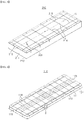
- FIG. 3 is a view of a secondary insulation panel of the LNG storage tank according to the present invention
- FIG. 4 is a view of a primary insulation panel of the LNG storage tank according to the present invention.
- the LNG storage tank according to the present invention has a structure in which a secondary insulation wall 200 constituted of multiple secondary insulation panels 210 and a primary insulation wall 100 constituted of multiple primary insulation panels 110 are sequentially stacked on an inner wall of a hull.
- a secondary sealing wall 400 may be interposed between the secondary insulation wall 200 and the primary insulation wall 100 and a primary sealing wall (not shown) may be disposed on an upper side of the primary insulation wall 100.
- a primary sealing wall (not shown) may be disposed on an upper side of the primary insulation wall 100.
- the primary sealing wall is not shown.
- the primary and secondary insulation panels 110, 210 may be manufactured as unit panels each having a hexahedral shape having a width-to-length ratio of about 1:3, preferably as unit panels having a size of about 1 m x 3 m, without being limited thereto.
- the primary insulation panel 110 may be a sandwich panel in which plywood sheets 112, 113 are bonded to an upper or lower surface of an insulator 111 formed of polyurethane foam (PUF) or to both upper and lower surfaces of the insulator 111.
- PEF polyurethane foam
- the secondary insulation panel 210 may be a sandwich panel in which plywood sheets 212, 213 are bonded to an upper or lower surface of an insulator 211 formed of polyurethane foam (PUF) or to both upper and lower surfaces of the insulator 111.
- PEF polyurethane foam
- the primary and secondary insulation panels 110, 210 constituting the primary and secondary insulation walls 100, 200 are formed of rigid polyurethane foam (RPUF), which has higher strength than general polyurethane foam, in order to form the secondary sealing wall 400 with flat Invar membranes, as described below.
- RPUF rigid polyurethane foam
- the secondary insulation panels 210 may be secured to an inner wall of the hull by a bonding agent, such as mastic, or studs, and the secondary insulation panel 110 may be closely coupled to an upper side of the secondary sealing wall 400 by fixing devices 300 disposed on the upper side thereof, with the secondary sealing wall 400 interposed between the primary insulation panels 110 and the secondary insulation panels 210.
- a bonding agent such as mastic, or studs
- the primary sealing wall directly contacts LNG to seal the LNG and may be constituted of multiple stainless steel (SUS) membranes having corrugations formed towards the interior of the storage tank to absorb contraction due to an extremely low temperature inside the storage tank.
- SUS stainless steel
- the primary sealing wall (not shown) may be constituted of multiple unit membranes and may be sealed by welding the multiple unit membranes to anchor strips on the primary insulation panels 110 so as not to generate a gap therebetween.
- the secondary sealing wall 400 may be constituted of Invar membranes.
- the secondary sealing wall 400 may be constituted of multiple Invar strakes and may be sealed by welding the multiple Invar strakes to tongue members on the secondary insulation panels 210 so as not to generate a gap therebetween.
- the Invar strakes refer to band-shaped metal plates having a narrow width.
- each of the primary and secondary insulation walls 100, 200 is realized in the form of an insulation panel in which plywood sheets are bonded to an upper surface and/or a lower surface of polyurethane foam, and the secondary sealing wall 400 is constituted of flat invar membranes.
- the flat Invar membrane has a low coefficient of thermal contraction
- the flat Invar membrane is not suitable for a panel type insulating system in which insulation panels are formed of polyurethane foam.
- the insulation wall supporting the membranes is required to be constituted of insulating boxes exhibiting low thermal contraction and having high rigidity, as in a typical NO 96 type storage tank.
- the LNG storage tank has a structure for reinforcing the secondary insulation wall 200, whereby the secondary insulation wall 200 can be constituted of the insulation panels formed of the polyurethane foam and the secondary sealing wall 400 can be constituted of the flat Invar membranes.
- a corner portion of the storage tank is provided with a transverse connector (not shown) which supports both ends of the secondary sealing wall 400.
- the transverse connector is a grid structure disposed along an edge of each of front and rear walls of the storage tank.
- the transverse connector is welded at one end thereof to an anchoring bar provided to an inner wall of the hull to be secured to a corner of the storage tank while supporting both ends of each of the primary and secondary sealing walls 400 at the other end thereof, thereby enabling transfer of load to the hull when the load is applied to the transverse connector.
- the transverse connector is preferably formed of an Invar material having high rigidity and an insulating box having high rigidity may be disposed inside the transverse connector and between the transverse connector and the hull to support the transverse connector.
- the insulating box may be prepared by filling a plywood box with perlite powder.
- the secondary insulation wall 200 which supports the secondary sealing wall 400 constituted of the flat Invar membranes, can be constituted of insulation panels having lower rigidity than the insulating boxes.
- a welding line can be formed linearly upon installation of the secondary sealing wall 400 on the secondary insulation wall 200, thereby enabling improvement in productivity through automation of welding.
- each of the primary and secondary insulation walls 100, 200 is constituted of the insulation panels formed of the polyurethane foam, thereby improving insulating performance.
- the LNG storage tank according to the present invention can reduce the thickness of the primary insulation wall to about 40% or more and the thickness of the secondary insulation wall to about 20% or more, as compared with a typical NO 96 type storage tank in which the insulation walls are provided in the form of insulating boxes, while securing the same insulating effects as the typical NO 96 type storage tank.
- the LNG storage tank according to the present invention has a structure in which the secondary insulation panels 210 intersect with the primary insulation panels 110 disposed on the secondary insulation panels 210.
- the primary insulation panels 110 may be disposed to intersect with the secondary insulation panels 210 such that a corner of each of the primary insulation panels 110 is placed at the center of each of the secondary insulation panels 210, whereby each primary insulation panel 110 is disposed to straddle upper surfaces of four secondary insulation panels 210.
- the fixing devices 300 adapted to secure the primary insulation panels 110 to the secondary insulation panels 210 may be disposed inside edges on the upper surfaces of the secondary insulation panels 210, for example, at the center of each of the upper surfaces thereof.
- one fixing device 300 may be disposed at the center of the insulation panel 210 and other fixing devices 300 may be arranged to be separated from the fixing device 300 at the center of the insulation panel 210 by the same distance in a longitudinal direction.
- the fixing device 300 is disposed on a central line C on the secondary insulation panels 210 in a width direction to minimize displacement of the secondary insulation panels 210 in the width direction due to stress applied to the secondary insulation panels 210 and slits 214 may be formed at places separated forwards and backwards from the fixing devices 300 by the same distance to minimize displacement of the fixing devices 300 in the longitudinal direction.
- each of the primary insulation panels 110 may be provided with securing portions S for coupling to the fixing device 300 at vertical edges on lateral sides of the primary insulation panel 110 including four corners of the primary insulation panel 110.
- the securing portions S may be arranged at constant intervals in the longitudinal direction of the primary insulation panels 110.
- Each of the securing portions S may be provided as a groove having a semicircular or sector-shaped cross-section and may be compressed by fastening a nut to a stud of the fixing device, with the stud of the fixing device 300 inserted into the securing portion S so as to pass therethrough, whereby the primary insulation panels 110 can be brought into close contact with the secondary insulation panels 210.
- This structure will be described below in more detail.
- three fixing devices 300 are disposed on the secondary insulation panels 210 and eight securing portions S are disposed at vertical edges of the primary insulation panels 110.
- the securing portions S formed on four primary insulation panels 110 may be coupled together to the fixing device 300 disposed at the center of the secondary insulation panels 210 and the securing portions S formed on two primary insulation panels 110 may be coupled together to the fixing devices 300 separated from the center of each of the secondary insulation panels 210.
- adjacent primary insulation panels 110 may share the fixing devices 300 interposed therebetween and eight points for supporting the primary insulation panels 110 may be guaranteed merely through three fixing devices 300 provided to one secondary insulation panel 210.
- the securing portions S for coupling to the fixing devices 300 are provided to the corners of the primary insulation panels 110, whereby the points for supporting the primary insulation panels 110 can be secured as many as possible even with a small number of fixing devices 300, thereby improving stability of the support structure and productivity of the insulation panels.
- Reference numeral 215 indicates insertion grooves formed to receive the tongue members to which the Invar strakes constituting the secondary sealing wall 400 are welded and reference numeral 115 indicates insertion grooves formed to receive the tongue members received in the insertion grooves 215 and edges of the Invar strakes welded to the tongue members.
- Reference numeral 114 indicates multiple slits formed on the primary insulation panels 110 to distribute stress concentration caused by thermal contraction and reference numeral 116 indicates anchor strips disposed for welding of the primary sealing wall.
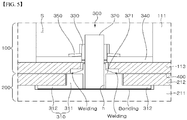
- FIG. 5 is a schematic view of an insulation wall fixing device of the LNG storage tank according to the present invention.
- the structure of the insulation wall fixing device 300 of the LNG storage tank according to the present invention will be described.
- the primary insulation wall 100 includes a primary insulator 111 and a primary lower protective plate 113
- the secondary insulation wall 200 includes a secondary insulator 211 and a secondary upper protective plate 212.
- both the primary insulator 111 and the secondary insulator 211 may be formed of polyurethane foam (PUF)
- both the primary lower protective plate 113 and the secondary upper protective plate 212 may be formed of plywood sheets.
- the secondary upper protective plate 212 of the secondary insulation wall 200 may be formed with a hole corresponding to a socket body 311 described below and the primary insulation wall 100 may be formed with the securing portions S for coupling to the fixing devices 300.
- the securing portion S provides a space for receiving an upper portion of the fixing device 300.
- the insulation wall fixing device 300 of the LNG storage tank includes a base socket 310 disposed on the secondary insulation wall 200; a stud 320 screwed to the base socket 310 and having an upper end inserted into the securing portion S formed on the primary insulation wall 100; and a lock nut 330 coupled to the stud 320 inserted into the securing portion S.
- the base socket 310 includes a socket body 311 which constitutes a body of the base socket 310, and a socket flange 312 protruding from a lower circumference of the socket body 311 to be inserted into a space between a groove formed on an upper surface of the secondary insulator 211 and the secondary upper protective plate 212.
- the base socket 310 may be mounted on the groove formed on the upper surface of the secondary insulator 211 by bonding a lower surface of the base socket 310 to an upper surface of the groove.
- An upper surface of the socket body 311 may be flush with an upper surface of the secondary upper protective plate 212 and an upper surface of the socket flange 312 may be flush with the upper surface of the secondary insulator 211. That is, as shown in the drawings, the base socket 310 may have a cross-section stepped by the socket body 311 and the socket flange 312.
- the socket flange 312 is inserted into the space between the groove formed on the upper surface of the secondary insulator 211 and the secondary upper protective plate 212 such that the upper surface of the socket flange 312 supports an end of the secondary upper protective plate 212.
- the socket flange 312 allows the secondary upper protective plate 212 to endure load applied from the fixing devices 300 by supporting the secondary upper protective plate 212 and the secondary upper protective plate 212 is not cut in the thickness direction and thus can endure load while maintaining strength thereof.
- the insulation wall fixing device can secure higher fastening strength than a typical fastening mechanism (see FIG. 1 ) and can facilitate strength reinforcement through adjustment of the size or thickness of the base socket 310, the thickness of the secondary upper protective plate 212, and the like, as needed.
- the base socket 310 may be formed of stainless steel (SUS).
- the base socket 310 may be secured to an upper side of the secondary insulation wall 200 by placing the base socket 310 on the groove formed on the upper surface of the secondary insulator 211, followed by bonding the base socket 31 to the secondary upper protective plate 212 such that the secondary upper protective plate 212 is placed on the upper surface of the secondary insulator 211 and the upper surface of the socket flange 312.
- the insulation wall fixing device 300 may be stored with the base socket 310 disposed on the secondary insulation wall 200, thereby improving productivity through omission of riveting and bonding operations in on-board operation.
- the stud 320 may be a collar stud and may include a vane 321 protruding from a body of the stud 320 and mounted on an upper surface of the socket body 311.
- the vane 321 extends from the body of the stud 320 to be slanted downwards therefrom such that a distal end of the vane 321 is placed on the upper surface of the socket body 311.
- the secondary sealing wall 400 may be coupled to the distal end of the vane 321 by welding. That is, as shown in the drawings, the secondary sealing wall 400 may be welded to the distal end of the vane 321 to be placed between the secondary insulation wall 200 and the primary insulation wall 100.
- a contact region between the secondary sealing wall 400 and the vane 321 is formed on the upper surface of the socket body 311 and the secondary sealing wall 400 is welded to the vane 321 in the contact region therebetween.
- welding of the secondary sealing wall 400 is performed on the upper surface of the socket body 311, thereby preventing burn damage on the secondary upper protective plate 212 of the secondary insulation wall 210.
- the vane 321 is welded to the secondary sealing wall 400 to secure water tightness between the base socket 310 and the stud 320, whereby a stud fastening hole h of the base socket 310 can be formed in the form of a through-hole or a blind hole.
- the stud fastening hole h of the base socket 310 is preferably formed in a blind hole shape.
- the insulation wall fixing device 300 of the LNG storage tank according to the present invention may further include a flat washer 340 inserted into the stud 320 through an upper portion of the stud 320 and supported by the primary lower protective plate 113 in a region of the securing portion S; and a spring washer 350 disposed on an upper surface of the flat washer 340 and supporting the lock nut 330.
Landscapes
- Engineering & Computer Science (AREA)
- Mechanical Engineering (AREA)
- Physics & Mathematics (AREA)
- Thermal Sciences (AREA)
- General Engineering & Computer Science (AREA)
- Chemical & Material Sciences (AREA)
- Combustion & Propulsion (AREA)
- Ocean & Marine Engineering (AREA)
- Filling Or Discharging Of Gas Storage Vessels (AREA)
Abstract
Description
- The present invention relates to an insulation wall fixing device for liquefied natural gas storage tanks, and more particularly to an insulation wall fixing device for liquefied natural gas storage tanks, which couples a primary insulation wall to a secondary insulation wall disposed for insulation of liquefied natural gas.
- Natural gas is transported in a gaseous state via onshore or offshore gas pipelines, or is transported in a liquid state, that is, in the form of liquefied natural gas (LNG) to a distant destination by an LNG carrier. LNG is obtained by cooling natural gas to a cryogenic temperature (about -163°C) and has a volume of about 1/600 that of natural gas in a gaseous state. Thus, LNG is suited to long distance transport by sea.
- Structures for transporting or storing LNG, such as an LNG carrier designed to carry LNG by sea to an onshore consumer site, are equipped with a storage tank that can withstand cryogenic temperatures of LNG (commonly referred to as "cargo hold").
- Such an LNG storage tank is divided into an independent storage tank and a membrane type storage tank depending on whether a load of cargo is directly applied to an insulator. Generally, the membrane type storage tank is classified into a GTT NO 96 storage tank and a MARK III storage tank, and the independent storage tank is classified into a MOSS storage tank and an IHI-SPB storage tank.
- The NO 96 storage tank comprises primary and secondary sealing walls constituted of 0.5 mm to 0.7 mm thick Invar (Ni content: 36%) membranes and primary and secondary insulation walls provided in the form of insulating boxes fabricated by filling a plywood box with an insulator, such as perlite powder.
- Since the primary and secondary sealing walls of the NO 96 storage tank have almost the same degree of liquid tightness and strength, it is possible to safely support cargo for a considerable period of time with only the secondary sealing wall even upon leakage of the primary sealing wall.
- In addition, since the insulation walls of the NO 96 storage tank are provided in the form of wood boxes filled with an insulator, the NO 96 storage tank has high compressive strength and rigidity and thus can secure high levels of weldability and welding automation, as compared with the MARK III storage tank.
- The MARK III storage tank comprises a primary sealing wall constituted of 1.2 mm thick stainless steel (SUS) membranes, a secondary sealing wall constituted of triplex sheets, and primary and secondary insulation walls provided in the form of insulation panels fabricated by bonding plywood to an upper or lower surface of polyurethane foam.
- The primary sealing wall of the MARK III storage tank has corrugations to absorb thermal contraction caused by LNG at cryogenic temperatures. The corrugations can prevent occurrence of excessive stress on the membranes by absorbing deformation of the membranes.
- The MARK III storage tank has disadvantages in terms of installation/fabrication due to a low level of automation of the primary sealing wall, which is constituted of corrugated membranes. However, since the stainless steel membrane and the triplex sheet are less expensive and easier to construct than the Invar membrane and the polyurethane foam has good insulation performance, the MARK III storage tank is widely used.
- The primary insulation wall of the membrane-type storage tank is coupled to a fixing device disposed on an upper surface of the secondary insulation wall to be securely mounted on the upper surface of the secondary insulation wall.
-
FIG. 1 is a schematic view of a typical insulation wall fixing device for LNG storage tanks. - Specifically,
FIG. 1(a) shows mechanical coupling between abase socket 10 for coupling to a primary insulation wall and an upperprotective plate 20 of a secondary insulation wall through rivets,FIG. 1(b) shows coupling between thebase socket 10 and the upperprotective plate 20 of the secondary insulation wall through bonding, andFIG. 1(c) shows coupling between thebase socket 10 and the upperprotective plate 20 of the secondary insulation wall through bonding after cutting a portion of a lower surface of the upperprotective plate 20 of the secondary insulation wall. Here,reference numeral 30 denotes an insulator disposed inside the secondary insulation wall. - Such a typical insulation wall securing device requires cutting of a substantial portion of the upper
protective plate 20 for securing thebase socket 10, thereby causing reduction in strength of the upperprotective plate 20 of the secondary insulation wall. - Although not shown in the drawings, welding of a secondary sealing wall is performed on the
base socket 10, thereby causing burn damage of the upperprotective plate 20 due to welding heat. Therefore, there is a need for the provision of a solution to these problems. - It is an aspect of the present invention to provide an insulation wall fixing device for LNG storage tanks, which can improve strength of a coupling region between a primary insulation wall and a secondary insulation wall by improving a fixing device for coupling the primary insulation wall and the secondary insulation wall.
- In accordance with one aspect of the present invention, there is provided an insulation wall fixing device for an LNG storage tank including: a primary insulation wall primarily insulating liquefied natural gas; a secondary insulation wall disposed under the primary insulation wall and secondarily insulating the liquefied natural gas, the secondary insulation wall including a secondary insulator and a secondary upper protective plate disposed on the secondary insulator; and a fixing device coupling the primary insulation wall to the secondary insulation wall, the fixing device including: a base socket having a lower circumference protruding in a step shape and a stud coupled to the base socket, wherein the base socket has a lower surface mounted on a groove formed on an upper surface of the secondary insulator and the lower circumference of the base socket supports a lower surface of the secondary upper protective plate.
- The base socket may include a socket body constituting a body of the base socket and a socket flange protruding in a step shape from the socket body, an upper surface of the socket flange being flush with an upper surface of the secondary insulator, and the secondary upper protective plate may be disposed to sit on the upper surfaces of the secondary insulator and the socket flange.
- An upper surface of the socket body may be flush with an upper surface of the secondary upper protective plate.
- The secondary insulator may be formed of polyurethane foam (PUF) and the secondary upper protective plate may be formed of plywood.
- The base socket may be bonded to the secondary insulator.
- The fixing device may further include a secondary sealing wall interposed between the primary insulation wall and the secondary insulation wall; and a vane protruding from a body of the stud such that a lower surface of the vane is mounted on an upper surface of the socket body, wherein an adjoining region between the secondary sealing wall and the vane is disposed on the upper surface of the socket body.
- The secondary sealing wall may be welded to the vane in the adjoining region therebetween.
- In accordance with another aspect of the present invention, there is provided an insulation wall fixing device for securing a primary insulation wall to a secondary insulation wall in an LNG storage tank, the fixing device comprising: a base socket mounted on a groove formed on an upper surface of a secondary insulator of the secondary insulation wall, wherein a lower end of the base socket protrudes in a step shape such that a step portion of the base socket supports a lower surface of an upper protective plate of the secondary insulation wall.
- An uppermost surface of the base socket may be flush with an upper surface of the upper protective plate, a step surface of the step portion protruding from the base socket may be flush with the upper surface of the secondary insulator, and the base socket may be formed with a fastening hole through which a stud is coupled to the primary insulation wall.
- The stud may include a vane protruding therefrom to be coupled to a secondary sealing wall disposed between the primary insulation wall and the secondary insulation wall, and the secondary sealing wall may be welded to the vane on the uppermost surface of the base socket.
- In an insulation wall fixing device for LNG storage tanks according to the present invention, an upper surface of a socket flange supports an upper protective plate of a secondary insulation wall, whereby the upper protective plate can endure load applied thereto while maintaining strength thereof, and a cut region of the upper protective plate can be minimized, whereby the fixing device can have higher strength than a typical insulation wall fixing device.
- In addition, according to the present invention, welding of the secondary sealing wall is performed on an upper surface of the base socket, thereby preventing burn damage to the secondary upper protective plate due to welding heat.
- Furthermore, the insulation wall fixing device according to the present invention can improve productivity through reduction in on-board labor.
-
-
FIG. 1 is a schematic view of a typical insulation wall fixing device for LNG storage tanks. -
FIG. 2 is a schematic view of an insulating structure of an LNG storage tank according to the present invention. -
FIG. 3 is a view of a secondary insulation panel of the LNG storage tank according to the present invention. -
FIG. 4 is a view of a primary insulation panel of the LNG storage tank according to the present invention. -
FIG. 5 is a schematic view of an insulation wall fixing device of the LNG storage tank according to the present invention. - The above and other aspects, features, and advantages of the present invention will become apparent from the detailed description of the following embodiments in conjunction with the accompanying drawings.
- Hereinafter, embodiments of the present invention will be described in detail. Like components will be denoted by like reference numerals throughout the specification.
- Herein, the terms "primary" and "secondary" are used to distinguish components providing primary sealing or insulation to an LNG storage tank from components providing secondary sealing or insulation to the LNG storage tank.
- In addition, as used herein to describe components of a tank, the term "upper" or "above" refers to an inward direction of the tank, regardless of the direction of gravity, and the term "lower" or "below" refers to an outward direction of the tank, regardless of the direction of gravity.
-
FIG. 2 is a schematic view of an insulating structure of an LNG storage tank according to the present invention,FIG. 3 is a view of a secondary insulation panel of the LNG storage tank according to the present invention, andFIG. 4 is a view of a primary insulation panel of the LNG storage tank according to the present invention. - Referring to
FIG. 2 to FIG. 4 , the LNG storage tank according to the present invention has a structure in which asecondary insulation wall 200 constituted of multiplesecondary insulation panels 210 and aprimary insulation wall 100 constituted of multipleprimary insulation panels 110 are sequentially stacked on an inner wall of a hull. - A
secondary sealing wall 400 may be interposed between thesecondary insulation wall 200 and theprimary insulation wall 100 and a primary sealing wall (not shown) may be disposed on an upper side of theprimary insulation wall 100. For convenience of description, the primary sealing wall is not shown. - The primary and
secondary insulation panels - The
primary insulation panel 110 may be a sandwich panel in whichplywood sheets insulator 111 formed of polyurethane foam (PUF) or to both upper and lower surfaces of theinsulator 111. - Likewise, the
secondary insulation panel 210 may be a sandwich panel in whichplywood sheets insulator 211 formed of polyurethane foam (PUF) or to both upper and lower surfaces of theinsulator 111. - Preferably, the primary and
secondary insulation panels secondary insulation walls secondary sealing wall 400 with flat Invar membranes, as described below. - The
secondary insulation panels 210 may be secured to an inner wall of the hull by a bonding agent, such as mastic, or studs, and thesecondary insulation panel 110 may be closely coupled to an upper side of thesecondary sealing wall 400 byfixing devices 300 disposed on the upper side thereof, with thesecondary sealing wall 400 interposed between theprimary insulation panels 110 and thesecondary insulation panels 210. - The primary sealing wall (not shown) directly contacts LNG to seal the LNG and may be constituted of multiple stainless steel (SUS) membranes having corrugations formed towards the interior of the storage tank to absorb contraction due to an extremely low temperature inside the storage tank.
- The primary sealing wall (not shown) may be constituted of multiple unit membranes and may be sealed by welding the multiple unit membranes to anchor strips on the
primary insulation panels 110 so as not to generate a gap therebetween. - The
secondary sealing wall 400 may be constituted of Invar membranes. - The
secondary sealing wall 400 may be constituted of multiple Invar strakes and may be sealed by welding the multiple Invar strakes to tongue members on thesecondary insulation panels 210 so as not to generate a gap therebetween. The Invar strakes refer to band-shaped metal plates having a narrow width. - In the LNG storage tank according to the present invention, each of the primary and
secondary insulation walls secondary sealing wall 400 is constituted of flat invar membranes. - Typically, since the flat Invar membrane has a low coefficient of thermal contraction, the flat Invar membrane is not suitable for a panel type insulating system in which insulation panels are formed of polyurethane foam. In order to allow application of the flat Invar membranes to the panel type insulating system, the insulation wall supporting the membranes is required to be constituted of insulating boxes exhibiting low thermal contraction and having high rigidity, as in a typical NO 96 type storage tank.
- However, according to the present invention, the LNG storage tank has a structure for reinforcing the
secondary insulation wall 200, whereby thesecondary insulation wall 200 can be constituted of the insulation panels formed of the polyurethane foam and thesecondary sealing wall 400 can be constituted of the flat Invar membranes. - According to the present invention, in order to reinforce the
secondary insulation wall 200, a corner portion of the storage tank is provided with a transverse connector (not shown) which supports both ends of thesecondary sealing wall 400. - The transverse connector is a grid structure disposed along an edge of each of front and rear walls of the storage tank. The transverse connector is welded at one end thereof to an anchoring bar provided to an inner wall of the hull to be secured to a corner of the storage tank while supporting both ends of each of the primary and
secondary sealing walls 400 at the other end thereof, thereby enabling transfer of load to the hull when the load is applied to the transverse connector. - The transverse connector is preferably formed of an Invar material having high rigidity and an insulating box having high rigidity may be disposed inside the transverse connector and between the transverse connector and the hull to support the transverse connector. The insulating box may be prepared by filling a plywood box with perlite powder.
- According to the present invention, since the transverse connector transfers part of load applied to the sealing walls to the hull, the
secondary insulation wall 200, which supports thesecondary sealing wall 400 constituted of the flat Invar membranes, can be constituted of insulation panels having lower rigidity than the insulating boxes. - As a result, according to the present invention, a welding line can be formed linearly upon installation of the
secondary sealing wall 400 on thesecondary insulation wall 200, thereby enabling improvement in productivity through automation of welding. - Further, according to the present invention, each of the primary and
secondary insulation walls - The LNG storage tank according to the present invention has a structure in which the
secondary insulation panels 210 intersect with theprimary insulation panels 110 disposed on thesecondary insulation panels 210. - Referring to
FIG. 2 , theprimary insulation panels 110 may be disposed to intersect with thesecondary insulation panels 210 such that a corner of each of theprimary insulation panels 110 is placed at the center of each of thesecondary insulation panels 210, whereby eachprimary insulation panel 110 is disposed to straddle upper surfaces of foursecondary insulation panels 210. - To achieve intersection between the
primary insulation panels 110 and thesecondary insulation panels 210, the fixingdevices 300 adapted to secure theprimary insulation panels 110 to thesecondary insulation panels 210 may be disposed inside edges on the upper surfaces of thesecondary insulation panels 210, for example, at the center of each of the upper surfaces thereof. - Referring to
FIG. 3 , onefixing device 300 may be disposed at the center of theinsulation panel 210 and other fixingdevices 300 may be arranged to be separated from the fixingdevice 300 at the center of theinsulation panel 210 by the same distance in a longitudinal direction. - The fixing
device 300 is disposed on a central line C on thesecondary insulation panels 210 in a width direction to minimize displacement of thesecondary insulation panels 210 in the width direction due to stress applied to thesecondary insulation panels 210 and slits 214 may be formed at places separated forwards and backwards from the fixingdevices 300 by the same distance to minimize displacement of the fixingdevices 300 in the longitudinal direction. - Further, each of the
primary insulation panels 110 may be provided with securing portions S for coupling to thefixing device 300 at vertical edges on lateral sides of theprimary insulation panel 110 including four corners of theprimary insulation panel 110. The securing portions S may be arranged at constant intervals in the longitudinal direction of theprimary insulation panels 110. - Each of the securing portions S may be provided as a groove having a semicircular or sector-shaped cross-section and may be compressed by fastening a nut to a stud of the fixing device, with the stud of the fixing
device 300 inserted into the securing portion S so as to pass therethrough, whereby theprimary insulation panels 110 can be brought into close contact with thesecondary insulation panels 210. This structure will be described below in more detail. - In this embodiment, three fixing
devices 300 are disposed on thesecondary insulation panels 210 and eight securing portions S are disposed at vertical edges of theprimary insulation panels 110. - According to this embodiment, the securing portions S formed on four
primary insulation panels 110 may be coupled together to thefixing device 300 disposed at the center of thesecondary insulation panels 210 and the securing portions S formed on twoprimary insulation panels 110 may be coupled together to the fixingdevices 300 separated from the center of each of thesecondary insulation panels 210. - As such, according to this embodiment, adjacent
primary insulation panels 110 may share the fixingdevices 300 interposed therebetween and eight points for supporting theprimary insulation panels 110 may be guaranteed merely through three fixingdevices 300 provided to onesecondary insulation panel 210. - That is, according to the present invention, the securing portions S for coupling to the fixing
devices 300 are provided to the corners of theprimary insulation panels 110, whereby the points for supporting theprimary insulation panels 110 can be secured as many as possible even with a small number of fixingdevices 300, thereby improving stability of the support structure and productivity of the insulation panels. -
Reference numeral 215 indicates insertion grooves formed to receive the tongue members to which the Invar strakes constituting thesecondary sealing wall 400 are welded andreference numeral 115 indicates insertion grooves formed to receive the tongue members received in theinsertion grooves 215 and edges of the Invar strakes welded to the tongue members. -
Reference numeral 114 indicates multiple slits formed on theprimary insulation panels 110 to distribute stress concentration caused by thermal contraction andreference numeral 116 indicates anchor strips disposed for welding of the primary sealing wall. -
FIG. 5 is a schematic view of an insulation wall fixing device of the LNG storage tank according to the present invention. Hereinafter, the structure of the insulationwall fixing device 300 of the LNG storage tank according to the present invention will be described. - As shown in
FIG. 5 , theprimary insulation wall 100 includes aprimary insulator 111 and a primary lowerprotective plate 113, and thesecondary insulation wall 200 includes asecondary insulator 211 and a secondary upperprotective plate 212. As described above, both theprimary insulator 111 and thesecondary insulator 211 may be formed of polyurethane foam (PUF), and both the primary lowerprotective plate 113 and the secondary upperprotective plate 212 may be formed of plywood sheets. - The secondary upper
protective plate 212 of thesecondary insulation wall 200 may be formed with a hole corresponding to asocket body 311 described below and theprimary insulation wall 100 may be formed with the securing portions S for coupling to the fixingdevices 300. The securing portion S provides a space for receiving an upper portion of the fixingdevice 300. - Referring to
FIG. 5 , the insulationwall fixing device 300 of the LNG storage tank according to the present invention includes abase socket 310 disposed on thesecondary insulation wall 200; astud 320 screwed to thebase socket 310 and having an upper end inserted into the securing portion S formed on theprimary insulation wall 100; and alock nut 330 coupled to thestud 320 inserted into the securing portion S. - The
base socket 310 includes asocket body 311 which constitutes a body of thebase socket 310, and asocket flange 312 protruding from a lower circumference of thesocket body 311 to be inserted into a space between a groove formed on an upper surface of thesecondary insulator 211 and the secondary upperprotective plate 212. - The
base socket 310 may be mounted on the groove formed on the upper surface of thesecondary insulator 211 by bonding a lower surface of thebase socket 310 to an upper surface of the groove. - An upper surface of the
socket body 311 may be flush with an upper surface of the secondary upperprotective plate 212 and an upper surface of thesocket flange 312 may be flush with the upper surface of thesecondary insulator 211. That is, as shown in the drawings, thebase socket 310 may have a cross-section stepped by thesocket body 311 and thesocket flange 312. - The
socket flange 312 is inserted into the space between the groove formed on the upper surface of thesecondary insulator 211 and the secondary upperprotective plate 212 such that the upper surface of thesocket flange 312 supports an end of the secondary upperprotective plate 212. - According to the present invention, the
socket flange 312 allows the secondary upperprotective plate 212 to endure load applied from the fixingdevices 300 by supporting the secondary upperprotective plate 212 and the secondary upperprotective plate 212 is not cut in the thickness direction and thus can endure load while maintaining strength thereof. - Accordingly, the insulation wall fixing device according to the present invention can secure higher fastening strength than a typical fastening mechanism (see
FIG. 1 ) and can facilitate strength reinforcement through adjustment of the size or thickness of thebase socket 310, the thickness of the secondary upperprotective plate 212, and the like, as needed. - The
base socket 310 may be formed of stainless steel (SUS). - The
base socket 310 may be secured to an upper side of thesecondary insulation wall 200 by placing thebase socket 310 on the groove formed on the upper surface of thesecondary insulator 211, followed by bonding the base socket 31 to the secondary upperprotective plate 212 such that the secondary upperprotective plate 212 is placed on the upper surface of thesecondary insulator 211 and the upper surface of thesocket flange 312. - That is, the insulation
wall fixing device 300 according to the present invention may be stored with thebase socket 310 disposed on thesecondary insulation wall 200, thereby improving productivity through omission of riveting and bonding operations in on-board operation. - According to the present invention, the
stud 320 may be a collar stud and may include avane 321 protruding from a body of thestud 320 and mounted on an upper surface of thesocket body 311. - The
vane 321 extends from the body of thestud 320 to be slanted downwards therefrom such that a distal end of thevane 321 is placed on the upper surface of thesocket body 311. - Here, the
secondary sealing wall 400 may be coupled to the distal end of thevane 321 by welding. That is, as shown in the drawings, thesecondary sealing wall 400 may be welded to the distal end of thevane 321 to be placed between thesecondary insulation wall 200 and theprimary insulation wall 100. - According to the present invention, a contact region between the
secondary sealing wall 400 and thevane 321 is formed on the upper surface of thesocket body 311 and thesecondary sealing wall 400 is welded to thevane 321 in the contact region therebetween. - Accordingly, according to the present invention, welding of the
secondary sealing wall 400 is performed on the upper surface of thesocket body 311, thereby preventing burn damage on the secondary upperprotective plate 212 of thesecondary insulation wall 210. - In addition, in the structure wherein the
stud 320 is provided in the form of the collar stud including thevane 321 as described above, thevane 321 is welded to thesecondary sealing wall 400 to secure water tightness between thebase socket 310 and thestud 320, whereby a stud fastening hole h of thebase socket 310 can be formed in the form of a through-hole or a blind hole. - If the
stud 320 is a typical stud, water tightness cannot be secured in a gap for fastening between thebase socket 310 and thestud 320. In this case, the stud fastening hole h of thebase socket 310 is preferably formed in a blind hole shape. - The insulation
wall fixing device 300 of the LNG storage tank according to the present invention may further include aflat washer 340 inserted into thestud 320 through an upper portion of thestud 320 and supported by the primary lowerprotective plate 113 in a region of the securing portion S; and aspring washer 350 disposed on an upper surface of theflat washer 340 and supporting thelock nut 330. - Although some embodiments have been described herein, it should be understood that these embodiments are provided for illustration only and are not to be construed in any way as limiting the present invention, and that various modifications, changes, alterations, and equivalent embodiments can be made by those skilled in the art without departing from the spirit and scope of the invention. Therefore, the scope of the present invention should be defined by the appended claims and equivalents thereto.
Claims (10)
- An insulation wall fixing device for a liquefied natural gas (LNG) storage tank, the LNG storage tank comprising:a primary insulation wall primarily insulating liquefied natural gas;a secondary insulation wall disposed under the primary insulation wall and secondarily insulating the liquefied natural gas, the secondary insulation wall comprising a secondary insulator and a secondary upper protective plate disposed on the secondary insulator; anda fixing device coupling the primary insulation wall to the secondary insulation wall, the fixing device comprising:a base socket having a lower circumference protruding in a step shape; anda stud coupled to the base socket,wherein the base socket has a lower surface mounted on a groove formed on an upper surface of the secondary insulator and the lower circumference of the base socket supports a lower surface of the secondary upper protective plate.
- The insulation wall fixing device for the LNG storage tank according to claim 1, wherein:the base socket comprises a socket body constituting a body of the base socket and a socket flange protruding in a step shape from the socket body;an upper surface of the socket flange is flush with an upper surface of the secondary insulator; andthe secondary upper protective plate is disposed to straddle the upper surface of the secondary insulator and the upper surface of the socket flange.
- The insulation wall fixing device for the LNG storage tank according to claim 2, wherein an upper surface of the socket body is flush with an upper surface of the secondary upper protective plate.
- The insulation wall fixing device for the LNG storage tank according to claim 3, wherein the secondary insulator is formed of polyurethane foam (PUF) and the secondary upper protective plate is formed of plywood.
- The insulation wall fixing device for the LNG storage tank according to claim 4, wherein the base socket is coupled to the secondary insulator through bonding.
- The insulation wall fixing device for the LNG storage tank according to claim 3, further comprising:a secondary sealing wall interposed between the primary insulation wall and the secondary insulation wall; anda vane protruding from a body of the stud such that a lower surface of the vane is mounted on an upper surface of the socket body,wherein an adjoining region between the secondary sealing wall and the vane is disposed on the upper surface of the socket body.
- The insulation wall fixing device for the LNG storage tank according to claim 6, wherein the secondary sealing wall is welded to the vane in the adjoining region therebetween.
- An insulation wall fixing device for securing a primary insulation wall to a secondary insulation wall in an LNG storage tank, comprising:
a base socket mounted on a groove formed on an upper surface of a secondary insulator of the secondary insulation wall, the base socket having a lower circumference protruding in a step shape such that a step portion of the base socket supports a lower surface of an upper protective plate of the secondary insulation wall. - The fixing device according to claim 8, wherein:an uppermost surface of the base socket is flush with an upper surface of the upper protective plate;a step surface of the step portion protruding from the base socket is flush with the upper surface of the secondary insulator; andthe base socket is formed with a fastening hole through which a stud is coupled to the primary insulation wall.
- The fixing device according to claim 9, wherein the stud comprises a vane protruding therefrom to be coupled to a secondary sealing wall disposed between the primary insulation wall and the secondary insulation wall, and the secondary sealing wall is welded to the vane on the uppermost surface of the base socket.
Applications Claiming Priority (2)
| Application Number | Priority Date | Filing Date | Title |
|---|---|---|---|
| KR1020180166239A KR102158648B1 (en) | 2018-12-20 | 2018-12-20 | Insulation wall securing device for lng storage tank |
| PCT/KR2019/018049 WO2020130650A1 (en) | 2018-12-20 | 2019-12-18 | Insulation wall fixing device for liquefied natural gas storage tank |
Publications (4)
| Publication Number | Publication Date |
|---|---|
| EP3901026A1 true EP3901026A1 (en) | 2021-10-27 |
| EP3901026A4 EP3901026A4 (en) | 2022-08-31 |
| EP3901026C0 EP3901026C0 (en) | 2024-08-21 |
| EP3901026B1 EP3901026B1 (en) | 2024-08-21 |
Family
ID=71102207
Family Applications (1)
| Application Number | Title | Priority Date | Filing Date |
|---|---|---|---|
| EP19897777.9A Active EP3901026B1 (en) | 2018-12-20 | 2019-12-18 | Insulation wall fixing device for liquefied natural gas storage tank |
Country Status (5)
| Country | Link |
|---|---|
| EP (1) | EP3901026B1 (en) |
| KR (1) | KR102158648B1 (en) |
| CN (1) | CN113474248B (en) |
| ES (1) | ES2986426T3 (en) |
| WO (1) | WO2020130650A1 (en) |
Families Citing this family (2)
| Publication number | Priority date | Publication date | Assignee | Title |
|---|---|---|---|---|
| KR102351144B1 (en) * | 2020-12-18 | 2022-01-12 | 케이씨엘엔지테크 주식회사 | A liquefied gas cargo tank including anchor structure and the construction method thereof |
| CN117068325B (en) * | 2023-10-13 | 2024-02-09 | 沪东中华造船(集团)有限公司 | Self-adaptive adjustment method for cold deformation of insulating module of thin-film enclosure system |
Family Cites Families (14)
| Publication number | Priority date | Publication date | Assignee | Title |
|---|---|---|---|---|
| US4170952A (en) * | 1976-03-09 | 1979-10-16 | Mcdonnell Douglas Corporation | Cryogenic insulation system |
| CN100453402C (en) * | 2004-12-08 | 2009-01-21 | 韩国Gas公社 | Liquefied natural gas storage tank and manufacturing method thereof |
| KR101195605B1 (en) * | 2010-07-30 | 2012-10-29 | 삼성중공업 주식회사 | Cargo for liquefied gas carrier ship |
| FR2977575B1 (en) * | 2011-07-06 | 2014-06-27 | Gaztransp Et Technigaz | COUPLER FOR MAINTAINING AN ELEMENT IN RELATION TO A RETENTION STRUCTURE |
| FR2978748B1 (en) * | 2011-08-01 | 2014-10-24 | Gaztransp Et Technigaz | SEALED AND THERMALLY INSULATED TANK |
| WO2013089345A1 (en) * | 2011-12-16 | 2013-06-20 | 삼성중공업 주식회사 | Auxiliary secondary barrier, liquefied natural gas storage tank including same and method for manufacturing the liquefied natural gas storage tank |
| KR101399843B1 (en) * | 2012-09-27 | 2014-05-30 | 삼성중공업 주식회사 | Lng cargo insulation system |
| KR101412486B1 (en) * | 2012-11-02 | 2014-07-01 | 삼성중공업 주식회사 | Cargo for liquefied gas carrier ship |
| KR101531494B1 (en) * | 2013-10-10 | 2015-06-25 | 삼성중공업 주식회사 | Cargo barrier structure |
| US20170144733A1 (en) * | 2014-07-04 | 2017-05-25 | Daewoo Shipbuilding & Marine Engineering Co., Ltd. | Liquefied natural gas storage tank and insulating wall securing device for liquefied natural gas storage tank |
| KR101784833B1 (en) * | 2015-10-06 | 2017-11-06 | 삼성중공업 주식회사 | Cargo for liquefied gas and fixing unit for paner used therein |
| FR3042253B1 (en) * | 2015-10-13 | 2018-05-18 | Gaztransport Et Technigaz | SEALED AND THERMALLY INSULATED TANK |
| KR101772581B1 (en) * | 2015-12-15 | 2017-08-31 | 주식회사 경동원 | Cross stacked insulation panel installation structure of independent type liquefied gas storage tank |
| KR101814441B1 (en) * | 2016-04-26 | 2018-01-05 | 삼성중공업 주식회사 | Anchor apparatus for cargo barrier structure |
-
2018
- 2018-12-20 KR KR1020180166239A patent/KR102158648B1/en active Active
-
2019
- 2019-12-18 WO PCT/KR2019/018049 patent/WO2020130650A1/en not_active Ceased
- 2019-12-18 CN CN201980092466.XA patent/CN113474248B/en active Active
- 2019-12-18 ES ES19897777T patent/ES2986426T3/en active Active
- 2019-12-18 EP EP19897777.9A patent/EP3901026B1/en active Active
Also Published As
| Publication number | Publication date |
|---|---|
| EP3901026A4 (en) | 2022-08-31 |
| KR20200077660A (en) | 2020-07-01 |
| EP3901026C0 (en) | 2024-08-21 |
| KR102158648B1 (en) | 2020-09-23 |
| CN113474248B (en) | 2024-03-29 |
| EP3901026B1 (en) | 2024-08-21 |
| WO2020130650A1 (en) | 2020-06-25 |
| ES2986426T3 (en) | 2024-11-11 |
| CN113474248A (en) | 2021-10-01 |
Similar Documents
| Publication | Publication Date | Title |
|---|---|---|
| EP3904194B1 (en) | Heat insulation structure for corner parts of liquefied natural gas storage tank | |
| US20170158291A1 (en) | Corner panel for ultra-low temperature fluid storage tank, and ultra-low temperature fluid thermal insulation system having same | |
| KR102538602B1 (en) | LNG Storage Tanks including Bridge Structure to Prevent Membrane Damage | |
| EP3901026B1 (en) | Insulation wall fixing device for liquefied natural gas storage tank | |
| US12173851B2 (en) | Insulation structure of membrane type storage tank | |
| KR102581644B1 (en) | Insulation structure at corner of liquefied natural gas storage tank | |
| KR102150460B1 (en) | Insulation Panel Securing Device of Liquefied Natural Gas Storage Tank | |
| KR102576201B1 (en) | Insulation Structure of LNG Storage Tank | |
| KR102185814B1 (en) | Insulation wall securing device for lng storage tank | |
| KR102165063B1 (en) | Insulation structure of lng storage tank | |
| KR102662431B1 (en) | Liquefied Natural Gas Storage Tank | |
| KR102712754B1 (en) | Insulation Panel Arrangement Structure of Liquefied Natural Gas Storage Tank | |
| KR102624231B1 (en) | Membrane coupling structure of lng storage tank | |
| KR102707026B1 (en) | Insulation System of Liquefied Gas Storage Tank | |
| KR102552638B1 (en) | Membrane type storage tank including an insulation panel on which slits are formed for relaxing stress concentration | |
| KR102500303B1 (en) | Insulation Structure of Membrane Type Liquefied Natural Gas Storage Tank | |
| KR20210001511A (en) | Insulation System of Liquefied Natural Gas Storage Tank | |
| KR102663789B1 (en) | Insulation Structure at Corner of Liauefied Natural Gas Storage Tank | |
| KR102176547B1 (en) | Insulation wall securing device for lng storage tank | |
| KR102165069B1 (en) | Insulation structure of lng storage tank | |
| KR20210006062A (en) | Insulation System of LNG Storage Tanks where Upper and Lower Insulation Walls are Cross-placed |
Legal Events
| Date | Code | Title | Description |
|---|---|---|---|
| STAA | Information on the status of an ep patent application or granted ep patent |
Free format text: STATUS: THE INTERNATIONAL PUBLICATION HAS BEEN MADE |
|
| PUAI | Public reference made under article 153(3) epc to a published international application that has entered the european phase |
Free format text: ORIGINAL CODE: 0009012 |
|
| STAA | Information on the status of an ep patent application or granted ep patent |
Free format text: STATUS: REQUEST FOR EXAMINATION WAS MADE |
|
| 17P | Request for examination filed |
Effective date: 20210720 |
|
| AK | Designated contracting states |
Kind code of ref document: A1 Designated state(s): AL AT BE BG CH CY CZ DE DK EE ES FI FR GB GR HR HU IE IS IT LI LT LU LV MC MK MT NL NO PL PT RO RS SE SI SK SM TR |
|
| DAV | Request for validation of the european patent (deleted) | ||
| DAX | Request for extension of the european patent (deleted) | ||
| A4 | Supplementary search report drawn up and despatched |
Effective date: 20220729 |
|
| RIC1 | Information provided on ipc code assigned before grant |
Ipc: F17C 3/02 20060101ALI20220725BHEP Ipc: B63B 25/16 20060101AFI20220725BHEP |
|
| RAP3 | Party data changed (applicant data changed or rights of an application transferred) |
Owner name: HANWHA OCEAN CO., LTD. |
|
| GRAP | Despatch of communication of intention to grant a patent |
Free format text: ORIGINAL CODE: EPIDOSNIGR1 |
|
| STAA | Information on the status of an ep patent application or granted ep patent |
Free format text: STATUS: GRANT OF PATENT IS INTENDED |
|
| INTG | Intention to grant announced |
Effective date: 20240318 |
|
| GRAS | Grant fee paid |
Free format text: ORIGINAL CODE: EPIDOSNIGR3 |
|
| GRAA | (expected) grant |
Free format text: ORIGINAL CODE: 0009210 |
|
| STAA | Information on the status of an ep patent application or granted ep patent |
Free format text: STATUS: THE PATENT HAS BEEN GRANTED |
|
| AK | Designated contracting states |
Kind code of ref document: B1 Designated state(s): AL AT BE BG CH CY CZ DE DK EE ES FI FR GB GR HR HU IE IS IT LI LT LU LV MC MK MT NL NO PL PT RO RS SE SI SK SM TR |
|
| REG | Reference to a national code |
Ref country code: GB Ref legal event code: FG4D |
|
| REG | Reference to a national code |
Ref country code: CH Ref legal event code: EP |
|
| REG | Reference to a national code |
Ref country code: IE Ref legal event code: FG4D |
|
| REG | Reference to a national code |
Ref country code: DE Ref legal event code: R096 Ref document number: 602019057649 Country of ref document: DE |
|
| U01 | Request for unitary effect filed |
Effective date: 20240911 |
|
| U07 | Unitary effect registered |
Designated state(s): AT BE BG DE DK EE FI FR IT LT LU LV MT NL PT RO SE SI Effective date: 20241002 |
|
| REG | Reference to a national code |
Ref country code: ES Ref legal event code: FG2A Ref document number: 2986426 Country of ref document: ES Kind code of ref document: T3 Effective date: 20241111 |
|
| U20 | Renewal fee for the european patent with unitary effect paid |
Year of fee payment: 6 Effective date: 20241125 |
|
| PG25 | Lapsed in a contracting state [announced via postgrant information from national office to epo] |
Ref country code: NO Free format text: LAPSE BECAUSE OF FAILURE TO SUBMIT A TRANSLATION OF THE DESCRIPTION OR TO PAY THE FEE WITHIN THE PRESCRIBED TIME-LIMIT Effective date: 20241121 |
|
| PG25 | Lapsed in a contracting state [announced via postgrant information from national office to epo] |
Ref country code: GR Free format text: LAPSE BECAUSE OF FAILURE TO SUBMIT A TRANSLATION OF THE DESCRIPTION OR TO PAY THE FEE WITHIN THE PRESCRIBED TIME-LIMIT Effective date: 20241122 Ref country code: PL Free format text: LAPSE BECAUSE OF FAILURE TO SUBMIT A TRANSLATION OF THE DESCRIPTION OR TO PAY THE FEE WITHIN THE PRESCRIBED TIME-LIMIT Effective date: 20240821 |
|
| PG25 | Lapsed in a contracting state [announced via postgrant information from national office to epo] |
Ref country code: IS Free format text: LAPSE BECAUSE OF FAILURE TO SUBMIT A TRANSLATION OF THE DESCRIPTION OR TO PAY THE FEE WITHIN THE PRESCRIBED TIME-LIMIT Effective date: 20241221 |
|
| PG25 | Lapsed in a contracting state [announced via postgrant information from national office to epo] |
Ref country code: HR Free format text: LAPSE BECAUSE OF FAILURE TO SUBMIT A TRANSLATION OF THE DESCRIPTION OR TO PAY THE FEE WITHIN THE PRESCRIBED TIME-LIMIT Effective date: 20240821 |
|
| PG25 | Lapsed in a contracting state [announced via postgrant information from national office to epo] |
Ref country code: RS Free format text: LAPSE BECAUSE OF FAILURE TO SUBMIT A TRANSLATION OF THE DESCRIPTION OR TO PAY THE FEE WITHIN THE PRESCRIBED TIME-LIMIT Effective date: 20241121 |
|
| PG25 | Lapsed in a contracting state [announced via postgrant information from national office to epo] |
Ref country code: RS Free format text: LAPSE BECAUSE OF FAILURE TO SUBMIT A TRANSLATION OF THE DESCRIPTION OR TO PAY THE FEE WITHIN THE PRESCRIBED TIME-LIMIT Effective date: 20241121 Ref country code: PL Free format text: LAPSE BECAUSE OF FAILURE TO SUBMIT A TRANSLATION OF THE DESCRIPTION OR TO PAY THE FEE WITHIN THE PRESCRIBED TIME-LIMIT Effective date: 20240821 Ref country code: NO Free format text: LAPSE BECAUSE OF FAILURE TO SUBMIT A TRANSLATION OF THE DESCRIPTION OR TO PAY THE FEE WITHIN THE PRESCRIBED TIME-LIMIT Effective date: 20241121 Ref country code: IS Free format text: LAPSE BECAUSE OF FAILURE TO SUBMIT A TRANSLATION OF THE DESCRIPTION OR TO PAY THE FEE WITHIN THE PRESCRIBED TIME-LIMIT Effective date: 20241221 Ref country code: HR Free format text: LAPSE BECAUSE OF FAILURE TO SUBMIT A TRANSLATION OF THE DESCRIPTION OR TO PAY THE FEE WITHIN THE PRESCRIBED TIME-LIMIT Effective date: 20240821 Ref country code: GR Free format text: LAPSE BECAUSE OF FAILURE TO SUBMIT A TRANSLATION OF THE DESCRIPTION OR TO PAY THE FEE WITHIN THE PRESCRIBED TIME-LIMIT Effective date: 20241122 |
|
| PG25 | Lapsed in a contracting state [announced via postgrant information from national office to epo] |
Ref country code: SM Free format text: LAPSE BECAUSE OF FAILURE TO SUBMIT A TRANSLATION OF THE DESCRIPTION OR TO PAY THE FEE WITHIN THE PRESCRIBED TIME-LIMIT Effective date: 20240821 |
|
| PG25 | Lapsed in a contracting state [announced via postgrant information from national office to epo] |
Ref country code: CZ Free format text: LAPSE BECAUSE OF FAILURE TO SUBMIT A TRANSLATION OF THE DESCRIPTION OR TO PAY THE FEE WITHIN THE PRESCRIBED TIME-LIMIT Effective date: 20240821 |
|
| PG25 | Lapsed in a contracting state [announced via postgrant information from national office to epo] |
Ref country code: SK Free format text: LAPSE BECAUSE OF FAILURE TO SUBMIT A TRANSLATION OF THE DESCRIPTION OR TO PAY THE FEE WITHIN THE PRESCRIBED TIME-LIMIT Effective date: 20240821 |
|
| PLBE | No opposition filed within time limit |
Free format text: ORIGINAL CODE: 0009261 |
|
| STAA | Information on the status of an ep patent application or granted ep patent |
Free format text: STATUS: NO OPPOSITION FILED WITHIN TIME LIMIT |
|
| PG25 | Lapsed in a contracting state [announced via postgrant information from national office to epo] |
Ref country code: MC Free format text: LAPSE BECAUSE OF FAILURE TO SUBMIT A TRANSLATION OF THE DESCRIPTION OR TO PAY THE FEE WITHIN THE PRESCRIBED TIME-LIMIT Effective date: 20240821 |
|
| 26N | No opposition filed |
Effective date: 20250522 |
|
| REG | Reference to a national code |
Ref country code: CH Ref legal event code: PL |
|
| GBPC | Gb: european patent ceased through non-payment of renewal fee |
Effective date: 20241218 |
|
| PG25 | Lapsed in a contracting state [announced via postgrant information from national office to epo] |
Ref country code: GB Free format text: LAPSE BECAUSE OF NON-PAYMENT OF DUE FEES Effective date: 20241218 |
|
| PG25 | Lapsed in a contracting state [announced via postgrant information from national office to epo] |
Ref country code: CH Free format text: LAPSE BECAUSE OF NON-PAYMENT OF DUE FEES Effective date: 20241231 |
|
| PG25 | Lapsed in a contracting state [announced via postgrant information from national office to epo] |
Ref country code: IE Free format text: LAPSE BECAUSE OF NON-PAYMENT OF DUE FEES Effective date: 20241218 |
|
| U20 | Renewal fee for the european patent with unitary effect paid |
Year of fee payment: 7 Effective date: 20251223 |
|
| PGFP | Annual fee paid to national office [announced via postgrant information from national office to epo] |
Ref country code: ES Payment date: 20260122 Year of fee payment: 7 |