EP3901001A1 - Work vehicle - Google Patents
Work vehicle Download PDFInfo
- Publication number
- EP3901001A1 EP3901001A1 EP19900209.8A EP19900209A EP3901001A1 EP 3901001 A1 EP3901001 A1 EP 3901001A1 EP 19900209 A EP19900209 A EP 19900209A EP 3901001 A1 EP3901001 A1 EP 3901001A1
- Authority
- EP
- European Patent Office
- Prior art keywords
- angle
- steering
- wheel
- display unit
- unit
- Prior art date
- Legal status (The legal status is an assumption and is not a legal conclusion. Google has not performed a legal analysis and makes no representation as to the accuracy of the status listed.)
- Granted
Links
Images



Classifications
-
- B—PERFORMING OPERATIONS; TRANSPORTING
- B62—LAND VEHICLES FOR TRAVELLING OTHERWISE THAN ON RAILS
- B62D—MOTOR VEHICLES; TRAILERS
- B62D15/00—Steering not otherwise provided for
- B62D15/02—Steering position indicators ; Steering position determination; Steering aids
-
- B—PERFORMING OPERATIONS; TRANSPORTING
- B62—LAND VEHICLES FOR TRAVELLING OTHERWISE THAN ON RAILS
- B62D—MOTOR VEHICLES; TRAILERS
- B62D1/00—Steering controls, i.e. means for initiating a change of direction of the vehicle
- B62D1/02—Steering controls, i.e. means for initiating a change of direction of the vehicle vehicle-mounted
- B62D1/04—Hand wheels
- B62D1/10—Hubs; Connecting hubs to steering columns, e.g. adjustable
-
- B—PERFORMING OPERATIONS; TRANSPORTING
- B60—VEHICLES IN GENERAL
- B60K—ARRANGEMENT OR MOUNTING OF PROPULSION UNITS OR OF TRANSMISSIONS IN VEHICLES; ARRANGEMENT OR MOUNTING OF PLURAL DIVERSE PRIME-MOVERS IN VEHICLES; AUXILIARY DRIVES FOR VEHICLES; INSTRUMENTATION OR DASHBOARDS FOR VEHICLES; ARRANGEMENTS IN CONNECTION WITH COOLING, AIR INTAKE, GAS EXHAUST OR FUEL SUPPLY OF PROPULSION UNITS IN VEHICLES
- B60K35/00—Instruments specially adapted for vehicles; Arrangement of instruments in or on vehicles
- B60K35/10—Input arrangements, i.e. from user to vehicle, associated with vehicle functions or specially adapted therefor
-
- B—PERFORMING OPERATIONS; TRANSPORTING
- B60—VEHICLES IN GENERAL
- B60K—ARRANGEMENT OR MOUNTING OF PROPULSION UNITS OR OF TRANSMISSIONS IN VEHICLES; ARRANGEMENT OR MOUNTING OF PLURAL DIVERSE PRIME-MOVERS IN VEHICLES; AUXILIARY DRIVES FOR VEHICLES; INSTRUMENTATION OR DASHBOARDS FOR VEHICLES; ARRANGEMENTS IN CONNECTION WITH COOLING, AIR INTAKE, GAS EXHAUST OR FUEL SUPPLY OF PROPULSION UNITS IN VEHICLES
- B60K35/00—Instruments specially adapted for vehicles; Arrangement of instruments in or on vehicles
- B60K35/20—Output arrangements, i.e. from vehicle to user, associated with vehicle functions or specially adapted therefor
- B60K35/21—Output arrangements, i.e. from vehicle to user, associated with vehicle functions or specially adapted therefor using visual output, e.g. blinking lights or matrix displays
- B60K35/22—Display screens
-
- B—PERFORMING OPERATIONS; TRANSPORTING
- B60—VEHICLES IN GENERAL
- B60K—ARRANGEMENT OR MOUNTING OF PROPULSION UNITS OR OF TRANSMISSIONS IN VEHICLES; ARRANGEMENT OR MOUNTING OF PLURAL DIVERSE PRIME-MOVERS IN VEHICLES; AUXILIARY DRIVES FOR VEHICLES; INSTRUMENTATION OR DASHBOARDS FOR VEHICLES; ARRANGEMENTS IN CONNECTION WITH COOLING, AIR INTAKE, GAS EXHAUST OR FUEL SUPPLY OF PROPULSION UNITS IN VEHICLES
- B60K35/00—Instruments specially adapted for vehicles; Arrangement of instruments in or on vehicles
- B60K35/60—Instruments characterised by their location or relative disposition in or on vehicles
-
- B—PERFORMING OPERATIONS; TRANSPORTING
- B60—VEHICLES IN GENERAL
- B60K—ARRANGEMENT OR MOUNTING OF PROPULSION UNITS OR OF TRANSMISSIONS IN VEHICLES; ARRANGEMENT OR MOUNTING OF PLURAL DIVERSE PRIME-MOVERS IN VEHICLES; AUXILIARY DRIVES FOR VEHICLES; INSTRUMENTATION OR DASHBOARDS FOR VEHICLES; ARRANGEMENTS IN CONNECTION WITH COOLING, AIR INTAKE, GAS EXHAUST OR FUEL SUPPLY OF PROPULSION UNITS IN VEHICLES
- B60K35/00—Instruments specially adapted for vehicles; Arrangement of instruments in or on vehicles
- B60K35/80—Arrangements for controlling instruments
-
- B—PERFORMING OPERATIONS; TRANSPORTING
- B60—VEHICLES IN GENERAL
- B60K—ARRANGEMENT OR MOUNTING OF PROPULSION UNITS OR OF TRANSMISSIONS IN VEHICLES; ARRANGEMENT OR MOUNTING OF PLURAL DIVERSE PRIME-MOVERS IN VEHICLES; AUXILIARY DRIVES FOR VEHICLES; INSTRUMENTATION OR DASHBOARDS FOR VEHICLES; ARRANGEMENTS IN CONNECTION WITH COOLING, AIR INTAKE, GAS EXHAUST OR FUEL SUPPLY OF PROPULSION UNITS IN VEHICLES
- B60K2360/00—Indexing scheme associated with groups B60K35/00 or B60K37/00 relating to details of instruments or dashboards
- B60K2360/1523—Matrix displays
-
- B—PERFORMING OPERATIONS; TRANSPORTING
- B60—VEHICLES IN GENERAL
- B60K—ARRANGEMENT OR MOUNTING OF PROPULSION UNITS OR OF TRANSMISSIONS IN VEHICLES; ARRANGEMENT OR MOUNTING OF PLURAL DIVERSE PRIME-MOVERS IN VEHICLES; AUXILIARY DRIVES FOR VEHICLES; INSTRUMENTATION OR DASHBOARDS FOR VEHICLES; ARRANGEMENTS IN CONNECTION WITH COOLING, AIR INTAKE, GAS EXHAUST OR FUEL SUPPLY OF PROPULSION UNITS IN VEHICLES
- B60K2360/00—Indexing scheme associated with groups B60K35/00 or B60K37/00 relating to details of instruments or dashboards
- B60K2360/60—Structural details of dashboards or instruments
- B60K2360/61—Specially adapted for utility vehicles
-
- B—PERFORMING OPERATIONS; TRANSPORTING
- B60—VEHICLES IN GENERAL
- B60K—ARRANGEMENT OR MOUNTING OF PROPULSION UNITS OR OF TRANSMISSIONS IN VEHICLES; ARRANGEMENT OR MOUNTING OF PLURAL DIVERSE PRIME-MOVERS IN VEHICLES; AUXILIARY DRIVES FOR VEHICLES; INSTRUMENTATION OR DASHBOARDS FOR VEHICLES; ARRANGEMENTS IN CONNECTION WITH COOLING, AIR INTAKE, GAS EXHAUST OR FUEL SUPPLY OF PROPULSION UNITS IN VEHICLES
- B60K2360/00—Indexing scheme associated with groups B60K35/00 or B60K37/00 relating to details of instruments or dashboards
- B60K2360/77—Instrument locations other than the dashboard
- B60K2360/782—Instrument locations other than the dashboard on the steering wheel
-
- B—PERFORMING OPERATIONS; TRANSPORTING
- B60—VEHICLES IN GENERAL
- B60W—CONJOINT CONTROL OF VEHICLE SUB-UNITS OF DIFFERENT TYPE OR DIFFERENT FUNCTION; CONTROL SYSTEMS SPECIALLY ADAPTED FOR HYBRID VEHICLES; ROAD VEHICLE DRIVE CONTROL SYSTEMS FOR PURPOSES NOT RELATED TO THE CONTROL OF A PARTICULAR SUB-UNIT
- B60W2300/00—Indexing codes relating to the type of vehicle
- B60W2300/15—Agricultural vehicles
-
- B—PERFORMING OPERATIONS; TRANSPORTING
- B62—LAND VEHICLES FOR TRAVELLING OTHERWISE THAN ON RAILS
- B62D—MOTOR VEHICLES; TRAILERS
- B62D1/00—Steering controls, i.e. means for initiating a change of direction of the vehicle
- B62D1/02—Steering controls, i.e. means for initiating a change of direction of the vehicle vehicle-mounted
- B62D1/04—Hand wheels
-
- B—PERFORMING OPERATIONS; TRANSPORTING
- B62—LAND VEHICLES FOR TRAVELLING OTHERWISE THAN ON RAILS
- B62D—MOTOR VEHICLES; TRAILERS
- B62D1/00—Steering controls, i.e. means for initiating a change of direction of the vehicle
- B62D1/02—Steering controls, i.e. means for initiating a change of direction of the vehicle vehicle-mounted
- B62D1/16—Steering columns
- B62D1/20—Connecting steering column to steering gear
-
- B—PERFORMING OPERATIONS; TRANSPORTING
- B62—LAND VEHICLES FOR TRAVELLING OTHERWISE THAN ON RAILS
- B62D—MOTOR VEHICLES; TRAILERS
- B62D6/00—Arrangements for automatically controlling steering depending on driving conditions sensed and responded to, e.g. control circuits
- B62D6/002—Arrangements for automatically controlling steering depending on driving conditions sensed and responded to, e.g. control circuits computing target steering angles for front or rear wheels
Definitions
- the present invention relates to a work vehicle in which a steering wheel for operating a steerable wheel is disposed between a driver seat and a display unit for displaying various types of information.
- Patent Document 1 discloses a work vehicle in which a flat panel display unit is disposed on a steering post and a steering wheel is attached to a steering shaft that extends upward from the steering post.
- the steering wheel is constituted by a ring and a plurality of spokes that extend in the radial direction of the ring, and an opening is formed by the ring and adjacent spokes.
- the size of the opening and the position of the flat panel display unit are determined such that a driver seated on the driver seat can see the flat panel display unit through the opening. Therefore, the driver can have a clear view of the screen of the flat panel display unit through the opening of the steering wheel.
- Patent Document 1 JP 2013-252073A (or US 2014/062075A1 )
- a work vehicle includes: a driver seat; a steerable wheel; a display unit configured to display various types of information; a steering wheel disposed on the rear side with respect to the display unit, in front of the driver seat; a wheel angle detector configured to detect a wheel angle that is a rotation angle of the steering wheel about a wheel rotation shaft; a steering mechanism configured to change a steering angle of the steerable wheel based on the wheel angle; and an adjusting unit configured to adjust a relationship between the wheel angle and the steering angle.
- the steering wheel includes a plurality of spokes and a ring-shaped member that is connected to the spokes, and an opening is formed between the spokes and the ring-shaped member.
- the steering mechanism sets a wheel angle (relationship between the wheel angle and the steering angle) of an initial state in which the display unit can be seen from the driver seat side through the opening of the steering wheel, as the wheel angle of the steering wheel that generates a steering angle (straight travel steering angle) that makes the steerable wheel travel straight.
- a steering angle straight travel steering angle
- a neutral steering angle common steering angle
- the adjusting unit is configured to set, as an appropriate angle, a wheel angle that allows the display unit to be in a field of view from the driver seat side through the opening, and adjust the relationship such that the steering angle becomes the neutral steering angle when the wheel angle is the appropriate angle.
- the wheel angle that allows the display unit to be seen from the driver seat side through the opening of the steering wheel is set as the appropriate angle, and the steering mechanism is adjusted through the adjusting unit such that the appropriate angle corresponds to the neutral steering angle.
- the appropriate angle is stored in advance
- the adjusting unit reads out the stored appropriate angle, and adjusts the steering mechanism based on the read appropriate angle such that the steering angle becomes the neutral steering angle.
- the adjusting unit can automatically adjust the steering mechanism at a predetermined timing or based on a request from the driver such that the display unit is in the field of view of the driver from the driver seat side through the opening when the work vehicle is traveling in a straight line.
- the adjusting unit sets, as the appropriate angle, a rotation angle of the steering wheel at a point in time at which a manual operation tool for setting the appropriate angle is operated, and adjusts the steering mechanism such that the steering angle becomes the neutral steering angle when the wheel angle is the appropriate angle.
- FIG. 1 is a side view of a tractor that is an example of the work vehicle
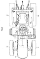
- FIG. 2 is a plan view of the tractor.
- a hood 13 that covers an engine compartment is disposed in a front region of a vehicle body 10 that is supported by front wheels 11 and rear wheels 12, and a driver seat 15 and a ROPS 16 are disposed in a rear region of the vehicle body 10.
- the front wheels 11 are configured as steerable wheels
- the rear wheels 12 are configured as driving wheels.
- the front wheels 11 also function as driving wheels.
- a panel assembly 4 is disposed at the rear end of the hood 13, and a steering wheel 3 is disposed between the panel assembly 4 and the driver seat 15.
- the steering wheel 3 is supported by a steering post 17 that is connected to the panel assembly 4.
- Various operation tools and various meters are attached to the panel assembly 4.
- a display unit 40 for displaying various types of information is disposed on the lower front side of the steering wheel 3.
- the display unit 40 is attached to the panel assembly 4.
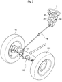
- FIG. 3 schematically shows a steering mechanism 9 for changing the steering angle of the front wheels 11, which are steerable wheels, based on a wheel angle that is a rotation angle of the steering wheel 3 about a wheel rotation shaft 30.
- the steering mechanism 9 includes a power steering unit 90 that is coupled to the left and right front wheels 11.
- a wheel angle detector 91 that detects the wheel angle is provided in the surrounding region of the wheel rotation shaft 30, and a steering angle detector 92 that detects the steering angle of the front wheels 11 is provided in the surrounding region of the power steering unit 90.
- a steering ratio that is a ratio between the wheel angle and the steering angle is not fixed and can be adjusted by an adjusting unit 93.
- the adjusting unit 93 can be constituted by a mechanical transmission unit that performs variable magnification of a change in the rotation angle to generate the steering angle. If the steering mechanism 9 is constituted by steering-by-wire, the adjusting unit 93 is incorporated into an electronic steering control unit that outputs a steering signal for generating the steering angle corresponding to the wheel angle, to the power steering unit 90.
- the tractor is configured to be capable of automatic traveling. Therefore, a steering actuator 94 for automatic steering is provided.
- the steering actuator 94 operates based on a steering control signal that is transmitted in automatic traveling, and steers the front wheels 11 by rotating the wheel rotation shaft 30 in place of the steering wheel 3.
- the steering wheel 3 is constituted by three spokes 31 that extend in the radial direction of the wheel rotation shaft 30, and a ring-shaped member 32 that is connected to end portions of the spokes 31.
- the three spokes 31 are arranged at central angle intervals of 120°, and therefore, substantially fan-shaped openings 33 each having a central angle of 120° are formed between the spokes 31 and the ring-shaped member 32.
- the ring-shaped member 32 does not need to have a complete ring shape, and a portion of the ring-shaped member 32 may be cut out.
- the number of spokes 31 may be two or four or more, and intervals between the spokes 31 may be nonuniform.
- FIG. 4 shows the steering wheel 3 viewed from a driver seated on the driver seat 15.
- the rotation position of the steering wheel 3 is such that one of the openings 33 is located above the display unit 40.
- the opening 33 is within the field of view of the driver seated on the driver seat 15, and the driver can see almost the entire screen of the display unit 40 through the opening 33.
- the wheel angle of the steering wheel 3 at such a rotation position is defined as an appropriate angle.
- FIG. 5 shows an example of the display unit 40.
- the display unit 40 in the present embodiment includes a group of meters 41, a group of LED lamps 42, and a liquid crystal panel 43.
- the group of meters 41 includes a tachometer that is arranged in a left end region and a liquid temperature meter and a fuel meter that are arranged in a right region.
- the group of LED lamps 42 includes a plurality of LED lamps that are arranged in an upper region and a lower region at the center. These LED lamps serve as various warning lamps and confirmation lamps. Note that the entirety or most of the display screen of the display unit 40 may be constituted by the liquid crystal panel.
- the steering mechanism 9 (see FIG. 3 ) is adjusted by the adjusting unit 93 (see FIG. 3 ) such that, in a state where the wheel angle of the steering wheel 3 is the appropriate angle, the steering angle of the front wheels 11 is a neutral steering angle (which is a steering angle for making the vehicle body 10 travel straight and is 0°).
- the driver can have a clear view of information that is displayed in the display unit 40 and is important for traveling of the tractor.
- the tractor includes a function of automatically traveling along a target travel route, and accordingly, needs to calculate a vehicle position. Therefore, a satellite positioning module 8a and an inertial measurement module 8b are provided as a positioning unit 8.
- the satellite positioning module 8a is provided in an upper portion of the ROPS 16 as shown in FIG. 1 , and adopts the principle of a satellite positioning system (GNSS) for detecting the position of the vehicle body 10 by receiving radio waves from satellites.
- GNSS satellite positioning system
- the inertial measurement module 8b includes a gyroscope sensor and an acceleration sensor, and can determine an angular change in the orientation of the vehicle body.
- the inertial measurement module 8b may be disposed at a position different from the satellite positioning module 8a, rather than the same position as the satellite positioning module 8a.
- the inertial measurement module 8b may be disposed at a different position, for example, the same position as the satellite positioning module 8a.
- a control device 5 includes an input output processing unit 50 as an input output interface.
- the input output processing unit 50 is connected to the wheel angle detector 91, the steering angle detector 92, the adjusting unit 93, and the steering actuator 94 described above. Furthermore, the input output processing unit 50 is connected to a group of state detectors 7, a group of manual operation tools 71, and the like.
- the positioning unit 8 described above is connected to the control device 5 via an in-vehicle LAN.
- the display unit 40 displays various types of information based on notification signals from a notification control unit 72.
- the group of state detectors 7 is constituted by various sensors and switches, and includes a travel device state detector 74 and a work device state detector 75.
- the travel device state detector 74 includes sensors that detect the state of travel, such as a vehicle speed sensor, an engine speed sensor, a brake pedal detection sensor, and a parking brake detection sensor (not shown).
- the work device state detector 75 includes a sensor that detects the state of a work device that the tractor is provided with.
- the group of manual operation tools 71 collectively refers to levers, switches, buttons, volume knobs, and the like that are operated by the driver (of which only some are shown in FIG. 2 ), and control instructions are given to the control device 5 as a result of these tools being operated.
- the control device 5 includes a travel control unit 51, a work control unit 52, a route setting unit 53, a steering management unit 54, a vehicle position calculation unit 80, and a travel divergence calculation unit 81, for example.
- the vehicle position calculation unit 80 calculates map coordinates (vehicle position) of the vehicle body 10 based on satellite positioning data that is successively transmitted from the positioning unit 8. At this time, the vehicle position calculation unit 80 converts a position that is directly calculated from the satellite positioning data to a reference point of the vehicle body 10 (e.g., the center of the vehicle body or the center of work). The vehicle position calculation unit 80 also includes a function of calculating a traveling direction that is the orientation of the vehicle body 10 in the front-rear direction by chronologically processing the calculated vehicle position.
- the travel divergence calculation unit 81 calculates travel divergence from the target travel route set for automatic traveling.
- the travel divergence includes a lateral deviation that is a divergence in a lateral direction from the target travel route and a directional deviation that is expressed using an angle formed between the target travel route and the traveling direction.
- the travel control unit 51 transmits a steering control signal to the steering actuator 94 and transmits a transmission control signal and a brake control signal to travel devices such as the transmission and the brake.
- the tractor is capable of automatic traveling and manual traveling, and therefore, the travel control unit 51 includes an automatic travel control unit 511, a manual travel control unit 512, and a travel mode management unit 513.
- An automatic travel mode is set to perform automatic driving and a manual travel mode is set to perform manual driving. These travel modes are managed by the travel mode management unit 513. If the automatic travel mode is set, the automatic travel control unit 511 gives a steering control signal to the steering actuator 94 such that the lateral deviation and the directional deviation calculated by the travel divergence calculation unit 81 are reduced.
- the work control unit 52 controls operations of the work device (not shown) installed in the vehicle body 10.
- the route setting unit 53 calculates a travel route that covers the entire work target area using a program, and sets the travel route as the target travel route according to a determined travel pattern. Note that the travel route may be calculated by another computer or the like, rather than the route setting unit 53 installed in the tractor, and may be transmitted to the route setting unit 53.
- the steering management unit 54 gives, to the adjusting unit 93, an adjustment control signal for making the steering angle detected by the steering angle detector 92 be the neutral steering angle in the state where the wheel angle detected by the wheel angle detector 91 is the appropriate angle.
- the adjusting unit 93 adjusts a relationship between the wheel angle and the steering angle in the steering mechanism 9 (see FIG. 3 ) based on the adjustment control signal.
- the right diagram in FIG. 7 schematically shows a state of the steering mechanism 9 that is adjusted by the adjusting unit 93. Processing for this adjustment is described below.
- 0° G(0°).
- the driver operates an operation tool of the group of manual operation tools 71 that is designated in advance as a trigger switch for adjusting steering.
- the processing for adjusting the steering mechanism 9 is executed.
- the steering mechanism 9 is adjusted by the adjusting unit 93 and the steering management unit 54 (see FIG. 6 ) to change the steering ratio of the steering mechanism 9 such that the steering angle becomes the neutral steering angle when the wheel angle of the steering wheel 3 is the appropriate angle.
- the adjusting unit 93 reads out the stored appropriate angle from the memory, and the steering mechanism 9 is adjusted such that the steering angle becomes the neutral steering angle when the wheel angle is the read appropriate angle.
- This configuration makes it possible to automatically adjust the steering mechanism 9 at a predetermined timing or based on a request from the driver such that the driver can have a clear view of the display unit 40 through the opening 33 when the tractor is traveling in a straight line.
- the appropriate angle of the steering wheel 3 may vary depending on the driver. In order to solve this problem, it is possible to adopt a configuration in which the appropriate angle is determined by each driver.
- an operation tool that is a trigger switch for determining the appropriate angle is designated in advance as an operation tool for setting the appropriate angle, from the group of manual operation tools 71.
- the wheel angle at a point in time at which this operation tool is operated is set as the appropriate angle, and the steering mechanism 9 is adjusted such that the steering angle becomes the neutral steering angle when the steering wheel has this wheel angle.
- the steering angle that makes the steerable wheels travel in a straight line is generated from the wheel angle of the steering wheel 3 at the time when the driver feels that it is easy to see the display unit 40.
- the present invention can be advantageously applied particularly to a work vehicle in which the driver seated on the driver seat views a display unit through the steering wheel.
Landscapes
- Engineering & Computer Science (AREA)
- Chemical & Material Sciences (AREA)
- Combustion & Propulsion (AREA)
- Transportation (AREA)
- Mechanical Engineering (AREA)
- Guiding Agricultural Machines (AREA)
- Steering Controls (AREA)
- Steering Control In Accordance With Driving Conditions (AREA)
Abstract
Description
- The present invention relates to a work vehicle in which a steering wheel for operating a steerable wheel is disposed between a driver seat and a display unit for displaying various types of information.
- Patent Document 1 discloses a work vehicle in which a flat panel display unit is disposed on a steering post and a steering wheel is attached to a steering shaft that extends upward from the steering post. The steering wheel is constituted by a ring and a plurality of spokes that extend in the radial direction of the ring, and an opening is formed by the ring and adjacent spokes. The size of the opening and the position of the flat panel display unit are determined such that a driver seated on the driver seat can see the flat panel display unit through the opening. Therefore, the driver can have a clear view of the screen of the flat panel display unit through the opening of the steering wheel.
- Patent Document 1:
JP 2013-252073A US 2014/062075A1 ) - Work vehicles mainly travel in a straight line, and therefore, in the work vehicle disclosed in Patent Document 1, the attachment position of the steering wheel is determined such that the driver can have a clear view of the screen of the flat panel display unit through the opening of the steering wheel when the rotation position of the steering wheel is that of straight travel. However, an original correct relationship between a wheel angle, which is the rotation angle of the steering wheel, and a steering angle of a steerable wheel cannot be maintained in a steering mechanism for converting the wheel angle to the steering angle, due to change over time or the like. As a result, the wheel angle of straight travel shifts in the clockwise or counterclockwise direction from an original angle, the field of view is interrupted by a spoke, and the driver cannot see the entire screen of the flat panel display unit through the opening of the steering wheel.
- Under the above circumstances, there is demand for a work vehicle that allows the driver to have a clear view of the screen of the flat panel display unit through the opening of the steering wheel regardless of change over time in the steering mechanism.
- A work vehicle according to the present invention includes: a driver seat; a steerable wheel; a display unit configured to display various types of information; a steering wheel disposed on the rear side with respect to the display unit, in front of the driver seat; a wheel angle detector configured to detect a wheel angle that is a rotation angle of the steering wheel about a wheel rotation shaft; a steering mechanism configured to change a steering angle of the steerable wheel based on the wheel angle; and an adjusting unit configured to adjust a relationship between the wheel angle and the steering angle. The steering wheel includes a plurality of spokes and a ring-shaped member that is connected to the spokes, and an opening is formed between the spokes and the ring-shaped member.
- The steering mechanism sets a wheel angle (relationship between the wheel angle and the steering angle) of an initial state in which the display unit can be seen from the driver seat side through the opening of the steering wheel, as the wheel angle of the steering wheel that generates a steering angle (straight travel steering angle) that makes the steerable wheel travel straight. When the initial state changes, a view of the display unit from the driver seat side is interrupted by a spoke when the steering wheel is at the rotation position at which the straight travel steering angle (commonly called a neutral steering angle) is generated. In such a case, according to the configuration of the present invention, it is possible to restore the original initial state by adjusting the relationship between the wheel angle and the steering angle through the adjusting unit.
- In a preferable embodiment of the present invention, the adjusting unit is configured to set, as an appropriate angle, a wheel angle that allows the display unit to be in a field of view from the driver seat side through the opening, and adjust the relationship such that the steering angle becomes the neutral steering angle when the wheel angle is the appropriate angle. In this configuration, the wheel angle that allows the display unit to be seen from the driver seat side through the opening of the steering wheel is set as the appropriate angle, and the steering mechanism is adjusted through the adjusting unit such that the appropriate angle corresponds to the neutral steering angle. As a result, the driver seated on the driver seat can always have a clear view of the screen of the flat panel display unit through the opening of the steering wheel.
- In a preferable embodiment of the present invention, the appropriate angle is stored in advance, the adjusting unit reads out the stored appropriate angle, and adjusts the steering mechanism based on the read appropriate angle such that the steering angle becomes the neutral steering angle. With this configuration, the adjusting unit can automatically adjust the steering mechanism at a predetermined timing or based on a request from the driver such that the display unit is in the field of view of the driver from the driver seat side through the opening when the work vehicle is traveling in a straight line.
- In a preferable embodiment of the present invention, the adjusting unit sets, as the appropriate angle, a rotation angle of the steering wheel at a point in time at which a manual operation tool for setting the appropriate angle is operated, and adjusts the steering mechanism such that the steering angle becomes the neutral steering angle when the wheel angle is the appropriate angle. With this configuration, the steering angle that makes the steerable wheel travel straight is generated from the wheel angle of the steering wheel at the time when the driver feels that it is easy to see the display unit.
-
-
FIG. 1 is a side view of a tractor. -
FIG. 2 is a plan view of the tractor. -
FIG. 3 is a schematic diagram showing a steering mechanism. -
FIG. 4 is a diagram showing a steering wheel and a display unit viewed from the driver seat side. -
FIG. 5 is a front view of the display unit. -
FIG. 6 is a functional block diagram of a control system of the tractor. -
FIG. 7 is a schematic diagram showing steering adjustment of the steering mechanism. - Next, an embodiment of a work vehicle according to the present invention will be described using the drawings.
FIG. 1 is a side view of a tractor that is an example of the work vehicle, andFIG. 2 is a plan view of the tractor. As shown inFIG. 1 , in the tractor, ahood 13 that covers an engine compartment is disposed in a front region of avehicle body 10 that is supported byfront wheels 11 andrear wheels 12, and adriver seat 15 and aROPS 16 are disposed in a rear region of thevehicle body 10. Thefront wheels 11 are configured as steerable wheels, and therear wheels 12 are configured as driving wheels. In a four-wheel drive mode, thefront wheels 11 also function as driving wheels. Apanel assembly 4 is disposed at the rear end of thehood 13, and asteering wheel 3 is disposed between thepanel assembly 4 and thedriver seat 15. Thesteering wheel 3 is supported by asteering post 17 that is connected to thepanel assembly 4. Various operation tools and various meters are attached to thepanel assembly 4. As shown inFIG. 2 , adisplay unit 40 for displaying various types of information is disposed on the lower front side of thesteering wheel 3. Thedisplay unit 40 is attached to thepanel assembly 4. -
FIG. 3 schematically shows asteering mechanism 9 for changing the steering angle of thefront wheels 11, which are steerable wheels, based on a wheel angle that is a rotation angle of thesteering wheel 3 about awheel rotation shaft 30. Thesteering mechanism 9 includes apower steering unit 90 that is coupled to the left and rightfront wheels 11. Awheel angle detector 91 that detects the wheel angle is provided in the surrounding region of thewheel rotation shaft 30, and asteering angle detector 92 that detects the steering angle of thefront wheels 11 is provided in the surrounding region of thepower steering unit 90. In thesteering mechanism 9, a steering ratio that is a ratio between the wheel angle and the steering angle is not fixed and can be adjusted by an adjustingunit 93. The adjustingunit 93 can be constituted by a mechanical transmission unit that performs variable magnification of a change in the rotation angle to generate the steering angle. If thesteering mechanism 9 is constituted by steering-by-wire, the adjustingunit 93 is incorporated into an electronic steering control unit that outputs a steering signal for generating the steering angle corresponding to the wheel angle, to thepower steering unit 90. - The tractor is configured to be capable of automatic traveling. Therefore, a
steering actuator 94 for automatic steering is provided. Thesteering actuator 94 operates based on a steering control signal that is transmitted in automatic traveling, and steers thefront wheels 11 by rotating thewheel rotation shaft 30 in place of thesteering wheel 3. - As shown in
FIGS. 2 and4 , thesteering wheel 3 is constituted by threespokes 31 that extend in the radial direction of thewheel rotation shaft 30, and a ring-shaped member 32 that is connected to end portions of thespokes 31. The threespokes 31 are arranged at central angle intervals of 120°, and therefore, substantially fan-shaped openings 33 each having a central angle of 120° are formed between thespokes 31 and the ring-shaped member 32. Note that the ring-shaped member 32 does not need to have a complete ring shape, and a portion of the ring-shaped member 32 may be cut out. Also, the number ofspokes 31 may be two or four or more, and intervals between thespokes 31 may be nonuniform. -
FIG. 4 shows thesteering wheel 3 viewed from a driver seated on thedriver seat 15. The rotation position of thesteering wheel 3 is such that one of theopenings 33 is located above thedisplay unit 40. When thesteering wheel 3 is at this rotation position, theopening 33 is within the field of view of the driver seated on thedriver seat 15, and the driver can see almost the entire screen of thedisplay unit 40 through theopening 33. Here, the wheel angle of thesteering wheel 3 at such a rotation position is defined as an appropriate angle. -
FIG. 5 shows an example of thedisplay unit 40. Thedisplay unit 40 in the present embodiment includes a group ofmeters 41, a group ofLED lamps 42, and aliquid crystal panel 43. The group ofmeters 41 includes a tachometer that is arranged in a left end region and a liquid temperature meter and a fuel meter that are arranged in a right region. The group ofLED lamps 42 includes a plurality of LED lamps that are arranged in an upper region and a lower region at the center. These LED lamps serve as various warning lamps and confirmation lamps. Note that the entirety or most of the display screen of thedisplay unit 40 may be constituted by the liquid crystal panel. - At the time of shipment from a factory or maintenance, the steering mechanism 9 (see
FIG. 3 ) is adjusted by the adjusting unit 93 (seeFIG. 3 ) such that, in a state where the wheel angle of thesteering wheel 3 is the appropriate angle, the steering angle of thefront wheels 11 is a neutral steering angle (which is a steering angle for making thevehicle body 10 travel straight and is 0°). As a result, when the tractor is traveling straight, the driver can have a clear view of information that is displayed in thedisplay unit 40 and is important for traveling of the tractor. - Next, main functional units of a control system of the tractor will be described using
FIG. 6 . The tractor includes a function of automatically traveling along a target travel route, and accordingly, needs to calculate a vehicle position. Therefore, asatellite positioning module 8a and aninertial measurement module 8b are provided as apositioning unit 8. Thesatellite positioning module 8a is provided in an upper portion of theROPS 16 as shown inFIG. 1 , and adopts the principle of a satellite positioning system (GNSS) for detecting the position of thevehicle body 10 by receiving radio waves from satellites. Theinertial measurement module 8b includes a gyroscope sensor and an acceleration sensor, and can determine an angular change in the orientation of the vehicle body. Theinertial measurement module 8b may be disposed at a position different from thesatellite positioning module 8a, rather than the same position as thesatellite positioning module 8a. Of course, theinertial measurement module 8b may be disposed at a different position, for example, the same position as thesatellite positioning module 8a. - A
control device 5 includes an inputoutput processing unit 50 as an input output interface. The inputoutput processing unit 50 is connected to thewheel angle detector 91, thesteering angle detector 92, the adjustingunit 93, and thesteering actuator 94 described above. Furthermore, the inputoutput processing unit 50 is connected to a group ofstate detectors 7, a group of manual operation tools 71, and the like. Thepositioning unit 8 described above is connected to thecontrol device 5 via an in-vehicle LAN. Thedisplay unit 40 displays various types of information based on notification signals from anotification control unit 72. - The group of
state detectors 7 is constituted by various sensors and switches, and includes a traveldevice state detector 74 and a workdevice state detector 75. The traveldevice state detector 74 includes sensors that detect the state of travel, such as a vehicle speed sensor, an engine speed sensor, a brake pedal detection sensor, and a parking brake detection sensor (not shown). The workdevice state detector 75 includes a sensor that detects the state of a work device that the tractor is provided with. - The group of manual operation tools 71 collectively refers to levers, switches, buttons, volume knobs, and the like that are operated by the driver (of which only some are shown in
FIG. 2 ), and control instructions are given to thecontrol device 5 as a result of these tools being operated. - The
control device 5 includes atravel control unit 51, awork control unit 52, aroute setting unit 53, asteering management unit 54, a vehicleposition calculation unit 80, and a traveldivergence calculation unit 81, for example. - The vehicle
position calculation unit 80 calculates map coordinates (vehicle position) of thevehicle body 10 based on satellite positioning data that is successively transmitted from thepositioning unit 8. At this time, the vehicleposition calculation unit 80 converts a position that is directly calculated from the satellite positioning data to a reference point of the vehicle body 10 (e.g., the center of the vehicle body or the center of work). The vehicleposition calculation unit 80 also includes a function of calculating a traveling direction that is the orientation of thevehicle body 10 in the front-rear direction by chronologically processing the calculated vehicle position. - Based on the vehicle position and the traveling direction calculated by the vehicle
position calculation unit 80, the traveldivergence calculation unit 81 calculates travel divergence from the target travel route set for automatic traveling. The travel divergence includes a lateral deviation that is a divergence in a lateral direction from the target travel route and a directional deviation that is expressed using an angle formed between the target travel route and the traveling direction. - The
travel control unit 51 transmits a steering control signal to thesteering actuator 94 and transmits a transmission control signal and a brake control signal to travel devices such as the transmission and the brake. The tractor is capable of automatic traveling and manual traveling, and therefore, thetravel control unit 51 includes an automatictravel control unit 511, a manualtravel control unit 512, and a travelmode management unit 513. - An automatic travel mode is set to perform automatic driving and a manual travel mode is set to perform manual driving. These travel modes are managed by the travel
mode management unit 513. If the automatic travel mode is set, the automatictravel control unit 511 gives a steering control signal to thesteering actuator 94 such that the lateral deviation and the directional deviation calculated by the traveldivergence calculation unit 81 are reduced. - The
work control unit 52 controls operations of the work device (not shown) installed in thevehicle body 10. - The
route setting unit 53 calculates a travel route that covers the entire work target area using a program, and sets the travel route as the target travel route according to a determined travel pattern. Note that the travel route may be calculated by another computer or the like, rather than theroute setting unit 53 installed in the tractor, and may be transmitted to theroute setting unit 53. - The
steering management unit 54 gives, to the adjustingunit 93, an adjustment control signal for making the steering angle detected by thesteering angle detector 92 be the neutral steering angle in the state where the wheel angle detected by thewheel angle detector 91 is the appropriate angle. The adjustingunit 93 adjusts a relationship between the wheel angle and the steering angle in the steering mechanism 9 (seeFIG. 3 ) based on the adjustment control signal. As a result, when the rotation position of the steering wheel 3 (seeFIG. 3 ) is that of straight travel, almost theentire display unit 40 or at least an important display region of thedisplay unit 40 is inside the opening 33 (seeFIG. 4 ) when viewed from the driver seat side. - Two states of the
steering mechanism 9 before adjustment are schematically shown in the middle portion ofFIG. 7 . In these states, when thesteering wheel 3 is operated by the driver to make the steering angle β be the neutral steering angle so that thevehicle body 10 travels in a straight line, the wheel angle α is not the appropriate angle (=0°) and thesteering wheel 3 deviates from the appropriate angle in the counterclockwise direction. Therefore, aspoke 31 of thesteering wheel 3 overlaps thedisplay unit 40, and the driver seated on the driver seat 15 (seeFIG. 1 ) cannot see a portion of the important display region of thedisplay unit 40 through theopening 33. - In other words, if the wheel angle α is set to the appropriate angle so that the important display region of the
display unit 40 can be clearly seen through theopening 33, the steering angle deviates from the neutral steering angle and the vehicle body cannot travel in a straight line (see the left diagram inFIG. 7 ). In order to solve this problem, steering adjustment is performed by the steering management unit 54 (seeFIG. 6 ) and the adjustingunit 93. - The right diagram in
FIG. 7 schematically shows a state of thesteering mechanism 9 that is adjusted by the adjustingunit 93. Processing for this adjustment is described below. First, when the wheel angle is represented by α, the steering angle is represented by β, and a steering function for determining the steering ratio in thesteering mechanism 9 is represented by G() (corresponding to a function or a table), a steering angle that is generated from a wheel angle can be found as follows: β=G(α). At the time of shipment from a factory or maintenance, basically, 0°=G(0°). If the steering function in thesteering mechanism 9 changes from the original steering function G() to a changed steering function G1 () due to damage or the like of thesteering wheel 3 or thesteering mechanism 9 over time, the steering ratio changes and 0°=G1(0°) does not hold true. That is, when the wheel angle is the appropriate angle (α=0°), the steering angle is not the neutral steering angle (β=0°) but 10°, for example. In other words, when the steering angle is the neutral steering angle (β=0°), the wheel angle is not the appropriate angle (α=0°) but 10°, for example. - The adjusting
unit 93 and thesteering management unit 54 have a function of adjusting thesteering mechanism 9 such that 0°=G1(0°) holds true even in the changed steering function G1( ). That is, thesteering management unit 54 finds θ with which 0°=G1(0°)+θ holds true, and gives adjustment data that corresponds to θ to the adjustingunit 93. The adjustingunit 93 adjusts thesteering mechanism 9 based on the adjustment data. As a result, even in the changed steering function G1( ), the steering angle becomes the neutral steering angle (β=0°) when the wheel angle is the appropriate angle (α=0°). - In a state before the
steering mechanism 9 is adjusted, the driver operates an operation tool of the group of manual operation tools 71 that is designated in advance as a trigger switch for adjusting steering. As a result, the processing for adjusting thesteering mechanism 9 is executed. In this adjustment processing, thesteering mechanism 9 is adjusted by the adjustingunit 93 and the steering management unit 54 (seeFIG. 6 ) to change the steering ratio of thesteering mechanism 9 such that the steering angle becomes the neutral steering angle when the wheel angle of thesteering wheel 3 is the appropriate angle. - Note that, if the appropriate angle is stored in a memory, the adjusting
unit 93 reads out the stored appropriate angle from the memory, and thesteering mechanism 9 is adjusted such that the steering angle becomes the neutral steering angle when the wheel angle is the read appropriate angle. This configuration makes it possible to automatically adjust thesteering mechanism 9 at a predetermined timing or based on a request from the driver such that the driver can have a clear view of thedisplay unit 40 through theopening 33 when the tractor is traveling in a straight line. - The appropriate angle of the
steering wheel 3 may vary depending on the driver. In order to solve this problem, it is possible to adopt a configuration in which the appropriate angle is determined by each driver. In this configuration, an operation tool that is a trigger switch for determining the appropriate angle is designated in advance as an operation tool for setting the appropriate angle, from the group of manual operation tools 71. The wheel angle at a point in time at which this operation tool is operated is set as the appropriate angle, and thesteering mechanism 9 is adjusted such that the steering angle becomes the neutral steering angle when the steering wheel has this wheel angle. Thus, the steering angle that makes the steerable wheels travel in a straight line is generated from the wheel angle of thesteering wheel 3 at the time when the driver feels that it is easy to see thedisplay unit 40. -
- (1) In the above embodiment, an operation that is made on a manual operation tool is used as a trigger for the steering adjustment performed by the adjusting
unit 93 and thesteering management unit 54. Instead of this configuration, a configuration may be adopted in which the steering adjustment is automatically executed if it is determined that thevehicle body 10 is traveling in a straight line, based on a chronological change in the orientation of the vehicle body calculated by the vehicleposition calculation unit 80, and that the steering adjustment is necessary based on a detected steering angle and a detected wheel angle. - (2) In the above embodiment, the adjusting
unit 93 is included in thesteering mechanism 9, and thesteering management unit 54 is included in the control system. Instead of this configuration, a configuration is also possible in which thesteering management unit 54 is also included in thesteering mechanism 9. - (3) In the above embodiment, the tractor that is capable of automatic traveling is described, but the present invention is also effective when applied to a work vehicle that is only capable of manual traveling.
- The present invention can be advantageously applied particularly to a work vehicle in which the driver seated on the driver seat views a display unit through the steering wheel.
-
- 10: Vehicle body
- 11: Front wheel
- 12: Rear wheel
- 3: Steering wheel
- 30: Wheel rotation shaft
- 31: Spoke
- 32: Ring-shaped member
- 33: Opening
- 40: Display unit
- 5: Control device
- 50: Input output processing unit
- 54: Steering management unit
- 71: Group of manual operation tools
- 9: Steering mechanism
- 90: Power steering unit
- 91: Wheel angle detector
- 92: Steering angle detector
- 93: Adjusting unit
- 94: Steering actuator
Claims (4)
- A work vehicle comprising:a driver seat;a steerable wheel;a display unit configured to display various types of information;a steering wheel disposed on the rear side with respect to the display unit, in front of the driver seat;a wheel angle detector configured to detect a wheel angle that is a rotation angle of the steering wheel about a wheel rotation shaft;a steering mechanism configured to change a steering angle of the steerable wheel based on the wheel angle; andan adjusting unit configured to adjust a relationship between the wheel angle and the steering angle, whereinthe steering wheel includes a plurality of spokes and a ring-shaped member that is connected to the spokes, and an opening is formed between the spokes and the ring-shaped member.
- The work vehicle according to claim 1, wherein
the adjusting unit sets, as an appropriate angle, a wheel angle that allows the display unit to be in a field of view from the driver seat side through the opening, and adjusts the relationship such that the steering angle becomes a neutral steering angle when the wheel angle is the appropriate angle. - The work vehicle according to claim 2, wherein
the appropriate angle is stored in advance, the adjusting unit reads out the stored appropriate angle, and adjusts the steering mechanism based on the read appropriate angle such that the steering angle becomes the neutral steering angle. - The work vehicle according to claim 2, wherein
the adjusting unit sets, as the appropriate angle, a rotation angle of the steering wheel at a point in time at which a manual operation tool for setting the appropriate angle is operated, and adjusts the steering mechanism such that the steering angle becomes the neutral steering angle when the wheel angle is the appropriate angle.
Applications Claiming Priority (2)
| Application Number | Priority Date | Filing Date | Title |
|---|---|---|---|
| JP2018238894A JP2020100236A (en) | 2018-12-20 | 2018-12-20 | Work vehicle |
| PCT/JP2019/048371 WO2020129760A1 (en) | 2018-12-20 | 2019-12-11 | Work vehicle |
Publications (3)
| Publication Number | Publication Date |
|---|---|
| EP3901001A1 true EP3901001A1 (en) | 2021-10-27 |
| EP3901001A4 EP3901001A4 (en) | 2022-10-12 |
| EP3901001B1 EP3901001B1 (en) | 2024-10-30 |
Family
ID=71102157
Family Applications (1)
| Application Number | Title | Priority Date | Filing Date |
|---|---|---|---|
| EP19900209.8A Active EP3901001B1 (en) | 2018-12-20 | 2019-12-11 | Work vehicle |
Country Status (4)
| Country | Link |
|---|---|
| US (1) | US11945498B2 (en) |
| EP (1) | EP3901001B1 (en) |
| JP (1) | JP2020100236A (en) |
| WO (1) | WO2020129760A1 (en) |
Families Citing this family (2)
| Publication number | Priority date | Publication date | Assignee | Title |
|---|---|---|---|---|
| KR102805478B1 (en) * | 2020-07-15 | 2025-05-09 | 현대자동차주식회사 | Integrated memory system for driving position and method for controlling the same |
| CA3209767A1 (en) | 2022-09-28 | 2024-03-28 | Toyota Material Handling, Inc. | Synchronized steering control systems for forklifts |
Family Cites Families (14)
| Publication number | Priority date | Publication date | Assignee | Title |
|---|---|---|---|---|
| JP2002225724A (en) * | 2001-01-30 | 2002-08-14 | Mitsubishi Motors Corp | Operating device for in-vehicle equipment |
| US7295907B2 (en) * | 2005-06-14 | 2007-11-13 | Trw Automotive U.S. Llc | Recovery of calibrated center steering position after loss of battery power |
| JP4528213B2 (en) * | 2005-06-23 | 2010-08-18 | 本田技研工業株式会社 | Vehicle steering system |
| AU2006281802A1 (en) * | 2005-08-18 | 2007-02-22 | Sauer-Danfoss Aps | A method of calibrating and steering a vehicle provided with a positioning system |
| JP2007203761A (en) * | 2006-01-30 | 2007-08-16 | Jtekt Corp | Vehicle steering system |
| JP4788618B2 (en) | 2007-01-29 | 2011-10-05 | 株式会社ジェイテクト | Vehicle steering system |
| JP2010173410A (en) * | 2009-01-28 | 2010-08-12 | Tokai Rika Co Ltd | Function display device |
| JP5704869B2 (en) | 2010-09-14 | 2015-04-22 | 株式会社クボタ | Paddy field machine |
| JP5576224B2 (en) * | 2010-09-15 | 2014-08-20 | 株式会社クボタ | Paddy field machine |
| JP2013252073A (en) | 2012-06-05 | 2013-12-19 | Kubota Corp | Working vehicle equipped with ground working unit |
| DE102014226615B4 (en) * | 2014-12-19 | 2017-11-09 | Volkswagen Aktiengesellschaft | A motor vehicle steering system and method for adjusting the steering wheel position in a motor vehicle steering system |
| FR3048087B1 (en) * | 2016-02-18 | 2018-02-16 | Continental Automotive France | OPTICAL DETECTION OF THE POSITION OF THE STEERING WHEEL |
| US11059511B2 (en) * | 2017-02-28 | 2021-07-13 | Ford Motor Company | Optimizing alignment of steering column and steering wheel during vehicle production |
| US10315691B2 (en) | 2017-03-30 | 2019-06-11 | Ford Global Technologies, Llc | Methods and apparatus to correct clear vision errors in a vehicle steering system |
-
2018
- 2018-12-20 JP JP2018238894A patent/JP2020100236A/en active Pending
-
2019
- 2019-12-11 EP EP19900209.8A patent/EP3901001B1/en active Active
- 2019-12-11 WO PCT/JP2019/048371 patent/WO2020129760A1/en not_active Ceased
- 2019-12-11 US US17/295,890 patent/US11945498B2/en active Active
Also Published As
| Publication number | Publication date |
|---|---|
| EP3901001B1 (en) | 2024-10-30 |
| US20220126916A1 (en) | 2022-04-28 |
| JP2020100236A (en) | 2020-07-02 |
| US11945498B2 (en) | 2024-04-02 |
| EP3901001A4 (en) | 2022-10-12 |
| WO2020129760A1 (en) | 2020-06-25 |
Similar Documents
| Publication | Publication Date | Title |
|---|---|---|
| JP7277520B2 (en) | work vehicle | |
| US7679495B2 (en) | Displaying unit and method for displaying a steering-wheel angle, to be modified, of a motor vehicle | |
| KR102696042B1 (en) | work vehicle | |
| JP7779966B2 (en) | Tractor | |
| EP2608186B1 (en) | Trailer backing path prediction using GPS and camera images | |
| JP4847178B2 (en) | Vehicle driving support device | |
| EP3466232B1 (en) | Work vehicle and time-based management system applicable to the work vehicle | |
| JP4288482B2 (en) | Vehicle display device using three-dimensional images | |
| WO2005080135A1 (en) | Onboard display device, vehicle, display method, image display program, and recording medium | |
| US11912350B2 (en) | Work vehicle | |
| EP3901001B1 (en) | Work vehicle | |
| JP2024040453A (en) | work vehicle | |
| JP3496365B2 (en) | Vehicle navigation system | |
| US11889779B2 (en) | Work vehicle | |
| JP2007518995A (en) | Vehicle guidance method along predetermined track, and vehicle and system for performing collision experiment | |
| JP2005071114A (en) | Vehicle guidance control device | |
| JPH02283571A (en) | Vehicle auxiliary steering device | |
| US20170300218A1 (en) | Vehicle display control device | |
| US10409287B2 (en) | Vehicle guide display and path navigation method | |
| JP2020000025A (en) | Work vehicle | |
| JP2010175524A (en) | Display apparatus for vehicle | |
| WO2020090864A1 (en) | Steering wheel angle control device | |
| JP2020000024A (en) | Work vehicle | |
| JPH08254431A (en) | Vehicle corner detection device | |
| JP2019203846A (en) | Speedometer control system and speedometer control program |
Legal Events
| Date | Code | Title | Description |
|---|---|---|---|
| STAA | Information on the status of an ep patent application or granted ep patent |
Free format text: STATUS: THE INTERNATIONAL PUBLICATION HAS BEEN MADE |
|
| PUAI | Public reference made under article 153(3) epc to a published international application that has entered the european phase |
Free format text: ORIGINAL CODE: 0009012 |
|
| STAA | Information on the status of an ep patent application or granted ep patent |
Free format text: STATUS: REQUEST FOR EXAMINATION WAS MADE |
|
| 17P | Request for examination filed |
Effective date: 20210527 |
|
| AK | Designated contracting states |
Kind code of ref document: A1 Designated state(s): AL AT BE BG CH CY CZ DE DK EE ES FI FR GB GR HR HU IE IS IT LI LT LU LV MC MK MT NL NO PL PT RO RS SE SI SK SM TR |
|
| DAV | Request for validation of the european patent (deleted) | ||
| DAX | Request for extension of the european patent (deleted) | ||
| A4 | Supplementary search report drawn up and despatched |
Effective date: 20220909 |
|
| RIC1 | Information provided on ipc code assigned before grant |
Ipc: B62D 1/10 20060101ALI20220905BHEP Ipc: B62D 1/16 20060101ALI20220905BHEP Ipc: B62D 5/04 20060101ALI20220905BHEP Ipc: B62D 6/00 20060101ALI20220905BHEP Ipc: B62D 1/20 20060101ALI20220905BHEP Ipc: B62D 1/04 20060101AFI20220905BHEP |
|
| GRAP | Despatch of communication of intention to grant a patent |
Free format text: ORIGINAL CODE: EPIDOSNIGR1 |
|
| STAA | Information on the status of an ep patent application or granted ep patent |
Free format text: STATUS: GRANT OF PATENT IS INTENDED |
|
| RIC1 | Information provided on ipc code assigned before grant |
Ipc: B62D 1/10 20060101ALI20240607BHEP Ipc: B62D 1/16 20060101ALI20240607BHEP Ipc: B62D 5/04 20060101ALI20240607BHEP Ipc: B62D 6/00 20060101ALI20240607BHEP Ipc: B62D 1/20 20060101ALI20240607BHEP Ipc: B62D 1/04 20060101AFI20240607BHEP |
|
| INTG | Intention to grant announced |
Effective date: 20240716 |
|
| GRAS | Grant fee paid |
Free format text: ORIGINAL CODE: EPIDOSNIGR3 |
|
| GRAA | (expected) grant |
Free format text: ORIGINAL CODE: 0009210 |
|
| STAA | Information on the status of an ep patent application or granted ep patent |
Free format text: STATUS: THE PATENT HAS BEEN GRANTED |
|
| AK | Designated contracting states |
Kind code of ref document: B1 Designated state(s): AL AT BE BG CH CY CZ DE DK EE ES FI FR GB GR HR HU IE IS IT LI LT LU LV MC MK MT NL NO PL PT RO RS SE SI SK SM TR |
|
| REG | Reference to a national code |
Ref country code: GB Ref legal event code: FG4D |
|
| REG | Reference to a national code |
Ref country code: CH Ref legal event code: EP |
|
| REG | Reference to a national code |
Ref country code: IE Ref legal event code: FG4D |
|
| REG | Reference to a national code |
Ref country code: DE Ref legal event code: R096 Ref document number: 602019061320 Country of ref document: DE |
|
| REG | Reference to a national code |
Ref country code: LT Ref legal event code: MG9D |
|
| REG | Reference to a national code |
Ref country code: NL Ref legal event code: MP Effective date: 20241030 |
|
| PG25 | Lapsed in a contracting state [announced via postgrant information from national office to epo] |
Ref country code: PT Free format text: LAPSE BECAUSE OF FAILURE TO SUBMIT A TRANSLATION OF THE DESCRIPTION OR TO PAY THE FEE WITHIN THE PRESCRIBED TIME-LIMIT Effective date: 20250228 Ref country code: HR Free format text: LAPSE BECAUSE OF FAILURE TO SUBMIT A TRANSLATION OF THE DESCRIPTION OR TO PAY THE FEE WITHIN THE PRESCRIBED TIME-LIMIT Effective date: 20241030 Ref country code: IS Free format text: LAPSE BECAUSE OF FAILURE TO SUBMIT A TRANSLATION OF THE DESCRIPTION OR TO PAY THE FEE WITHIN THE PRESCRIBED TIME-LIMIT Effective date: 20250228 |
|
| PG25 | Lapsed in a contracting state [announced via postgrant information from national office to epo] |
Ref country code: FI Free format text: LAPSE BECAUSE OF FAILURE TO SUBMIT A TRANSLATION OF THE DESCRIPTION OR TO PAY THE FEE WITHIN THE PRESCRIBED TIME-LIMIT Effective date: 20241030 Ref country code: NL Free format text: LAPSE BECAUSE OF FAILURE TO SUBMIT A TRANSLATION OF THE DESCRIPTION OR TO PAY THE FEE WITHIN THE PRESCRIBED TIME-LIMIT Effective date: 20241030 |
|
| REG | Reference to a national code |
Ref country code: AT Ref legal event code: MK05 Ref document number: 1736647 Country of ref document: AT Kind code of ref document: T Effective date: 20241030 |
|
| PG25 | Lapsed in a contracting state [announced via postgrant information from national office to epo] |
Ref country code: BG Free format text: LAPSE BECAUSE OF FAILURE TO SUBMIT A TRANSLATION OF THE DESCRIPTION OR TO PAY THE FEE WITHIN THE PRESCRIBED TIME-LIMIT Effective date: 20241030 |
|
| PG25 | Lapsed in a contracting state [announced via postgrant information from national office to epo] |
Ref country code: ES Free format text: LAPSE BECAUSE OF FAILURE TO SUBMIT A TRANSLATION OF THE DESCRIPTION OR TO PAY THE FEE WITHIN THE PRESCRIBED TIME-LIMIT Effective date: 20241030 |
|
| PG25 | Lapsed in a contracting state [announced via postgrant information from national office to epo] |
Ref country code: NO Free format text: LAPSE BECAUSE OF FAILURE TO SUBMIT A TRANSLATION OF THE DESCRIPTION OR TO PAY THE FEE WITHIN THE PRESCRIBED TIME-LIMIT Effective date: 20250130 |
|
| PG25 | Lapsed in a contracting state [announced via postgrant information from national office to epo] |
Ref country code: AT Free format text: LAPSE BECAUSE OF FAILURE TO SUBMIT A TRANSLATION OF THE DESCRIPTION OR TO PAY THE FEE WITHIN THE PRESCRIBED TIME-LIMIT Effective date: 20241030 Ref country code: LV Free format text: LAPSE BECAUSE OF FAILURE TO SUBMIT A TRANSLATION OF THE DESCRIPTION OR TO PAY THE FEE WITHIN THE PRESCRIBED TIME-LIMIT Effective date: 20241030 Ref country code: GR Free format text: LAPSE BECAUSE OF FAILURE TO SUBMIT A TRANSLATION OF THE DESCRIPTION OR TO PAY THE FEE WITHIN THE PRESCRIBED TIME-LIMIT Effective date: 20250131 |
|
| PG25 | Lapsed in a contracting state [announced via postgrant information from national office to epo] |
Ref country code: PL Free format text: LAPSE BECAUSE OF FAILURE TO SUBMIT A TRANSLATION OF THE DESCRIPTION OR TO PAY THE FEE WITHIN THE PRESCRIBED TIME-LIMIT Effective date: 20241030 |
|
| PG25 | Lapsed in a contracting state [announced via postgrant information from national office to epo] |
Ref country code: RS Free format text: LAPSE BECAUSE OF FAILURE TO SUBMIT A TRANSLATION OF THE DESCRIPTION OR TO PAY THE FEE WITHIN THE PRESCRIBED TIME-LIMIT Effective date: 20250130 |
|
| PG25 | Lapsed in a contracting state [announced via postgrant information from national office to epo] |
Ref country code: SM Free format text: LAPSE BECAUSE OF FAILURE TO SUBMIT A TRANSLATION OF THE DESCRIPTION OR TO PAY THE FEE WITHIN THE PRESCRIBED TIME-LIMIT Effective date: 20241030 |
|
| PG25 | Lapsed in a contracting state [announced via postgrant information from national office to epo] |
Ref country code: MC Free format text: LAPSE BECAUSE OF FAILURE TO SUBMIT A TRANSLATION OF THE DESCRIPTION OR TO PAY THE FEE WITHIN THE PRESCRIBED TIME-LIMIT Effective date: 20241030 |
|
| PG25 | Lapsed in a contracting state [announced via postgrant information from national office to epo] |
Ref country code: DK Free format text: LAPSE BECAUSE OF FAILURE TO SUBMIT A TRANSLATION OF THE DESCRIPTION OR TO PAY THE FEE WITHIN THE PRESCRIBED TIME-LIMIT Effective date: 20241030 |
|
| PG25 | Lapsed in a contracting state [announced via postgrant information from national office to epo] |
Ref country code: EE Free format text: LAPSE BECAUSE OF FAILURE TO SUBMIT A TRANSLATION OF THE DESCRIPTION OR TO PAY THE FEE WITHIN THE PRESCRIBED TIME-LIMIT Effective date: 20241030 |
|
| PG25 | Lapsed in a contracting state [announced via postgrant information from national office to epo] |
Ref country code: RO Free format text: LAPSE BECAUSE OF FAILURE TO SUBMIT A TRANSLATION OF THE DESCRIPTION OR TO PAY THE FEE WITHIN THE PRESCRIBED TIME-LIMIT Effective date: 20241030 |
|
| PG25 | Lapsed in a contracting state [announced via postgrant information from national office to epo] |
Ref country code: SK Free format text: LAPSE BECAUSE OF FAILURE TO SUBMIT A TRANSLATION OF THE DESCRIPTION OR TO PAY THE FEE WITHIN THE PRESCRIBED TIME-LIMIT Effective date: 20241030 |
|
| PG25 | Lapsed in a contracting state [announced via postgrant information from national office to epo] |
Ref country code: CZ Free format text: LAPSE BECAUSE OF FAILURE TO SUBMIT A TRANSLATION OF THE DESCRIPTION OR TO PAY THE FEE WITHIN THE PRESCRIBED TIME-LIMIT Effective date: 20241030 |
|
| PG25 | Lapsed in a contracting state [announced via postgrant information from national office to epo] |
Ref country code: IT Free format text: LAPSE BECAUSE OF FAILURE TO SUBMIT A TRANSLATION OF THE DESCRIPTION OR TO PAY THE FEE WITHIN THE PRESCRIBED TIME-LIMIT Effective date: 20241030 |
|
| REG | Reference to a national code |
Ref country code: CH Ref legal event code: PL Ref country code: DE Ref legal event code: R097 Ref document number: 602019061320 Country of ref document: DE |
|
| PG25 | Lapsed in a contracting state [announced via postgrant information from national office to epo] |
Ref country code: LU Free format text: LAPSE BECAUSE OF NON-PAYMENT OF DUE FEES Effective date: 20241211 |
|
| PLBE | No opposition filed within time limit |
Free format text: ORIGINAL CODE: 0009261 |
|
| STAA | Information on the status of an ep patent application or granted ep patent |
Free format text: STATUS: NO OPPOSITION FILED WITHIN TIME LIMIT |
|
| PG25 | Lapsed in a contracting state [announced via postgrant information from national office to epo] |
Ref country code: SE Free format text: LAPSE BECAUSE OF FAILURE TO SUBMIT A TRANSLATION OF THE DESCRIPTION OR TO PAY THE FEE WITHIN THE PRESCRIBED TIME-LIMIT Effective date: 20241030 |
|
| GBPC | Gb: european patent ceased through non-payment of renewal fee |
Effective date: 20250130 |
|
| 26N | No opposition filed |
Effective date: 20250731 |
|
| REG | Reference to a national code |
Ref country code: BE Ref legal event code: MM Effective date: 20241231 |
|
| PG25 | Lapsed in a contracting state [announced via postgrant information from national office to epo] |
Ref country code: BE Free format text: LAPSE BECAUSE OF NON-PAYMENT OF DUE FEES Effective date: 20241231 Ref country code: GB Free format text: LAPSE BECAUSE OF NON-PAYMENT OF DUE FEES Effective date: 20250130 |
|
| PG25 | Lapsed in a contracting state [announced via postgrant information from national office to epo] |
Ref country code: CH Free format text: LAPSE BECAUSE OF NON-PAYMENT OF DUE FEES Effective date: 20241231 |
|
| PG25 | Lapsed in a contracting state [announced via postgrant information from national office to epo] |
Ref country code: IE Free format text: LAPSE BECAUSE OF NON-PAYMENT OF DUE FEES Effective date: 20241211 |
|
| PGFP | Annual fee paid to national office [announced via postgrant information from national office to epo] |
Ref country code: DE Payment date: 20251028 Year of fee payment: 7 |
|
| PGFP | Annual fee paid to national office [announced via postgrant information from national office to epo] |
Ref country code: FR Payment date: 20251110 Year of fee payment: 7 |