EP3900958A1 - Pneumatic tire - Google Patents
Pneumatic tire Download PDFInfo
- Publication number
- EP3900958A1 EP3900958A1 EP19900699.0A EP19900699A EP3900958A1 EP 3900958 A1 EP3900958 A1 EP 3900958A1 EP 19900699 A EP19900699 A EP 19900699A EP 3900958 A1 EP3900958 A1 EP 3900958A1
- Authority
- EP
- European Patent Office
- Prior art keywords
- region
- side wall
- tire
- wall portion
- small regions
- Prior art date
- Legal status (The legal status is an assumption and is not a legal conclusion. Google has not performed a legal analysis and makes no representation as to the accuracy of the status listed.)
- Granted
Links
Images



Classifications
-
- B—PERFORMING OPERATIONS; TRANSPORTING
- B60—VEHICLES IN GENERAL
- B60C—VEHICLE TYRES; TYRE INFLATION; TYRE CHANGING; CONNECTING VALVES TO INFLATABLE ELASTIC BODIES IN GENERAL; DEVICES OR ARRANGEMENTS RELATED TO TYRES
- B60C13/00—Tyre sidewalls; Protecting, decorating, marking, or the like, thereof
- B60C13/001—Decorating, marking or the like
Definitions
- the present invention relates to pneumatic tires.
- Patent Document 1 A technique for making unevenness present on an outer surface of a side wall portion inconspicuous.
- Patent Document 1 A plurality of circumferential pattern element arrays in which a plurality of pattern elements having the same contour shape are continuously provided in a tire circumferential direction and a plurality of radial pattern element arrays in which a plurality of pattern elements are continuously provided in a tire radial direction are formed on the side wall portion in Patent Document 1.
- Patent Document 1 Japanese Patent Application Publication No. 2013-71572
- the present invention provides a pneumatic tire that improves the appearance of the side wall portion even when the gauge thickness of the side wall portion is thinned down.
- a pneumatic tire (pneumatic tire 1) according to the present invention comprising: a tread portion (tread portion 2) is in contact with a road surface; and a side wall portion (side wall portion 3) is continuous to the tread portion and positioned inside a tire radial direction of the tread portion.
- a large region (large region 10) comprising a plurality of small regions (small regions 11, 12 and 13) having different arithmetic average roughness outside in a tire width direction is formed on outer surface of the side wall portion.
- a plurality of large regions 10 are formed along a tire circumferential direction and the tire radial direction. In a boundary line of adjacent large region 10, small regions having different arithmetic average roughness come into contact with each other.
- the appearance of the side wall portion is improved.
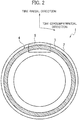
- Fig. 1 is a partial sectional view of a pneumatic tire 1 according to the present embodiment. Specifically, Fig. 1 is the sectional view of the pneumatic tire 1 along a tire width direction and a tire radial direction. Fig. 1 shows only one side with respect to a tire equator line CL. Fig. 2 is a side view of the pneumatic tire 1 according to the present embodiment.
- the pneumatic tire 1 includes a tread portion 2, a side wall portion 3, a carcass 6, and a bead portion 7.
- the tread portion 2 is in contact with a road surface (unillustrated).
- a pattern (unillustrated) corresponding to usage environment of the pneumatic tire 1 or the kind of a vehicle to be mounted is formed.
- the side wall portion 3 is continuous to the tread portion 2 and positioned inside the tire radial direction of the tread portion 2.
- the side wall portion 3 is a region from the tire width direction outside end of the tread portion 2 to the upper end of the bead portion 7.
- the carcass 6 forms a skeleton of the pneumatic tire 1.
- the carcass 6 has a radial structure having carcass cords (unillustrated) radially arranged along the tire radial direction.
- the carcass 6 is not limited to the radial structure, and may be a bias structure in which the carcass cords are arranged so as to cross each other in the tire radial direction.
- the bead portion 7 is continuous to the side wall portion 3 and positioned inside the tire radial direction of the side wall portion 3.
- the bead portion 7 is annular, and the carcass 6 is folded back from the inside in the tire width direction to the outside in the tire width direction through the bead portion 7.
- a decorative region 4 (first decorative region) is formed on outer surface of the side wall portion 3.
- the decorative region 4 is annularly formed along the tire circumferential direction. Although the details of the decorative region 4 will be described later, a large number of large regions 10 are formed in the decorative region 4.
- a place where the decorative region 4 is formed includes tire maximum width.
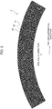
- Fig. 3 is an enlarged view of the region 5 shown in Fig. 2 .
- the decorative region 4 comprises a plurality of large regions 10.
- the plurality of large regions 10 are formed along the tire circumferential direction and the tire radial direction.
- a shape of the large region 10 is quadrangular in the top view of the large region 10.
- the shape of the large region 10 is not limited to quadrangular.
- the large region 10 includes a plurality of small regions (small regions 11, 12 and 13).
- shapes of the small regions 11, 12 and 13 are all triangular.
- the shapes of the small regions 11, 12 and 13 is not limited to triangular.
- the small regions 11, 12 and 13 are processed by laser, for example.
- an arithmetic average roughness outside in the tire width direction is different from each other as shown in Fig. 5 .
- the arithmetic average roughness of the small region 11 outside in the tire width direction is 1.2 ⁇ m to 1.4 ⁇ m.
- the arithmetic average roughness of the small region 12 outside in the tire width direction is 1.5 ⁇ m to 1.8 ⁇ m.
- the arithmetic average roughness of the small region 13 outside in the tire width direction is 1.9 ⁇ m to 4.5 ⁇ m.
- the small regions 11, 12 and 13 form one triangular pyramid. Two of triangular pyramids are combined to form a large region 10. In other words, the large region 10 is formed by combining two small regions 11, 12 and 13.
- the small regions having different arithmetic average roughness come into contact with each other at a boundary line of the adjacent large region 10.
- Reference signs 20 to 24 in Fig. 6 show the boundary lines between the large region 10 in the center of Fig. 6 and the large region 10 adjacent to this large region 10.
- the small region 11 and the small region 13 are come into contact with each other.
- the boundary line 21 the small region 11 and the small region 12 are come into contact with each other.
- the boundary line 22 the small region 11 and the small region 13 are come into contact with each other.
- the boundary line 23 the small region 11 and the small region 12 are come into contact with each other. In this way, in the adjacent large region 10, the small regions having different arithmetic average roughness come into contact with each other.
- the large region 10 comprising the plurality of small regions 11, 12 and 13 having different arithmetic average roughness outside in the tire width direction is formed on the outer surface of the side wall portion 3.
- the plurality of large regions 10 are formed along the tire circumferential direction and the tire radial direction. In the boundary lines of adjacent large region 10, small regions having different arithmetic average roughness come into contact with each other.
- the contrast caused by the difference in the arithmetic average roughness of the small regions 11, 12 and 13 produces a three-dimensional feeling with unevenness.
- the gauge thickness of the side wall portion 3 is thinned down, the appearance of the side wall portion 3 is improved.
- the shape of the large region 10 is quadrangular in the top view of the large region 10.
- the shapes of the small regions 11, 12 and 13 in the top view of the large region 10 are all triangular, and the small regions 11, 12 and 13 form one triangular pyramid. Two of triangular pyramids are combined to form a large region 10.
- the triangular pyramid shape enhances the unevenness, so that an user can obtain the three-dimensional feeling.
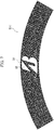
- a mark region 50 (second decorative region) different from the decorative region 4 may be formed on the outer surface of the side wall portion 3.
- a mark 30 is formed in the mark region 50.
- the mark 30 is, for example, a mark.
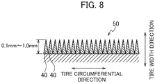
- the mark 30 comprises a plurality of protrusions 40.
- the height of the protrusion 40 is 0.1mm to 1.0mm, for example. Combination of the mark 30 and the large region 10 further enhances the three-dimensional feeling and the appearance of the side wall portion 3 is improved.
- the length of the mark 30 in the tire radial direction is 20mm or more.
- the shape of the large region 10 is not limited to quadrangular shown in Fig. 4 .
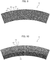
- the shape shown in Figs. 9 to 10 may be adopted as the shape of the large region 10.
- the arithmetic average roughness of the small regions 11, 12 and 13 is different from each other.
- the value of the arithmetic average roughness is the same as the value described above.
- the shapes of Figs. 9 to 10 the same effects as those described above can be obtained.
Landscapes
- Engineering & Computer Science (AREA)
- Mechanical Engineering (AREA)
- Tires In General (AREA)
Abstract
Description
- The present invention relates to pneumatic tires.
- There has been known a technique for making unevenness present on an outer surface of a side wall portion inconspicuous (Patent Document 1). A plurality of circumferential pattern element arrays in which a plurality of pattern elements having the same contour shape are continuously provided in a tire circumferential direction and a plurality of radial pattern element arrays in which a plurality of pattern elements are continuously provided in a tire radial direction are formed on the side wall portion in
Patent Document 1. - [Patent Document 1]
Japanese Patent Application Publication No. 2013-71572 - In recent years, as demands for environmental protection increase, further weight reduction of tires is required. As an example method of reducing the weight of the tires, it is known to thin down the gauge thickness of the side wall portion. However when the gauge thickness of the side wall portion is thinned down, the unevenness is not formed deeply and it is difficult to improve an appearance of the side wall portion.
- In view of the foregoing problem, the present invention provides a pneumatic tire that improves the appearance of the side wall portion even when the gauge thickness of the side wall portion is thinned down.
- A pneumatic tire (pneumatic tire 1) according to the present invention comprising: a tread portion (tread portion 2) is in contact with a road surface; and a side wall portion (side wall portion 3) is continuous to the tread portion and positioned inside a tire radial direction of the tread portion. A large region (large region 10) comprising a plurality of small regions (
small regions large regions 10 are formed along a tire circumferential direction and the tire radial direction. In a boundary line of adjacentlarge region 10, small regions having different arithmetic average roughness come into contact with each other. - According to the present invention, even when the gauge thickness of the side wall portion is thinned down, the appearance of the side wall portion is improved.
-
- [
Fig. 1] Fig. 1 is a cross-sectional view of a pneumatic tire along in a tire width direction and a tire radial direction. - [
Fig. 2] Fig. 2 is a side view of the pneumatic tire. - [
Fig. 3] Fig. 3 is a partially enlarged view ofFig. 2 . - [
Fig. 4] Fig. 4 is a diagram for explaining a large region according to the embodiment of the present invention. - [
Fig. 5] Fig. 5 is a diagram for explaining an arithmetic average roughness of a small region according to the embodiment of the present invention. - [
Fig. 6] Fig. 6 is a diagram for explaining a large region according to the embodiment of the present invention. - [
Fig. 7] Fig. 7 is a diagram for explaining a mark according to another embodiment of the present invention. - [
Fig. 8] Fig. 8 is a cross-sectional view from A-A direction ofFig. 7 . - [
Fig. 9] Fig. 9 is a diagram for explaining another embodiment of the present invention. - [
Fig. 10] Fig. 10 is a diagram for explaining another embodiment of the present invention. - Hereinafter, an embodiment of the present invention will be described with reference to the drawings. In the illustration of the drawings, the same constituents are denoted by the same reference signs, and description thereof is omitted.
-
Fig. 1 is a partial sectional view of apneumatic tire 1 according to the present embodiment. Specifically,Fig. 1 is the sectional view of thepneumatic tire 1 along a tire width direction and a tire radial direction.Fig. 1 shows only one side with respect to a tire equator line CL.Fig. 2 is a side view of thepneumatic tire 1 according to the present embodiment. - As shown in
Figs. 1 to 2 , thepneumatic tire 1 includes atread portion 2, aside wall portion 3, acarcass 6, and abead portion 7. - The
tread portion 2 is in contact with a road surface (unillustrated). In thetread portion 2, a pattern (unillustrated) corresponding to usage environment of thepneumatic tire 1 or the kind of a vehicle to be mounted is formed. - The
side wall portion 3 is continuous to thetread portion 2 and positioned inside the tire radial direction of thetread portion 2. Theside wall portion 3 is a region from the tire width direction outside end of thetread portion 2 to the upper end of thebead portion 7. - The
carcass 6 forms a skeleton of thepneumatic tire 1. Thecarcass 6 has a radial structure having carcass cords (unillustrated) radially arranged along the tire radial direction. However, thecarcass 6 is not limited to the radial structure, and may be a bias structure in which the carcass cords are arranged so as to cross each other in the tire radial direction. - The
bead portion 7 is continuous to theside wall portion 3 and positioned inside the tire radial direction of theside wall portion 3. Thebead portion 7 is annular, and thecarcass 6 is folded back from the inside in the tire width direction to the outside in the tire width direction through thebead portion 7. - As shown in
Fig. 2 , a decorative region 4 (first decorative region) is formed on outer surface of theside wall portion 3. Thedecorative region 4 is annularly formed along the tire circumferential direction. Although the details of thedecorative region 4 will be described later, a large number oflarge regions 10 are formed in thedecorative region 4. A place where thedecorative region 4 is formed includes tire maximum width. - Next, with reference to
Fig. 3 a partial area (adashed area 5 shown inFig. 2 ) of thedecorative region 4 shown inFig. 2 will be described.Fig. 3 is an enlarged view of theregion 5 shown inFig. 2 . As shown inFig. 3 , thedecorative region 4 comprises a plurality oflarge regions 10. The plurality oflarge regions 10 are formed along the tire circumferential direction and the tire radial direction. - Next, with reference to
Figs. 4 to 6 , thelarge region 10 will be described in detail. As shown inFig. 4 , a shape of thelarge region 10 is quadrangular in the top view of thelarge region 10. However, as will be described later, the shape of thelarge region 10 is not limited to quadrangular. As shown inFig. 4 , thelarge region 10 includes a plurality of small regions (small regions large region 10, shapes of thesmall regions small regions small regions - In the
small regions Fig. 5 . The arithmetic average roughness of thesmall region 11 outside in the tire width direction is 1.2µm to 1.4µm. The arithmetic average roughness of thesmall region 12 outside in the tire width direction is 1.5µm to 1.8µm. The arithmetic average roughness of thesmall region 13 outside in the tire width direction is 1.9µm to 4.5µm. - In the example shown in
Fig. 4 , thesmall regions large region 10. In other words, thelarge region 10 is formed by combining twosmall regions - Further, as shown in
Fig. 6 , the small regions having different arithmetic average roughness come into contact with each other at a boundary line of the adjacentlarge region 10. Reference signs 20 to 24 inFig. 6 show the boundary lines between thelarge region 10 in the center ofFig. 6 and thelarge region 10 adjacent to thislarge region 10. In theboundary line 20, thesmall region 11 and thesmall region 13 are come into contact with each other. In the boundary line 21, thesmall region 11 and thesmall region 12 are come into contact with each other. In theboundary line 22, thesmall region 11 and thesmall region 13 are come into contact with each other. In theboundary line 23, thesmall region 11 and thesmall region 12 are come into contact with each other. In this way, in the adjacentlarge region 10, the small regions having different arithmetic average roughness come into contact with each other. - As described above, the
large region 10 comprising the plurality ofsmall regions side wall portion 3. The plurality oflarge regions 10 are formed along the tire circumferential direction and the tire radial direction. In the boundary lines of adjacentlarge region 10, small regions having different arithmetic average roughness come into contact with each other. The contrast caused by the difference in the arithmetic average roughness of thesmall regions side wall portion 3 is thinned down, the appearance of theside wall portion 3 is improved. - As shown in
Fig. 4 , the shape of thelarge region 10 is quadrangular in the top view of thelarge region 10. The shapes of thesmall regions large region 10 are all triangular, and thesmall regions large region 10. The triangular pyramid shape enhances the unevenness, so that an user can obtain the three-dimensional feeling. - While the present invention has been described above by reference to the embodiment, it should be understood that the present invention is not intended to be limited to the descriptions and the drawings composing part of this disclosure. Various alternative embodiments, examples, and technical applications will be apparent to those skilled in the art according to this disclosure.
- For example, as shown in
Fig. 7 , a mark region 50 (second decorative region) different from thedecorative region 4 may be formed on the outer surface of theside wall portion 3. As shown inFig. 7 , amark 30 is formed in themark region 50. Themark 30 is, for example, a mark. Themark 30 comprises a plurality ofprotrusions 40. As shown inFig. 8 , the height of theprotrusion 40 is 0.1mm to 1.0mm, for example. Combination of themark 30 and thelarge region 10 further enhances the three-dimensional feeling and the appearance of theside wall portion 3 is improved. As an example, the length of themark 30 in the tire radial direction is 20mm or more. - The shape of the
large region 10 is not limited to quadrangular shown inFig. 4 . For example, the shape shown inFigs. 9 to 10 may be adopted as the shape of thelarge region 10. Also inFigs. 9 to 10 , the arithmetic average roughness of thesmall regions Figs. 9 to 10 , the same effects as those described above can be obtained. - This application is based upon and claims the benefit of priority from
Japanese Patent Application No. 2018-236003, filed on December 18, 2018 -
- 1
- pneumatic tire
- 2
- tread portion
- 3
- side wall portion
- 4
- decorative region
- 6
- carcass
- 7
- bead portion
- 10
- large region
- 11-13
- small region
- 20-23
- boundary line
- 30
- mark
- 40
- protrusion
- 50
- mark region
Claims (4)
- A pneumatic tire comprising:a tread portion is in contact with a road surface; anda side wall portion is continuous to the tread portion and positioned inside a tire radial direction of the tread portion,whereina large region comprising a plurality of small regions having different arithmetic average roughness outside in a tire width direction is formed on outer surface of the side wall portion,a plurality of large regions are formed along a tire circumferential direction and the tire radial direction, andin a boundary line of adjacent large region, small regions having different arithmetic average roughness come into contact with each other.
- The pneumatic tire according to claim 1, whereinthe large region comprising three small regions, andthe arithmetic average roughness of the three small regions is 1.2µm to 1.4µm, 1.5µm to 1.8µm, and 1.9µm to 4.5µm, respectively.
- The pneumatic tire according to claim 2, wherein
shapes of the three small regions in top view of the large region are all triangular. - The pneumatic tire according to any one of claims 1 to 3, whereina first decorative region comprising a plurality of the large regions and a second decorative region different from the first decorative region are formed on outer surface of the side wall portion,a plurality of protrusions are formed in the second decorative region, andheight of the protrusion is 0.1mm to 1.0mm.
Applications Claiming Priority (2)
| Application Number | Priority Date | Filing Date | Title |
|---|---|---|---|
| JP2018236003A JP7099945B2 (en) | 2018-12-18 | 2018-12-18 | Pneumatic tires |
| PCT/JP2019/046889 WO2020129579A1 (en) | 2018-12-18 | 2019-11-29 | Pneumatic tire |
Publications (3)
| Publication Number | Publication Date |
|---|---|
| EP3900958A1 true EP3900958A1 (en) | 2021-10-27 |
| EP3900958A4 EP3900958A4 (en) | 2022-08-17 |
| EP3900958B1 EP3900958B1 (en) | 2024-05-22 |
Family
ID=71100294
Family Applications (1)
| Application Number | Title | Priority Date | Filing Date |
|---|---|---|---|
| EP19900699.0A Active EP3900958B1 (en) | 2018-12-18 | 2019-11-29 | Pneumatic tire |
Country Status (5)
| Country | Link |
|---|---|
| US (1) | US11964516B2 (en) |
| EP (1) | EP3900958B1 (en) |
| JP (1) | JP7099945B2 (en) |
| CN (1) | CN113195263B (en) |
| WO (1) | WO2020129579A1 (en) |
Families Citing this family (7)
| Publication number | Priority date | Publication date | Assignee | Title |
|---|---|---|---|---|
| KR102530621B1 (en) * | 2021-01-14 | 2023-05-08 | 한국타이어앤테크놀로지 주식회사 | Tire |
| JP2022142662A (en) * | 2021-03-16 | 2022-09-30 | 株式会社ブリヂストン | tire |
| JP7519975B2 (en) * | 2021-10-19 | 2024-07-22 | Toyo Tire株式会社 | Pneumatic tires |
| JP7816998B2 (en) * | 2022-02-03 | 2026-02-18 | Toyo Tire株式会社 | pneumatic tires |
| JP7783071B2 (en) * | 2022-02-03 | 2025-12-09 | Toyo Tire株式会社 | pneumatic tires |
| CN116968479A (en) * | 2022-04-23 | 2023-10-31 | 山东东岳科技发展有限公司 | Tire surface array microstructure and tire thereof |
| KR102833469B1 (en) * | 2024-12-06 | 2025-07-11 | 금호타이어 주식회사 | Protuded knurling unit and tire including the same |
Family Cites Families (23)
| Publication number | Priority date | Publication date | Assignee | Title |
|---|---|---|---|---|
| US4198774A (en) * | 1977-11-18 | 1980-04-22 | The Goodyear Tire & Rubber Company | Indicia for rubber articles |
| JP3007825B2 (en) * | 1995-09-28 | 2000-02-07 | 住友ゴム工業株式会社 | Pneumatic tire |
| US5645661A (en) * | 1995-11-09 | 1997-07-08 | The Goodyear Tire & Rubber Company | Tire sidewall |
| US6253815B1 (en) | 1998-08-14 | 2001-07-03 | Michelin Recherche Et Techniques S.A. | Design pattern for a tire |
| JP5230229B2 (en) * | 2007-04-05 | 2013-07-10 | 東洋ゴム工業株式会社 | Pneumatic tire |
| FR2950566B1 (en) * | 2009-09-28 | 2011-08-26 | Michelin Soc Tech | HIGH CONTRAST PNEUMATIC PATTERN AND METHOD OF OBTAINING |
| JP5358404B2 (en) * | 2009-11-19 | 2013-12-04 | 株式会社ブリヂストン | Pneumatic tire |
| WO2011062241A1 (en) * | 2009-11-19 | 2011-05-26 | 株式会社ブリヂストン | Tire |
| JP6068139B2 (en) * | 2010-03-26 | 2017-01-25 | 株式会社ブリヂストン | Tire and method for manufacturing tire vulcanizing mold |
| JP5618058B2 (en) * | 2010-06-10 | 2014-11-05 | 横浜ゴム株式会社 | Pneumatic tire |
| US20130228261A1 (en) | 2010-08-31 | 2013-09-05 | Bridgestone Corporation | Pneumatic tire |
| JP2012101754A (en) * | 2010-11-12 | 2012-05-31 | Yokohama Rubber Co Ltd:The | Pneumatic tire and vulcanizing mold of the same |
| JP5494518B2 (en) * | 2011-02-07 | 2014-05-14 | 横浜ゴム株式会社 | Pneumatic tire |
| JP5287961B2 (en) * | 2011-09-27 | 2013-09-11 | 横浜ゴム株式会社 | Pneumatic tire |
| JP5652376B2 (en) * | 2011-11-15 | 2015-01-14 | 横浜ゴム株式会社 | Pneumatic tire |
| JP5747826B2 (en) * | 2012-01-11 | 2015-07-15 | 横浜ゴム株式会社 | Pneumatic tire |
| JP6209870B2 (en) * | 2013-06-14 | 2017-10-11 | 横浜ゴム株式会社 | Pneumatic tire |
| JP6392076B2 (en) * | 2014-10-27 | 2018-09-19 | 株式会社ブリヂストン | Pneumatic tire |
| FR3034358B1 (en) * | 2015-03-30 | 2018-03-23 | Compagnie Generale Des Etablissements Michelin | PNEUMATIC TIRE TREAD WITH TEXTURES |
| JP6489945B2 (en) | 2015-06-04 | 2019-03-27 | 株式会社ブリヂストン | tire |
| DE102015225419A1 (en) | 2015-12-16 | 2017-06-22 | Continental Reifen Deutschland Gmbh | vehicle tires |
| JP6617040B2 (en) * | 2016-01-25 | 2019-12-04 | 株式会社ブリヂストン | tire |
| DE102016218487A1 (en) | 2016-09-27 | 2018-03-29 | Continental Reifen Deutschland Gmbh | vehicle tires |
-
2018
- 2018-12-18 JP JP2018236003A patent/JP7099945B2/en active Active
-
2019
- 2019-11-29 EP EP19900699.0A patent/EP3900958B1/en active Active
- 2019-11-29 WO PCT/JP2019/046889 patent/WO2020129579A1/en not_active Ceased
- 2019-11-29 CN CN201980084154.4A patent/CN113195263B/en active Active
- 2019-11-29 US US17/415,232 patent/US11964516B2/en active Active
Also Published As
| Publication number | Publication date |
|---|---|
| EP3900958B1 (en) | 2024-05-22 |
| CN113195263A (en) | 2021-07-30 |
| WO2020129579A1 (en) | 2020-06-25 |
| CN113195263B (en) | 2023-03-24 |
| US20220063348A1 (en) | 2022-03-03 |
| US11964516B2 (en) | 2024-04-23 |
| EP3900958A4 (en) | 2022-08-17 |
| JP7099945B2 (en) | 2022-07-12 |
| JP2020097300A (en) | 2020-06-25 |
Similar Documents
| Publication | Publication Date | Title |
|---|---|---|
| EP3900958A1 (en) | Pneumatic tire | |
| EP3115230B1 (en) | Tire | |
| EP2781376B1 (en) | Pneumatic tire | |
| CN103144501B (en) | Pneumatic belt tire | |
| US8006732B2 (en) | Pneumatic tire with sidewall decorative band | |
| JPH11321243A (en) | Pneumatic tire with annular decorative body consisting of semispherical projections | |
| US10625541B2 (en) | Pneumatic tire | |
| JP2013010401A (en) | Pneumatic tire | |
| KR950031554A (en) | Tire tread | |
| US10029518B2 (en) | Pneumatic tire | |
| US20200324580A1 (en) | Pneumatic Tire | |
| JPH11291722A (en) | Pneumatic tire provided with annular ornamental unit formed by many ridges | |
| JP3946850B2 (en) | Pneumatic tire with an annular decorative body consisting of many ridges | |
| JP2009067355A (en) | tire | |
| JPH11291721A (en) | Pneumatic tire provided with annular ornamental unit formed by many ridges | |
| JP2023032836A (en) | pneumatic tire | |
| JP2003146025A (en) | tire | |
| JP4315515B2 (en) | Pneumatic tire | |
| JP2008273301A (en) | Pneumatic tire | |
| JP2000118208A (en) | Pneumatic tire provided with many rectangular decorative bodies | |
| JP5823877B2 (en) | tire | |
| JPH11321242A (en) | Pneumatic tire with annular decorative body consisting of a number of semispherical projections | |
| JPH06106917A (en) | Pneumatic tire for motorcycle | |
| JP2020100165A (en) | tire | |
| CN222495983U (en) | Pneumatic tire |
Legal Events
| Date | Code | Title | Description |
|---|---|---|---|
| STAA | Information on the status of an ep patent application or granted ep patent |
Free format text: STATUS: THE INTERNATIONAL PUBLICATION HAS BEEN MADE |
|
| PUAI | Public reference made under article 153(3) epc to a published international application that has entered the european phase |
Free format text: ORIGINAL CODE: 0009012 |
|
| STAA | Information on the status of an ep patent application or granted ep patent |
Free format text: STATUS: REQUEST FOR EXAMINATION WAS MADE |
|
| 17P | Request for examination filed |
Effective date: 20210716 |
|
| AK | Designated contracting states |
Kind code of ref document: A1 Designated state(s): AL AT BE BG CH CY CZ DE DK EE ES FI FR GB GR HR HU IE IS IT LI LT LU LV MC MK MT NL NO PL PT RO RS SE SI SK SM TR |
|
| DAV | Request for validation of the european patent (deleted) | ||
| DAX | Request for extension of the european patent (deleted) | ||
| A4 | Supplementary search report drawn up and despatched |
Effective date: 20220718 |
|
| RIC1 | Information provided on ipc code assigned before grant |
Ipc: B60C 13/00 20060101AFI20220712BHEP |
|
| GRAP | Despatch of communication of intention to grant a patent |
Free format text: ORIGINAL CODE: EPIDOSNIGR1 |
|
| STAA | Information on the status of an ep patent application or granted ep patent |
Free format text: STATUS: GRANT OF PATENT IS INTENDED |
|
| INTG | Intention to grant announced |
Effective date: 20240109 |
|
| P01 | Opt-out of the competence of the unified patent court (upc) registered |
Effective date: 20240229 |
|
| GRAS | Grant fee paid |
Free format text: ORIGINAL CODE: EPIDOSNIGR3 |
|
| GRAA | (expected) grant |
Free format text: ORIGINAL CODE: 0009210 |
|
| STAA | Information on the status of an ep patent application or granted ep patent |
Free format text: STATUS: THE PATENT HAS BEEN GRANTED |
|
| AK | Designated contracting states |
Kind code of ref document: B1 Designated state(s): AL AT BE BG CH CY CZ DE DK EE ES FI FR GB GR HR HU IE IS IT LI LT LU LV MC MK MT NL NO PL PT RO RS SE SI SK SM TR |
|
| REG | Reference to a national code |
Ref country code: GB Ref legal event code: FG4D |
|
| REG | Reference to a national code |
Ref country code: CH Ref legal event code: EP |
|
| REG | Reference to a national code |
Ref country code: DE Ref legal event code: R096 Ref document number: 602019052770 Country of ref document: DE |
|
| REG | Reference to a national code |
Ref country code: IE Ref legal event code: FG4D |
|
| REG | Reference to a national code |
Ref country code: LT Ref legal event code: MG9D |
|
| REG | Reference to a national code |
Ref country code: NL Ref legal event code: MP Effective date: 20240522 |
|
| PG25 | Lapsed in a contracting state [announced via postgrant information from national office to epo] |
Ref country code: IS Free format text: LAPSE BECAUSE OF FAILURE TO SUBMIT A TRANSLATION OF THE DESCRIPTION OR TO PAY THE FEE WITHIN THE PRESCRIBED TIME-LIMIT Effective date: 20240922 |
|
| PG25 | Lapsed in a contracting state [announced via postgrant information from national office to epo] |
Ref country code: BG Free format text: LAPSE BECAUSE OF FAILURE TO SUBMIT A TRANSLATION OF THE DESCRIPTION OR TO PAY THE FEE WITHIN THE PRESCRIBED TIME-LIMIT Effective date: 20240522 |
|
| PG25 | Lapsed in a contracting state [announced via postgrant information from national office to epo] |
Ref country code: HR Free format text: LAPSE BECAUSE OF FAILURE TO SUBMIT A TRANSLATION OF THE DESCRIPTION OR TO PAY THE FEE WITHIN THE PRESCRIBED TIME-LIMIT Effective date: 20240522 Ref country code: FI Free format text: LAPSE BECAUSE OF FAILURE TO SUBMIT A TRANSLATION OF THE DESCRIPTION OR TO PAY THE FEE WITHIN THE PRESCRIBED TIME-LIMIT Effective date: 20240522 |
|
| PG25 | Lapsed in a contracting state [announced via postgrant information from national office to epo] |
Ref country code: GR Free format text: LAPSE BECAUSE OF FAILURE TO SUBMIT A TRANSLATION OF THE DESCRIPTION OR TO PAY THE FEE WITHIN THE PRESCRIBED TIME-LIMIT Effective date: 20240823 |
|
| PG25 | Lapsed in a contracting state [announced via postgrant information from national office to epo] |
Ref country code: PT Free format text: LAPSE BECAUSE OF FAILURE TO SUBMIT A TRANSLATION OF THE DESCRIPTION OR TO PAY THE FEE WITHIN THE PRESCRIBED TIME-LIMIT Effective date: 20240923 |
|
| REG | Reference to a national code |
Ref country code: AT Ref legal event code: MK05 Ref document number: 1688485 Country of ref document: AT Kind code of ref document: T Effective date: 20240522 |
|
| PG25 | Lapsed in a contracting state [announced via postgrant information from national office to epo] |
Ref country code: NL Free format text: LAPSE BECAUSE OF FAILURE TO SUBMIT A TRANSLATION OF THE DESCRIPTION OR TO PAY THE FEE WITHIN THE PRESCRIBED TIME-LIMIT Effective date: 20240522 |
|
| PG25 | Lapsed in a contracting state [announced via postgrant information from national office to epo] |
Ref country code: ES Free format text: LAPSE BECAUSE OF FAILURE TO SUBMIT A TRANSLATION OF THE DESCRIPTION OR TO PAY THE FEE WITHIN THE PRESCRIBED TIME-LIMIT Effective date: 20240522 |
|
| PG25 | Lapsed in a contracting state [announced via postgrant information from national office to epo] |
Ref country code: AT Free format text: LAPSE BECAUSE OF FAILURE TO SUBMIT A TRANSLATION OF THE DESCRIPTION OR TO PAY THE FEE WITHIN THE PRESCRIBED TIME-LIMIT Effective date: 20240522 |
|
| PG25 | Lapsed in a contracting state [announced via postgrant information from national office to epo] |
Ref country code: PL Free format text: LAPSE BECAUSE OF FAILURE TO SUBMIT A TRANSLATION OF THE DESCRIPTION OR TO PAY THE FEE WITHIN THE PRESCRIBED TIME-LIMIT Effective date: 20240522 |
|
| PG25 | Lapsed in a contracting state [announced via postgrant information from national office to epo] |
Ref country code: LV Free format text: LAPSE BECAUSE OF FAILURE TO SUBMIT A TRANSLATION OF THE DESCRIPTION OR TO PAY THE FEE WITHIN THE PRESCRIBED TIME-LIMIT Effective date: 20240522 |
|
| PG25 | Lapsed in a contracting state [announced via postgrant information from national office to epo] |
Ref country code: PT Free format text: LAPSE BECAUSE OF FAILURE TO SUBMIT A TRANSLATION OF THE DESCRIPTION OR TO PAY THE FEE WITHIN THE PRESCRIBED TIME-LIMIT Effective date: 20240923 Ref country code: PL Free format text: LAPSE BECAUSE OF FAILURE TO SUBMIT A TRANSLATION OF THE DESCRIPTION OR TO PAY THE FEE WITHIN THE PRESCRIBED TIME-LIMIT Effective date: 20240522 Ref country code: NO Free format text: LAPSE BECAUSE OF FAILURE TO SUBMIT A TRANSLATION OF THE DESCRIPTION OR TO PAY THE FEE WITHIN THE PRESCRIBED TIME-LIMIT Effective date: 20240822 Ref country code: NL Free format text: LAPSE BECAUSE OF FAILURE TO SUBMIT A TRANSLATION OF THE DESCRIPTION OR TO PAY THE FEE WITHIN THE PRESCRIBED TIME-LIMIT Effective date: 20240522 Ref country code: LV Free format text: LAPSE BECAUSE OF FAILURE TO SUBMIT A TRANSLATION OF THE DESCRIPTION OR TO PAY THE FEE WITHIN THE PRESCRIBED TIME-LIMIT Effective date: 20240522 Ref country code: IS Free format text: LAPSE BECAUSE OF FAILURE TO SUBMIT A TRANSLATION OF THE DESCRIPTION OR TO PAY THE FEE WITHIN THE PRESCRIBED TIME-LIMIT Effective date: 20240922 Ref country code: HR Free format text: LAPSE BECAUSE OF FAILURE TO SUBMIT A TRANSLATION OF THE DESCRIPTION OR TO PAY THE FEE WITHIN THE PRESCRIBED TIME-LIMIT Effective date: 20240522 Ref country code: GR Free format text: LAPSE BECAUSE OF FAILURE TO SUBMIT A TRANSLATION OF THE DESCRIPTION OR TO PAY THE FEE WITHIN THE PRESCRIBED TIME-LIMIT Effective date: 20240823 Ref country code: FI Free format text: LAPSE BECAUSE OF FAILURE TO SUBMIT A TRANSLATION OF THE DESCRIPTION OR TO PAY THE FEE WITHIN THE PRESCRIBED TIME-LIMIT Effective date: 20240522 Ref country code: ES Free format text: LAPSE BECAUSE OF FAILURE TO SUBMIT A TRANSLATION OF THE DESCRIPTION OR TO PAY THE FEE WITHIN THE PRESCRIBED TIME-LIMIT Effective date: 20240522 Ref country code: BG Free format text: LAPSE BECAUSE OF FAILURE TO SUBMIT A TRANSLATION OF THE DESCRIPTION OR TO PAY THE FEE WITHIN THE PRESCRIBED TIME-LIMIT Effective date: 20240522 Ref country code: AT Free format text: LAPSE BECAUSE OF FAILURE TO SUBMIT A TRANSLATION OF THE DESCRIPTION OR TO PAY THE FEE WITHIN THE PRESCRIBED TIME-LIMIT Effective date: 20240522 Ref country code: RS Free format text: LAPSE BECAUSE OF FAILURE TO SUBMIT A TRANSLATION OF THE DESCRIPTION OR TO PAY THE FEE WITHIN THE PRESCRIBED TIME-LIMIT Effective date: 20240822 |
|
| PG25 | Lapsed in a contracting state [announced via postgrant information from national office to epo] |
Ref country code: DK Free format text: LAPSE BECAUSE OF FAILURE TO SUBMIT A TRANSLATION OF THE DESCRIPTION OR TO PAY THE FEE WITHIN THE PRESCRIBED TIME-LIMIT Effective date: 20240522 |
|
| PG25 | Lapsed in a contracting state [announced via postgrant information from national office to epo] |
Ref country code: EE Free format text: LAPSE BECAUSE OF FAILURE TO SUBMIT A TRANSLATION OF THE DESCRIPTION OR TO PAY THE FEE WITHIN THE PRESCRIBED TIME-LIMIT Effective date: 20240522 |
|
| PG25 | Lapsed in a contracting state [announced via postgrant information from national office to epo] |
Ref country code: CZ Free format text: LAPSE BECAUSE OF FAILURE TO SUBMIT A TRANSLATION OF THE DESCRIPTION OR TO PAY THE FEE WITHIN THE PRESCRIBED TIME-LIMIT Effective date: 20240522 |
|
| PG25 | Lapsed in a contracting state [announced via postgrant information from national office to epo] |
Ref country code: SK Free format text: LAPSE BECAUSE OF FAILURE TO SUBMIT A TRANSLATION OF THE DESCRIPTION OR TO PAY THE FEE WITHIN THE PRESCRIBED TIME-LIMIT Effective date: 20240522 Ref country code: RO Free format text: LAPSE BECAUSE OF FAILURE TO SUBMIT A TRANSLATION OF THE DESCRIPTION OR TO PAY THE FEE WITHIN THE PRESCRIBED TIME-LIMIT Effective date: 20240522 |
|
| PG25 | Lapsed in a contracting state [announced via postgrant information from national office to epo] |
Ref country code: SM Free format text: LAPSE BECAUSE OF FAILURE TO SUBMIT A TRANSLATION OF THE DESCRIPTION OR TO PAY THE FEE WITHIN THE PRESCRIBED TIME-LIMIT Effective date: 20240522 |
|
| PG25 | Lapsed in a contracting state [announced via postgrant information from national office to epo] |
Ref country code: SM Free format text: LAPSE BECAUSE OF FAILURE TO SUBMIT A TRANSLATION OF THE DESCRIPTION OR TO PAY THE FEE WITHIN THE PRESCRIBED TIME-LIMIT Effective date: 20240522 Ref country code: SK Free format text: LAPSE BECAUSE OF FAILURE TO SUBMIT A TRANSLATION OF THE DESCRIPTION OR TO PAY THE FEE WITHIN THE PRESCRIBED TIME-LIMIT Effective date: 20240522 Ref country code: RO Free format text: LAPSE BECAUSE OF FAILURE TO SUBMIT A TRANSLATION OF THE DESCRIPTION OR TO PAY THE FEE WITHIN THE PRESCRIBED TIME-LIMIT Effective date: 20240522 Ref country code: EE Free format text: LAPSE BECAUSE OF FAILURE TO SUBMIT A TRANSLATION OF THE DESCRIPTION OR TO PAY THE FEE WITHIN THE PRESCRIBED TIME-LIMIT Effective date: 20240522 Ref country code: DK Free format text: LAPSE BECAUSE OF FAILURE TO SUBMIT A TRANSLATION OF THE DESCRIPTION OR TO PAY THE FEE WITHIN THE PRESCRIBED TIME-LIMIT Effective date: 20240522 Ref country code: CZ Free format text: LAPSE BECAUSE OF FAILURE TO SUBMIT A TRANSLATION OF THE DESCRIPTION OR TO PAY THE FEE WITHIN THE PRESCRIBED TIME-LIMIT Effective date: 20240522 |
|
| PG25 | Lapsed in a contracting state [announced via postgrant information from national office to epo] |
Ref country code: IT Free format text: LAPSE BECAUSE OF FAILURE TO SUBMIT A TRANSLATION OF THE DESCRIPTION OR TO PAY THE FEE WITHIN THE PRESCRIBED TIME-LIMIT Effective date: 20240522 |
|
| REG | Reference to a national code |
Ref country code: DE Ref legal event code: R097 Ref document number: 602019052770 Country of ref document: DE |
|
| PLBE | No opposition filed within time limit |
Free format text: ORIGINAL CODE: 0009261 |
|
| STAA | Information on the status of an ep patent application or granted ep patent |
Free format text: STATUS: NO OPPOSITION FILED WITHIN TIME LIMIT |
|
| PG25 | Lapsed in a contracting state [announced via postgrant information from national office to epo] |
Ref country code: SI Free format text: LAPSE BECAUSE OF FAILURE TO SUBMIT A TRANSLATION OF THE DESCRIPTION OR TO PAY THE FEE WITHIN THE PRESCRIBED TIME-LIMIT Effective date: 20240522 |
|
| 26N | No opposition filed |
Effective date: 20250225 |
|
| REG | Reference to a national code |
Ref country code: CH Ref legal event code: PL |
|
| PG25 | Lapsed in a contracting state [announced via postgrant information from national office to epo] |
Ref country code: MC Free format text: LAPSE BECAUSE OF FAILURE TO SUBMIT A TRANSLATION OF THE DESCRIPTION OR TO PAY THE FEE WITHIN THE PRESCRIBED TIME-LIMIT Effective date: 20240522 |
|
| PG25 | Lapsed in a contracting state [announced via postgrant information from national office to epo] |
Ref country code: LU Free format text: LAPSE BECAUSE OF NON-PAYMENT OF DUE FEES Effective date: 20241129 |
|
| REG | Reference to a national code |
Ref country code: CH Ref legal event code: PL |
|
| GBPC | Gb: european patent ceased through non-payment of renewal fee |
Effective date: 20241129 |
|
| PG25 | Lapsed in a contracting state [announced via postgrant information from national office to epo] |
Ref country code: CH Free format text: LAPSE BECAUSE OF NON-PAYMENT OF DUE FEES Effective date: 20241130 |
|
| REG | Reference to a national code |
Ref country code: BE Ref legal event code: MM Effective date: 20241130 |
|
| PG25 | Lapsed in a contracting state [announced via postgrant information from national office to epo] |
Ref country code: SE Free format text: LAPSE BECAUSE OF FAILURE TO SUBMIT A TRANSLATION OF THE DESCRIPTION OR TO PAY THE FEE WITHIN THE PRESCRIBED TIME-LIMIT Effective date: 20240522 |
|
| PG25 | Lapsed in a contracting state [announced via postgrant information from national office to epo] |
Ref country code: BE Free format text: LAPSE BECAUSE OF NON-PAYMENT OF DUE FEES Effective date: 20241130 Ref country code: GB Free format text: LAPSE BECAUSE OF NON-PAYMENT OF DUE FEES Effective date: 20241129 |
|
| PG25 | Lapsed in a contracting state [announced via postgrant information from national office to epo] |
Ref country code: IE Free format text: LAPSE BECAUSE OF NON-PAYMENT OF DUE FEES Effective date: 20241129 |
|
| PGFP | Annual fee paid to national office [announced via postgrant information from national office to epo] |
Ref country code: DE Payment date: 20251119 Year of fee payment: 7 |
|
| PGFP | Annual fee paid to national office [announced via postgrant information from national office to epo] |
Ref country code: FR Payment date: 20251126 Year of fee payment: 7 |
|
| PG25 | Lapsed in a contracting state [announced via postgrant information from national office to epo] |
Ref country code: HU Free format text: LAPSE BECAUSE OF FAILURE TO SUBMIT A TRANSLATION OF THE DESCRIPTION OR TO PAY THE FEE WITHIN THE PRESCRIBED TIME-LIMIT; INVALID AB INITIO Effective date: 20191129 |
|
| PG25 | Lapsed in a contracting state [announced via postgrant information from national office to epo] |
Ref country code: CY Free format text: LAPSE BECAUSE OF FAILURE TO SUBMIT A TRANSLATION OF THE DESCRIPTION OR TO PAY THE FEE WITHIN THE PRESCRIBED TIME-LIMIT; INVALID AB INITIO Effective date: 20191129 |