EP3900946A1 - Jante de bicyclette en matériau composite avec des ailes à structure renforcée - Google Patents
Jante de bicyclette en matériau composite avec des ailes à structure renforcée Download PDFInfo
- Publication number
- EP3900946A1 EP3900946A1 EP21168458.4A EP21168458A EP3900946A1 EP 3900946 A1 EP3900946 A1 EP 3900946A1 EP 21168458 A EP21168458 A EP 21168458A EP 3900946 A1 EP3900946 A1 EP 3900946A1
- Authority
- EP
- European Patent Office
- Prior art keywords
- layered structure
- rim
- wrapping
- wings
- layered
- Prior art date
- Legal status (The legal status is an assumption and is not a legal conclusion. Google has not performed a legal analysis and makes no representation as to the accuracy of the status listed.)
- Pending
Links
- 239000002131 composite material Substances 0.000 title claims abstract description 22
- 230000002093 peripheral effect Effects 0.000 claims abstract description 36
- 239000000463 material Substances 0.000 claims abstract description 31
- 238000000034 method Methods 0.000 claims description 12
- 230000001154 acute effect Effects 0.000 claims description 8
- 230000015572 biosynthetic process Effects 0.000 claims description 4
- 230000032798 delamination Effects 0.000 abstract description 3
- 230000009172 bursting Effects 0.000 abstract description 2
- 230000002787 reinforcement Effects 0.000 abstract description 2
- 230000000472 traumatic effect Effects 0.000 abstract description 2
- 239000011159 matrix material Substances 0.000 description 11
- 229920001187 thermosetting polymer Polymers 0.000 description 7
- 239000010410 layer Substances 0.000 description 4
- 238000005498 polishing Methods 0.000 description 4
- 238000000605 extraction Methods 0.000 description 3
- 239000011347 resin Substances 0.000 description 3
- 229920005989 resin Polymers 0.000 description 3
- 229920001169 thermoplastic Polymers 0.000 description 3
- 239000004416 thermosoftening plastic Substances 0.000 description 3
- ZOXJGFHDIHLPTG-UHFFFAOYSA-N Boron Chemical compound [B] ZOXJGFHDIHLPTG-UHFFFAOYSA-N 0.000 description 2
- OKTJSMMVPCPJKN-UHFFFAOYSA-N Carbon Chemical compound [C] OKTJSMMVPCPJKN-UHFFFAOYSA-N 0.000 description 2
- 229920003235 aromatic polyamide Polymers 0.000 description 2
- 229910052796 boron Inorganic materials 0.000 description 2
- 229910052799 carbon Inorganic materials 0.000 description 2
- 239000000919 ceramic Substances 0.000 description 2
- 238000010276 construction Methods 0.000 description 2
- 238000004132 cross linking Methods 0.000 description 2
- 239000003365 glass fiber Substances 0.000 description 2
- 230000003993 interaction Effects 0.000 description 2
- 238000003801 milling Methods 0.000 description 2
- 238000005728 strengthening Methods 0.000 description 2
- 230000008719 thickening Effects 0.000 description 2
- 230000001419 dependent effect Effects 0.000 description 1
- 230000010339 dilation Effects 0.000 description 1
- 230000000694 effects Effects 0.000 description 1
- 239000004744 fabric Substances 0.000 description 1
- 238000010438 heat treatment Methods 0.000 description 1
- 238000001746 injection moulding Methods 0.000 description 1
- 238000004519 manufacturing process Methods 0.000 description 1
- 238000000465 moulding Methods 0.000 description 1
- 238000006116 polymerization reaction Methods 0.000 description 1
- 230000008569 process Effects 0.000 description 1
- 230000001737 promoting effect Effects 0.000 description 1
- 238000007493 shaping process Methods 0.000 description 1
- 239000002356 single layer Substances 0.000 description 1
- 238000007711 solidification Methods 0.000 description 1
- 230000008023 solidification Effects 0.000 description 1
Images


Classifications
-
- B—PERFORMING OPERATIONS; TRANSPORTING
- B60—VEHICLES IN GENERAL
- B60B—VEHICLE WHEELS; CASTORS; AXLES FOR WHEELS OR CASTORS; INCREASING WHEEL ADHESION
- B60B21/00—Rims
- B60B21/02—Rims characterised by transverse section
- B60B21/021—Rims characterised by transverse section with inwardly directed flanges, i.e. the tyre-seat being reversed
-
- B—PERFORMING OPERATIONS; TRANSPORTING
- B60—VEHICLES IN GENERAL
- B60B—VEHICLE WHEELS; CASTORS; AXLES FOR WHEELS OR CASTORS; INCREASING WHEEL ADHESION
- B60B1/00—Spoked wheels; Spokes thereof
- B60B1/003—Spoked wheels; Spokes thereof specially adapted for bicycles
-
- B—PERFORMING OPERATIONS; TRANSPORTING
- B60—VEHICLES IN GENERAL
- B60B—VEHICLE WHEELS; CASTORS; AXLES FOR WHEELS OR CASTORS; INCREASING WHEEL ADHESION
- B60B21/00—Rims
-
- B—PERFORMING OPERATIONS; TRANSPORTING
- B29—WORKING OF PLASTICS; WORKING OF SUBSTANCES IN A PLASTIC STATE IN GENERAL
- B29C—SHAPING OR JOINING OF PLASTICS; SHAPING OF MATERIAL IN A PLASTIC STATE, NOT OTHERWISE PROVIDED FOR; AFTER-TREATMENT OF THE SHAPED PRODUCTS, e.g. REPAIRING
- B29C70/00—Shaping composites, i.e. plastics material comprising reinforcements, fillers or preformed parts, e.g. inserts
- B29C70/04—Shaping composites, i.e. plastics material comprising reinforcements, fillers or preformed parts, e.g. inserts comprising reinforcements only, e.g. self-reinforcing plastics
- B29C70/28—Shaping operations therefor
- B29C70/30—Shaping by lay-up, i.e. applying fibres, tape or broadsheet on a mould, former or core; Shaping by spray-up, i.e. spraying of fibres on a mould, former or core
-
- B—PERFORMING OPERATIONS; TRANSPORTING
- B60—VEHICLES IN GENERAL
- B60B—VEHICLE WHEELS; CASTORS; AXLES FOR WHEELS OR CASTORS; INCREASING WHEEL ADHESION
- B60B21/00—Rims
- B60B21/02—Rims characterised by transverse section
- B60B21/025—Rims characterised by transverse section the transverse section being hollow
-
- B—PERFORMING OPERATIONS; TRANSPORTING
- B60—VEHICLES IN GENERAL
- B60B—VEHICLE WHEELS; CASTORS; AXLES FOR WHEELS OR CASTORS; INCREASING WHEEL ADHESION
- B60B21/00—Rims
- B60B21/02—Rims characterised by transverse section
- B60B21/026—Rims characterised by transverse section the shape of rim well
-
- B—PERFORMING OPERATIONS; TRANSPORTING
- B60—VEHICLES IN GENERAL
- B60B—VEHICLE WHEELS; CASTORS; AXLES FOR WHEELS OR CASTORS; INCREASING WHEEL ADHESION
- B60B21/00—Rims
- B60B21/10—Rims characterised by the form of tyre-seat or flange, e.g. corrugated
-
- B—PERFORMING OPERATIONS; TRANSPORTING
- B60—VEHICLES IN GENERAL
- B60B—VEHICLE WHEELS; CASTORS; AXLES FOR WHEELS OR CASTORS; INCREASING WHEEL ADHESION
- B60B5/00—Wheels, spokes, disc bodies, rims, hubs, wholly or predominantly made of non-metallic material
- B60B5/02—Wheels, spokes, disc bodies, rims, hubs, wholly or predominantly made of non-metallic material made of synthetic material
-
- B—PERFORMING OPERATIONS; TRANSPORTING
- B29—WORKING OF PLASTICS; WORKING OF SUBSTANCES IN A PLASTIC STATE IN GENERAL
- B29L—INDEXING SCHEME ASSOCIATED WITH SUBCLASS B29C, RELATING TO PARTICULAR ARTICLES
- B29L2031/00—Other particular articles
- B29L2031/32—Wheels, pinions, pulleys, castors or rollers, Rims
-
- B—PERFORMING OPERATIONS; TRANSPORTING
- B60—VEHICLES IN GENERAL
- B60B—VEHICLE WHEELS; CASTORS; AXLES FOR WHEELS OR CASTORS; INCREASING WHEEL ADHESION
- B60B2310/00—Manufacturing methods
- B60B2310/20—Shaping
- B60B2310/204—Shaping by moulding, e.g. injection moulding, i.e. casting of plastics material
-
- B—PERFORMING OPERATIONS; TRANSPORTING
- B60—VEHICLES IN GENERAL
- B60B—VEHICLE WHEELS; CASTORS; AXLES FOR WHEELS OR CASTORS; INCREASING WHEEL ADHESION
- B60B2310/00—Manufacturing methods
- B60B2310/20—Shaping
- B60B2310/242—Shaping by laminating, e.g. fabrication of sandwich sheets
-
- B—PERFORMING OPERATIONS; TRANSPORTING
- B60—VEHICLES IN GENERAL
- B60B—VEHICLE WHEELS; CASTORS; AXLES FOR WHEELS OR CASTORS; INCREASING WHEEL ADHESION
- B60B2360/00—Materials; Physical forms thereof
- B60B2360/30—Synthetic materials
- B60B2360/34—Reinforced plastics
- B60B2360/341—Reinforced plastics with fibres
-
- B—PERFORMING OPERATIONS; TRANSPORTING
- B60—VEHICLES IN GENERAL
- B60B—VEHICLE WHEELS; CASTORS; AXLES FOR WHEELS OR CASTORS; INCREASING WHEEL ADHESION
- B60B2900/00—Purpose of invention
- B60B2900/10—Reduction of
- B60B2900/111—Weight
-
- B—PERFORMING OPERATIONS; TRANSPORTING
- B60—VEHICLES IN GENERAL
- B60B—VEHICLE WHEELS; CASTORS; AXLES FOR WHEELS OR CASTORS; INCREASING WHEEL ADHESION
- B60B2900/00—Purpose of invention
- B60B2900/30—Increase in
- B60B2900/311—Rigidity or stiffness
Definitions
- the present invention relates to a bicycle wheel made of composite material, in particular a material that comprises structural fibres (such as carbon fibres, glass fibres, boron fibres, aramid fibres, ceramic fibres and combinations thereof) incorporated in a matrix of thermosetting polymeric material.
- structural fibres such as carbon fibres, glass fibres, boron fibres, aramid fibres, ceramic fibres and combinations thereof
- the spatial indications like in particular those of radial, axial, circumferential direction are given with reference to the rotation axis of the rim, i.e. of a bicycle wheel to which the rim belongs.
- Making a rim in composite material provides for the forming in a mold.
- the composite material is arranged in the mold in an uncured state, making it take up the shape of the mold; the operation is possible since in the uncured state the composite material is quite easily deformable.
- the mold is closed, compressing the composite material so as to force it to take up the desired shape.
- the mold with the composite material is then subjected to a heat treatment (also called curing) that causes the cross-linking (polymerization) of the matrix of polymeric material and therefore the locking of the structural fibres in the predetermined position.
- a heat treatment also called curing
- the rim is finally subjected to possible mechanical processing (typically milling and polishing) until the final shape thereof is reached.
- the prior art provides molds of two types: axial and radial.
- axial molds there are two shells that are brought together and pressed on the composite material in the axial direction of the rim.
- radial molds there are a radially inner shell and a radially outer shell, which are brought together and pressed on the composite material in the radial direction of the rim; if the rim has a geometry that provides one or more closed inner channels, so-called pockets, i.e. inflatable inserts, are used.
- the shells can (or must) be made in many separable parts; for the same reasons, there can (or must) be mold inserts (also called cores) to make undercut parts, for example the wings for holding the tyre.
- mold inserts also called cores
- a bicycle rim is a particularly delicate component, because it is subjected to very diversified and variable stresses. Moreover, the two wheels as a whole constitute a large fraction of the total mass of the bicycle. The companies in the field are thus always seeking improvements that make it possible to have increasingly light and strong wheels.
- the present invention relates to a rim according to claim 1; in a second aspect, the invention relates to a method for producing a rim according to claim 13. Preferred features of the rim and of the method are given in the dependent claims.
- a bicycle rim made with a plurality of layered structures of composite material, each formed by one or more layers of structural fibres incorporated in a polymeric material, comprises a radially outer peripheral channel comprising an upper bridge extending between two opposite wings for holding a tyre, and it is characterized in that the peripheral channel comprises an inner layered structure, extending from one of the wings up to the other, and a wrapping layered structure, wound on the inner layered structure at least at the end of the wings and closed on itself, the inner layered structure and the wrapping layered structure being included in said plurality of layered structures.
- layered structure is meant to indicate a set of one or more single layers of structural fibres incorporated in a matrix of a thermosetting or thermoplastic polymeric material, preferably a thermosetting resin.
- the wrapping layered structure on the end of the wings not only provides a reinforcement to the wings themselves, but also protects the ends of the wings with respect to possible delamination phenomena, preventing the occurrence thereof in case of traumatic events, like for example the bursting of a tyre or a particularly heavy impact of the rim on a rigid obstacle.
- the wrapping layered structure is closed on itself through an initial flap overlapping a final flap.
- the box-like structure is complete and already closed on the wrapping layered structure, and thus ensures the maximum structural strength of the peripheral channel.
- the rim comprises a closed radially inner channel, integral with the peripheral channel in a radially inner position thereof; the closed channel is defined by two opposite side walls joined to one another by the upper bridge and by a lower bridge in a radially inner position; the closed channel comprises a closed channel layered structure, extending along the lower bridge, the side walls and at least part of the upper bridge, the closed channel layered structure being included in said plurality of layered structures.
- the closed channel layered structure thus has a particularly strong structure, since it is substantially box-like.
- the closed channel layered structure ends in an initial flap and a final flap at the peripheral channel, and the initial and final flaps of the closed channel layered structure are juxtaposed to the wrapping layered structure.
- the closed channel layered structure is thus coupled to the peripheral channel at the upper bridge, so that the closed channel and the peripheral channel cooperate to give the rim the maximum strength.
- the initial flap is spaced from the final flap, so as to leave the wrapping layered structure partially facing towards the inside of the closed channel.
- the initial flap overlaps the final flap, so that the inside of the closed channel is entirely surrounded by the closed channel layered structure.
- overlapping ensures the maximum structural strength, thanks to the closed box-like structure already formed from only the closed channel layered structure, spacing can be preferred for greater ease of construction: in this case, indeed, the closed channel layered structure is more easily mobile in the mold during forming and before curing, under the thrust of a pression pocket around which it is wound.
- the peripheral channel comprises two inner wing layered structures, each overlapping the inner layered structure at each of the wings and enclosed together with the inner layered structure by the wrapping layered structure, the inner wing layered structures being included in said plurality of layered structures.
- the presence of these layered structures increases the structural strength of the wings, which are often subject to greater stresses with respect to the rest of the peripheral channel; their positioning within the wrapping layered structure ensures the maximum mechanical interaction both with the wrapping layered structure, and with the inner layered structure.
- the rim comprises an outer layered structure, extending externally from one of the wings, to one of the side walls, to the lower bridge, to the other of the side walls, to the other of the wings; the outer layered structure overlaps the closed channel layered structure at the closed channel and over the wrapping layered structure at the wings, the outer layered structure being included in said plurality of layered structures.
- the contribution of this outer layered structure to the overall structural strength of the rim is very important, since it joins together the peripheral channel and the closed channel.
- the rim comprises two outer wing layered structures, each overlapping the wrapping layered structure at each of the wings and over the closed channel layered structure at the closed channel, below the outer layered structure, the outer wing layered structures being included in said plurality of layered structures.
- These outer wing layered structures are used to reinforce the wings, without however determining discontinuity outside of the rim since they are positioned below the outer layered structure.
- the rim comprises a lower bridge layered structure, at the lower bridge, the lower bridge layered structure being included in said plurality of layered structures.
- the strengthening of the area of the lower bridge through this layered structure is useful because it is in this area that the spokes of the wheel are connected, which can determine even very high localized stresses.
- the lower bridge layered structure is arranged between the outer layered structure and the closed channel layered structure.
- the lower bridge layered structure overlaps the closed channel layered structure on the opposite side with respect to the outer layered structure.
- the interposition ensures the maximum structural strength, thanks to the better interaction with the adjacent layered structures, the positioning on the opposite side with respect to the outer layered structure, i.e. inside the closed channel, may be preferred for greater ease of construction, because the correct positioning in the mold is easier.
- the rim comprises two circumferential inserts, each arranged at a convergence area of the upper bridge with one of the wings; each insert is formed from directional structural fibres incorporated in a polymeric material, with the directional structural fibres oriented in the circumferential direction of the rim.
- the rim also provides for a closed channel, then it preferably comprises two circumferential inserts, each arranged at a convergence area of one of the side walls with the upper bridge and one of the wings; each insert is formed from directional structural fibres incorporated in a polymeric material; each insert is inserted between the closed channel layered structure and the wrapping layered structure, below the outer layered structure, with the directional structural fibres oriented in the circumferential direction of the rim.
- the aforementioned circumferential inserts contribute to giving a high mechanical strength particularly in the circumferential direction.
- the various layered structures of composite material - as stated - can comprise one or more layers of structural fibres incorporated in a polymeric matrix; the structural fibres can be unidirectional, oriented according to predetermined angles, or woven as a kind of fabric.
- the wings have respective ends folded towards one another according to a predetermined acute angle ⁇ with respect to the axial direction of the rim
- the peripheral channel comprises a pair of circumferential projections with a surface inclined by an acute angle ⁇ with respect to the axial direction of the rim, wherein ⁇ > ⁇ .
- the folded ends of the wings and the projections on the peripheral channel promote the correct and stable positioning of the tyre; the indicated angles makes it possible to keep such a function, without however creating a hindrance when the rim just formed must be freed from the mold and in particular from the mold inserts.
- the smaller the angle a the better the tyre is held; an angle ⁇ equal to zero, however, creates difficulty of removal of the mold inserts.
- the angle ⁇ is equal to about 20 degrees.
- the difference ⁇ - ⁇ is comprised between 0.5 and 4 degrees, more preferably equal to about 2 degrees. Both of these features, singularly or together, make it possible to achieve the best compromise between holding the tyre and ease of extraction of the mold inserts.
- each projection is formed with the wrapping layered structure, but can also be made through a thickening of the thermosetting resin.
- the wings have rounded ends.
- This configuration not only is the simplest one to obtain with a rim according to the invention, wherein the ends of the wings are provided with the wrapping layered structure, but it is also the one that makes it possible to directly obtain such a rim without the need for significant mechanical processing after molding, with the exception of possible polishing; the polishing is considered insignificant since it only impacts superficially and only on the polymeric matrix, but does not reach the structural fibres.
- a method for making a bicycle rim made of composite material based on structural fibres incorporated in a polymeric material, the rim comprising a radially outer peripheral channel comprising an upper bridge extending between two opposite wings for holding a tyre comprises the following steps:
- the method also comprises the steps of:
- the two circumferential inserts not only per se strengthen the rim, as already stated above, but allow the thrust of the pression element to be exerted particularly in the sense of forcing the wrapping layered structure (with the inner layered structure enclosed) in the direction of the end areas of the mold, promoting the correct filling thereof and therefore the correct shaping of the wings.
- the method also comprises the steps of: d1) providing a closed channel layered structure wound on the pression element.
- Figures 1-4 show a rim 10 for a bicycle wheel, in section and schematically.
- the rim 10 is made of composite material, for example material that comprises structural fibres incorporated in a polymeric matrix.
- the structural fibres are selected from carbon fibres, glass fibres, boron fibres, aramid fibres, ceramic fibres or other fibres equipped with suitable mechanical features; it is also possible for different parts of the rim 10 to be made with different fibres.
- the polymeric matrix is obtained with any thermoplastic or thermosetting polymeric material, compatible with the selected fibres.
- thermosetting matrix in particular, is such as to be easily deformable in the uncured state and cross-linkable by curing; the term curing here is meant to indicate a treatment that subjects the uncured material to a suitable pressure and temperature profile, so as to cause the cross-linking of the polymeric matrix and thus the solidification in a predetermined shape.
- a thermoplastic matrix on the other hand, reaches the desired stiffening when subjected to injection molding.
- the composite material used for the rim 10 comprises a plurality of layered structures and of inserts, made integral with each other during curing so as to form a structurally single assembly. These layered structures and these inserts are described hereinafter.
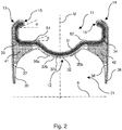
- the rim 10 comprises a radially outer peripheral channel 11 and a radially inner closed channel 21.
- the peripheral channel 11 comprises an upper bridge 12, extending between two opposite wings 13 and 14, adapted for holding a tyre; the wings 13 and 14 are provided with respective rounded ends 15 and 16, folded towards one another so as to form an acute angle ⁇ equal to about 20° with respect to a direction A parallel to the axis of the rim 10.
- the closed channel 21 extends in a radially inner position from the upper bridge 12 and comprises two side walls (or flanks) 23 and 24, joined together by the upper bridge 12 and by a lower bridge 25.
- the peripheral channel 11 comprises an inner layered structure 31, extending through the entire upper bridge 12 from the wing 13 to the wing 14, and a wrapping layered structure 32.
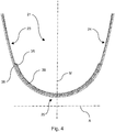
- the wrapping layered structure 32 is wound around the inner layered structure 31 and closed on itself so as to completely surround the inner layered structure 31, as visible in fig. 1 and even better in fig. 2 .
- the wrapping layered structure 32 comprises an initial flap 32a and a final flap 32b, overlapped one another at the mid-plane M of the rim 10, in a radially inner position with respect to the upper bridge 12.
- the peripheral channel also comprises two inner wing layered structures 33 and 34 (visible in figures 1 , 2 and particularly 3), arranged between the inner layered structure 31 and the wrapping layered structure 32 at each of the wings 13 and 14, and partially also at the upper bridge 12.
- the closed channel 21 comprises a closed channel layered structure 35, extending along the side walls 23 and 24, along the lower bridge 25 and at least partially along the upper bridge 12.
- the closed channel layered structure 35 comprises an initial flap 35a and a final flap 35b, which are arranged at the upper bridge 12 and are juxtaposed to the wrapping layered structure 32.
- the two flaps 35a and 35b are spaced from one another, so that the wrapping layered structure 32 remains facing towards the inside of the closed channel 21, in particular with its flap 32b overlapping the flap 32a.
- the closed channel layered structure 35 does not contribute to increasing the thickness of the upper bridge 12 where the wrapping layered structure 32 already has a thickening due to the overlapping of the two flaps 32a and 32b; moreover, in making the rim 10 (which will be discussed hereinafter), the flaps 35a and 35b can more easily slide in the mold during forming, before curing.
- the closed channel layered structure 135 has overlapped initial and final flaps 135a, 135b. In this way, the closed channel layered structure 135 is closed on itself to form a completely box-like and thus particularly rigid structure.
- the rim 10 also comprises an outer layered structure 36, extending externally in the rim 10 from the wing 13, to the side wall 23, to the lower bridge 25, to the side wall 24, up to the wing 14.
- the outer layered structure 36 overlaps the wrapping layered structure 32 at the wings 13 and 14 and over the closed channel layered structure 35 at the closed channel 21.
- the rim 10 also comprises two outer wing layered structures 37 and 38 (visible in figures 1 , 2 and particularly 3), each of which is arranged between the outer layered structure 36 and both the wrapping layered structure 32, at each of the wings 13 and 14, and the closed channel layered structure 35, at the side walls 23 and 24 of the closed channel 21.
- the rim 10 comprises a lower bridge layered structure 39 (visible in figure 1 and particularly in figure 4 ), extending at the lower bridge 25 and arranged between the closed channel layered structure 35 and the outer layered structure 36.
- the lower bridge layered structure 239 overlaps the closed channel layered structure 35, inside the closed channel 21, i.e. on the opposite side with respect to the outer layered structure 36.
- the rim 10 also comprises two circumferential inserts 41 and 42, arranged in the two convergence areas between the upper bridge 12, the wings 13 and 14, and the side walls 23 and 24.
- These circumferential inserts 41 and 42 are formed with directional structural fibres oriented in the circumferential direction of the rim 10, incorporated in polymeric material.
- the circumferential inserts 41 and 42 are inserted in the structure of the rim 10 between the wrapping layered structure 32 and the closed channel layered structure 35, below the outer wing layered structures 37 and 38 and below the outer layered structure 36.
- the layered structures 31-39 are each made with one or more layers of structural fibres, preferably directional structural fibres.
- the peripheral channel 11 comprises a pair of circumferential projections 51 and 52, each of which has a surface inclined by an acute angle ⁇ with respect to the direction A parallel to the rotation axis of the rim 10.
- the angle ⁇ is slightly smaller, by 0.5-4 degrees, preferably by about 2 degrees.
- the projections 51 and 52 are formed with the wrapping layered structure 32, through corresponding grooves formed in the forming mold; during forming, the polymeric material of the wrapping layered structure 32 fills such grooves and forms the projections 51 and 52. Given the very limited stresses that the projections 51 and 52 must withstand, it is not necessary to take care that the structural fibres of the wrapping layered structure 32 also enter into the grooves during forming and are thus incorporated in the projections themselves.
- the grooves of the mold corresponding to the projections 51 and 52 can be filled by polymeric material, in particular a thermosetting resin.
- the rim 10 can be made with one of the methods known in the field, for example with a radial mold according to the teachings of EP 1231077B2 .
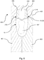
- the rim 10 is made in the following way, illustrated with reference to figures 8 and 9 .
- a radial mold 400 is provided, shaped according to the profile of the rim 10.
- This mold 400 thus comprises (in a corresponding manner to the teachings of EP 1231077B2 ) a pair of radially inner shells 401 and 402, shaped so as to define the radially inner profile of the rim 10 (i.e.
- a radially outer shell 403 provided with a central mold insert 404 (shaped so as to define the outer profile of the peripheral channel 11) and two mobile side mold inserts 405 and 406 (shaped so as to define the profile of the wings 13 and 14); both the radially outer shell 403, and the central mold insert 404 and the mobile side mold inserts 405 and 406 are made in sectors, for example three sectors of 120 degrees, so as to allow the extraction of the rim once formed.
- the mold 400 also comprises an inflatable and removable pression element 407, shaped to define the inner profile of the closed channel 21.
- the layered structures are arranged in uncured state to form the peripheral channel 11.
- the wrapping layered structure 32 is firstly laid on the work plane, then the inner layered structure 31 is overlapped, then the inner wing layered structures 33 and 34 are overlapped; the inner layered structure 31 has the same length as the wrapping layered structure 32 (substantially equal to the circumference of the rim 10 to be made) and smaller width, less than half the width of the wrapping layered structure 32; the inner layered structure 31 and the inner wing layered structures 33 and 34 are positioned so as to reach the same position in the width direction.
- the wrapping layered structure 32 is enclosed there on top, folding the two opposite flaps 32a and 32b above the inner layered structure 31 and overlapping them over one another. In this way, a first assembly of layered structures is arranged, which will form much of the peripheral channel 11.
- the pair of radially inner shells 401 and 402 is arranged so that they are coupled together.
- the outer layered structure 36, then the lower bridge layered structure 39, then the unfolded closed channel layered structure 35, then the pression element 407 are arranged; the closed channel layered structure 35 is then folded with its flaps 35a and 35b on the pression element 407.
- the circumferential inserts 41, 42, and finally the assembly described above are arranged in the mold 400 with the layered structures 31-34, already preformed folded in a C shape facing radially outwards.
- the mold 400 is closed, placing first the mobile side mold inserts 405 and 406, then the central mold insert 404 and finally the radially outer shell 403.
- the configuration represented in fig. 8 is thus reached. It should be noted that the layered structures 32 and 31 that will form the wings 13 and 14 occupy only in part, i.e. not completely, the space between the shells 401, 402, 403 and the mold inserts 405 and 406.
- the pression element 407 is activated (inflating it), so as to exert a pressure from the inside towards the outside on the layered structures arranged in the mold 400.
- this pressure pushes on the layered structures of the preformed assembly (the wrapping layered structure 32 with the inner layered structure 31 and the inner wing layered structures 33 and 34 inside), pushing and forcing the material towards the end areas of the mold 400, until the entire space between the shells 401, 402 and 403 and the mobile side mold inserts 405 and 406 is occupied.
- the closed channel layered structure 35 follows the dilation of the pression element 407, without particular obstacles thanks to the non-overlapping of the flaps 35a and 35b.
- the mold 400 is subjected to curing, i.e. it is subjected to predetermined pressure and temperature for a predetermined time, so as to cause the setting of the polymeric material.
- the mold 400 is opened and the mold inserts 404, 405 and 406 are removed; this operation is facilitated by the angles ⁇ and ⁇ indicated above. Finally, the rim 10 is removed from the mold 400.
- the ends 15 and 16 of the wings 13 and 14 are already provided with their final rounded shape, without the need for further mechanical processing.
- FIG. 5 shows a rim 310 analogous to the rim 10, but with a simplified structure, with a single channel.
- the rim 310 comprises a peripheral channel 311, with an upper bridge 312, extending between two opposite wings 313 and 314, adapted for holding a tyre; the wings 313 and 314 are provided with respective rounded ends 315 and 316, folded towards one another so as to form an acute angle ⁇ equal to about 20° with respect to a direction B parallel to the axis of the rim 310.
- the peripheral channel 311 comprises an inner layered structure 331, extending through the entire upper bridge 312 from the wing 313 to the wing 314, and a wrapping layered structure 332.
- the wrapping layered structure 332 is wound around the inner layered structure 331 and closed on itself so as to completely surround the inner layered structure 331.
- the wrapping layered structure 332 comprises an initial flap 332a and a final flap 332b, overlapping over one another at the mid-plane N of the rim 310, in a radially inner position with respect to the upper bridge 312.
- the peripheral channel also comprises two inner wing layered structures 333 and 334, arranged between the inner layered structure 331 and the wrapping layered structure 332 at each of the wings 313 and 314, and partially also of the upper bridge 312.
- the rim 310 also comprises an outer layered structure 336, extending externally in the rim 310 from the wing 313, to the upper bridge 312, up to the wing 314.
- the outer layered structure 336 overlaps the wrapping layered structure 332 at the wings 313 and 314.
- the rim 310 also comprises two outer wing layered structures 337 and 338, each of which is arranged between the outer layered structure 336 and the wrapping layered structure 332, at each of the wings 313 and 314.
- the rim 10 also comprises two circumferential inserts 341 and 342, arranged in the two convergence areas between the upper bridge 312 and the wings 313 and 314.
- These circumferential inserts 341 and 342 are formed with directional structural fibres oriented in the circumferential direction of the rim 310, incorporated in polymeric material.
- the circumferential inserts 341 and 342 are inserted in the structure of the rim 310 between the wrapping layered structure 332 and the outer layered structure 336, below the outer wing layered structures 337 and 338.
- the layered structures 331-338 are made in an analogous manner to the layered structures 31-38, each with one or more layers of structural fibres, preferably directional structural fibres.
- the peripheral channel 311 comprises a pair of circumferential projections 351 and 352, totally analogous to the projections 51 and 52 of the rim 10. Each of them has a surface inclined by an acute angle ⁇ with respect to the direction B parallel to the rotation axis of the rim 310. With respect to the angle ⁇ of inclination of the ends 315 and 316 of the wings 313 and 314, the angle ⁇ is slightly less, by 0.5-4 degrees, preferably by about 2 degrees.
- the rim 310 can be made with one of the methods known in the field, for example with a radial mold according to the teachings of EP 1231077B2 .
- the rim 310 is made in an analogous manner to the rim 10; in practice, the method is the same, except that of course all of the steps referring to the closed channel and to the lower bridge, which are not present here, are left out.
Landscapes
- Engineering & Computer Science (AREA)
- Mechanical Engineering (AREA)
- Chemical & Material Sciences (AREA)
- Materials Engineering (AREA)
- Composite Materials (AREA)
- Moulding By Coating Moulds (AREA)
Applications Claiming Priority (1)
| Application Number | Priority Date | Filing Date | Title |
|---|---|---|---|
| IT202000008644 | 2020-04-22 |
Publications (1)
| Publication Number | Publication Date |
|---|---|
| EP3900946A1 true EP3900946A1 (fr) | 2021-10-27 |
Family
ID=71111749
Family Applications (1)
| Application Number | Title | Priority Date | Filing Date |
|---|---|---|---|
| EP21168458.4A Pending EP3900946A1 (fr) | 2020-04-22 | 2021-04-14 | Jante de bicyclette en matériau composite avec des ailes à structure renforcée |
Country Status (5)
| Country | Link |
|---|---|
| US (1) | US11745538B2 (fr) |
| EP (1) | EP3900946A1 (fr) |
| JP (1) | JP2021178629A (fr) |
| CN (1) | CN113524977A (fr) |
| TW (1) | TW202146216A (fr) |
Citations (4)
| Publication number | Priority date | Publication date | Assignee | Title |
|---|---|---|---|---|
| EP1506882B1 (fr) | 2003-08-11 | 2008-07-09 | Campagnolo Srl | Jante composite de bicyclette et procédé de sa fabrication |
| EP2062747A2 (fr) * | 2007-11-26 | 2009-05-27 | CAMPAGNOLO S.r.l. | Jante pour une roue de bicyclette et roue de bicyclette comprenant une telle jante |
| EP1231077B2 (fr) | 2001-02-13 | 2015-08-26 | Campagnolo S.R.L. | Méthode de fabrication d'une jante de bicyclette et jante de roue de bicyclette ainsi obtenue |
| US9718305B2 (en) * | 2015-04-14 | 2017-08-01 | Shimano Inc. | Bicycle rim |
Family Cites Families (9)
| Publication number | Priority date | Publication date | Assignee | Title |
|---|---|---|---|---|
| US5540485A (en) * | 1994-11-10 | 1996-07-30 | Enders; Mark L. | Composite bicycle wheel |
| US6347839B1 (en) * | 2000-09-25 | 2002-02-19 | Polymeric Corporation The | Composite rim |
| US8002362B2 (en) * | 2004-02-17 | 2011-08-23 | Trek Bicycle Corporation | Optimal thermal properties in light weight and high performance braking composite clincher or tubular tire bicycle wheel rim |
| DE102006010445B4 (de) * | 2006-03-03 | 2014-02-13 | Denk Engineering Gmbh | Felge |
| ITMI20071103A1 (it) * | 2007-05-30 | 2008-11-30 | Campagnolo Srl | Cerchio per ruota di bicicletta in materiale composito con indicatore di usura e ruota comprendente tale cerchio |
| FR2985217B1 (fr) * | 2012-01-04 | 2016-12-09 | Mavic Sas | Jante pour roue de cycle et son procede de fabrication |
| DE102015102465B4 (de) * | 2015-02-20 | 2021-01-21 | Carbovation Gmbh | Verfahren zur Herstellung eines Felgenringes, Verfahren zur Befestigung von Speichen, Felge, insbesondere Drahtreifenfelge und Fahrrad |
| CA3123100A1 (fr) * | 2017-12-13 | 2019-06-20 | Falcon Composites Corp. | Jantes de bicyclette et leurs procedes de fabrication |
| CN114746283A (zh) * | 2019-09-30 | 2022-07-12 | Css复合材料有限责任公司 | 增强的热塑性部件及其制造方法 |
-
2021
- 2021-04-14 EP EP21168458.4A patent/EP3900946A1/fr active Pending
- 2021-04-16 CN CN202110410804.9A patent/CN113524977A/zh active Pending
- 2021-04-19 TW TW110113901A patent/TW202146216A/zh unknown
- 2021-04-20 JP JP2021071241A patent/JP2021178629A/ja active Pending
- 2021-04-22 US US17/237,394 patent/US11745538B2/en active Active
Patent Citations (4)
| Publication number | Priority date | Publication date | Assignee | Title |
|---|---|---|---|---|
| EP1231077B2 (fr) | 2001-02-13 | 2015-08-26 | Campagnolo S.R.L. | Méthode de fabrication d'une jante de bicyclette et jante de roue de bicyclette ainsi obtenue |
| EP1506882B1 (fr) | 2003-08-11 | 2008-07-09 | Campagnolo Srl | Jante composite de bicyclette et procédé de sa fabrication |
| EP2062747A2 (fr) * | 2007-11-26 | 2009-05-27 | CAMPAGNOLO S.r.l. | Jante pour une roue de bicyclette et roue de bicyclette comprenant une telle jante |
| US9718305B2 (en) * | 2015-04-14 | 2017-08-01 | Shimano Inc. | Bicycle rim |
Also Published As
| Publication number | Publication date |
|---|---|
| TW202146216A (zh) | 2021-12-16 |
| US20210331518A1 (en) | 2021-10-28 |
| JP2021178629A (ja) | 2021-11-18 |
| CN113524977A (zh) | 2021-10-22 |
| US11745538B2 (en) | 2023-09-05 |
Similar Documents
| Publication | Publication Date | Title |
|---|---|---|
| EP3030428B1 (fr) | Roue fabriquée en matériau plastique renforcé de fibres | |
| US11407253B2 (en) | Bicycle rims and method of manufacture thereof | |
| US9688097B2 (en) | Method for producing composite bicycle rim | |
| EP1231077B2 (fr) | Méthode de fabrication d'une jante de bicyclette et jante de roue de bicyclette ainsi obtenue | |
| CA2866552C (fr) | Procede de fabrication de corps de cylindre en une seule piece dans un materiau composite | |
| KR101514585B1 (ko) | Smp 장치를 가지고 일체구조의 복합 부품들을 제조하기 위한 방법과 시스템들 | |
| US20070187866A1 (en) | Process for the production of a crank lever for a bicycle | |
| CA1264908A (fr) | Corps creux arme de fibres, et sa fabrication | |
| US7361296B2 (en) | Motor vehicle wheel frame | |
| JPH0365317A (ja) | 複合構造体を形成するための方法及び装置 | |
| KR19980042411A (ko) | 림 프리폼의 제조방법 및 장치 | |
| EP3495158B1 (fr) | Jante de roue de bicyclette et procédé de fabrication correspondant | |
| WO2019010931A1 (fr) | Arbre en matériau composite de forme spéciale, procédé de préparation s'y rapportant et procédé de liaison de l'arbre en matériau composite de forme spéciale et d'une bride métallique | |
| EP3900946A1 (fr) | Jante de bicyclette en matériau composite avec des ailes à structure renforcée | |
| AU2329192A (en) | A vehicle wheel and a method of fabricating same | |
| EP2746038B1 (fr) | Procédé de fabrication d'un composant structurel, composant structurel, coque, et aéronef ou engin spatial | |
| US3505447A (en) | Segmental tire mold and method of molding an asymmetric tire | |
| US20240165901A1 (en) | Grooved-core tooling for manufacturing pneumatic tires reinforced by stays passing through the inflation cavity | |
| US4064215A (en) | Method of manufacturing pneumatic tubular tires | |
| US3466211A (en) | Integral pneumatic tire and wheel construction and method of making the same | |
| US4692362A (en) | Fabric reinforced tubular rubber bladders and method of making same | |
| US3362451A (en) | Integral pneumatic tire and wheel construction and method of making the same | |
| WO2019166112A1 (fr) | Roue composite et son procédé de fabrication | |
| ZA200407753B (en) | Motor vehicle wheel frame. |
Legal Events
| Date | Code | Title | Description |
|---|---|---|---|
| PUAI | Public reference made under article 153(3) epc to a published international application that has entered the european phase |
Free format text: ORIGINAL CODE: 0009012 |
|
| STAA | Information on the status of an ep patent application or granted ep patent |
Free format text: STATUS: THE APPLICATION HAS BEEN PUBLISHED |
|
| AK | Designated contracting states |
Kind code of ref document: A1 Designated state(s): AL AT BE BG CH CY CZ DE DK EE ES FI FR GB GR HR HU IE IS IT LI LT LU LV MC MK MT NL NO PL PT RO RS SE SI SK SM TR |
|
| B565 | Issuance of search results under rule 164(2) epc |
Effective date: 20210907 |
|
| STAA | Information on the status of an ep patent application or granted ep patent |
Free format text: STATUS: REQUEST FOR EXAMINATION WAS MADE |
|
| 17P | Request for examination filed |
Effective date: 20220426 |
|
| RBV | Designated contracting states (corrected) |
Designated state(s): AL AT BE BG CH CY CZ DE DK EE ES FI FR GB GR HR HU IE IS IT LI LT LU LV MC MK MT NL NO PL PT RO RS SE SI SK SM TR |
|
| P01 | Opt-out of the competence of the unified patent court (upc) registered |
Effective date: 20230518 |
|
| STAA | Information on the status of an ep patent application or granted ep patent |
Free format text: STATUS: EXAMINATION IS IN PROGRESS |
|
| 17Q | First examination report despatched |
Effective date: 20231110 |