EP3900917B1 - Packing machine - Google Patents
Packing machine Download PDFInfo
- Publication number
- EP3900917B1 EP3900917B1 EP21169111.8A EP21169111A EP3900917B1 EP 3900917 B1 EP3900917 B1 EP 3900917B1 EP 21169111 A EP21169111 A EP 21169111A EP 3900917 B1 EP3900917 B1 EP 3900917B1
- Authority
- EP
- European Patent Office
- Prior art keywords
- guide member
- packaging material
- welded portion
- packing machine
- detection element
- Prior art date
- Legal status (The legal status is an assumption and is not a legal conclusion. Google has not performed a legal analysis and makes no representation as to the accuracy of the status listed.)
- Active
Links
Images



Classifications
-
- B—PERFORMING OPERATIONS; TRANSPORTING
- B29—WORKING OF PLASTICS; WORKING OF SUBSTANCES IN A PLASTIC STATE IN GENERAL
- B29C—SHAPING OR JOINING OF PLASTICS; SHAPING OF MATERIAL IN A PLASTIC STATE, NOT OTHERWISE PROVIDED FOR; AFTER-TREATMENT OF THE SHAPED PRODUCTS, e.g. REPAIRING
- B29C66/00—General aspects of processes or apparatus for joining preformed parts
- B29C66/40—General aspects of joining substantially flat articles, e.g. plates, sheets or web-like materials; Making flat seams in tubular or hollow articles; Joining single elements to substantially flat surfaces
- B29C66/49—Internally supporting the, e.g. tubular, article during joining
-
- B—PERFORMING OPERATIONS; TRANSPORTING
- B65—CONVEYING; PACKING; STORING; HANDLING THIN OR FILAMENTARY MATERIAL
- B65B—MACHINES, APPARATUS OR DEVICES FOR, OR METHODS OF, PACKAGING ARTICLES OR MATERIALS; UNPACKING
- B65B43/00—Forming, feeding, opening or setting-up containers or receptacles in association with packaging
- B65B43/08—Forming three-dimensional [3D] containers from sheet material
-
- B—PERFORMING OPERATIONS; TRANSPORTING
- B29—WORKING OF PLASTICS; WORKING OF SUBSTANCES IN A PLASTIC STATE IN GENERAL
- B29C—SHAPING OR JOINING OF PLASTICS; SHAPING OF MATERIAL IN A PLASTIC STATE, NOT OTHERWISE PROVIDED FOR; AFTER-TREATMENT OF THE SHAPED PRODUCTS, e.g. REPAIRING
- B29C66/00—General aspects of processes or apparatus for joining preformed parts
- B29C66/80—General aspects of machine operations or constructions and parts thereof
- B29C66/84—Specific machine types or machines suitable for specific applications
- B29C66/849—Packaging machines
-
- B—PERFORMING OPERATIONS; TRANSPORTING
- B29—WORKING OF PLASTICS; WORKING OF SUBSTANCES IN A PLASTIC STATE IN GENERAL
- B29C—SHAPING OR JOINING OF PLASTICS; SHAPING OF MATERIAL IN A PLASTIC STATE, NOT OTHERWISE PROVIDED FOR; AFTER-TREATMENT OF THE SHAPED PRODUCTS, e.g. REPAIRING
- B29C65/00—Joining or sealing of preformed parts, e.g. welding of plastics materials; Apparatus therefor
- B29C65/02—Joining or sealing of preformed parts, e.g. welding of plastics materials; Apparatus therefor by heating, with or without pressure
-
- B—PERFORMING OPERATIONS; TRANSPORTING
- B29—WORKING OF PLASTICS; WORKING OF SUBSTANCES IN A PLASTIC STATE IN GENERAL
- B29C—SHAPING OR JOINING OF PLASTICS; SHAPING OF MATERIAL IN A PLASTIC STATE, NOT OTHERWISE PROVIDED FOR; AFTER-TREATMENT OF THE SHAPED PRODUCTS, e.g. REPAIRING
- B29C65/00—Joining or sealing of preformed parts, e.g. welding of plastics materials; Apparatus therefor
- B29C65/02—Joining or sealing of preformed parts, e.g. welding of plastics materials; Apparatus therefor by heating, with or without pressure
- B29C65/08—Joining or sealing of preformed parts, e.g. welding of plastics materials; Apparatus therefor by heating, with or without pressure using ultrasonic vibrations
-
- B—PERFORMING OPERATIONS; TRANSPORTING
- B29—WORKING OF PLASTICS; WORKING OF SUBSTANCES IN A PLASTIC STATE IN GENERAL
- B29C—SHAPING OR JOINING OF PLASTICS; SHAPING OF MATERIAL IN A PLASTIC STATE, NOT OTHERWISE PROVIDED FOR; AFTER-TREATMENT OF THE SHAPED PRODUCTS, e.g. REPAIRING
- B29C65/00—Joining or sealing of preformed parts, e.g. welding of plastics materials; Apparatus therefor
- B29C65/78—Means for handling the parts to be joined, e.g. for making containers or hollow articles, e.g. means for handling sheets, plates, web-like materials, tubular articles, hollow articles or elements to be joined therewith; Means for discharging the joined articles from the joining apparatus
-
- B—PERFORMING OPERATIONS; TRANSPORTING
- B29—WORKING OF PLASTICS; WORKING OF SUBSTANCES IN A PLASTIC STATE IN GENERAL
- B29C—SHAPING OR JOINING OF PLASTICS; SHAPING OF MATERIAL IN A PLASTIC STATE, NOT OTHERWISE PROVIDED FOR; AFTER-TREATMENT OF THE SHAPED PRODUCTS, e.g. REPAIRING
- B29C65/00—Joining or sealing of preformed parts, e.g. welding of plastics materials; Apparatus therefor
- B29C65/82—Testing the joint
-
- B—PERFORMING OPERATIONS; TRANSPORTING
- B29—WORKING OF PLASTICS; WORKING OF SUBSTANCES IN A PLASTIC STATE IN GENERAL
- B29C—SHAPING OR JOINING OF PLASTICS; SHAPING OF MATERIAL IN A PLASTIC STATE, NOT OTHERWISE PROVIDED FOR; AFTER-TREATMENT OF THE SHAPED PRODUCTS, e.g. REPAIRING
- B29C65/00—Joining or sealing of preformed parts, e.g. welding of plastics materials; Apparatus therefor
- B29C65/82—Testing the joint
- B29C65/8207—Testing the joint by mechanical methods
-
- B—PERFORMING OPERATIONS; TRANSPORTING
- B29—WORKING OF PLASTICS; WORKING OF SUBSTANCES IN A PLASTIC STATE IN GENERAL
- B29C—SHAPING OR JOINING OF PLASTICS; SHAPING OF MATERIAL IN A PLASTIC STATE, NOT OTHERWISE PROVIDED FOR; AFTER-TREATMENT OF THE SHAPED PRODUCTS, e.g. REPAIRING
- B29C66/00—General aspects of processes or apparatus for joining preformed parts
- B29C66/01—General aspects dealing with the joint area or with the area to be joined
- B29C66/05—Particular design of joint configurations
- B29C66/10—Particular design of joint configurations particular design of the joint cross-sections
- B29C66/13—Single flanged joints; Fin-type joints; Single hem joints; Edge joints; Interpenetrating fingered joints; Other specific particular designs of joint cross-sections not provided for in groups B29C66/11 - B29C66/12
- B29C66/133—Fin-type joints, the parts to be joined being flexible
-
- B—PERFORMING OPERATIONS; TRANSPORTING
- B29—WORKING OF PLASTICS; WORKING OF SUBSTANCES IN A PLASTIC STATE IN GENERAL
- B29C—SHAPING OR JOINING OF PLASTICS; SHAPING OF MATERIAL IN A PLASTIC STATE, NOT OTHERWISE PROVIDED FOR; AFTER-TREATMENT OF THE SHAPED PRODUCTS, e.g. REPAIRING
- B29C66/00—General aspects of processes or apparatus for joining preformed parts
- B29C66/40—General aspects of joining substantially flat articles, e.g. plates, sheets or web-like materials; Making flat seams in tubular or hollow articles; Joining single elements to substantially flat surfaces
- B29C66/41—Joining substantially flat articles ; Making flat seams in tubular or hollow articles
- B29C66/43—Joining a relatively small portion of the surface of said articles
- B29C66/432—Joining a relatively small portion of the surface of said articles for making tubular articles or closed loops, e.g. by joining several sheets ; for making hollow articles or hollow preforms
- B29C66/4322—Joining a relatively small portion of the surface of said articles for making tubular articles or closed loops, e.g. by joining several sheets ; for making hollow articles or hollow preforms by joining a single sheet to itself
-
- B—PERFORMING OPERATIONS; TRANSPORTING
- B29—WORKING OF PLASTICS; WORKING OF SUBSTANCES IN A PLASTIC STATE IN GENERAL
- B29C—SHAPING OR JOINING OF PLASTICS; SHAPING OF MATERIAL IN A PLASTIC STATE, NOT OTHERWISE PROVIDED FOR; AFTER-TREATMENT OF THE SHAPED PRODUCTS, e.g. REPAIRING
- B29C66/00—General aspects of processes or apparatus for joining preformed parts
- B29C66/70—General aspects of processes or apparatus for joining preformed parts characterised by the composition, physical properties or the structure of the material of the parts to be joined; Joining with non-plastics material
- B29C66/72—General aspects of processes or apparatus for joining preformed parts characterised by the composition, physical properties or the structure of the material of the parts to be joined; Joining with non-plastics material characterised by the structure of the material of the parts to be joined
- B29C66/729—Textile or other fibrous material made from plastics
- B29C66/7294—Non woven mats, e.g. felt
-
- B—PERFORMING OPERATIONS; TRANSPORTING
- B29—WORKING OF PLASTICS; WORKING OF SUBSTANCES IN A PLASTIC STATE IN GENERAL
- B29C—SHAPING OR JOINING OF PLASTICS; SHAPING OF MATERIAL IN A PLASTIC STATE, NOT OTHERWISE PROVIDED FOR; AFTER-TREATMENT OF THE SHAPED PRODUCTS, e.g. REPAIRING
- B29C66/00—General aspects of processes or apparatus for joining preformed parts
- B29C66/70—General aspects of processes or apparatus for joining preformed parts characterised by the composition, physical properties or the structure of the material of the parts to be joined; Joining with non-plastics material
- B29C66/73—General aspects of processes or apparatus for joining preformed parts characterised by the composition, physical properties or the structure of the material of the parts to be joined; Joining with non-plastics material characterised by the intensive physical properties of the material of the parts to be joined, by the optical properties of the material of the parts to be joined, by the extensive physical properties of the parts to be joined, by the state of the material of the parts to be joined or by the material of the parts to be joined being a thermoplastic or a thermoset
- B29C66/739—General aspects of processes or apparatus for joining preformed parts characterised by the composition, physical properties or the structure of the material of the parts to be joined; Joining with non-plastics material characterised by the intensive physical properties of the material of the parts to be joined, by the optical properties of the material of the parts to be joined, by the extensive physical properties of the parts to be joined, by the state of the material of the parts to be joined or by the material of the parts to be joined being a thermoplastic or a thermoset characterised by the material of the parts to be joined being a thermoplastic or a thermoset
- B29C66/7392—General aspects of processes or apparatus for joining preformed parts characterised by the composition, physical properties or the structure of the material of the parts to be joined; Joining with non-plastics material characterised by the intensive physical properties of the material of the parts to be joined, by the optical properties of the material of the parts to be joined, by the extensive physical properties of the parts to be joined, by the state of the material of the parts to be joined or by the material of the parts to be joined being a thermoplastic or a thermoset characterised by the material of the parts to be joined being a thermoplastic or a thermoset characterised by the material of at least one of the parts being a thermoplastic
- B29C66/73921—General aspects of processes or apparatus for joining preformed parts characterised by the composition, physical properties or the structure of the material of the parts to be joined; Joining with non-plastics material characterised by the intensive physical properties of the material of the parts to be joined, by the optical properties of the material of the parts to be joined, by the extensive physical properties of the parts to be joined, by the state of the material of the parts to be joined or by the material of the parts to be joined being a thermoplastic or a thermoset characterised by the material of the parts to be joined being a thermoplastic or a thermoset characterised by the material of at least one of the parts being a thermoplastic characterised by the materials of both parts being thermoplastics
-
- B—PERFORMING OPERATIONS; TRANSPORTING
- B29—WORKING OF PLASTICS; WORKING OF SUBSTANCES IN A PLASTIC STATE IN GENERAL
- B29C—SHAPING OR JOINING OF PLASTICS; SHAPING OF MATERIAL IN A PLASTIC STATE, NOT OTHERWISE PROVIDED FOR; AFTER-TREATMENT OF THE SHAPED PRODUCTS, e.g. REPAIRING
- B29C66/00—General aspects of processes or apparatus for joining preformed parts
- B29C66/80—General aspects of machine operations or constructions and parts thereof
- B29C66/83—General aspects of machine operations or constructions and parts thereof characterised by the movement of the joining or pressing tools
- B29C66/836—Moving relative to and tangentially to the parts to be joined, e.g. transversely to the displacement of the parts to be joined, e.g. using a X-Y table
-
- B—PERFORMING OPERATIONS; TRANSPORTING
- B29—WORKING OF PLASTICS; WORKING OF SUBSTANCES IN A PLASTIC STATE IN GENERAL
- B29C—SHAPING OR JOINING OF PLASTICS; SHAPING OF MATERIAL IN A PLASTIC STATE, NOT OTHERWISE PROVIDED FOR; AFTER-TREATMENT OF THE SHAPED PRODUCTS, e.g. REPAIRING
- B29C66/00—General aspects of processes or apparatus for joining preformed parts
- B29C66/90—Measuring or controlling the joining process
- B29C66/97—Checking completion of joining or correct joining by using indications on at least one of the joined parts
-
- B—PERFORMING OPERATIONS; TRANSPORTING
- B65—CONVEYING; PACKING; STORING; HANDLING THIN OR FILAMENTARY MATERIAL
- B65B—MACHINES, APPARATUS OR DEVICES FOR, OR METHODS OF, PACKAGING ARTICLES OR MATERIALS; UNPACKING
- B65B51/00—Devices for, or methods of, sealing or securing package folds or closures; Devices for gathering or twisting wrappers, or necks of bags
- B65B51/10—Applying or generating heat or pressure or combinations thereof
-
- B—PERFORMING OPERATIONS; TRANSPORTING
- B65—CONVEYING; PACKING; STORING; HANDLING THIN OR FILAMENTARY MATERIAL
- B65B—MACHINES, APPARATUS OR DEVICES FOR, OR METHODS OF, PACKAGING ARTICLES OR MATERIALS; UNPACKING
- B65B51/00—Devices for, or methods of, sealing or securing package folds or closures; Devices for gathering or twisting wrappers, or necks of bags
- B65B51/10—Applying or generating heat or pressure or combinations thereof
- B65B51/22—Applying or generating heat or pressure or combinations thereof by friction or ultrasonic or high-frequency electrical means
- B65B51/225—Applying or generating heat or pressure or combinations thereof by friction or ultrasonic or high-frequency electrical means by ultrasonic welding
-
- B—PERFORMING OPERATIONS; TRANSPORTING
- B65—CONVEYING; PACKING; STORING; HANDLING THIN OR FILAMENTARY MATERIAL
- B65B—MACHINES, APPARATUS OR DEVICES FOR, OR METHODS OF, PACKAGING ARTICLES OR MATERIALS; UNPACKING
- B65B51/00—Devices for, or methods of, sealing or securing package folds or closures; Devices for gathering or twisting wrappers, or necks of bags
- B65B51/10—Applying or generating heat or pressure or combinations thereof
- B65B51/26—Devices specially adapted for producing transverse or longitudinal seams in webs or tubes
-
- B—PERFORMING OPERATIONS; TRANSPORTING
- B65—CONVEYING; PACKING; STORING; HANDLING THIN OR FILAMENTARY MATERIAL
- B65B—MACHINES, APPARATUS OR DEVICES FOR, OR METHODS OF, PACKAGING ARTICLES OR MATERIALS; UNPACKING
- B65B51/00—Devices for, or methods of, sealing or securing package folds or closures; Devices for gathering or twisting wrappers, or necks of bags
- B65B51/10—Applying or generating heat or pressure or combinations thereof
- B65B51/26—Devices specially adapted for producing transverse or longitudinal seams in webs or tubes
- B65B51/30—Devices, e.g. jaws, for applying pressure and heat, e.g. for subdividing filled tubes
-
- B—PERFORMING OPERATIONS; TRANSPORTING
- B65—CONVEYING; PACKING; STORING; HANDLING THIN OR FILAMENTARY MATERIAL
- B65B—MACHINES, APPARATUS OR DEVICES FOR, OR METHODS OF, PACKAGING ARTICLES OR MATERIALS; UNPACKING
- B65B57/00—Automatic control, checking, warning, or safety devices
- B65B57/02—Automatic control, checking, warning, or safety devices responsive to absence, presence, abnormal feed, or misplacement of binding or wrapping material, containers, or packages
-
- B—PERFORMING OPERATIONS; TRANSPORTING
- B65—CONVEYING; PACKING; STORING; HANDLING THIN OR FILAMENTARY MATERIAL
- B65B—MACHINES, APPARATUS OR DEVICES FOR, OR METHODS OF, PACKAGING ARTICLES OR MATERIALS; UNPACKING
- B65B57/00—Automatic control, checking, warning, or safety devices
- B65B57/10—Automatic control, checking, warning, or safety devices responsive to absence, presence, abnormal feed, or misplacement of articles or materials to be packaged
-
- B—PERFORMING OPERATIONS; TRANSPORTING
- B65—CONVEYING; PACKING; STORING; HANDLING THIN OR FILAMENTARY MATERIAL
- B65B—MACHINES, APPARATUS OR DEVICES FOR, OR METHODS OF, PACKAGING ARTICLES OR MATERIALS; UNPACKING
- B65B61/00—Auxiliary devices, not otherwise provided for, for operating on sheets, blanks, webs, binding material, containers or packages
- B65B61/04—Auxiliary devices, not otherwise provided for, for operating on sheets, blanks, webs, binding material, containers or packages for severing webs, or for separating joined packages
- B65B61/06—Auxiliary devices, not otherwise provided for, for operating on sheets, blanks, webs, binding material, containers or packages for severing webs, or for separating joined packages by cutting
-
- B—PERFORMING OPERATIONS; TRANSPORTING
- B65—CONVEYING; PACKING; STORING; HANDLING THIN OR FILAMENTARY MATERIAL
- B65B—MACHINES, APPARATUS OR DEVICES FOR, OR METHODS OF, PACKAGING ARTICLES OR MATERIALS; UNPACKING
- B65B9/00—Enclosing successive articles, or quantities of material, e.g. liquids or semiliquids, in flat, folded, or tubular webs of flexible sheet material; Subdividing filled flexible tubes to form packages
- B65B9/10—Enclosing successive articles, or quantities of material, in preformed tubular webs, or in webs formed into tubes around filling nozzles, e.g. extruded tubular webs
-
- B—PERFORMING OPERATIONS; TRANSPORTING
- B65—CONVEYING; PACKING; STORING; HANDLING THIN OR FILAMENTARY MATERIAL
- B65B—MACHINES, APPARATUS OR DEVICES FOR, OR METHODS OF, PACKAGING ARTICLES OR MATERIALS; UNPACKING
- B65B9/00—Enclosing successive articles, or quantities of material, e.g. liquids or semiliquids, in flat, folded, or tubular webs of flexible sheet material; Subdividing filled flexible tubes to form packages
- B65B9/10—Enclosing successive articles, or quantities of material, in preformed tubular webs, or in webs formed into tubes around filling nozzles, e.g. extruded tubular webs
- B65B9/20—Enclosing successive articles, or quantities of material, in preformed tubular webs, or in webs formed into tubes around filling nozzles, e.g. extruded tubular webs the webs being formed into tubes in situ around the filling nozzles
-
- B—PERFORMING OPERATIONS; TRANSPORTING
- B29—WORKING OF PLASTICS; WORKING OF SUBSTANCES IN A PLASTIC STATE IN GENERAL
- B29C—SHAPING OR JOINING OF PLASTICS; SHAPING OF MATERIAL IN A PLASTIC STATE, NOT OTHERWISE PROVIDED FOR; AFTER-TREATMENT OF THE SHAPED PRODUCTS, e.g. REPAIRING
- B29C66/00—General aspects of processes or apparatus for joining preformed parts
- B29C66/01—General aspects dealing with the joint area or with the area to be joined
- B29C66/05—Particular design of joint configurations
- B29C66/10—Particular design of joint configurations particular design of the joint cross-sections
- B29C66/11—Joint cross-sections comprising a single joint-segment, i.e. one of the parts to be joined comprising a single joint-segment in the joint cross-section
- B29C66/112—Single lapped joints
- B29C66/1122—Single lap to lap joints, i.e. overlap joints
-
- B—PERFORMING OPERATIONS; TRANSPORTING
- B29—WORKING OF PLASTICS; WORKING OF SUBSTANCES IN A PLASTIC STATE IN GENERAL
- B29C—SHAPING OR JOINING OF PLASTICS; SHAPING OF MATERIAL IN A PLASTIC STATE, NOT OTHERWISE PROVIDED FOR; AFTER-TREATMENT OF THE SHAPED PRODUCTS, e.g. REPAIRING
- B29C66/00—General aspects of processes or apparatus for joining preformed parts
- B29C66/40—General aspects of joining substantially flat articles, e.g. plates, sheets or web-like materials; Making flat seams in tubular or hollow articles; Joining single elements to substantially flat surfaces
- B29C66/41—Joining substantially flat articles ; Making flat seams in tubular or hollow articles
- B29C66/43—Joining a relatively small portion of the surface of said articles
- B29C66/431—Joining the articles to themselves
- B29C66/4312—Joining the articles to themselves for making flat seams in tubular or hollow articles, e.g. transversal seams
-
- B—PERFORMING OPERATIONS; TRANSPORTING
- B29—WORKING OF PLASTICS; WORKING OF SUBSTANCES IN A PLASTIC STATE IN GENERAL
- B29L—INDEXING SCHEME ASSOCIATED WITH SUBCLASS B29C, RELATING TO PARTICULAR ARTICLES
- B29L2031/00—Other particular articles
- B29L2031/712—Containers; Packaging elements or accessories, Packages
- B29L2031/7122—Tea bags
Definitions
- the present invention relates to a packing machine for manufacturing a package by forming a continuously supplied strip sheet into a tubular shape and sealing any overlapping portion.
- a packing machine in which a strip of film that is continuously supplied is formed into a tubular shape, and an overlapping portion is welded to form a fusion line.
- cross-sectional tension is applied to the film by an expansion ring having a diameter larger than the diameter of the tubular film arranged inside the welded tubular film immediately after welding to adjust the weld conditions at the overlapping portion, see Japanese Published Examined Patent Application No. H08-025543 corresponding to Japanese Patent No. 2119061 .
- Other examples of the prior art can be found in documents DE 10 2007 022854 A1 and GB 2 098 338 A .
- One aspect of the present invention is the capability of detecting a defective seal of a welded portion of a sheet of packaging material, which is continuously supplied and formed into a tubular shape, without imposing a large load on the packaging material.
- a packing machine includes a guide member for guiding a sheet of packaging material formed in a tubular shape; a sealing device for fusing an overlapping portion of the packaging material; a detection element provided downstream of the sealing device that is pivotally attached to the guide member and arranged along a welded portion of the packaging material; a biasing member for biasing the detection element outwardly from the guide member; and a detector for detecting the detection element that is pushed out from the welded portion.
- the packing machine may further include a determiner that determines if there is a seal defect in the welded portion when the detection piece is pushed out from the welded portion.
- the detector may include a proximity sensor that detects a proximity of a tip of the detection element.
- the tip of the detection element may be configured to protrude convexly toward the welded portion.
- Fig. 1 is a perspective view of a packing machine, which is an embodiment of the present invention.
- Fig. 2A is a front view around a guide portion in which the packaging material is wrapped around in a tubular shape, and
- Fig. 2B is a side view thereof.
- the packaging material S which is a strip of a continuously supplied sheet of non-woven fabric, is wrapped around a cylindrical guide member 12 and an overlapping portion in the vertical direction is fused (vertically sealed) to form a tubular package.
- the tubular package is then fused in the lateral direction and filled with contents to provide a tetrahedral-shaped extraction bag.
- fusing means cutting the fabric while it is being welded.
- the guide member 12 also functions as a filling nozzle for supplying the contents to be filled in the package.
- a hopper 14 that supplies the contents into the guide member 12 is provided at the upper end of the vertically arranged guide member 12.
- a conventional forming guide 16 is provided around the circumference of an upper portion of the guide member 12.
- the forming guide 16 bends the packaging material S, which is supplied as a strip sheet from the side, and wraps it around the circumference of the guide member 12.
- the packaging material S supplied from the side is bent downward by the forming guide 16 and wrapped around the cylindrical guide member 12 to be formed into a tubular shape.
- both sides of the strip of packaging material S are overlapped with a predetermined width along the longitudinal direction of the guide member 12 so that the inner surfaces of the sheet edges are brought into close contact with each other (overlapping portion) .
- the packaging material S is then fed downward along the guide member 12 while maintaining the same conditions.
- a sealing device (sealing means) 18 is arranged adjacent to the guide member 12 at a position corresponding to the overlapping portion of the packaging material S, below (downstream side) the forming guide 16.
- the sealing device 18 is, for example, a device for fusing the overlapping portion and includes an ultrasonic horn 18A and an anvil 18B facing the ultrasonic horn 18A.
- the ultrasonic horn 18A and the anvil 18B are so arranged to nip the overlapping portion of the packaging material S traveling along the guide member 12.
- the overlapping portion of the packaging material S is fused by passing between the ultrasonic horn 18A and the anvil 18B so that a weld (fusion line) M is provided in the packaging material.
- the guide member 12 of the present embodiment is provided with a detection dog (detection element) 20 at a position corresponding to the welded portion M of the packaging material S below (downstream side) the sealing device 18.
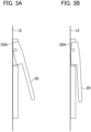
- Fig. 3A and Fig. 3B are enlarged side views showing the detection dog 20 in different states.
- the detection dog 20 is arranged along the longitudinal direction of the guide member 12 in order to be arranged along the welded portion M.
- An upper end (upstream end) of the detection dog 20 is attached to the side surface of the guide member 12 so as to pivot about the horizontal axis.
- a lower end (downstream end) of the detection dog 20 is urged by a biasing member (not shown) so as to extend outward.
- Fig. 3A illustrates a state when the detection dog 20 is pushed outward by the biasing force.
- Fig. 3B illustrates when the detection dog 20 is pressed against the guide member 12 resisting the biasing force.
- Configured at the upper end of the detection dog 20 is an abutting portion 20A that engages with the guide member 12 to restrict the pivot angle when the detection dog 20 is extended toward the welded portion M, see the state in Fig. 3A .
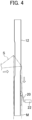
- Fig. 4 is a side view of the guide member, illustrating a state when the detection dog 20 protrudes from the welded portion M of the packaging material S, which is formed into a tubular shape.
- a proximity sensor (detector) 22 is arranged at a predetermined distance from the guide member 12 and faces the detection dog 20.
- the proximity sensor 22 detects the proximity of the detection dog 20 to determine whether or not the lower end portion of the detection dog 20 has been pushed out from the welded portion M (detection means). Signals from the proximity sensor 22 are sent to a control unit (not shown).
- a pair of feed rollers 24 are arranged for feeding the tubular packaging material S downward along the guide member 12.
- the pair of feed rollers 24, which are arranged to sandwich the guide member 12 from both sides, are rotated about the horizontal axis in opposite directions at the same speed.
- the tubular packaging material S surrounding the guide member 12 is held between the guide member 12 and the feed roller 24 on both sides of the guide member 12, and is synchronously fed downward by the feed rollers 24.
- a horizontal sealing device is provided to nip the tubular packaging material S in a direction crossing the longitudinal axis of the tubular sheet and to fuse (horizontally seal) the packaging material S.
- the contents of the package are then supplied through the guide member 12.
- the tubular package is again laterally sealed at the position above where the contents accumulated on the previously sealed portion so that a tetrahedral-shaped extraction bag is produced containing the contents inside.
- the contents are, for example, green tea or black tea.
- the detection dog 20 When the overlapping portion (overlapping allowance) is properly welded by the sealing device 18, the detection dog 20 is kept inside the tubular packaging material S against the biasing force. As a result, the detection dog 20 is arranged substantially along the longitudinal direction of the guide member 12. However, when the overlapping portion is not properly welded, the lower end portion of the detection dog 20 is pushed outward by the biasing force through an interstice between both side edges (overlapping portions) of the packaging material S. Thereby, the lower end of the detection dog 20 is detected by the proximity sensor 22 and the control unit determines that a seal defect has occurred in the welded portion M (determiner).
- Fig. 5 is a side view around the guide member.
- the shape of the detection dog is different from that of the previous embodiment, but the other configurations are the same as those illustrated in the previous embodiment. Therefore, the same reference numerals are used and the descriptions thereof will be omitted.
- a detection dog 26 of the alternate example includes a protrusion 26A at the lower end that projects convexly toward the welded portion M.
- the tip of the protrusion 26A is formed, for example, in an arc shape so that friction with the inner peripheral surface of the tubular packaging material S is reduced.
- the protrusion 26A can protrude from the packaging material S even when the welded portion M has a small hole, which can be detected by the proximity sensor 22. Accordingly, a seal defect can be more precisely detected.
- a machine that manufactures a tetrahedral-shaped extraction bag containing contents, such as tea leaves or black tea, by applying a non-woven fabric as a packaging material
- the present invention is not limited to the foregoing embodiments. It may also be applied to cases in which a resin sheet is used to seal liquid contents or be applied to a three-sided seal or a four-sided sealed package containing any contents.
- the present disclosure relates to subject matter contained in Japanese Patent Application No. 2020-074969 (filed on April 20, 2020 ).
Landscapes
- Engineering & Computer Science (AREA)
- Mechanical Engineering (AREA)
- Textile Engineering (AREA)
- Containers And Plastic Fillers For Packaging (AREA)
- Package Closures (AREA)
Description
- The present invention relates to a packing machine for manufacturing a package by forming a continuously supplied strip sheet into a tubular shape and sealing any overlapping portion.
- A packing machine is known in which a strip of film that is continuously supplied is formed into a tubular shape, and an overlapping portion is welded to form a fusion line. In this machine, cross-sectional tension is applied to the film by an expansion ring having a diameter larger than the diameter of the tubular film arranged inside the welded tubular film immediately after welding to adjust the weld conditions at the overlapping portion, see
Japanese Published Examined Patent Application No. H08-025543 Japanese Patent No. 2119061
Other examples of the prior art can be found indocuments DE 10 2007 022854 A1 andGB 2 098 338 A - However, in the configuration of
Japanese Published Examined Patent Application No. H08-025543 - One aspect of the present invention is the capability of detecting a defective seal of a welded portion of a sheet of packaging material, which is continuously supplied and formed into a tubular shape, without imposing a large load on the packaging material.
- A packing machine according to the first aspect of the present invention includes a guide member for guiding a sheet of packaging material formed in a tubular shape; a sealing device for fusing an overlapping portion of the packaging material; a detection element provided downstream of the sealing device that is pivotally attached to the guide member and arranged along a welded portion of the packaging material; a biasing member for biasing the detection element outwardly from the guide member; and a detector for detecting the detection element that is pushed out from the welded portion.
- The packing machine may further include a determiner that determines if there is a seal defect in the welded portion when the detection piece is pushed out from the welded portion.
- The detector may include a proximity sensor that detects a proximity of a tip of the detection element.
- The tip of the detection element may be configured to protrude convexly toward the welded portion.
- The objects and advantages of the present invention may be better understood from the following description with references to the accompanying drawings in which:
-
Fig. 1 is a perspective view of a packing machine of a first embodiment of the present invention; -
Fig. 2A is a front view around a guide portion in which the packaging material is wrapped around in a tubular shape; -
Fig. 2B is a side view around the guide portion in which the packaging material is wrapped around in a tubular shape; -
Fig. 3A is an enlarged side view showing a detection dog; -
Fig. 3B is an enlarged side view showing the detection dog; -
Fig. 4 is a side view around the guide member when the detection dog is extended; and -
Fig. 5 is a side view around the guide member when a detection dog of an alternative example is applied. - The embodiments of the present invention are described below with references to examples shown in the drawings.
Fig. 1 is a perspective view of a packing machine, which is an embodiment of the present invention.Fig. 2A is a front view around a guide portion in which the packaging material is wrapped around in a tubular shape, andFig. 2B is a side view thereof. - In the
packing machine 10 of the present embodiment, the packaging material S, which is a strip of a continuously supplied sheet of non-woven fabric, is wrapped around acylindrical guide member 12 and an overlapping portion in the vertical direction is fused (vertically sealed) to form a tubular package. The tubular package is then fused in the lateral direction and filled with contents to provide a tetrahedral-shaped extraction bag. Here, fusing means cutting the fabric while it is being welded. Such a machine is conventionally known, as disclosed inJapanese Patent No. 5240482 guide member 12 also functions as a filling nozzle for supplying the contents to be filled in the package. For example, ahopper 14 that supplies the contents into theguide member 12 is provided at the upper end of the vertically arrangedguide member 12. - A conventional forming
guide 16 is provided around the circumference of an upper portion of theguide member 12. The formingguide 16 bends the packaging material S, which is supplied as a strip sheet from the side, and wraps it around the circumference of theguide member 12. The packaging material S supplied from the side is bent downward by the formingguide 16 and wrapped around thecylindrical guide member 12 to be formed into a tubular shape. At this time, both sides of the strip of packaging material S are overlapped with a predetermined width along the longitudinal direction of theguide member 12 so that the inner surfaces of the sheet edges are brought into close contact with each other (overlapping portion) . The packaging material S is then fed downward along theguide member 12 while maintaining the same conditions. - A sealing device (sealing means) 18 is arranged adjacent to the
guide member 12 at a position corresponding to the overlapping portion of the packaging material S, below (downstream side) the formingguide 16. Thesealing device 18 is, for example, a device for fusing the overlapping portion and includes anultrasonic horn 18A and ananvil 18B facing theultrasonic horn 18A. Theultrasonic horn 18A and theanvil 18B are so arranged to nip the overlapping portion of the packaging material S traveling along theguide member 12. The overlapping portion of the packaging material S is fused by passing between theultrasonic horn 18A and theanvil 18B so that a weld (fusion line) M is provided in the packaging material. - Furthermore, the
guide member 12 of the present embodiment is provided with a detection dog (detection element) 20 at a position corresponding to the welded portion M of the packaging material S below (downstream side) thesealing device 18.Fig. 3A and Fig. 3B are enlarged side views showing thedetection dog 20 in different states. - The
detection dog 20 is arranged along the longitudinal direction of theguide member 12 in order to be arranged along the welded portion M. An upper end (upstream end) of thedetection dog 20 is attached to the side surface of theguide member 12 so as to pivot about the horizontal axis. A lower end (downstream end) of thedetection dog 20 is urged by a biasing member (not shown) so as to extend outward.Fig. 3A illustrates a state when thedetection dog 20 is pushed outward by the biasing force.Fig. 3B illustrates when thedetection dog 20 is pressed against theguide member 12 resisting the biasing force. Configured at the upper end of thedetection dog 20 is anabutting portion 20A that engages with theguide member 12 to restrict the pivot angle when thedetection dog 20 is extended toward the welded portion M, see the state inFig. 3A . -
Fig. 4 is a side view of the guide member, illustrating a state when thedetection dog 20 protrudes from the welded portion M of the packaging material S, which is formed into a tubular shape. At substantially the same height as the lower end of thedetection dog 20, a proximity sensor (detector) 22 is arranged at a predetermined distance from theguide member 12 and faces thedetection dog 20. Theproximity sensor 22 detects the proximity of thedetection dog 20 to determine whether or not the lower end portion of thedetection dog 20 has been pushed out from the welded portion M (detection means). Signals from theproximity sensor 22 are sent to a control unit (not shown). - Furthermore, at substantially the same height as the lower end of the
detection dog 20, a pair offeed rollers 24 are arranged for feeding the tubular packaging material S downward along theguide member 12. As shown in the front view ofFig. 2A , the pair offeed rollers 24, which are arranged to sandwich theguide member 12 from both sides, are rotated about the horizontal axis in opposite directions at the same speed. The tubular packaging material S surrounding theguide member 12 is held between theguide member 12 and thefeed roller 24 on both sides of theguide member 12, and is synchronously fed downward by thefeed rollers 24. - Furthermore, on the downstream side of the lower end of the
guide member 12, a horizontal sealing device is provided to nip the tubular packaging material S in a direction crossing the longitudinal axis of the tubular sheet and to fuse (horizontally seal) the packaging material S. The contents of the package are then supplied through theguide member 12. Afterward, the tubular package is again laterally sealed at the position above where the contents accumulated on the previously sealed portion so that a tetrahedral-shaped extraction bag is produced containing the contents inside. In this embodiment, the contents are, for example, green tea or black tea. - When the overlapping portion (overlapping allowance) is properly welded by the sealing
device 18, thedetection dog 20 is kept inside the tubular packaging material S against the biasing force. As a result, thedetection dog 20 is arranged substantially along the longitudinal direction of theguide member 12. However, when the overlapping portion is not properly welded, the lower end portion of thedetection dog 20 is pushed outward by the biasing force through an interstice between both side edges (overlapping portions) of the packaging material S. Thereby, the lower end of thedetection dog 20 is detected by theproximity sensor 22 and the control unit determines that a seal defect has occurred in the welded portion M (determiner). - As described above, according to the present embodiment, it is possible to detect a defective seal in the welded portion of the sheet of packaging material, which is continuously supplied and formed into a tubular shape, without applying a large load to the packaging material.
- Next, an alternate example of the present embodiment will be described with reference to
Fig. 5 , which is a side view around the guide member. In the alternate example, the shape of the detection dog is different from that of the previous embodiment, but the other configurations are the same as those illustrated in the previous embodiment. Therefore, the same reference numerals are used and the descriptions thereof will be omitted. - As shown in
Fig. 5 , adetection dog 26 of the alternate example includes aprotrusion 26A at the lower end that projects convexly toward the welded portion M. The tip of theprotrusion 26A is formed, for example, in an arc shape so that friction with the inner peripheral surface of the tubular packaging material S is reduced. Theprotrusion 26A can protrude from the packaging material S even when the welded portion M has a small hole, which can be detected by theproximity sensor 22. Accordingly, a seal defect can be more precisely detected. - Although in the present embodiments a machine has been described that manufactures a tetrahedral-shaped extraction bag containing contents, such as tea leaves or black tea, by applying a non-woven fabric as a packaging material, the present invention is not limited to the foregoing embodiments. It may also be applied to cases in which a resin sheet is used to seal liquid contents or be applied to a three-sided seal or a four-sided sealed package containing any contents.
- Although the embodiments of the present invention have been described herein with references to the accompanying drawings, obviously many modifications and changes may be made by those skilled in this art without departing from the scope of the invention.
- The present disclosure relates to subject matter contained in
Japanese Patent Application No. 2020-074969 (filed on April 20, 2020
Claims (4)
- A packing machine (10), comprising:a guide member (12) for guiding a sheet of packaging material formed in a tubular shape;a sealing device (18) for fusing an overlapping portion of the packaging material;a detection element (20) provided downstream of the sealing device (18) that is pivotally attached to the guide member (12) and arranged along a welded portion (M) of the packaging material;characterized by a biasing member for biasing the detection element outwardly from the guide member (12); and bya detector for detecting the detection element that is pushed out from the welded portion (M).
- The packing machine (10) according to claim 1, further comprising a determinor that determines a seal defect in the welded portion when the detection element is pushed out from the welded portion (M).
- The packing machine (10) according to one of claims 1 and 2, wherein the detector comprising a proximity sensor that detects a proximity of a tip of the detection element.
- The packing machine (10) according to claim 3, wherein the tip of the detection element is configured to protrude convexly protruding toward the welded portion (M).
Applications Claiming Priority (1)
| Application Number | Priority Date | Filing Date | Title |
|---|---|---|---|
| JP2020074969A JP7436836B2 (en) | 2020-04-20 | 2020-04-20 | Packaging manufacturing equipment |
Publications (2)
| Publication Number | Publication Date |
|---|---|
| EP3900917A1 EP3900917A1 (en) | 2021-10-27 |
| EP3900917B1 true EP3900917B1 (en) | 2024-11-06 |
Family
ID=75581450
Family Applications (1)
| Application Number | Title | Priority Date | Filing Date |
|---|---|---|---|
| EP21169111.8A Active EP3900917B1 (en) | 2020-04-20 | 2021-04-19 | Packing machine |
Country Status (6)
| Country | Link |
|---|---|
| US (1) | US11572212B2 (en) |
| EP (1) | EP3900917B1 (en) |
| JP (1) | JP7436836B2 (en) |
| KR (1) | KR20210129612A (en) |
| CN (1) | CN113525790B (en) |
| ES (1) | ES2997996T3 (en) |
Families Citing this family (1)
| Publication number | Priority date | Publication date | Assignee | Title |
|---|---|---|---|---|
| US12473112B2 (en) * | 2021-05-26 | 2025-11-18 | Tetra Laval Holdings & Finance S.A. | Filling machine package waste management |
Family Cites Families (24)
| Publication number | Priority date | Publication date | Assignee | Title |
|---|---|---|---|---|
| JPS5240482B2 (en) | 1973-07-06 | 1977-10-12 | ||
| CH650208A5 (en) | 1981-05-08 | 1985-07-15 | Sig Schweiz Industrieges | METHOD AND DEVICE FOR TESTING LENGTH SEAMS ON PACKAGING. |
| US4532754A (en) * | 1983-04-20 | 1985-08-06 | Formers Of Houston, Inc. | Tube former apparatus |
| JPS60154206U (en) * | 1984-03-27 | 1985-10-15 | オリヒロ株式会社 | Horizontal seal wrinkle prevention device |
| US4829745A (en) * | 1987-12-07 | 1989-05-16 | The Dow Chemical Company | Tube spreader for removing wrinkles in tube stock |
| JPH02119061A (en) | 1988-10-27 | 1990-05-07 | Sanyo Electric Co Ltd | Methanol reformer of fuel cell |
| US4986054A (en) * | 1989-07-17 | 1991-01-22 | Zip-Pak Incorporated | Fill tube spreader |
| US5048270A (en) | 1990-01-26 | 1991-09-17 | Zip-Pak Incorporated | Wrinkle free film spreader device for form, fill and seal machines |
| JP2616832B2 (en) * | 1990-05-16 | 1997-06-04 | 富士写真フイルム株式会社 | Bag making equipment |
| US5046300A (en) * | 1990-10-19 | 1991-09-10 | Reynolds Consumer Products, Inc. | Method and apparatus for forming a reclosable package |
| JPH0825543B2 (en) | 1992-03-12 | 1996-03-13 | 呉羽化学工業株式会社 | Method and device for manufacturing film package |
| JPH0825543A (en) | 1994-07-15 | 1996-01-30 | Sekisui Chem Co Ltd | Laminated foam |
| US5778642A (en) * | 1996-06-28 | 1998-07-14 | Free-Flow Packaging International, Inc. | System and method for use of loose fill packing materials |
| AU2617299A (en) * | 1999-01-14 | 2000-08-01 | Tetra Laval Holdings & Finance Sa | Device for aligning a packing material tube with a position mark |
| US7299608B2 (en) * | 2002-03-18 | 2007-11-27 | Frito-Lay North America, Inc. | Quick change module with adjustable former attachments |
| US7552574B2 (en) * | 2002-03-18 | 2009-06-30 | Frito-Lay North America, Inc. | Variable tension gusseting system |
| JP4437010B2 (en) * | 2002-05-31 | 2010-03-24 | 大成ラミック株式会社 | Thickness detector for filling and packaging bags |
| JP4699188B2 (en) * | 2005-11-30 | 2011-06-08 | 株式会社イシダ | Seal check device |
| ES1061704Y (en) * | 2005-11-30 | 2006-07-01 | Giro Gh Sa | BLINDING SHOVEL. |
| DE102007022854A1 (en) | 2007-05-15 | 2008-11-20 | Robert Bosch Gmbh | Tubular bag machine and method for checking a tubular bag seam |
| CN103562071B (en) * | 2011-06-28 | 2016-01-06 | 旭化成化学株式会社 | Hermetically sealed package, its manufacturing method and manufacturing device |
| CN108137181B (en) * | 2015-10-02 | 2021-02-26 | 凸版印刷株式会社 | Anvil and ultrasonic sealing device |
| GB2565444B (en) * | 2016-07-08 | 2019-08-28 | Girnet Int S L | Apparatus for producing bags |
| JP6486544B1 (en) | 2018-11-08 | 2019-03-20 | 株式会社貝印刃物開発センター | Manual mill for food |
-
2020
- 2020-04-20 JP JP2020074969A patent/JP7436836B2/en active Active
-
2021
- 2021-04-14 CN CN202110401062.3A patent/CN113525790B/en active Active
- 2021-04-19 ES ES21169111T patent/ES2997996T3/en active Active
- 2021-04-19 EP EP21169111.8A patent/EP3900917B1/en active Active
- 2021-04-19 US US17/233,550 patent/US11572212B2/en active Active
- 2021-04-20 KR KR1020210051312A patent/KR20210129612A/en active Pending
Also Published As
| Publication number | Publication date |
|---|---|
| ES2997996T3 (en) | 2025-02-18 |
| JP7436836B2 (en) | 2024-02-22 |
| CN113525790A (en) | 2021-10-22 |
| JP2021172345A (en) | 2021-11-01 |
| US11572212B2 (en) | 2023-02-07 |
| KR20210129612A (en) | 2021-10-28 |
| EP3900917A1 (en) | 2021-10-27 |
| CN113525790B (en) | 2024-04-26 |
| US20210323709A1 (en) | 2021-10-21 |
Similar Documents
| Publication | Publication Date | Title |
|---|---|---|
| US5425216A (en) | Method of making reclosable plastic bags on a form, fill and seal machine with open zipper profiles | |
| EP3636424B1 (en) | Method and machine for making multilayer tubes for tobacco industry products | |
| US9688431B2 (en) | Longitudinal sealing device | |
| US11572212B2 (en) | Packing machine | |
| CN102271903A (en) | Method and device for producing container-like composite packagings | |
| US20050104599A1 (en) | Sealed condition inspecting device | |
| EP3851389B1 (en) | Filling packaging machine, content filling container, and manufacturing method therefor | |
| RU2822074C2 (en) | Packing machine | |
| JP5216456B2 (en) | Heat seal device and bag making and packaging machine to which it is applied | |
| US6276114B1 (en) | High-frequency heat-sealing apparatus | |
| US20130306219A1 (en) | Method for Producing a Transverse Sealing Seam and Transverse Sealing Device | |
| US3264794A (en) | Packaging apparatus | |
| JP7212979B1 (en) | Conveyance guide for belt-shaped plastic film | |
| US5722214A (en) | Device and method for verifying the integrity of product packaging in a wrapping machine | |
| JP7068682B2 (en) | Bag making filling and packaging machine | |
| RU2566143C2 (en) | Sandwiched film, fabrication of sandwiched film and article composed of at least one sandwiched film, and device for sandwiched film fabrication | |
| JP6326220B2 (en) | Device for monitoring misalignment of tubular packaging materials in packaging machines | |
| EP3398860B1 (en) | A flow-pack packaging machine | |
| JP5019538B2 (en) | Packaging bag and vertical bag making and filling machine | |
| JP4456598B2 (en) | Package | |
| JP2008184210A (en) | Vertical bag forming-filling-packaging machine | |
| JP6588767B2 (en) | Vertical bag making filling and packaging machine with zipper fitting quality detector | |
| JP2019038582A (en) | Content filling and packing method and vertical-type filling and packing machine | |
| EP4065474A1 (en) | System and method for producing packages provided with a reversible closing system | |
| JP2749521B2 (en) | Cylindrical opening device for continuous strip-shaped packaging material and article packaging machine equipped with the opening device |
Legal Events
| Date | Code | Title | Description |
|---|---|---|---|
| PUAI | Public reference made under article 153(3) epc to a published international application that has entered the european phase |
Free format text: ORIGINAL CODE: 0009012 |
|
| STAA | Information on the status of an ep patent application or granted ep patent |
Free format text: STATUS: THE APPLICATION HAS BEEN PUBLISHED |
|
| AK | Designated contracting states |
Kind code of ref document: A1 Designated state(s): AL AT BE BG CH CY CZ DE DK EE ES FI FR GB GR HR HU IE IS IT LI LT LU LV MC MK MT NL NO PL PT RO RS SE SI SK SM TR |
|
| B565 | Issuance of search results under rule 164(2) epc |
Effective date: 20210917 |
|
| STAA | Information on the status of an ep patent application or granted ep patent |
Free format text: STATUS: REQUEST FOR EXAMINATION WAS MADE |
|
| 17P | Request for examination filed |
Effective date: 20220323 |
|
| RBV | Designated contracting states (corrected) |
Designated state(s): AL AT BE BG CH CY CZ DE DK EE ES FI FR GB GR HR HU IE IS IT LI LT LU LV MC MK MT NL NO PL PT RO RS SE SI SK SM TR |
|
| GRAP | Despatch of communication of intention to grant a patent |
Free format text: ORIGINAL CODE: EPIDOSNIGR1 |
|
| STAA | Information on the status of an ep patent application or granted ep patent |
Free format text: STATUS: GRANT OF PATENT IS INTENDED |
|
| RIC1 | Information provided on ipc code assigned before grant |
Ipc: B65B 57/02 20060101ALI20240620BHEP Ipc: B29C 65/82 20060101ALI20240620BHEP Ipc: B29C 65/08 20060101AFI20240620BHEP |
|
| INTG | Intention to grant announced |
Effective date: 20240715 |
|
| GRAS | Grant fee paid |
Free format text: ORIGINAL CODE: EPIDOSNIGR3 |
|
| GRAA | (expected) grant |
Free format text: ORIGINAL CODE: 0009210 |
|
| STAA | Information on the status of an ep patent application or granted ep patent |
Free format text: STATUS: THE PATENT HAS BEEN GRANTED |
|
| AK | Designated contracting states |
Kind code of ref document: B1 Designated state(s): AL AT BE BG CH CY CZ DE DK EE ES FI FR GB GR HR HU IE IS IT LI LT LU LV MC MK MT NL NO PL PT RO RS SE SI SK SM TR |
|
| REG | Reference to a national code |
Ref country code: GB Ref legal event code: FG4D |
|
| REG | Reference to a national code |
Ref country code: CH Ref legal event code: EP |
|
| REG | Reference to a national code |
Ref country code: DE Ref legal event code: R096 Ref document number: 602021021256 Country of ref document: DE |
|
| REG | Reference to a national code |
Ref country code: IE Ref legal event code: FG4D |
|
| REG | Reference to a national code |
Ref country code: ES Ref legal event code: FG2A Ref document number: 2997996 Country of ref document: ES Kind code of ref document: T3 Effective date: 20250218 |
|
| REG | Reference to a national code |
Ref country code: LT Ref legal event code: MG9D |
|
| REG | Reference to a national code |
Ref country code: NL Ref legal event code: MP Effective date: 20241106 |
|
| PG25 | Lapsed in a contracting state [announced via postgrant information from national office to epo] |
Ref country code: PT Free format text: LAPSE BECAUSE OF FAILURE TO SUBMIT A TRANSLATION OF THE DESCRIPTION OR TO PAY THE FEE WITHIN THE PRESCRIBED TIME-LIMIT Effective date: 20250306 Ref country code: IS Free format text: LAPSE BECAUSE OF FAILURE TO SUBMIT A TRANSLATION OF THE DESCRIPTION OR TO PAY THE FEE WITHIN THE PRESCRIBED TIME-LIMIT Effective date: 20250306 Ref country code: HR Free format text: LAPSE BECAUSE OF FAILURE TO SUBMIT A TRANSLATION OF THE DESCRIPTION OR TO PAY THE FEE WITHIN THE PRESCRIBED TIME-LIMIT Effective date: 20241106 |
|
| PG25 | Lapsed in a contracting state [announced via postgrant information from national office to epo] |
Ref country code: NL Free format text: LAPSE BECAUSE OF FAILURE TO SUBMIT A TRANSLATION OF THE DESCRIPTION OR TO PAY THE FEE WITHIN THE PRESCRIBED TIME-LIMIT Effective date: 20241106 Ref country code: FI Free format text: LAPSE BECAUSE OF FAILURE TO SUBMIT A TRANSLATION OF THE DESCRIPTION OR TO PAY THE FEE WITHIN THE PRESCRIBED TIME-LIMIT Effective date: 20241106 |
|
| REG | Reference to a national code |
Ref country code: AT Ref legal event code: MK05 Ref document number: 1738935 Country of ref document: AT Kind code of ref document: T Effective date: 20241106 |
|
| PG25 | Lapsed in a contracting state [announced via postgrant information from national office to epo] |
Ref country code: BG Free format text: LAPSE BECAUSE OF FAILURE TO SUBMIT A TRANSLATION OF THE DESCRIPTION OR TO PAY THE FEE WITHIN THE PRESCRIBED TIME-LIMIT Effective date: 20241106 |
|
| PG25 | Lapsed in a contracting state [announced via postgrant information from national office to epo] |
Ref country code: NO Free format text: LAPSE BECAUSE OF FAILURE TO SUBMIT A TRANSLATION OF THE DESCRIPTION OR TO PAY THE FEE WITHIN THE PRESCRIBED TIME-LIMIT Effective date: 20250206 |
|
| PG25 | Lapsed in a contracting state [announced via postgrant information from national office to epo] |
Ref country code: GR Free format text: LAPSE BECAUSE OF FAILURE TO SUBMIT A TRANSLATION OF THE DESCRIPTION OR TO PAY THE FEE WITHIN THE PRESCRIBED TIME-LIMIT Effective date: 20250207 Ref country code: LV Free format text: LAPSE BECAUSE OF FAILURE TO SUBMIT A TRANSLATION OF THE DESCRIPTION OR TO PAY THE FEE WITHIN THE PRESCRIBED TIME-LIMIT Effective date: 20241106 Ref country code: AT Free format text: LAPSE BECAUSE OF FAILURE TO SUBMIT A TRANSLATION OF THE DESCRIPTION OR TO PAY THE FEE WITHIN THE PRESCRIBED TIME-LIMIT Effective date: 20241106 |
|
| PG25 | Lapsed in a contracting state [announced via postgrant information from national office to epo] |
Ref country code: PL Free format text: LAPSE BECAUSE OF FAILURE TO SUBMIT A TRANSLATION OF THE DESCRIPTION OR TO PAY THE FEE WITHIN THE PRESCRIBED TIME-LIMIT Effective date: 20241106 |
|
| PG25 | Lapsed in a contracting state [announced via postgrant information from national office to epo] |
Ref country code: RS Free format text: LAPSE BECAUSE OF FAILURE TO SUBMIT A TRANSLATION OF THE DESCRIPTION OR TO PAY THE FEE WITHIN THE PRESCRIBED TIME-LIMIT Effective date: 20250206 |
|
| PG25 | Lapsed in a contracting state [announced via postgrant information from national office to epo] |
Ref country code: SM Free format text: LAPSE BECAUSE OF FAILURE TO SUBMIT A TRANSLATION OF THE DESCRIPTION OR TO PAY THE FEE WITHIN THE PRESCRIBED TIME-LIMIT Effective date: 20241106 |
|
| PGFP | Annual fee paid to national office [announced via postgrant information from national office to epo] |
Ref country code: DE Payment date: 20250311 Year of fee payment: 5 |
|
| PG25 | Lapsed in a contracting state [announced via postgrant information from national office to epo] |
Ref country code: DK Free format text: LAPSE BECAUSE OF FAILURE TO SUBMIT A TRANSLATION OF THE DESCRIPTION OR TO PAY THE FEE WITHIN THE PRESCRIBED TIME-LIMIT Effective date: 20241106 |
|
| PGFP | Annual fee paid to national office [announced via postgrant information from national office to epo] |
Ref country code: ES Payment date: 20250506 Year of fee payment: 5 |
|
| PG25 | Lapsed in a contracting state [announced via postgrant information from national office to epo] |
Ref country code: EE Free format text: LAPSE BECAUSE OF FAILURE TO SUBMIT A TRANSLATION OF THE DESCRIPTION OR TO PAY THE FEE WITHIN THE PRESCRIBED TIME-LIMIT Effective date: 20241106 |
|
| PG25 | Lapsed in a contracting state [announced via postgrant information from national office to epo] |
Ref country code: RO Free format text: LAPSE BECAUSE OF FAILURE TO SUBMIT A TRANSLATION OF THE DESCRIPTION OR TO PAY THE FEE WITHIN THE PRESCRIBED TIME-LIMIT Effective date: 20241106 |
|
| PG25 | Lapsed in a contracting state [announced via postgrant information from national office to epo] |
Ref country code: SK Free format text: LAPSE BECAUSE OF FAILURE TO SUBMIT A TRANSLATION OF THE DESCRIPTION OR TO PAY THE FEE WITHIN THE PRESCRIBED TIME-LIMIT Effective date: 20241106 |
|
| PG25 | Lapsed in a contracting state [announced via postgrant information from national office to epo] |
Ref country code: CZ Free format text: LAPSE BECAUSE OF FAILURE TO SUBMIT A TRANSLATION OF THE DESCRIPTION OR TO PAY THE FEE WITHIN THE PRESCRIBED TIME-LIMIT Effective date: 20241106 |
|
| REG | Reference to a national code |
Ref country code: DE Ref legal event code: R097 Ref document number: 602021021256 Country of ref document: DE |
|
| PG25 | Lapsed in a contracting state [announced via postgrant information from national office to epo] |
Ref country code: SE Free format text: LAPSE BECAUSE OF FAILURE TO SUBMIT A TRANSLATION OF THE DESCRIPTION OR TO PAY THE FEE WITHIN THE PRESCRIBED TIME-LIMIT Effective date: 20241106 |
|
| PLBE | No opposition filed within time limit |
Free format text: ORIGINAL CODE: 0009261 |
|
| STAA | Information on the status of an ep patent application or granted ep patent |
Free format text: STATUS: NO OPPOSITION FILED WITHIN TIME LIMIT |
|
| 26N | No opposition filed |
Effective date: 20250807 |
|
| REG | Reference to a national code |
Ref country code: CH Ref legal event code: H13 Free format text: ST27 STATUS EVENT CODE: U-0-0-H10-H13 (AS PROVIDED BY THE NATIONAL OFFICE) Effective date: 20251125 |
|
| PG25 | Lapsed in a contracting state [announced via postgrant information from national office to epo] |
Ref country code: LU Free format text: LAPSE BECAUSE OF NON-PAYMENT OF DUE FEES Effective date: 20250419 |
|
| PG25 | Lapsed in a contracting state [announced via postgrant information from national office to epo] |
Ref country code: MC Free format text: LAPSE BECAUSE OF FAILURE TO SUBMIT A TRANSLATION OF THE DESCRIPTION OR TO PAY THE FEE WITHIN THE PRESCRIBED TIME-LIMIT Effective date: 20241106 |
|
| REG | Reference to a national code |
Ref country code: BE Ref legal event code: MM Effective date: 20250430 |
|
| PG25 | Lapsed in a contracting state [announced via postgrant information from national office to epo] |
Ref country code: FR Free format text: LAPSE BECAUSE OF NON-PAYMENT OF DUE FEES Effective date: 20250430 |
|
| PG25 | Lapsed in a contracting state [announced via postgrant information from national office to epo] |
Ref country code: BE Free format text: LAPSE BECAUSE OF NON-PAYMENT OF DUE FEES Effective date: 20250430 |
|
| PG25 | Lapsed in a contracting state [announced via postgrant information from national office to epo] |
Ref country code: CH Free format text: LAPSE BECAUSE OF NON-PAYMENT OF DUE FEES Effective date: 20250430 |
|
| PGFP | Annual fee paid to national office [announced via postgrant information from national office to epo] |
Ref country code: GB Payment date: 20260313 Year of fee payment: 6 |
|
| PG25 | Lapsed in a contracting state [announced via postgrant information from national office to epo] |
Ref country code: IE Free format text: LAPSE BECAUSE OF NON-PAYMENT OF DUE FEES Effective date: 20250419 |
|
| PGFP | Annual fee paid to national office [announced via postgrant information from national office to epo] |
Ref country code: IT Payment date: 20260320 Year of fee payment: 6 |