EP3900879A1 - Tool for use in the installation of a vapour barrier collar, and kit comprising such a tool and a vapour barrier collar - Google Patents
Tool for use in the installation of a vapour barrier collar, and kit comprising such a tool and a vapour barrier collar Download PDFInfo
- Publication number
- EP3900879A1 EP3900879A1 EP21169645.5A EP21169645A EP3900879A1 EP 3900879 A1 EP3900879 A1 EP 3900879A1 EP 21169645 A EP21169645 A EP 21169645A EP 3900879 A1 EP3900879 A1 EP 3900879A1
- Authority
- EP
- European Patent Office
- Prior art keywords
- tool
- roller wheel
- head element
- vapour barrier
- tool according
- Prior art date
- Legal status (The legal status is an assumption and is not a legal conclusion. Google has not performed a legal analysis and makes no representation as to the accuracy of the status listed.)
- Granted
Links
Images



Classifications
-
- B—PERFORMING OPERATIONS; TRANSPORTING
- B25—HAND TOOLS; PORTABLE POWER-DRIVEN TOOLS; MANIPULATORS
- B25B—TOOLS OR BENCH DEVICES NOT OTHERWISE PROVIDED FOR, FOR FASTENING, CONNECTING, DISENGAGING, OR HOLDING
- B25B27/00—Hand tools, specially adapted for fitting together or separating parts or objects whether or not involving some deformation, not otherwise provided for
- B25B27/0092—Tools moving along strips, e.g. decorating or sealing strips, to insert them in, or remove them from, grooves or profiles
-
- B—PERFORMING OPERATIONS; TRANSPORTING
- B26—HAND CUTTING TOOLS; CUTTING; SEVERING
- B26B—HAND-HELD CUTTING TOOLS NOT OTHERWISE PROVIDED FOR
- B26B11/00—Hand knives combined with other implements, e.g. with corkscrew, with scissors, with writing implement
-
- B—PERFORMING OPERATIONS; TRANSPORTING
- B26—HAND CUTTING TOOLS; CUTTING; SEVERING
- B26B—HAND-HELD CUTTING TOOLS NOT OTHERWISE PROVIDED FOR
- B26B29/00—Guards or sheaths or guides for hand cutting tools; Arrangements for guiding hand cutting tools
- B26B29/02—Guards or sheaths for knives
- B26B29/025—Knife sheaths or scabbards
-
- E—FIXED CONSTRUCTIONS
- E04—BUILDING
- E04D—ROOF COVERINGS; SKY-LIGHTS; GUTTERS; ROOF-WORKING TOOLS
- E04D12/00—Non-structural supports for roofing materials, e.g. battens, boards
- E04D12/002—Sheets of flexible material, e.g. roofing tile underlay
-
- E—FIXED CONSTRUCTIONS
- E04—BUILDING
- E04D—ROOF COVERINGS; SKY-LIGHTS; GUTTERS; ROOF-WORKING TOOLS
- E04D13/00—Special arrangements or devices in connection with roof coverings; Protection against birds; Roof drainage ; Sky-lights
- E04D13/03—Sky-lights; Domes; Ventilating sky-lights
- E04D13/0305—Supports or connecting means for sky-lights of flat or domed shape
- E04D13/031—Supports or connecting means for sky-lights of flat or domed shape characterised by a frame for connection to an inclined roof
-
- E—FIXED CONSTRUCTIONS
- E04—BUILDING
- E04D—ROOF COVERINGS; SKY-LIGHTS; GUTTERS; ROOF-WORKING TOOLS
- E04D15/00—Apparatus or tools for roof working
Definitions
- the present invention relates to a tool for use in the installation of a vapour barrier collar comprising a head element with a front end and a rear end, the head element defining a longitudinal direction of the tool and comprising operating means for operating the tool and insertion means for introducing mounting means of said vapour barrier collar into a groove of a roof window, said groove being adapted to receive said mounting means.
- the invention furthermore relates to a kit comprising a tool and a vapour barrier collar including mounting means.
- vapour barrier collar is arranged along the circumference of the window frame and connected to the vapour barrier membrane of the roof structure such that insulation is protected from moisture from the interior.
- a vapour barrier collar is disclosed in Applicant's European patents Nos 2 243 893 B1 and 2 711 480 B1 , in which the collar is arranged to comprise circumferentially joined sheet elements.
- the vapour barrier collar is arranged around the aperture of the roof window by mounting means present along the edges of the vapour barrier collar.
- the mounting takes place by inserting the mounting means of the vapour barrier collar in a circumferential groove of the window frame.
- the mounting means are typically in the form of a number of individual "press-in pieces", or a coherent strip, of a relatively stiffer material compared to the vapour barrier collar material, the press-in pieces being distributed with intervals along the edge of the collar that is to be inserted into the groove of the building structure.
- the vapour barrier collar material is made from a substantially incompressible material, typically formed as a film or foil of a plastic material such as polyethylene, with a thickness of about 0.2 mm and having a low permeability.
- a tool is typically provided for assisting in the arrangement of the vapour barrier collar within the groove in the window frame.
- the known tool is formed as a cap having a tooltip which has rounded edges. This is arranged to be pushed and slid to arrange the mounting means of the vapour barrier in the groove of the window frame. Even though such a tool has proven to function well and is generally used by installers, it requires some caution in use. This is due to the fact that there may be friction between the material of the vapour barrier collar and the tooltip during installation, which leads to the material being pushed as the sliding action occurs.
- this may form an accumulation of material of the vapour barrier collar at the corners of the building structure, following which the installation of the collar needs to be restarted. It may also cause weakening or even rupture of the vapour barrier collar material. This in turn may lead to decreased quality, longer installation times, or in worst case, costly damages due to leakage. Thus, there is a need for an improved solution of an installation tool.
- a tool for use in the installation of a vapour barrier collar of the kind mentioned in the introduction which is furthermore characterised in that said insertion means comprise a roller wheel set including at least one roller wheel at the front end of the head element of the tool, the roller wheel set having a width and a diameter and being arranged so that a rotation of the roller wheel set in the longitudinal direction of the tool is admitted so that the mounting means of the vapour barrier collar are arranged in the groove by rolling said roller wheel set.
- each roller wheel of the roller wheel set is provided with a cog-like outer face, wherein cogs are arranged across a substantial part of the width of the roller wheel.
- cog-like is to be understood as encompassing any teethed surfaces, including configurations of arbitrary tyre tread patterns.
- cogs should be interpreted in this broad sense. By providing cogs, it allows the roller wheel to sufficiently hold down the substantially incompressible material of the vapour barrier collar and move over the vapour barrier material without sliding.
- the cogs may be arranged at an angle at least partially across the width of the roller wheel, or perpendicular to a linear rolling direction of the roller wheel in the longitudinal direction of the tool, and the cogs may have a pre-defined maximum depth. These measures are preferable to prevent any damage to the material of the vapour barrier collar. Therefore, the cogs may not be too sharp at the edges. The sharpness may be varying, since the material of the vapour barrier collar may vary depending on the current type of installation. By providing a specific depth to the cogs, it is ensured that the vapour barrier collar will not be damaged when the installation personnel applies pressure to the roller wheel. If the cogs are too deep, an excessively applied pressure may perforate the material of the vapour barrier collar. Thus, a correctly determined cog depth may prevent damage and increase quality of the installation.
- the roller wheel set comprises two roller wheels arranged at a respective side of a protruding front portion of the head element and connected to each other by means of at least one snap hook leg on one roller wheel interacting with a counterpart receiving aperture in the other roller wheel via an opening in the protruding front portion
- the other roller wheel preferably comprising a socket portion with guiding means for said at least one snap hook leg and cooperating with the opening in the protruding front portion.
- roller wheel/s is/are connected to the head element at a wheel centre such that the roller wheel/s is/are confined substantially at extensions of the contours of the head element of the tool. This provides for improved usage and storage properties.
- each roller wheel of the roller wheel set may have a width-to-diameter ratio being about 1:1. Preferably 1:2 but not more than 1:3. In this way, it may be ensured that the width is not too narrow. If the width of the roller wheel is narrow, the wheel may inadvertently act as a cutting tool and perforate the material of the vapour barrier collar. Therefore, it may be ensured that the roller wheel has a width so that the roller is not too sharp at its edge.
- the operating means of the head element comprise an oblong cavity and an opening towards the ambient at the rear end of the head element in connection with said cavity, which is able to receive at least partially and retain an oblong body element. While the dimension of the operating means in the longitudinal direction may be of a size permitting the operating means to be used as handle in itself, the configuration with an oblong body element renders the installation process more comfortable.
- an accessory equipment is arranged in connection with the head element of the tool and optionally the body element.
- the body element, or the accessory equipment may be a pencil, a measurement stick, a multi-tool, a knife, a tucker, an adapter element, or the like.
- the tool may constitute a multi-purpose tool and fulfil several functions during installation of the vapour barrier collar and/or other building components, and further time may be saved by reducing the installation personnel's effort.
- "oblong" means that the dimension of the operating means in a longitudinal direction is at least slightly larger than the dimension of the operating means in a transversal direction.
- oblong means that the dimension of the cavity in a longitudinal direction is at least slightly larger than the dimension of the cavity in a transversal direction.
- the accessory equipment may be arranged at the body element, be part of the body element, or be the body element.
- the body element alternatively the accessory equipment, may serve as a handle as it prolongs or extends the operating means of the tool when partly contained in the cavity. This provides for a tool that is easy to operate and fits well into the installer's hand. As the tool can be removed from the body element and/or accessory equipment when not in use, the tool is very little space consuming due to its compact structure.
- a kit comprising such a tool and a vapour barrier collar including mounting means is provided.
- Advantages relevant to the first aspect apply also to the second aspect, and vice versa. Further details and advantage will emerge from the following description and appended claims.
- the tool may be provided either separately or forming part of a kit including also at least a vapour barrier collar to be used in the installation of a roof window.
- a perspective, partial sectional view of a vapour barrier collar generally designated 10 is shown in connection with a roof window 1 having a window frame 2 mounted in an aperture in a roof structure.
- the vapour barrier collar 10 comprises a number of sheet elements of which the bottom sheet element 11 is shown. For example, two side sheet elements, a top sheet element and the bottom sheet element 11 may be provided.
- the roof window 1 also comprises a sash 3 in which a pane 4 is encased.
- the window frame 2 is built into a roof structure of any suitable configuration, here represented by battens 7, but may also comprise rafters, underroof, insulation and further details not described.
- a lining panel 5 is configured to form a transition between the window frame 2 and an inner wall of a room of the building in which the roof window 1 is installed, on the interior side of the vapour barrier collar 10.
- the roof window 1 is substantially rectangular, and the window frame 2 comprises four mutually orthogonal frame members; each of these members will be referred to only as "window frame 2".
- the vapour barrier collar 10 is intended to be connected to a vapour barrier membrane 8 of an underroof forming part of the overall roof structure, here by a tape 9 at an interior edge 11a of the bottom sheet element 11 of the vapour barrier collar 10.
- the vapour barrier collar 10 is, in the example shown, substantially symmetrical about both a longitudinal central axis and a lateral central axis. Due to this symmetry, it is understood that the description applies for all sections of the vapour barrier collar 10 though only one section of the vapour barrier collar 10 is described.
- the vapour barrier collar is composed of four trapezoidal sheet elements 11 welded together to form a vapour barrier collar having the shape of a frustum of a pyramid. It is to be understood that the invention described is equally applicable to a vapour barrier collar having the shape shown in the above-mentioned EP 0 994 991 .
- the sheet elements 11 are mutually joined together in joints extending along end edges to form a collar including a coherent rim along first edges of the respective sheet elements.
- the material of the vapour barrier collar 10 is a substantially incompressible plastic material, formed as a film or foil of a suitable plastic material, for instance of polyethylene.
- the vapour barrier collar 10 has a thickness of about 0.2 mm and has a low permeability such that the insulation is protected from moisture formed on the warmer inside of the building.
- mounting means 12 of the vapour barrier collar 10 are successively introduced into a circumferential groove 21 of the window frame 2 by applying a pressure on the mounting means 12 by the aid of an inventive tool to be described below.
- the configuration of the respective sections of the vapour barrier collar 10 is represented by the bottom sheet element 11, in which a sheet of a suitable foil material is provided with the mounting means 12 at an exterior edge 11b, opposite the interior edge 11a.
- the mounting means 12 comprise an anchor element 12a of a suitable material, such as a relatively rigid plastic material, which is fastened to the foil of the bottom sheet element 11 by for instance welding.
- sealing elements 12b and 12c are provided, typically of a resilient foam material.
- a height HM of the mounting means 12 is defined as the distance substantially between opposing outer edges of the sealing elements 12b and 12c.
- the height HM is chosen such that a reliable fit is obtained when the vapour barrier collar 10 is brought into connection with the groove 21 of the window frame 2.
- Typical measurements of the groove 21 and hence of the height HM are about 12.5 mm. This will also accommodate lining panels 5 made of gypsum or other board materials of standard thickness.
- a first embodiment of a tool 50 according to the present invention for use in the installation, or mounting, of a vapour barrier will be described in further detail.
- the tool 50 is thus applicable for use in mounting a vapour barrier of any suitable configuration, for instance in the form of a vapour barrier collar as described above whether formed by 1) four trapezoidal sheet elements, 2) two trapezoidal sheet elements and two rectangular sheet elements as the prior art vapour barrier collar described in EP 0 994 991 , or 3) any other shape.
- the tool 50 comprises a head element 51 including a front end 55 at which insertion means 52 for introducing the mounting means 12 of the vapour barrier collar 10 into the groove 21 are formed.
- the head element 51 of the tool 50 is furthermore provided with operating means 54 for operating the tool 50 when arranging the mounting means 12 into the groove 21 of the window frame 2.
- the head element 51 of the tool 50 has a rear end 59, which in principle could form the rear end of the entire tool 50.
- a longitudinal direction LX is defined as extending through the front end 55 and the rear end 59.
- the tool 50 also comprises a body element 60, cf. Fig. 6 , which has a second rear end 65 opposite the front end 55 of the head element 51 of the tool 50.
- the overall length of the tool 50 in the embodiment shown, between the second rear end 65 and front end 55 may range between 100 and 300 mm to ensure ease of operability of the tool 50 while still being able to be stored conveniently between uses.
- the length of the head element 51 between the front end 55 and the rear end 59 is chosen such that the operating means 54 of the tool 50 are oblong so as to serve as a handle in itself by providing a sufficiently comfortable grip on the operating means 54.
- the total length of the head element 51 typically amounts to 50 to 100 mm, here about 75 mm.
- the head element 51 of the tool 50 includes a clip 58.
- the clip may provide a storage option when not in use, for instance to secure the tool onto a piece of clothing.
- the clip 58 may also serve as a rest for the installer's index finger.
- the head element 51 of the shown embodiment of the tool 50 furthermore comprises an oblong cavity 56 and an opening 57 towards the ambient in connection with the cavity 56, at the rear end 59.
- the cavity 56 is able to receive at least partially and retain a correspondingly oblong object, here the body element 60, and/or an accessory equipment.
- the dimension of the cavity 56 in a longitudinal direction is at least slightly larger than the dimension of the cavity 56 in a transversal direction.
- the dimension of the cavity 56 in a longitudinal direction is approximately 1.5 times larger than the dimension of the cavity 56 in a transversal direction.
- the body element 60 is arranged to be inserted in the cavity 56.
- the cavity 56 is provided with longitudinal ridges 56a to provide at the same time easy insertion into and a suitable resistance against inadvertent withdrawal from the cavity 56 of the body element, or of accessory equipment to be described below.
- the body element 60 may thus be serving as a handle as it prolongs, or extends, the operating means 54 of the tool 50.
- Different cross-sectional shapes may be envisaged besides rectangular, for instance square, oval, elliptic or round.
- the body element 60 here comprises a carpenter's pencil with a front portion 60a configured to form a tip of the carpenter's pencil to be sharpened as desired.
- the insertion means 52 comprise a roller wheel set 53 including at least one roller wheel for applying a pressure and rolling on the mounting means 12 of the sheet elements, including bottom sheet element 11 as shown in Fig. 14 , of the vapour barrier collar 10 to arrange the mounting means 12 into the groove 21 of the window frame 2 of the roof window.
- the roller wheel set 53 is connected to the operating means 54 of the head element 51 at a wheel centre 53.1 at the front end 55 of the tool 50.
- two wheels 53a and 53b are provided, but having one wheel only is conceivable as well.
- the insertion means 52 in the form of the roller wheel set 53 53 here the two wheels 53a, 53b, provided at the proximity of the front end 55 has a width and a diameter and are arranged so that a rotation of the roller wheels 53a, 53b in the longitudinal direction LX of the tool 50 is admitted so that the mounting means 12 are arranged in the groove 21 by rolling the rolling wheels in the longitudinal direction LX of the tool 50 and along the respective length direction of the individual members of the window frame 2.
- Each roller wheel 53a, 53b has a pre-defined diameter DW and a width WW. The diameter may relate to the width as a ratio in order to ensure that the rollers do not damage the vapour barrier material. If the roller wheel is too narrow, the roller wheel may cut through the material of the vapour barrier collar.
- the width of the roller wheel set at the insertion means is slightly smaller than the distance between the two sidewalls of the groove. Typical values of the width of the tool may be 75-95% of the size of the mounting means of the vapour barrier collar, and 80-90% of the groove in the building component.
- a total width WT of the roller wheels 53a, 53b is chosen in accordance with the expected width of the corresponding groove 21 in which the mounting means 12 of the vapour barrier collar 10 are to be arranged.
- the width WW of each roller wheel 53a, 53b is sufficiently wide to not cause damage onto the vapour barrier collar 10.
- the roller wheel 53; 53a, 53b may have a width-to-diameter ratio of between 1:1 to 1:3, meaning that the width WW and the diameter DW may be equally big, but also that the width cannot be too narrow. If the width is too narrow, the applied pressure during installation may cause perforation in the barrier material.
- the two roller wheels 53a, 53b are arranged so that they share a centre of rotation.
- the width of the insertion means 52 at the front end 55 of the tool 50 substantially corresponding to the total width WT of the roller wheels 53a, 53b at either side of the protruding front portion 51.1, it is expedient that it is slightly smaller than the distance between the two side walls of the groove 21 into which the mounting means of the vapour barrier collar is to be inserted.
- the width of the insertion means 52 at the front end 55 of the tool 50 generally preferably lies between 10 and 12 mm, depending on the width of the groove 21.
- the width of the insertion means 52 should be chosen such that the tool 50 may be moved along the groove 21 in the window frame 2, however without catching against the side walls of the groove 21.
- the operating means 54 of the head element 51 of the tool comprises a narrow front portion 54a having a width substantially corresponding to or slightly smaller than the total width WT, and a wider rear portion 54b.
- the width of the wider rear portion 54b may exceed the width of the groove 21 such that only the narrow front portion 54a and the insertion means 52 of the tool 50 move within the groove 21.
- roller wheels 53a, 53b are shown in more detail. It emerges that a circumferential face of the roller wheels 53a, 53b has a cog-like structure to provide a teethed surface, or tyre tread pattern. Any suitable configuration providing a rolling action of the tool 50 against the surface of the vapour barrier collar 10 aimed at may in principle be chosen. In the following the cog-like structure is referred to as cogs 53.2.
- the cogs 53.2 are arranged to improve the grip towards the vapour barrier material and subsequently during installation; the roller wheels 53a, 53b ensure an improved installation since the tool 50 does not push the vapour barrier material in front of the tool (or below the tool 50, in case the tool 50 is rolled backwards). In this way, stack-up of the material is prevented.
- the movement of the tool 50 in the groove 21 may in principle be carried out either forwards or backwards in the longitudinal direction LX.
- the cogs 53.2 may be arranged across at least part of the width of the roller wheel, preferably across at least 80% of the width.
- the cogs may as shown have a blunt tip. This may ensure that the cog edges do not perforate the vapour barrier material. However, the cogs may be substantially sharp.
- the cogs 53.2 are shallow. This means that they have a major diameter-to-minor diameter ratio close to 1:1.
- the shallowness of the cog may ensure that the applied pressure onto the roller wheel 53 during installation does not cause perforations in the vapour barrier material.
- the cogs may be arranged at an angle relative to the rolling direction across the width of the roller wheel 53a, 53b, or be provided with angled sections, either outwards or inwards relative to the axial direction of the roller wheel/s. The angle, if any, may be determined based on the best grip provided to the mounting means.
- the circumferential surface of the roller wheel may be provided with additional gripping means.
- the cogs of the roller wheel may have a pre-defined maximum depth of 0.1 to 5 mm, preferably 1 to 2 mm.
- the short depth ensures that the cogs does not receive too much pressure and transfers it onto the vapour barrier material. A too high pressure may cause a cog to perforate the vapour barrier material.
- the two roller wheels 53a, 53b are arranged at a respective side of the protruding front portion 51.1 of the head element 51 and are connected to each other by means of two snap hook legs 53.3 on one roller wheel 53a interacting with a counterpart receiving aperture 53.4 in the other roller wheel 53b via an opening 51.2 in the protruding front portion 51.1.
- the other roller wheel 53b is here provided with a socket portion 53.5 with guiding means for the snap hook legs 53.3 and cooperates with the opening 51.2 in the protruding front portion 51.1 such that a smooth rolling movement is facilitated.
- the wheels 53a, 53b are easily assembled during manufacture. They may also be easily disassembled by releasing the snap engagement, for instance in order to re-use the tool as a holder/extender for a carpenter's pencil.
- each roller wheel 53a, 53b is connected to the head element 51 at the wheel centre 53.1 such that the roller wheels are confined substantially at extensions of the contours of the head element 51 of the tool 50, i.e. within a straight line continuing from the contour of an under side 51.3 of the head element 51 and a curved line continuing from the contour of a curved upper side 51.4. Only a portion of the roller wheels 53a, 53b protrudes beyond to ensure correct contact between the insertion means 52 and the substantially incompressible material of the vapour barrier collar 10 in use of the tool 50.
- a second embodiment shown in Fig. 7 comprises an accessory equipment 161.
- Elements of the second embodiment having the same or analogous function as elements of the first embodiment carry the same reference numerals to which 100 has been added. Only differences will be described in detail.
- the accessory equipment 161 of the second embodiment is accommodated in the cavity (not visible in Fig. 7 ) of the head element 151 of tool 150. In the position shown in Fig. 7 , the accessory equipment 161 is partially withdrawn from the head element 151. In its fully inserted position, a rear end 169 of the accessory equipment 161 is substantially flush with the rear end 159 of the head element 151.
- Securing means 170 are provided to safely engage the accessory equipment 161 with the head element 151 of the tool 150.
- the securing means 170 comprises a hook element 172 and a connect element 171.
- the hook element 162 is arranged at or near the rear end 159 of the head element 151
- the connect element 171 is arranged at or near a rear end 169 of the auxiliary equipment 161 such that the hook element 172 engages the connect element 171 when the auxiliary equipment 161 is fully inserted into the oblong cavity of the head element 151.
- an accessory equipment of the second embodiment is shown in stylized form in Fig. 8 .
- the accessory equipment is in the form of an adapter element 161 having suitable dimensions and outer shape (for instance rounded, even though it is shown having a substantially rectangular cross-section) to engage with the head element 151.
- the adapter element 161 is provided with two cavities 164a and 164b of mutually different cross-sectional dimensions in the longitudinal direction such that for instance the cavity 164b closer to a rear end 169 of the adapter element 161 is configured to receive a carpenter's pencil of one standard size, for instance a cavity of about 16x7 mm, and the other cavity 164a having suitable dimensions to receive a different, smaller type of pencil, for instance 9x6 mm, as illustrated by alternative body element 160.
- the accessory equipment 161 of this embodiment may also act as an adapter element for receiving other accessory equipment.
- FIG. 9 an exploded view of a tool 250 in a third embodiment is shown.
- Elements of the third embodiment having the same or analogous function as elements of the first embodiment carry the same reference numerals to which 200 has been added. Only differences will be described in detail.
- the tool 250 is shown with an auxiliary equipment 261 retracted from head element 251.
- Body element 60 is also shown separated from the auxiliary equipment 261.
- the auxiliary equipment comprises a knife blade 262 retained in a knife holder 263.
- the knife blade 262 is configured to be received in the oblong cavity 256 of the head element 251 as shown in Fig. 10 .
- the knife holder 263 of the auxiliary equipment 261 is provided with an oblong cavity 266 configured to receive the body element 60.
- the knife blade 262 may for instance be of the kind which is industry standard for exchangeable knife blades.
- securing means 270 are provided for securing the auxiliary equipment 261 to the head element 251, cf. Fig. 10 in which the hook element 272 engages the connect element 271 in the position in which the auxiliary equipment 261 is fully inserted into the oblong cavity 256 of the head element 251.
- the tool 250 thus constitutes a multi-purpose tool, having insertion means 252 on the head element 251 for use in arranging the vapour barrier collar in the groove in the window frame member, but also a knife tool provided by the auxiliary equipment 261 and configured to be used independently from the insertion means 252.
- the knife tool may in fact not be used at the same time as the insertion means.
- Fig. 11 shows a variant of the tool of the third embodiment. Elements having the same or analogous function as in the third embodiment are denoted by the same reference numerals to which ' has been added.
- the tool 250' is provided with insertion means 252' of a rounded, fixed shape. Also tool 250' functions as a multi-purpose tool.
- FIG. 12 An alternative accessory equipment 361 is shown in the fourth embodiment of Fig. 12 .
- Elements of the fourth embodiment having the same or analogous function as elements of the first embodiment carry the same reference numerals to which 300 has been added. Only differences will be described in detail.
- a front portion 360a of a body element 360 is configured to be connected to the head element 351, which may be the same as in the above first, second and third embodiments of the tool 350, or slightly different. Operation of the tool 350 according to this embodiment may be carried out as described in the above, i.e. the insertion means 352 at the front end 355 of the tool 350 are introduced into the groove in the window frame and brought into engagement with the vapour barrier collar 10, for instance by gripping the body element 360 with the accessory equipment 361 thus acting as a handle.
- the accessory equipment 361 is provided as a wedge-shaped section with an inclined surface 363.
- the accessory equipment 361 may be used as a tucker, i.e. an assisting tool in the tucking-in of insulation material at the outer circumference of the window frame 2 of the roof window 1. This is particularly useful in the case of strips of insulating material to be tucked into narrow spaces surrounding a building component.
- the accessory equipment 361 of the tool 350 of this embodiment may also be used in other fields of application.
- the tool 350 thus constitutes a multi-purpose tool, having insertion means 352 on the head element 351 for use in arranging the vapour barrier collar in the groove in the window frame member, but also a tucker tool provided by the auxiliary equipment 361 and configured to be used independently from the insertion means 352. Since the tucker tool is located at the opposite end of the tool 350, it may in fact not be used at the same time as the insertion means.
- Fig. 13 shows a variant of the tool of the fourth embodiment. Elements having the same or analogous function as in the fourth embodiment are denoted by the same reference numerals to which ' has been added.
- the tool 350' is provided with insertion means 352' of a rounded, fixed shape. Also tool 350' functions as a multi-purpose tool.
- the tool of any of the above embodiments may be re-used a number of times.
- Re-use may include installation of further vapour barrier collars, functioning as a holder/extender of a carpenter's pencil, and/or as a receiver or holder/extender of auxiliary equipment.
- the parts of the tool may be disposed of in dependence on the material chosen, typically comprising hard plastic.
Landscapes
- Engineering & Computer Science (AREA)
- Architecture (AREA)
- Mechanical Engineering (AREA)
- Civil Engineering (AREA)
- Structural Engineering (AREA)
- Life Sciences & Earth Sciences (AREA)
- Forests & Forestry (AREA)
- Portable Nailing Machines And Staplers (AREA)
- Physical Vapour Deposition (AREA)
- Snaps, Bayonet Connections, Set Pins, And Snap Rings (AREA)
- Connection Of Plates (AREA)
Abstract
Description
- The present invention relates to a tool for use in the installation of a vapour barrier collar comprising a head element with a front end and a rear end, the head element defining a longitudinal direction of the tool and comprising operating means for operating the tool and insertion means for introducing mounting means of said vapour barrier collar into a groove of a roof window, said groove being adapted to receive said mounting means. The invention furthermore relates to a kit comprising a tool and a vapour barrier collar including mounting means.
- It is known that during installation of a window frame of a roof window, a vapour barrier collar is arranged along the circumference of the window frame and connected to the vapour barrier membrane of the roof structure such that insulation is protected from moisture from the interior. Such a vapour barrier collar is disclosed in Applicant's
European patents Nos 2 243 893 B1 and2 711 480 B1 , in which the collar is arranged to comprise circumferentially joined sheet elements. - During installation, the vapour barrier collar is arranged around the aperture of the roof window by mounting means present along the edges of the vapour barrier collar. The mounting takes place by inserting the mounting means of the vapour barrier collar in a circumferential groove of the window frame. The mounting means are typically in the form of a number of individual "press-in pieces", or a coherent strip, of a relatively stiffer material compared to the vapour barrier collar material, the press-in pieces being distributed with intervals along the edge of the collar that is to be inserted into the groove of the building structure. The vapour barrier collar material is made from a substantially incompressible material, typically formed as a film or foil of a plastic material such as polyethylene, with a thickness of about 0.2 mm and having a low permeability.
- To ensure a reliable and sealing when arranging the vapour barrier collar, a tool is typically provided for assisting in the arrangement of the vapour barrier collar within the groove in the window frame. The known tool is formed as a cap having a tooltip which has rounded edges. This is arranged to be pushed and slid to arrange the mounting means of the vapour barrier in the groove of the window frame. Even though such a tool has proven to function well and is generally used by installers, it requires some caution in use. This is due to the fact that there may be friction between the material of the vapour barrier collar and the tooltip during installation, which leads to the material being pushed as the sliding action occurs. In turn, this may form an accumulation of material of the vapour barrier collar at the corners of the building structure, following which the installation of the collar needs to be restarted. It may also cause weakening or even rupture of the vapour barrier collar material. This in turn may lead to decreased quality, longer installation times, or in worst case, costly damages due to leakage. Thus, there is a need for an improved solution of an installation tool.
- With this background, it is therefore an object of the invention to provide a tool that diminishes the drawbacks of known arrangements.
- In a first aspect, this and further objects are met by a tool for use in the installation of a vapour barrier collar of the kind mentioned in the introduction, which is furthermore characterised in that said insertion means comprise a roller wheel set including at least one roller wheel at the front end of the head element of the tool, the roller wheel set having a width and a diameter and being arranged so that a rotation of the roller wheel set in the longitudinal direction of the tool is admitted so that the mounting means of the vapour barrier collar are arranged in the groove by rolling said roller wheel set. With such a tool, the installation of the vapour barrier collar is made efficient and reliable. Since the material of the vapour barrier collar will be subjected to a rolling action and the mounting means so to say rolled into position in the groove, any unnecessary friction in the longitudinal direction is avoided and as a consequence, material stack-up for instance in the corners of the window frame is prevented.
- In one embodiment, each roller wheel of the roller wheel set is provided with a cog-like outer face, wherein cogs are arranged across a substantial part of the width of the roller wheel. By the term "cog-like" is to be understood as encompassing any teethed surfaces, including configurations of arbitrary tyre tread patterns. Likewise, the term "cogs" should be interpreted in this broad sense. By providing cogs, it allows the roller wheel to sufficiently hold down the substantially incompressible material of the vapour barrier collar and move over the vapour barrier material without sliding.
- The cogs may be arranged at an angle at least partially across the width of the roller wheel, or perpendicular to a linear rolling direction of the roller wheel in the longitudinal direction of the tool, and the cogs may have a pre-defined maximum depth. These measures are preferable to prevent any damage to the material of the vapour barrier collar. Therefore, the cogs may not be too sharp at the edges. The sharpness may be varying, since the material of the vapour barrier collar may vary depending on the current type of installation. By providing a specific depth to the cogs, it is ensured that the vapour barrier collar will not be damaged when the installation personnel applies pressure to the roller wheel. If the cogs are too deep, an excessively applied pressure may perforate the material of the vapour barrier collar. Thus, a correctly determined cog depth may prevent damage and increase quality of the installation.
- In a presently preferred embodiment, wherein the roller wheel set comprises two roller wheels arranged at a respective side of a protruding front portion of the head element and connected to each other by means of at least one snap hook leg on one roller wheel interacting with a counterpart receiving aperture in the other roller wheel via an opening in the protruding front portion, the other roller wheel preferably comprising a socket portion with guiding means for said at least one snap hook leg and cooperating with the opening in the protruding front portion. This provides for a mechanically simple, yet reliable structure, which is furthermore easy to assemble and disassemble.
- It is preferred that the roller wheel/s is/are connected to the head element at a wheel centre such that the roller wheel/s is/are confined substantially at extensions of the contours of the head element of the tool. This provides for improved usage and storage properties.
- In one embodiment, each roller wheel of the roller wheel set may have a width-to-diameter ratio being about 1:1. Preferably 1:2 but not more than 1:3. In this way, it may be ensured that the width is not too narrow. If the width of the roller wheel is narrow, the wheel may inadvertently act as a cutting tool and perforate the material of the vapour barrier collar. Therefore, it may be ensured that the roller wheel has a width so that the roller is not too sharp at its edge.
- In another presently preferred embodiment, the operating means of the head element comprise an oblong cavity and an opening towards the ambient at the rear end of the head element in connection with said cavity, which is able to receive at least partially and retain an oblong body element. While the dimension of the operating means in the longitudinal direction may be of a size permitting the operating means to be used as handle in itself, the configuration with an oblong body element renders the installation process more comfortable.
- In a further development of this presently preferred embodiment, an accessory equipment is arranged in connection with the head element of the tool and optionally the body element.
- The body element, or the accessory equipment, may be a pencil, a measurement stick, a multi-tool, a knife, a tucker, an adapter element, or the like. In that way, the tool may constitute a multi-purpose tool and fulfil several functions during installation of the vapour barrier collar and/or other building components, and further time may be saved by reducing the installation personnel's effort. Again, "oblong" means that the dimension of the operating means in a longitudinal direction is at least slightly larger than the dimension of the operating means in a transversal direction.
- In such embodiments, in which said operating means comprise an oblong cavity and an opening towards the ambient at the rear end of the head element in connection with said cavity, "oblong" means that the dimension of the cavity in a longitudinal direction is at least slightly larger than the dimension of the cavity in a transversal direction. In this way, the tool may be completed with a body element and/or an accessory equipment. The accessory equipment may be arranged at the body element, be part of the body element, or be the body element. The body element, alternatively the accessory equipment, may serve as a handle as it prolongs or extends the operating means of the tool when partly contained in the cavity. This provides for a tool that is easy to operate and fits well into the installer's hand. As the tool can be removed from the body element and/or accessory equipment when not in use, the tool is very little space consuming due to its compact structure.
- Further details and advantages will appear from the appended claims and the following description.
- In a second aspect of the invention, a kit comprising such a tool and a vapour barrier collar including mounting means is provided. Advantages relevant to the first aspect apply also to the second aspect, and vice versa. Further details and advantage will emerge from the following description and appended claims.
- In the following description embodiments of the invention will be described with reference to the drawings, in which
-
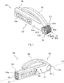
Fig. 1 is a perspective view of a tool in a first embodiment of the invention; -
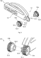
Fig. 2 is a perspective view of a head element of a tool of the first embodiment of the invention; -
Fig. 3 shows an exploded perspective view of the tool of the first embodiment; -
Fig. 4 is a perspective partial view, on a larger scale, of details of the tool ofFig. 3 ; -
Fig. 5 shows a side view of the tool in the first embodiment; -
Fig. 6 is an exploded perspective view of the tool of the first embodiment according to the invention; -
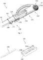
Fig. 7 is a perspective partial view of a tool in a second embodiment of the tool according to the invention; -
Fig. 8 a schematic sectional isometric view of a detail of the second embodiment of the tool according to the invention; -
Fig. 9 is an exploded perspective partial view of a tool in a third embodiment of the invention; -
Fig. 10 is a partial side view of the tool ofFig. 9 ; -
Fig. 11 shows a variant of the tool ofFig. 9 ; -
Fig. 12 is an exploded perspective partial view of a tool in a fourth embodiment of the invention; -
Fig. 13 shows a variant of the tool ofFig. 12 ; -
Fig. 14 is a partial sectional perspective view of a vapour barrier collar in a mounted condition, surrounding an aperture of a roof-penetrating building structure in the form of a roof window; -
Fig. 15 is a partial sectional perspective view, on a larger scale, of the detail XV ofFig. 14 , showing the mounting means in engagement with the groove in the frame of the roof window; and -
Fig. 16 is a schematic side view, on a larger scale, showing the construction of the mounting means of the vapour barrier collar. - In the following, embodiments of a tool according to the invention will be described. The tool may be provided either separately or forming part of a kit including also at least a vapour barrier collar to be used in the installation of a roof window.
- Referring now to
Fig. 14 , a perspective, partial sectional view of a vapour barrier collar generally designated 10 is shown in connection with aroof window 1 having awindow frame 2 mounted in an aperture in a roof structure. Thevapour barrier collar 10 comprises a number of sheet elements of which thebottom sheet element 11 is shown. For example, two side sheet elements, a top sheet element and thebottom sheet element 11 may be provided. Theroof window 1 also comprises asash 3 in which apane 4 is encased. Thewindow frame 2 is built into a roof structure of any suitable configuration, here represented bybattens 7, but may also comprise rafters, underroof, insulation and further details not described. Alining panel 5 is configured to form a transition between thewindow frame 2 and an inner wall of a room of the building in which theroof window 1 is installed, on the interior side of thevapour barrier collar 10. In the example shown, theroof window 1 is substantially rectangular, and thewindow frame 2 comprises four mutually orthogonal frame members; each of these members will be referred to only as "window frame 2". - The
vapour barrier collar 10 is intended to be connected to avapour barrier membrane 8 of an underroof forming part of the overall roof structure, here by atape 9 at aninterior edge 11a of thebottom sheet element 11 of thevapour barrier collar 10. Thevapour barrier collar 10 is, in the example shown, substantially symmetrical about both a longitudinal central axis and a lateral central axis. Due to this symmetry, it is understood that the description applies for all sections of thevapour barrier collar 10 though only one section of thevapour barrier collar 10 is described. - In one example the vapour barrier collar is composed of four
trapezoidal sheet elements 11 welded together to form a vapour barrier collar having the shape of a frustum of a pyramid. It is to be understood that the invention described is equally applicable to a vapour barrier collar having the shape shown in the above-mentionedEP 0 994 991 . Thesheet elements 11 are mutually joined together in joints extending along end edges to form a collar including a coherent rim along first edges of the respective sheet elements. - The material of the
vapour barrier collar 10 is a substantially incompressible plastic material, formed as a film or foil of a suitable plastic material, for instance of polyethylene. Thevapour barrier collar 10 has a thickness of about 0.2 mm and has a low permeability such that the insulation is protected from moisture formed on the warmer inside of the building. - Referring now also to
Figs 15 and 16 , mounting means 12 of thevapour barrier collar 10 are successively introduced into acircumferential groove 21 of thewindow frame 2 by applying a pressure on the mounting means 12 by the aid of an inventive tool to be described below. The configuration of the respective sections of thevapour barrier collar 10 is represented by thebottom sheet element 11, in which a sheet of a suitable foil material is provided with the mounting means 12 at anexterior edge 11b, opposite theinterior edge 11a. The mounting means 12 comprise ananchor element 12a of a suitable material, such as a relatively rigid plastic material, which is fastened to the foil of thebottom sheet element 11 by for instance welding. At a respective end of theanchor element 12a, sealingelements elements vapour barrier collar 10 is brought into connection with thegroove 21 of thewindow frame 2. Typical measurements of thegroove 21 and hence of the height HM are about 12.5 mm. This will also accommodatelining panels 5 made of gypsum or other board materials of standard thickness. - Now referring to
Figs 1 to 6 , a first embodiment of atool 50 according to the present invention for use in the installation, or mounting, of a vapour barrier will be described in further detail. Thetool 50 is thus applicable for use in mounting a vapour barrier of any suitable configuration, for instance in the form of a vapour barrier collar as described above whether formed by 1) four trapezoidal sheet elements, 2) two trapezoidal sheet elements and two rectangular sheet elements as the prior art vapour barrier collar described inEP 0 994 991 , or 3) any other shape. Thetool 50 comprises ahead element 51 including afront end 55 at which insertion means 52 for introducing the mounting means 12 of thevapour barrier collar 10 into thegroove 21 are formed. Thehead element 51 of thetool 50 is furthermore provided with operating means 54 for operating thetool 50 when arranging the mounting means 12 into thegroove 21 of thewindow frame 2. - The
head element 51 of thetool 50 has arear end 59, which in principle could form the rear end of theentire tool 50. A longitudinal direction LX is defined as extending through thefront end 55 and therear end 59. In the embodiment shown, thetool 50 also comprises abody element 60, cf.Fig. 6 , which has a secondrear end 65 opposite thefront end 55 of thehead element 51 of thetool 50. Depending on the dimensions of thehead element 51 and thebody element 60, the overall length of thetool 50 in the embodiment shown, between the secondrear end 65 andfront end 55, may range between 100 and 300 mm to ensure ease of operability of thetool 50 while still being able to be stored conveniently between uses. The length of thehead element 51 between thefront end 55 and therear end 59 is chosen such that the operating means 54 of thetool 50 are oblong so as to serve as a handle in itself by providing a sufficiently comfortable grip on the operating means 54. The total length of thehead element 51 typically amounts to 50 to 100 mm, here about 75 mm. - Further details of the
head element 51 of thetool 50 include aclip 58. The clip may provide a storage option when not in use, for instance to secure the tool onto a piece of clothing. Theclip 58 may also serve as a rest for the installer's index finger. Thehead element 51 of the shown embodiment of thetool 50 furthermore comprises anoblong cavity 56 and anopening 57 towards the ambient in connection with thecavity 56, at therear end 59. Thecavity 56 is able to receive at least partially and retain a correspondingly oblong object, here thebody element 60, and/or an accessory equipment. The dimension of thecavity 56 in a longitudinal direction is at least slightly larger than the dimension of thecavity 56 in a transversal direction. In this particular embodiment, the dimension of thecavity 56 in a longitudinal direction is approximately 1.5 times larger than the dimension of thecavity 56 in a transversal direction. Thebody element 60 is arranged to be inserted in thecavity 56. Thus, the body element needs to have slightly smaller dimensions in order to comfortably fit into thecavity 56. Thecavity 56 is provided withlongitudinal ridges 56a to provide at the same time easy insertion into and a suitable resistance against inadvertent withdrawal from thecavity 56 of the body element, or of accessory equipment to be described below. Thebody element 60 may thus be serving as a handle as it prolongs, or extends, the operating means 54 of thetool 50. Different cross-sectional shapes may be envisaged besides rectangular, for instance square, oval, elliptic or round. Thebody element 60 here comprises a carpenter's pencil with afront portion 60a configured to form a tip of the carpenter's pencil to be sharpened as desired. - The insertion means 52 comprise a roller wheel set 53 including at least one roller wheel for applying a pressure and rolling on the mounting means 12 of the sheet elements, including
bottom sheet element 11 as shown inFig. 14 , of thevapour barrier collar 10 to arrange the mounting means 12 into thegroove 21 of thewindow frame 2 of the roof window. The roller wheel set 53 is connected to the operating means 54 of thehead element 51 at a wheel centre 53.1 at thefront end 55 of thetool 50. In the embodiment shown, twowheels wheels front end 55 has a width and a diameter and are arranged so that a rotation of theroller wheels tool 50 is admitted so that the mounting means 12 are arranged in thegroove 21 by rolling the rolling wheels in the longitudinal direction LX of thetool 50 and along the respective length direction of the individual members of thewindow frame 2. Eachroller wheel roller wheels groove 21 in which the mounting means 12 of thevapour barrier collar 10 are to be arranged. The width WW of eachroller wheel vapour barrier collar 10. Theroller wheel 53; 53a, 53b may have a width-to-diameter ratio of between 1:1 to 1:3, meaning that the width WW and the diameter DW may be equally big, but also that the width cannot be too narrow. If the width is too narrow, the applied pressure during installation may cause perforation in the barrier material. The tworoller wheels front end 55 of thetool 50, substantially corresponding to the total width WT of theroller wheels groove 21 into which the mounting means of the vapour barrier collar is to be inserted. The width of the insertion means 52 at thefront end 55 of thetool 50 generally preferably lies between 10 and 12 mm, depending on the width of thegroove 21. The width of the insertion means 52 should be chosen such that thetool 50 may be moved along thegroove 21 in thewindow frame 2, however without catching against the side walls of thegroove 21. In this first embodiment, the operating means 54 of thehead element 51 of the tool comprises a narrowfront portion 54a having a width substantially corresponding to or slightly smaller than the total width WT, and a widerrear portion 54b. For instance, the width of the widerrear portion 54b may exceed the width of thegroove 21 such that only the narrowfront portion 54a and the insertion means 52 of thetool 50 move within thegroove 21. - Referring now also to
Figs 3 and 4 , theroller wheels roller wheels tool 50 against the surface of thevapour barrier collar 10 aimed at may in principle be chosen. In the following the cog-like structure is referred to as cogs 53.2. The cogs 53.2 are arranged to improve the grip towards the vapour barrier material and subsequently during installation; theroller wheels tool 50 does not push the vapour barrier material in front of the tool (or below thetool 50, in case thetool 50 is rolled backwards). In this way, stack-up of the material is prevented. The movement of thetool 50 in thegroove 21 may in principle be carried out either forwards or backwards in the longitudinal direction LX. The cogs 53.2 may be arranged across at least part of the width of the roller wheel, preferably across at least 80% of the width. The cogs may as shown have a blunt tip. This may ensure that the cog edges do not perforate the vapour barrier material. However, the cogs may be substantially sharp. As best seen inFig. 4 , the cogs 53.2 are shallow. This means that they have a major diameter-to-minor diameter ratio close to 1:1. The shallowness of the cog may ensure that the applied pressure onto theroller wheel 53 during installation does not cause perforations in the vapour barrier material. The cogs may be arranged at an angle relative to the rolling direction across the width of theroller wheel - The two
roller wheels head element 51 and are connected to each other by means of two snap hook legs 53.3 on oneroller wheel 53a interacting with a counterpart receiving aperture 53.4 in theother roller wheel 53b via an opening 51.2 in the protruding front portion 51.1. Theother roller wheel 53b is here provided with a socket portion 53.5 with guiding means for the snap hook legs 53.3 and cooperates with the opening 51.2 in the protruding front portion 51.1 such that a smooth rolling movement is facilitated. Thewheels - As best shown in
Fig. 5 , eachroller wheel head element 51 at the wheel centre 53.1 such that the roller wheels are confined substantially at extensions of the contours of thehead element 51 of thetool 50, i.e. within a straight line continuing from the contour of an under side 51.3 of thehead element 51 and a curved line continuing from the contour of a curved upper side 51.4. Only a portion of theroller wheels vapour barrier collar 10 in use of thetool 50. - While the body element in the form of the carpenter's
pencil 60 in the first embodiment is accommodated directly in thecavity 56 of thehead element 51, a second embodiment shown inFig. 7 comprises anaccessory equipment 161. Elements of the second embodiment having the same or analogous function as elements of the first embodiment carry the same reference numerals to which 100 has been added. Only differences will be described in detail. - The
accessory equipment 161 of the second embodiment is accommodated in the cavity (not visible inFig. 7 ) of thehead element 151 oftool 150. In the position shown inFig. 7 , theaccessory equipment 161 is partially withdrawn from thehead element 151. In its fully inserted position, arear end 169 of theaccessory equipment 161 is substantially flush with therear end 159 of thehead element 151. - Securing means 170 are provided to safely engage the
accessory equipment 161 with thehead element 151 of thetool 150. The securing means 170 comprises ahook element 172 and aconnect element 171. The hook element 162 is arranged at or near therear end 159 of thehead element 151, and theconnect element 171 is arranged at or near arear end 169 of theauxiliary equipment 161 such that thehook element 172 engages theconnect element 171 when theauxiliary equipment 161 is fully inserted into the oblong cavity of thehead element 151. - One example of an accessory equipment of the second embodiment is shown in stylized form in
Fig. 8 . Here, the accessory equipment is in the form of anadapter element 161 having suitable dimensions and outer shape (for instance rounded, even though it is shown having a substantially rectangular cross-section) to engage with thehead element 151. Theadapter element 161 is provided with twocavities cavity 164b closer to arear end 169 of theadapter element 161 is configured to receive a carpenter's pencil of one standard size, for instance a cavity of about 16x7 mm, and theother cavity 164a having suitable dimensions to receive a different, smaller type of pencil, for instance 9x6 mm, as illustrated byalternative body element 160. Theaccessory equipment 161 of this embodiment may also act as an adapter element for receiving other accessory equipment. - Referring now to
Fig. 9 in which an exploded view of atool 250 in a third embodiment is shown. Elements of the third embodiment having the same or analogous function as elements of the first embodiment carry the same reference numerals to which 200 has been added. Only differences will be described in detail. - The
tool 250 is shown with anauxiliary equipment 261 retracted fromhead element 251.Body element 60 is also shown separated from theauxiliary equipment 261. The auxiliary equipment comprises aknife blade 262 retained in aknife holder 263. Theknife blade 262 is configured to be received in theoblong cavity 256 of thehead element 251 as shown inFig. 10 . Theknife holder 263 of theauxiliary equipment 261 is provided with anoblong cavity 266 configured to receive thebody element 60. Theknife blade 262 may for instance be of the kind which is industry standard for exchangeable knife blades. - As in the second embodiment, securing means 270 are provided for securing the
auxiliary equipment 261 to thehead element 251, cf.Fig. 10 in which thehook element 272 engages theconnect element 271 in the position in which theauxiliary equipment 261 is fully inserted into theoblong cavity 256 of thehead element 251. - The
tool 250 thus constitutes a multi-purpose tool, having insertion means 252 on thehead element 251 for use in arranging the vapour barrier collar in the groove in the window frame member, but also a knife tool provided by theauxiliary equipment 261 and configured to be used independently from the insertion means 252. As a matter of safety, the knife tool may in fact not be used at the same time as the insertion means. -
Fig. 11 shows a variant of the tool of the third embodiment. Elements having the same or analogous function as in the third embodiment are denoted by the same reference numerals to which ' has been added. Here, the tool 250' is provided with insertion means 252' of a rounded, fixed shape. Also tool 250' functions as a multi-purpose tool. - An
alternative accessory equipment 361 is shown in the fourth embodiment ofFig. 12 . Elements of the fourth embodiment having the same or analogous function as elements of the first embodiment carry the same reference numerals to which 300 has been added. Only differences will be described in detail. Afront portion 360a of abody element 360 is configured to be connected to thehead element 351, which may be the same as in the above first, second and third embodiments of thetool 350, or slightly different. Operation of thetool 350 according to this embodiment may be carried out as described in the above, i.e. the insertion means 352 at thefront end 355 of thetool 350 are introduced into the groove in the window frame and brought into engagement with thevapour barrier collar 10, for instance by gripping thebody element 360 with theaccessory equipment 361 thus acting as a handle. At arear end 365 of thetool 350 in this embodiment, theaccessory equipment 361 is provided as a wedge-shaped section with aninclined surface 363. By choosing suitable dimensions of the thickness and height of theaccessory equipment 361, for instance 40 to 50 mm by 5 to 15 mm, and a suitable inclination of theinclined surface 363, theaccessory equipment 361 may be used as a tucker, i.e. an assisting tool in the tucking-in of insulation material at the outer circumference of thewindow frame 2 of theroof window 1. This is particularly useful in the case of strips of insulating material to be tucked into narrow spaces surrounding a building component. Theaccessory equipment 361 of thetool 350 of this embodiment may also be used in other fields of application. - The
tool 350 thus constitutes a multi-purpose tool, having insertion means 352 on thehead element 351 for use in arranging the vapour barrier collar in the groove in the window frame member, but also a tucker tool provided by theauxiliary equipment 361 and configured to be used independently from the insertion means 352. Since the tucker tool is located at the opposite end of thetool 350, it may in fact not be used at the same time as the insertion means. -
Fig. 13 shows a variant of the tool of the fourth embodiment. Elements having the same or analogous function as in the fourth embodiment are denoted by the same reference numerals to which ' has been added. Here, the tool 350' is provided with insertion means 352' of a rounded, fixed shape. Also tool 350' functions as a multi-purpose tool. - The tool of any of the above embodiments may be re-used a number of times. Re-use may include installation of further vapour barrier collars, functioning as a holder/extender of a carpenter's pencil, and/or as a receiver or holder/extender of auxiliary equipment. At the end of life, the parts of the tool may be disposed of in dependence on the material chosen, typically comprising hard plastic.
- The invention is not delimited to the embodiments described in the above and shown in the drawings but various modifications and combinations may be carried out without departing from the scope of the claims.
-
- 1
- roof window
- 2
- window frame
21 groove - 3
- sash
- 4
- pane
- 5
- lining panel
- 6
- insulating member
- 7
- battens
- 8
- vapour barrier membrane
- 9
- tape
- 10
- vapour barrier collar
11 sheet element
11a edge (interior)
11b edge (exterior)
12 mounting means
12a anchor element
12b, 12c sealing elements - 50
- tool
- 51
- head element
51.1 protruding front portion
51.2 opening
51.3 under side
51.4 curved upper side - 52
- insertion means
- 53
- roller wheel set
53a first roller wheel
53b second roller wheel
53.1 wheel centre
53.2 cogs
53.3 snap hook leg
53.4 receiving aperture for snap hook leg
53.5 socket portion - 54
- operating means
54a narrow front portion
54b wide rear portion - 55
- front end of head element
- 56
- oblong cavity
56a ridges - 57
- opening
- 58
- clip
- 59
- rear end of head element
- 60
- body element (carpenter's pencil)
60a front portion (tip of carpenter's pencil)
65 second rear end (of body element) - 150
- tool
- 151
- head element
- 152
- insertion means
- 153
- roller wheel set
- 154
- operating means
- 155
- front end of head element
- 159
- rear end of head element
- 160
- alternative body element (smaller carpenter's pencil)
- 161
- auxiliary equipment / adapter element
164a cavity
164b cavity
169 rear end of auxiliary equipment - 170
- securing means
171 connect element
172 hook element - 250
- tool
- 251
- head element
- 252
- insertion means
- 253
- roller wheel set
- 254
- operating means
- 255
- front end
- 256
- oblong cavity
- 259
- rear end of head element
- 261
- auxiliary equipment / knife tool
262 knife blade
263 knife holder
266 oblong cavity
269 rear end of auxiliary equipment - 270
- securing means
271 connect element
272 hook element - 350
- tool
- 351
- head element
- 352
- insertion means
- 353
- roller wheel set
- 354
- operating means
- 355
- front end
- 356
- oblong cavity
- 359
- rear end of head element
- 360
-
body element 360a front portion - 361
- accessory equipment / tucker tool
- 363
- inclined surface
- 365
- rear end
- LX
- longitudinal direction
- HM
- height, mounting means
- DW
- diameter, wheel
- WW
- width, wheel
- WT
- width, total
Claims (16)
- Tool (50) for use in the installation of a vapour barrier collar (10), comprising a head element (51) with a front end (55) and a rear end (59), the head element (51) defining a longitudinal direction (LX) of the tool (50) and comprising operating means (54) for operating the tool and insertion means (52) for introducing mounting means (12) of said vapour barrier collar (10) into a groove (21) of a roof window, said groove being adapted to receive said mounting means, characterised in that said insertion means (52) comprise a roller wheel set (53) including at least one roller wheel (53a, 53b) at the front end (55) of the head element (51) of the tool (50), the roller wheel set (53) having a width (WT) and a diameter (DW) and being arranged so that a rotation of the roller wheel set (53) in the longitudinal direction (LX) of the tool (50) is admitted so that the mounting means (12) of the vapour barrier collar (1) are arranged in the groove (21) by rolling said roller wheel set (53).
- Tool according to claim 1, wherein each roller wheel (53a, 53b) of the roller wheel set (53) is provided with a cog-like outer face, wherein cogs (53.2) are arranged across a substantial part of the width of the roller wheel (53a, 53b).
- Tool according to claim 2, wherein the cogs (53.2) are arranged at an angle at least partially across the width of the roller wheel (53a, 53b), or perpendicular to a linear rolling direction of the roller wheel (53a, 53b) in the longitudinal direction (LX) of the tool (50), the cogs having a pre-defined maximum depth of 0.1 to 5 mm, preferably 1 to 2 mm.
- Tool according to any one of the preceding claims, wherein the roller wheel set (53) comprises two roller wheels (53a, 53b) arranged at a respective side of a protruding front portion (51.1) of the head element (51) and connected to each other by means of at least one snap hook leg (53.3) on one roller wheel (53a) interacting with a counterpart receiving aperture (53.4) in the other roller wheel (53b) via an opening (51.2) in the protruding front portion (51.1), the other roller wheel (53b) preferably comprising a socket portion (53.5) with guiding means for said at least one snap hook leg (53.3) and cooperating with the opening (51.2) in the protruding front portion (51.1).
- Tool according to any one of the preceding claims, wherein each roller wheel (53a, 53b) of the roller wheel set (53) is connected to the head element (51) at a wheel centre (53.1) such that the roller wheel/s is/are confined substantially at extensions of the contours (51.3, 51.4) of the head element (51) of the tool (50).
- Tool according to any one of the preceding claims, wherein each roller wheel (53a, 53b) of the roller wheel set (53) has a width-to-diameter ratio of about 1:1, 1:2 but not more than 1:3.
- Tool according to any one of the preceding claims, wherein said operating means (54) of the head element (51) comprise an oblong cavity (56) and an opening (57) towards the ambient at the rear end (59) of the head element (51) in connection with said cavity (56), said cavity (56) being able to receive at least partially and retain an oblong body element (60; 160; 260; 360).
- Tool according to claim 7, further comprising an accessory equipment (161; 261; 361) arranged in connection with the head element (151; 251; 351) of the tool (150; 250; 350) and optionally the body element (60; 160; 260; 360).
- Tool according to claim 8, wherein said accessory equipment comprises an adapter element (161) having at least two cavities (164a, 164b) of mutually different cross-sectional dimensions in the longitudinal direction (LX) of the tool (150).
- Tool according to claim 8, wherein said accessory equipment (261) comprises a knife blade (262) retained in a knife holder (263).
- Tool according to claim 10, wherein the knife blade (262) is configured to be received in the oblong cavity (256) of the head element (251), and wherein the knife holder (263) of the auxiliary equipment (261) is provided with an oblong cavity (266) configured to receive a body element (60).
- Tool according to any one of claims 8 to 11, wherein said tool (150; 250) comprises securing means (170; 270) for securing said auxiliary equipment (161; 261) to said head element (151; 251).
- Tool according to claim 12, wherein said securing means (170; 270) comprises a hook element (172; 272) and a connect element (171; 271), wherein the hook element (172) is arranged at or near the rear end (159; 259) of the head element (151; 251), and wherein the connect element (171; 271) is arranged at or near a rear end (169; 269) of the auxiliary equipment (161; 261) such that the hook element (172; 272) engages the connect element (171; 271) when the auxiliary equipment (161; 261) is fully inserted into the oblong cavity (256) of the head element (151; 251).
- Tool according to clam 8, wherein said accessory equipment (361) comprises a wedge-shaped section including an inclined surface (163), configured to act as a tucker for insulation material.
- Kit comprising a tool (50) according to any one of claims 1 to 14 and a vapour barrier collar (10) including mounting means (12).
- Kit according to claim 15, further comprising at least one accessory equipment (161; 261; 361).
Applications Claiming Priority (1)
| Application Number | Priority Date | Filing Date | Title |
|---|---|---|---|
| DKPA202070246 | 2020-04-22 |
Publications (2)
| Publication Number | Publication Date |
|---|---|
| EP3900879A1 true EP3900879A1 (en) | 2021-10-27 |
| EP3900879B1 EP3900879B1 (en) | 2024-05-01 |
Family
ID=75625485
Family Applications (1)
| Application Number | Title | Priority Date | Filing Date |
|---|---|---|---|
| EP21169645.5A Active EP3900879B1 (en) | 2020-04-22 | 2021-04-21 | Kit comprising a tool and a vapour barrier collar |
Country Status (3)
| Country | Link |
|---|---|
| EP (1) | EP3900879B1 (en) |
| DE (3) | DE202021102160U1 (en) |
| PL (1) | PL3900879T3 (en) |
Citations (9)
| Publication number | Priority date | Publication date | Assignee | Title |
|---|---|---|---|---|
| US4578851A (en) * | 1982-07-13 | 1986-04-01 | Song In W | Tool |
| US4790059A (en) * | 1988-01-12 | 1988-12-13 | Killpack Ronald E | Carpet laying tool and method of use |
| US5749434A (en) * | 1994-04-11 | 1998-05-12 | Safety Equipment Inc. | Roof edge protection system |
| US5868900A (en) * | 1994-01-26 | 1999-02-09 | Roller International Asa | Tool for fixation of cable or line |
| EP0994991A1 (en) | 1997-07-09 | 2000-04-26 | VELUX Industri A/S | A skylight window with attachment collar for a vapour barrier membrane |
| US20050034309A1 (en) * | 2002-01-07 | 2005-02-17 | Richard Arent | Utility knife with compression wheel |
| US20070033740A1 (en) * | 2005-08-09 | 2007-02-15 | Howard Dehner | Combination tool for cutting and rolling |
| EP2711480A2 (en) * | 2009-03-17 | 2014-03-26 | VKR Holding A/S | A tool for use in mounting a vapour barrier collar and a method for mounting a vapour barrier collar |
| FR3058350A1 (en) * | 2016-11-08 | 2018-05-11 | Daniel Jean Maurice Chouzy | CUTTER WITH A ROULETTE TO CONTROL CUTTING PRESSURE |
Family Cites Families (2)
| Publication number | Priority date | Publication date | Assignee | Title |
|---|---|---|---|---|
| US8245753B2 (en) * | 2006-01-05 | 2012-08-21 | Haemerle Richard R | Hand tools for applying masking tape and the like to various surfaces |
| CA2646610A1 (en) * | 2007-12-19 | 2009-06-19 | Ed Vaes | Wheels for knives and screening tools |
-
2021
- 2021-04-21 EP EP21169645.5A patent/EP3900879B1/en active Active
- 2021-04-21 PL PL21169645.5T patent/PL3900879T3/en unknown
- 2021-04-22 DE DE202021102160.8U patent/DE202021102160U1/en active Active
- 2021-04-22 DE DE202021102158.6U patent/DE202021102158U1/en active Active
- 2021-04-22 DE DE202021102163.2U patent/DE202021102163U1/en active Active
Patent Citations (11)
| Publication number | Priority date | Publication date | Assignee | Title |
|---|---|---|---|---|
| US4578851A (en) * | 1982-07-13 | 1986-04-01 | Song In W | Tool |
| US4790059A (en) * | 1988-01-12 | 1988-12-13 | Killpack Ronald E | Carpet laying tool and method of use |
| US5868900A (en) * | 1994-01-26 | 1999-02-09 | Roller International Asa | Tool for fixation of cable or line |
| US5749434A (en) * | 1994-04-11 | 1998-05-12 | Safety Equipment Inc. | Roof edge protection system |
| EP0994991A1 (en) | 1997-07-09 | 2000-04-26 | VELUX Industri A/S | A skylight window with attachment collar for a vapour barrier membrane |
| US20050034309A1 (en) * | 2002-01-07 | 2005-02-17 | Richard Arent | Utility knife with compression wheel |
| US20070033740A1 (en) * | 2005-08-09 | 2007-02-15 | Howard Dehner | Combination tool for cutting and rolling |
| EP2711480A2 (en) * | 2009-03-17 | 2014-03-26 | VKR Holding A/S | A tool for use in mounting a vapour barrier collar and a method for mounting a vapour barrier collar |
| EP2243893B1 (en) | 2009-03-17 | 2016-08-24 | VKR Holding A/S | Vapour barrier collar, method for producing a vapour barrier collar |
| EP2711480B1 (en) | 2009-03-17 | 2020-01-22 | VKR Holding A/S | A tool for use in mounting a vapour barrier collar and a method for mounting a vapour barrier collar |
| FR3058350A1 (en) * | 2016-11-08 | 2018-05-11 | Daniel Jean Maurice Chouzy | CUTTER WITH A ROULETTE TO CONTROL CUTTING PRESSURE |
Also Published As
| Publication number | Publication date |
|---|---|
| PL3900879T3 (en) | 2024-07-22 |
| EP3900879B1 (en) | 2024-05-01 |
| DE202021102160U1 (en) | 2021-08-16 |
| DE202021102158U1 (en) | 2021-08-16 |
| DE202021102163U1 (en) | 2021-08-16 |
Similar Documents
| Publication | Publication Date | Title |
|---|---|---|
| US12257687B2 (en) | Folding tool | |
| US4408396A (en) | Trim knife | |
| US4884342A (en) | Utility knife | |
| EP3900879B1 (en) | Kit comprising a tool and a vapour barrier collar | |
| KR101006644B1 (en) | Marking Tape Mounting | |
| GB2094677A (en) | Wiper device | |
| CA2484055A1 (en) | Cutting mat | |
| CN101839043B (en) | Mounting ring for vapor barrier, manufacturing method, mounting tool and mounting method thereof | |
| WO1996014189A1 (en) | Combination tool for wallboard | |
| WO1997047548A1 (en) | Hook assembly for use on masking device | |
| JP5794851B2 (en) | Cutting blade | |
| US12410623B1 (en) | Putty scraper | |
| CN223201380U (en) | Just, tear formula adhesive tape roll | |
| KR200397617Y1 (en) | Tape cutting | |
| KR100893724B1 (en) | Gypsum Board Joint | |
| JPH08309045A (en) | Replacement blade for thinning razor and thinning razor | |
| WO2021214005A1 (en) | A drywall panel cutter | |
| JPH0639649Y2 (en) | Tarpaulin cutting device | |
| JP2003019373A (en) | Insulated cladding cutting cutter | |
| WO2006118002A1 (en) | Bit holder device | |
| CA2534447C (en) | Hand-held carpenters tool | |
| JP4670117B2 (en) | Toilet paper holder | |
| CA1101653A (en) | Cutting tool and blade holder for replaceable blades | |
| JP2005073998A (en) | Sliding-screen paper cutter | |
| JPH10328441A (en) | Synthetic resin corrugated tube cutter |
Legal Events
| Date | Code | Title | Description |
|---|---|---|---|
| PUAI | Public reference made under article 153(3) epc to a published international application that has entered the european phase |
Free format text: ORIGINAL CODE: 0009012 |
|
| STAA | Information on the status of an ep patent application or granted ep patent |
Free format text: STATUS: THE APPLICATION HAS BEEN PUBLISHED |
|
| AK | Designated contracting states |
Kind code of ref document: A1 Designated state(s): AL AT BE BG CH CY CZ DE DK EE ES FI FR GB GR HR HU IE IS IT LI LT LU LV MC MK MT NL NO PL PT RO RS SE SI SK SM TR |
|
| B565 | Issuance of search results under rule 164(2) epc |
Effective date: 20210903 |
|
| STAA | Information on the status of an ep patent application or granted ep patent |
Free format text: STATUS: REQUEST FOR EXAMINATION WAS MADE |
|
| 17P | Request for examination filed |
Effective date: 20220427 |
|
| RBV | Designated contracting states (corrected) |
Designated state(s): AL AT BE BG CH CY CZ DE DK EE ES FI FR GB GR HR HU IE IS IT LI LT LU LV MC MK MT NL NO PL PT RO RS SE SI SK SM TR |
|
| STAA | Information on the status of an ep patent application or granted ep patent |
Free format text: STATUS: EXAMINATION IS IN PROGRESS |
|
| 17Q | First examination report despatched |
Effective date: 20230519 |
|
| RIC1 | Information provided on ipc code assigned before grant |
Ipc: E04D 13/03 20060101ALI20231122BHEP Ipc: E04D 12/00 20060101ALI20231122BHEP Ipc: B26B 29/02 20060101ALI20231122BHEP Ipc: B26B 11/00 20060101ALI20231122BHEP Ipc: E04D 15/00 20060101ALI20231122BHEP Ipc: E04D 13/00 20060101ALI20231122BHEP Ipc: B26B 5/00 20060101ALI20231122BHEP Ipc: B25B 27/00 20060101AFI20231122BHEP |
|
| GRAP | Despatch of communication of intention to grant a patent |
Free format text: ORIGINAL CODE: EPIDOSNIGR1 |
|
| STAA | Information on the status of an ep patent application or granted ep patent |
Free format text: STATUS: GRANT OF PATENT IS INTENDED |
|
| INTG | Intention to grant announced |
Effective date: 20240116 |
|
| GRAS | Grant fee paid |
Free format text: ORIGINAL CODE: EPIDOSNIGR3 |
|
| GRAA | (expected) grant |
Free format text: ORIGINAL CODE: 0009210 |
|
| STAA | Information on the status of an ep patent application or granted ep patent |
Free format text: STATUS: THE PATENT HAS BEEN GRANTED |
|
| AK | Designated contracting states |
Kind code of ref document: B1 Designated state(s): AL AT BE BG CH CY CZ DE DK EE ES FI FR GB GR HR HU IE IS IT LI LT LU LV MC MK MT NL NO PL PT RO RS SE SI SK SM TR |
|
| REG | Reference to a national code |
Ref country code: GB Ref legal event code: FG4D |
|
| REG | Reference to a national code |
Ref country code: CH Ref legal event code: EP |
|
| REG | Reference to a national code |
Ref country code: DE Ref legal event code: R096 Ref document number: 602021012501 Country of ref document: DE |
|
| REG | Reference to a national code |
Ref country code: IE Ref legal event code: FG4D |
|
| REG | Reference to a national code |
Ref country code: LT Ref legal event code: MG9D |
|
| REG | Reference to a national code |
Ref country code: NL Ref legal event code: MP Effective date: 20240501 |
|
| PG25 | Lapsed in a contracting state [announced via postgrant information from national office to epo] |
Ref country code: IS Free format text: LAPSE BECAUSE OF FAILURE TO SUBMIT A TRANSLATION OF THE DESCRIPTION OR TO PAY THE FEE WITHIN THE PRESCRIBED TIME-LIMIT Effective date: 20240901 |
|
| PG25 | Lapsed in a contracting state [announced via postgrant information from national office to epo] |
Ref country code: BG Free format text: LAPSE BECAUSE OF FAILURE TO SUBMIT A TRANSLATION OF THE DESCRIPTION OR TO PAY THE FEE WITHIN THE PRESCRIBED TIME-LIMIT Effective date: 20240501 |
|
| PG25 | Lapsed in a contracting state [announced via postgrant information from national office to epo] |
Ref country code: FI Free format text: LAPSE BECAUSE OF FAILURE TO SUBMIT A TRANSLATION OF THE DESCRIPTION OR TO PAY THE FEE WITHIN THE PRESCRIBED TIME-LIMIT Effective date: 20240501 Ref country code: HR Free format text: LAPSE BECAUSE OF FAILURE TO SUBMIT A TRANSLATION OF THE DESCRIPTION OR TO PAY THE FEE WITHIN THE PRESCRIBED TIME-LIMIT Effective date: 20240501 |
|
| PG25 | Lapsed in a contracting state [announced via postgrant information from national office to epo] |
Ref country code: GR Free format text: LAPSE BECAUSE OF FAILURE TO SUBMIT A TRANSLATION OF THE DESCRIPTION OR TO PAY THE FEE WITHIN THE PRESCRIBED TIME-LIMIT Effective date: 20240802 |
|
| PG25 | Lapsed in a contracting state [announced via postgrant information from national office to epo] |
Ref country code: PT Free format text: LAPSE BECAUSE OF FAILURE TO SUBMIT A TRANSLATION OF THE DESCRIPTION OR TO PAY THE FEE WITHIN THE PRESCRIBED TIME-LIMIT Effective date: 20240902 |
|
| REG | Reference to a national code |
Ref country code: AT Ref legal event code: MK05 Ref document number: 1681706 Country of ref document: AT Kind code of ref document: T Effective date: 20240501 |
|
| PG25 | Lapsed in a contracting state [announced via postgrant information from national office to epo] |
Ref country code: NL Free format text: LAPSE BECAUSE OF FAILURE TO SUBMIT A TRANSLATION OF THE DESCRIPTION OR TO PAY THE FEE WITHIN THE PRESCRIBED TIME-LIMIT Effective date: 20240501 |
|
| PG25 | Lapsed in a contracting state [announced via postgrant information from national office to epo] |
Ref country code: ES Free format text: LAPSE BECAUSE OF FAILURE TO SUBMIT A TRANSLATION OF THE DESCRIPTION OR TO PAY THE FEE WITHIN THE PRESCRIBED TIME-LIMIT Effective date: 20240501 |
|
| PG25 | Lapsed in a contracting state [announced via postgrant information from national office to epo] |
Ref country code: AT Free format text: LAPSE BECAUSE OF FAILURE TO SUBMIT A TRANSLATION OF THE DESCRIPTION OR TO PAY THE FEE WITHIN THE PRESCRIBED TIME-LIMIT Effective date: 20240501 |
|
| PG25 | Lapsed in a contracting state [announced via postgrant information from national office to epo] |
Ref country code: LV Free format text: LAPSE BECAUSE OF FAILURE TO SUBMIT A TRANSLATION OF THE DESCRIPTION OR TO PAY THE FEE WITHIN THE PRESCRIBED TIME-LIMIT Effective date: 20240501 |
|
| PG25 | Lapsed in a contracting state [announced via postgrant information from national office to epo] |
Ref country code: PT Free format text: LAPSE BECAUSE OF FAILURE TO SUBMIT A TRANSLATION OF THE DESCRIPTION OR TO PAY THE FEE WITHIN THE PRESCRIBED TIME-LIMIT Effective date: 20240902 Ref country code: NO Free format text: LAPSE BECAUSE OF FAILURE TO SUBMIT A TRANSLATION OF THE DESCRIPTION OR TO PAY THE FEE WITHIN THE PRESCRIBED TIME-LIMIT Effective date: 20240801 Ref country code: NL Free format text: LAPSE BECAUSE OF FAILURE TO SUBMIT A TRANSLATION OF THE DESCRIPTION OR TO PAY THE FEE WITHIN THE PRESCRIBED TIME-LIMIT Effective date: 20240501 Ref country code: LV Free format text: LAPSE BECAUSE OF FAILURE TO SUBMIT A TRANSLATION OF THE DESCRIPTION OR TO PAY THE FEE WITHIN THE PRESCRIBED TIME-LIMIT Effective date: 20240501 Ref country code: IS Free format text: LAPSE BECAUSE OF FAILURE TO SUBMIT A TRANSLATION OF THE DESCRIPTION OR TO PAY THE FEE WITHIN THE PRESCRIBED TIME-LIMIT Effective date: 20240901 Ref country code: HR Free format text: LAPSE BECAUSE OF FAILURE TO SUBMIT A TRANSLATION OF THE DESCRIPTION OR TO PAY THE FEE WITHIN THE PRESCRIBED TIME-LIMIT Effective date: 20240501 Ref country code: GR Free format text: LAPSE BECAUSE OF FAILURE TO SUBMIT A TRANSLATION OF THE DESCRIPTION OR TO PAY THE FEE WITHIN THE PRESCRIBED TIME-LIMIT Effective date: 20240802 Ref country code: FI Free format text: LAPSE BECAUSE OF FAILURE TO SUBMIT A TRANSLATION OF THE DESCRIPTION OR TO PAY THE FEE WITHIN THE PRESCRIBED TIME-LIMIT Effective date: 20240501 Ref country code: ES Free format text: LAPSE BECAUSE OF FAILURE TO SUBMIT A TRANSLATION OF THE DESCRIPTION OR TO PAY THE FEE WITHIN THE PRESCRIBED TIME-LIMIT Effective date: 20240501 Ref country code: BG Free format text: LAPSE BECAUSE OF FAILURE TO SUBMIT A TRANSLATION OF THE DESCRIPTION OR TO PAY THE FEE WITHIN THE PRESCRIBED TIME-LIMIT Effective date: 20240501 Ref country code: AT Free format text: LAPSE BECAUSE OF FAILURE TO SUBMIT A TRANSLATION OF THE DESCRIPTION OR TO PAY THE FEE WITHIN THE PRESCRIBED TIME-LIMIT Effective date: 20240501 Ref country code: RS Free format text: LAPSE BECAUSE OF FAILURE TO SUBMIT A TRANSLATION OF THE DESCRIPTION OR TO PAY THE FEE WITHIN THE PRESCRIBED TIME-LIMIT Effective date: 20240801 |
|
| PG25 | Lapsed in a contracting state [announced via postgrant information from national office to epo] |
Ref country code: DK Free format text: LAPSE BECAUSE OF FAILURE TO SUBMIT A TRANSLATION OF THE DESCRIPTION OR TO PAY THE FEE WITHIN THE PRESCRIBED TIME-LIMIT Effective date: 20240501 |
|
| PG25 | Lapsed in a contracting state [announced via postgrant information from national office to epo] |
Ref country code: EE Free format text: LAPSE BECAUSE OF FAILURE TO SUBMIT A TRANSLATION OF THE DESCRIPTION OR TO PAY THE FEE WITHIN THE PRESCRIBED TIME-LIMIT Effective date: 20240501 |
|
| PG25 | Lapsed in a contracting state [announced via postgrant information from national office to epo] |
Ref country code: CZ Free format text: LAPSE BECAUSE OF FAILURE TO SUBMIT A TRANSLATION OF THE DESCRIPTION OR TO PAY THE FEE WITHIN THE PRESCRIBED TIME-LIMIT Effective date: 20240501 |
|
| PG25 | Lapsed in a contracting state [announced via postgrant information from national office to epo] |
Ref country code: RO Free format text: LAPSE BECAUSE OF FAILURE TO SUBMIT A TRANSLATION OF THE DESCRIPTION OR TO PAY THE FEE WITHIN THE PRESCRIBED TIME-LIMIT Effective date: 20240501 Ref country code: SK Free format text: LAPSE BECAUSE OF FAILURE TO SUBMIT A TRANSLATION OF THE DESCRIPTION OR TO PAY THE FEE WITHIN THE PRESCRIBED TIME-LIMIT Effective date: 20240501 |
|
| PG25 | Lapsed in a contracting state [announced via postgrant information from national office to epo] |
Ref country code: SM Free format text: LAPSE BECAUSE OF FAILURE TO SUBMIT A TRANSLATION OF THE DESCRIPTION OR TO PAY THE FEE WITHIN THE PRESCRIBED TIME-LIMIT Effective date: 20240501 |
|
| PG25 | Lapsed in a contracting state [announced via postgrant information from national office to epo] |
Ref country code: SM Free format text: LAPSE BECAUSE OF FAILURE TO SUBMIT A TRANSLATION OF THE DESCRIPTION OR TO PAY THE FEE WITHIN THE PRESCRIBED TIME-LIMIT Effective date: 20240501 Ref country code: SK Free format text: LAPSE BECAUSE OF FAILURE TO SUBMIT A TRANSLATION OF THE DESCRIPTION OR TO PAY THE FEE WITHIN THE PRESCRIBED TIME-LIMIT Effective date: 20240501 Ref country code: RO Free format text: LAPSE BECAUSE OF FAILURE TO SUBMIT A TRANSLATION OF THE DESCRIPTION OR TO PAY THE FEE WITHIN THE PRESCRIBED TIME-LIMIT Effective date: 20240501 Ref country code: EE Free format text: LAPSE BECAUSE OF FAILURE TO SUBMIT A TRANSLATION OF THE DESCRIPTION OR TO PAY THE FEE WITHIN THE PRESCRIBED TIME-LIMIT Effective date: 20240501 Ref country code: DK Free format text: LAPSE BECAUSE OF FAILURE TO SUBMIT A TRANSLATION OF THE DESCRIPTION OR TO PAY THE FEE WITHIN THE PRESCRIBED TIME-LIMIT Effective date: 20240501 Ref country code: CZ Free format text: LAPSE BECAUSE OF FAILURE TO SUBMIT A TRANSLATION OF THE DESCRIPTION OR TO PAY THE FEE WITHIN THE PRESCRIBED TIME-LIMIT Effective date: 20240501 |
|
| REG | Reference to a national code |
Ref country code: DE Ref legal event code: R097 Ref document number: 602021012501 Country of ref document: DE |
|
| PG25 | Lapsed in a contracting state [announced via postgrant information from national office to epo] |
Ref country code: IT Free format text: LAPSE BECAUSE OF FAILURE TO SUBMIT A TRANSLATION OF THE DESCRIPTION OR TO PAY THE FEE WITHIN THE PRESCRIBED TIME-LIMIT Effective date: 20240501 |
|
| PLBE | No opposition filed within time limit |
Free format text: ORIGINAL CODE: 0009261 |
|
| STAA | Information on the status of an ep patent application or granted ep patent |
Free format text: STATUS: NO OPPOSITION FILED WITHIN TIME LIMIT |
|
| 26N | No opposition filed |
Effective date: 20250204 |
|
| PG25 | Lapsed in a contracting state [announced via postgrant information from national office to epo] |
Ref country code: SI Free format text: LAPSE BECAUSE OF FAILURE TO SUBMIT A TRANSLATION OF THE DESCRIPTION OR TO PAY THE FEE WITHIN THE PRESCRIBED TIME-LIMIT Effective date: 20240501 |
|
| PGFP | Annual fee paid to national office [announced via postgrant information from national office to epo] |
Ref country code: DE Payment date: 20250305 Year of fee payment: 5 |
|
| PG25 | Lapsed in a contracting state [announced via postgrant information from national office to epo] |
Ref country code: SE Free format text: LAPSE BECAUSE OF FAILURE TO SUBMIT A TRANSLATION OF THE DESCRIPTION OR TO PAY THE FEE WITHIN THE PRESCRIBED TIME-LIMIT Effective date: 20240501 |
|
| REG | Reference to a national code |
Ref country code: CH Ref legal event code: H13 Free format text: ST27 STATUS EVENT CODE: U-0-0-H10-H13 (AS PROVIDED BY THE NATIONAL OFFICE) Effective date: 20251125 |
|
| PG25 | Lapsed in a contracting state [announced via postgrant information from national office to epo] |
Ref country code: LU Free format text: LAPSE BECAUSE OF NON-PAYMENT OF DUE FEES Effective date: 20250421 |
|
| PG25 | Lapsed in a contracting state [announced via postgrant information from national office to epo] |
Ref country code: MC Free format text: LAPSE BECAUSE OF FAILURE TO SUBMIT A TRANSLATION OF THE DESCRIPTION OR TO PAY THE FEE WITHIN THE PRESCRIBED TIME-LIMIT Effective date: 20240501 |
|
| REG | Reference to a national code |
Ref country code: BE Ref legal event code: MM Effective date: 20250430 |
|
| PG25 | Lapsed in a contracting state [announced via postgrant information from national office to epo] |
Ref country code: BE Free format text: LAPSE BECAUSE OF NON-PAYMENT OF DUE FEES Effective date: 20250430 |
|
| PG25 | Lapsed in a contracting state [announced via postgrant information from national office to epo] |
Ref country code: CH Free format text: LAPSE BECAUSE OF NON-PAYMENT OF DUE FEES Effective date: 20250430 |
|
| PGFP | Annual fee paid to national office [announced via postgrant information from national office to epo] |
Ref country code: GB Payment date: 20260312 Year of fee payment: 6 |
|
| PG25 | Lapsed in a contracting state [announced via postgrant information from national office to epo] |
Ref country code: IE Free format text: LAPSE BECAUSE OF NON-PAYMENT OF DUE FEES Effective date: 20250421 |
|
| PGFP | Annual fee paid to national office [announced via postgrant information from national office to epo] |
Ref country code: FR Payment date: 20260309 Year of fee payment: 6 |
|
| PGFP | Annual fee paid to national office [announced via postgrant information from national office to epo] |
Ref country code: PL Payment date: 20260313 Year of fee payment: 6 |