EP3900801A1 - System and method for positioning vehicles of an amusement park attraction - Google Patents
System and method for positioning vehicles of an amusement park attraction Download PDFInfo
- Publication number
- EP3900801A1 EP3900801A1 EP21162694.0A EP21162694A EP3900801A1 EP 3900801 A1 EP3900801 A1 EP 3900801A1 EP 21162694 A EP21162694 A EP 21162694A EP 3900801 A1 EP3900801 A1 EP 3900801A1
- Authority
- EP
- European Patent Office
- Prior art keywords
- vehicle
- vehicles
- arm
- arms
- bogie system
- Prior art date
- Legal status (The legal status is an assumption and is not a legal conclusion. Google has not performed a legal analysis and makes no representation as to the accuracy of the status listed.)
- Granted
Links
Images





Classifications
-
- A—HUMAN NECESSITIES
- A63—SPORTS; GAMES; AMUSEMENTS
- A63G—MERRY-GO-ROUNDS; SWINGS; ROCKING-HORSES; CHUTES; SWITCHBACKS; SIMILAR DEVICES FOR PUBLIC AMUSEMENT
- A63G21/00—Chutes; Helter-skelters
- A63G21/06—Chutes; Helter-skelters with passing arrangements for cars
-
- A—HUMAN NECESSITIES
- A63—SPORTS; GAMES; AMUSEMENTS
- A63G—MERRY-GO-ROUNDS; SWINGS; ROCKING-HORSES; CHUTES; SWITCHBACKS; SIMILAR DEVICES FOR PUBLIC AMUSEMENT
- A63G7/00—Up-and-down hill tracks; Switchbacks
Definitions
- the vehicles 12 are configured to rotate about a guide axis 22 in a first rotation direction 24 (e.g., clockwise with respect to FIG. 1 ) and a second rotation direction 26 (e.g., counter-clockwise with respect to FIG. 1 ).
- the guide 14 may rotate about the guide axis 22 in the first rotation direction 24 and the second rotation direction 26.
- rotation of the vehicles 12 and/or the guide 14 about the guide axis 22 may enable adjustment of the position of the vehicles 12 relative to one another, thereby producing the illusion of one vehicle 12 moving ahead of another vehicle 12 in a race.
- the illustrated embodiment includes three vehicles 12 positioned about the guide 14, in other embodiments there may be 1, 2, 4, 5, 6, 7, 8, 9, 10 or any suitable number of vehicles 12.
- a method for controlling an amusement ride with an automation controller and actuators comprising: directing a plurality of vehicles in an operation direction along a track using a shared bogie system and a motor actuator; rotating one or more of the vehicles of the plurality of vehicles about a guide axis with a rotation actuator to adjust a position of the one or more vehicles of the plurality of vehicles with respect to the remaining vehicles of the plurality of vehicles; and moving one or more of the vehicles radially along a length of an arm.
Landscapes
- Motorcycle And Bicycle Frame (AREA)
- Platform Screen Doors And Railroad Systems (AREA)
- Toys (AREA)
- Automobile Manufacture Line, Endless Track Vehicle, Trailer (AREA)
- Intermediate Stations On Conveyors (AREA)
- Transmission Devices (AREA)
- Handcart (AREA)
Abstract
Description
- This application claims the benefit of
U.S. Provisional Application No. 62/141,086 - The present disclosure relates generally to the field of amusement parks. More specifically, embodiments of the present disclosure relate to systems and methods utilized to provide amusement park experiences.
- This section is intended to introduce the reader to various aspects of art that may be related to various aspects of the present techniques, which are described and/or claimed below. This discussion is believed to be helpful in providing the reader with background information to facilitate a better understanding of the various aspects of the present disclosure. Accordingly, it should be understood that these statements are to be read in this light, and not as admissions of prior art.
- Amusement parks often include attractions that incorporate simulated competitive circumstances between the attraction participants. For example, the attractions may have cars or trains in which riders race against one another along a path (e.g., dueling coasters, go carts). Incorporating the competitive circumstances may provide an additional entertainment value to the riders, as well as increase variety for riders utilizing the attraction multiple times. However, traditional systems may include several track sections to provide the simulated competitive circumstances, thereby increasing the cost and complexity of the attraction. It is now recognized that it is desirable to provide improved systems and methods for simulated racing attractions that provide excitement for riders.
- Certain embodiments commensurate in scope with the originally claimed subject matter are discussed below. These embodiments are not intended to limit the scope of the disclosure. Indeed, the present disclosure may encompass a variety of forms that may be similar to or different from the embodiments set forth below.
- In accordance with one embodiment, an apparatus for an amusement park includes a bogie system positioned on a track. The bogie system directs motion along the track. The apparatus also includes an arm extending radially outward from the bogie system. The arm is rotatably coupled to a body of the bogie system. Furthermore, the apparatus includes a vehicle positioned on the arm. The bogie system is configured to move in an operation direction along the track and the vehicle is configured to rotate about the bogie system to change a position of the vehicle with respect to the bogie system.
- In accordance with another embodiment, a system includes a bogie system positioned on a track, where the bogie system is configured to move along the track, a plurality of arms extending radially outward from the bogie system, where each of the plurality of arms is rotatably coupled to a body of the bogie system, and a plurality of vehicles, where each vehicle of the plurality of vehicles is positioned on a corresponding arm of the plurality of arms, and where the plurality of vehicles are positioned at different locations from one another with respect to the bogie system.
- In accordance with another embodiment, a method for controlling an amusement ride with an automation controller and actuators includes directing a plurality of vehicles in an operation direction along a track using a shared bogie system and a motor actuator, and rotating one or more of the vehicles of the plurality of vehicles about a guide axis with a rotation actuator to adjust a position of the one or more vehicles of the plurality of vehicles with respect to the remaining vehicles of the plurality of vehicles.
- These and other features, aspects, and advantages of the present disclosure will become better understood when the following detailed description is read with reference to the accompanying drawings in which like characters represent like parts throughout the drawings, wherein:
-
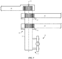
FIG. 1 is a top view of an embodiment of a racer having three vehicles positioned about a guide, in accordance with an aspect of the present disclosure; -
FIG. 2 is a top view of an embodiment of a racer having two vehicles positioned about a guide, in accordance with an aspect of the present disclosure; -
FIG. 3 is a top view of an embodiment of a racer having one vehicle positioned about a guide, in accordance with an aspect of the present disclosure; -
FIG. 4 is a cross-sectional elevation view of an embodiment of a motion system of the racer ofFIG. 1 , in accordance with an aspect of the present disclosure; -
FIG. 5 is a cross-sectional elevation view of an embodiment of a bogie system of a racer, in accordance with an aspect of the present disclosure; -
FIG. 6 is a top view of an embodiment of a racer having one or more arms that include a dogleg or bend, in accordance with an aspect of the present disclosure; -
FIG. 7 is a cross-sectional elevation view of an embodiment of a vehicle coupling system of the racer ofFIG. 1 , in accordance with an aspect of the present disclosure; -
FIG. 8 is a cross-sectional side view of another embodiment of the vehicle coupling system ofFIG. 6 that utilizes an adjustable swash plate and rollers, in accordance with an aspect of the present disclosure; -
FIG. 9 is a schematic of another embodiment of the vehicle coupling system ofFIG. 6 that utilizes multiple adjustable swash plates that include rotatable plates, in accordance with an aspect of the present disclosure; -
FIG. 10 is a top view of an embodiment of the racer ofFIG. 1 , in which a first vehicle is in a first place position, a second vehicle is in a second place position, and a third vehicle is in a third place position, in accordance with an aspect of the present disclosure; -
FIG. 11 is a top view of the racer ofFIG. 10 , in which the first vehicle is in the first place position, the second vehicle is in the third place position, and the third vehicle is in the second place position, in accordance with an aspect of the present disclosure; -
FIG. 12 is a top view of an embodiment of the racer ofFIG. 1 , in which a track includes a curved section, in accordance with an aspect of the present disclosure; -
FIG. 13 is a top view of an embodiment of an attachment mechanism coupling a first guide to a second guide, in accordance with an aspect of the present disclosure; and -
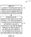
FIG. 14 is a flowchart of an embodiment of a method for controlling the position of the vehicles of the racer ofFIG. 1 , in accordance with an aspect of the present disclosure. - One or more specific embodiments of the present disclosure will be described below. In an effort to provide a concise description of these embodiments, all features of an actual implementation may not be described in the specification. It should be appreciated that in the development of any such actual implementation, as in any engineering or design project, numerous implementation-specific decisions must be made to achieve the developers' specific goals, such as compliance with system-related and business-related constraints, which may vary from one implementation to another. Moreover, it should be appreciated that such a development effort might be complex and time consuming, but would nevertheless be a routine undertaking of design, fabrication, and manufacture for those of ordinary skill having the benefit of this disclosure.
- Attractions at amusement parks that involve competitive circumstances (e.g., racing between riders) may be limited by the physical constraints of the footprint of the attraction and by the amount of control over the ride experience. For example, ride vehicles (e.g., go carts) on a multi-lane track may interact with each other but their interactions are typically based on individual riders and the nature of the experience will thus be limited (e.g., the vehicles are typically configured to run relatively slow). Some racing attractions include several track sections (e.g., roller coaster tracks) with attached ride vehicles to provide more centralized control of the ride experience. These tracks may have individual ride vehicles for riders to occupy during the attraction. Unfortunately, the cost of constructing and operating the attraction may be elevated because of the additional track sections. Additionally, the complexity of the control system associated with forming a competitive racing environment may increase because several different track sections may be involved with the attraction. Further, having ride vehicles on separate track sections may make it difficult to simulate certain interactions (e.g., one ride vehicle passing another or sharing a lane with another ride vehicle) because the track sections would be required to merge or cross one another.
- Present embodiments of the disclosure are directed to facilitating a simulated competitive racing attraction, in a manner that gives riders the illusion of controlling the outcome of the race. As used herein, simulated competitive racing may refer to a simulation of variable speeds and positions of vehicles configured for housing riders for the duration of the attraction. The vehicles may include separate seating areas or rider housings that are each separately maneuverable about a centralized bogie. For example, riders may be positioned in adjacent vehicles coupled to the same guide (including one or more bogies) and track. In some embodiments, separate bogies or guides may support separate vehicles and the bogies may link or be positioned adjacent one another to achieve similar effects.
- The track may simulate a race track (e.g., a road having bends, twists, curves, or the like) wherein the position of the vehicles relative to one another may change throughout the duration of the ride. For example, a first vehicle may "pass" a second vehicle along a curve to simulate the first vehicle taking a lead in the race. Creating such an effect may enhance the likeability of the attraction by providing a variable experience each time the rider visits the attraction (e.g., the vehicle that finishes in first position may change each ride).
- In certain embodiments a racer includes vehicles positioned about a guide configured to drive the racer along a track. The vehicles may be coupled to arms extending from the guide that enable rotational movement about a guide axis. For example, an actuator may drive rotational movement of the arms and/or the guide to adjust the circumferential position of the vehicles about the guide axis. Moreover, in certain embodiments, the vehicles may be configured to rotate about a vehicle axis (e.g., an axis substantially parallel to the guide axis at a location where the vehicle is coupled to the arm), thereby enabling the vehicles to spin and/or rotate without adjusting the circumferential position of the vehicles about the guide axis. Furthermore, the vehicles may be configured to move radially, with respect to the guide axis. In certain embodiments, a control system may receive signals from sensors positioned about the racer. For example, the control system may receive a signal indicative of a circumferential position of the vehicle, with respect to the guide axis. Moreover, the controller may output signals to the actuator to adjust the circumferential position of the vehicles. As a result, the vehicles may be driven to rotate about the guide axis to adjust the circumferential position of the vehicles during operation of the attraction.
- With the foregoing in mind,
FIG. 1 illustrates an embodiment of a top view of a racer 10. The racer 10 includesvehicles 12 coupled to aguide 14 viaarms 16. Theguide 14 is configured to direct movement of thevehicles 12 along atrack 18 in anoperation direction 20. That is, theguide 14 is driven along thetrack 18 and thevehicles 12 follow the movement of theguide 14. While the illustrated embodiments include a substantiallystraight track 18, in other embodiments thetrack 18 may be arcuate, circular, polygonal, or any other shape that may simulate a road or driving path (e.g., river). For example, thetrack 18 may include S-shaped bends and hair-pin turns to enhance the excitement provided to a rider during operation. In certain embodiments, theguide 14 may include rollers (e.g., wheels) configured to couple to thetrack 18 to enable movement along thetrack 18 in theoperation direction 20. In still further embodiments, theguide 14 and/or thetrack 18 may be disposed in a slot or groove under a ground surface 21 (e.g., a manufactured race surface) such that theguide 14 and/or thetrack 18 are substantially hidden from view of the passengers. In other words, theguide 14 and/or thetrack 18 may be blocked from view perspectives in the pods by theground surface 21. - In the illustrated embodiment of
FIG. 1 , thevehicles 12 are configured to rotate about aguide axis 22 in a first rotation direction 24 (e.g., clockwise with respect toFIG. 1 ) and a second rotation direction 26 (e.g., counter-clockwise with respect toFIG. 1 ). Moreover, theguide 14 may rotate about theguide axis 22 in thefirst rotation direction 24 and thesecond rotation direction 26. As will be described in detail below, rotation of thevehicles 12 and/or theguide 14 about theguide axis 22 may enable adjustment of the position of thevehicles 12 relative to one another, thereby producing the illusion of onevehicle 12 moving ahead of anothervehicle 12 in a race. It will be appreciated that while the illustrated embodiment includes threevehicles 12 positioned about theguide 14, in other embodiments there may be 1, 2, 4, 5, 6, 7, 8, 9, 10 or any suitable number ofvehicles 12. - For example,
FIG. 2 is a top view of the racer 10 having twovehicles 12 positioned about theguide 14. Moreover,FIG. 3 is a top view of the racer 10 having onevehicle 12 positioned about the guide. In the illustrated embodiment ofFIG. 3 , acounterbalance 27 may be positioned opposite thevehicle 12 to reduce any stresses on theguide 14 and/or thetrack 18 caused by the weight of thevehicle 12. In some embodiments, thecounterbalance 27 may be disposed in a slot or groove underneath theground surface 21, such that thecounterbalance 27 is hidden from a view of the passengers. Additionally, in the embodiment ofFIG. 3 , there may bemultiple tracks 18 and/or guides 14 to enableseveral vehicles 12 to race independently of one another (e.g.,vehicles 12 coupled toseparate tracks 18 may be directed in the same general direction to simulate a race). In other embodiments, the racer 10 may not include thecounterbalance 27. -
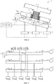
FIG. 4 is a cross-sectional side view of amotion system 28 configured to drive movement and/or rotation of the racer 10. Themotion system 28 is movably coupled to thetrack 18 viarollers 30. In certain embodiments, therollers 30 may include motors (e.g., electric motors) to drive rotational movement of therollers 30 to propel the racer 10 along thetrack 18 in the operation direction 20 (and/or the opposite direction). Accordingly, thevehicles 12 may travel along thetrack 18 to simulate a race. In other embodiments, therollers 30 may move along thetrack 18 via gravitational forces and/or any other suitable technique for driving the racer 10 along thetrack 18. Furthermore, abody 32 is coupled to and supports therollers 30. As will be appreciated, thebody 32 may be formed from metals (e.g., steel), composite materials (e.g., including carbon fiber), or the like. In the illustrated embodiment, thebody 32 includes apivot 34 that enables theguide 14 and thearms 16 to rotate about theguide axis 22, thereby adjusting the circumferential position of thevehicles 12 with respect to theguide axis 22. - In the illustrated embodiment, the
guide 14 includes afirst actuator 36 configured to drive rotational movement of theguide 14 about the guide axis 22 (and in some embodiments, movement of thearms 16 about the guide axis 22). For example, thefirst actuator 36 may be a yaw drive that transmits rotational movement between interlocking gears. Also, in other embodiments, thefirst actuator 36 may be a rotary actuator configured to drive rotation of theguide 14 upon receipt of a signal from a control system. Rotation of theguide 14 may adjust the position of thevehicles 12 relative to one another, thereby providing an illusion of onevehicle 12 passing another during a race. As will be described below, in certain embodiments, rotation of theguide 14 may not adjust the position of thevehicles 12. For example, in certain embodiments, thevehicles 12 may not be rotationally coupled to theguide 14. - As shown in
FIG. 4 , thearms 16 of thevehicles 12 are rotationally coupled to thepivot 34 to enable individual, selective rotation of thevehicles 12 about theguide axis 22 via a second actuator 38 (e.g., a respective second actuator for eachvehicle 12 or group of vehicles 12). As described above with respect to theguide 14, thesecond actuator 38 drives rotation of thearm 16 about theguide axis 22 to adjust the position of thevehicle 12 relative to theother vehicles 12. Accordingly, thevehicles 12 may be individually rotated about theguide axis 22 to independently adjust the position of thevehicles 12 relative to one another. However, in certain embodiments, thearms 16 may be coupled to theguide 14 such that rotation of theguide 14 about theguide axis 22 drives rotation of each of thearms 16 about theguide axis 22. For example, theguide 14 may include apin 40 driven by a biasingmember 42. In certain embodiments, the biasingmember 42 includes a linear actuator (e.g., a screw drive, a magnetic drive, an electric drive) that applies a force to drive thepin 40 toward thearm 16. Thepin 40 may engage arecess 44 in thearm 16 and thereby removably couple thearm 16 to theguide 14. As will be appreciated, thepins 40 may be positioned about a circumference of theguide 14 to enable thearms 16 to couple to theguide 14 at different circumferential positions about the circumference of theguide 14. Rotation and support may be facilitated by bearingboxes 45 adjacent the arms. - In certain embodiments, the
arms 16 includessensors 46 positioned on atopsurface 48 of thearms 16 between thearms 16 and theguide 14. However, it is understood that in embodiments where thearms 16 are positioned above the guide (e.g., relative to the track 18), that thesensors 46 may be positioned on a bottom surface of thearms 16 such that thesensors 46 are positioned between thearms 16 and theguide 14. Moreover, in other embodiments, thesensors 46 may be positioned on theguide 14. Thesensors 46 are configured to detect the position of thearms 16 relative to theguide 14. In other words, thesensors 46 are configured to detect the circumferential position of thearms 16 about theguide axis 22. For example, thesensors 46 may include Hall effect sensors, capacitive displacement sensors, optical proximity sensors, inductive sensors, string potentiometers, electromagnetic sensors, or any other suitable sensor. In certain embodiments, thesensors 46 are configured to send a signal indicative of a position of thearm 16 to a control system (e.g., local and/or remote). Accordingly, thesensors 46 may be utilized to adjust the position of thearms 16 about theguide axis 22 and/or to facilitate engagement (or disengagement) of thepins 40. - As mentioned above, the
motion system 28 may include acontrol system 50 configured to control movement and/or rotation of theguide 14 and/or thearms 16. Thecontrol system 50 includes acontroller 52 having amemory 54 and one ormore processors 56. For example, thecontroller 52 may be an automation controller, which may include a programmable logic controller (PLC). Thememory 54 is a non-transitory (not merely a signal), tangible, computer-readable media, which may include executable instructions that may be executed by theprocessor 56. That is, thememory 54 is an article of manufacture configured to interface with theprocessor 56. - The
controller 52 receives feedback from thesensors 46 and/or other sensors that detect the relative position of themotion system 28 along thetrack 18. For example, thecontroller 52 may receive feedback from thesensors 46 indicative of the position of thearms 16, and therefore thevehicles 12, relative to theother arms 16. Based on the feedback, thecontroller 52 may regulate operation of the racer 10 to simulate a race. For example, in the illustrated embodiment, thecontroller 52 is communicatively coupled to thefirst actuator 36, thesecond actuator 38, and the biasingmember 42. Based on feedback from thesensors 46, thecontroller 52 may instruct the first andsecond actuators guide 14 and/or thearms 16 to change the position of thevehicles 12 relative to one another. - Variations in the arrangement of the
arms 16 and the mechanism for driving thearms 16 in theoperation direction 20 are also within the scope of the present disclosure. For instance, referring briefly toFIG. 5 , eacharm 16 may be individually driven such that at least some overlap occurs. In such an embodiment, the arms may connect in offsetting positions along thepivot 34 to facilitate such overlap.FIG. 5 also illustrates an embodiment of the racer 10 without theguide 14 but including thebody 32 andbogies 33, which may be referred to as abogie system 57. - Furthermore, in certain embodiments, the
arms 16 may not have the same length (e.g., radial extent from the guide axis 22) or thevehicles 12 may be distanced differently along the lengths, thereby enabling thearms 16 to overlap one another as thearms 16 rotate about theguide axis 22 without having thevehicles 12 contact each other. Additionally, in some embodiments, thearms 16A and/or 16B may include a dogleg, a bend, or a curvature along a length of thearms 16, such that when thearms 16 overlap, a distance between thebody 32 of thevehicles 12 is reduced (e.g., the dogleg, the bend, and/or the curvature may enable the vehicles to overlap in a more compact configuration), as shown inFIG. 6 . Accordingly, passengers may receive enhanced amusement from a perception that thevehicles 12 may collide as a result of the reduced distance. - Returning now to the illustrated embodiment of
FIG. 4 , thecontroller 52 may be configured to include virtual position thresholds and/or electronic stops that may block thevehicles 12 from contacting one another based on feedback received from thesensors 46. In some embodiments, thearms 16 may include blockingmembers 58 extending from thearms 16 in a direction crosswise relative to a longitudinal axis of thearms 16. The blockingmembers 58 are configured to act as mechanical stops, which block thearms 16 from coming within a predetermined distance of one another. For example, the predetermined distance may be a distance that blocks thevehicles 12 from contacting one another during operation. Moreover, the blockingmembers 58 may be positioned at any radial distance along thearms 16, with respect to theguide axis 22. For example, in the illustrated embodiment, the blockingmembers 58 are positioned at approximately one-fourth the radial extent of thearms 16. However, in other embodiments, the blockingmembers 58 may be positioned at approximately one-third the radial extent of thearms 16, approximately one-half the radial extent of thearms 16, approximately three-fourths the radial extent of thearms 16, or any other suitable distance from theguide axis 22. As used herein, approximately refers to plus or minus five percent. Accordingly, the blockingmembers 58 may be configured to block thevehicles 12 from contacting one another during operation of the attraction. -
FIG. 7 is a cross-sectional side view of an embodiment of avehicle coupling system 60 configured to couple thevehicles 12 to thearms 16. In the illustrated embodiment, thevehicle 12 includes abody 62 coupled to avehicle pivot 64. Thevehicle pivot 64 may be driven to rotate about avehicle axis 66 via athird actuator 68. As a result, thebody 62 may be rotated about thevehicle axis 66, thereby enabling the rider to rotate about thevehicle axis 66 during operation of the attraction. For example, thebody 62 may rotate about thevehicle axis 66 while thevehicle 12 approaches a turn or curved portion of thetrack 18, thereby simulating a car steering into the curve. Moreover, arotation sensor 70 may be positioned proximate to thethird actuator 68 to determine the rotational position (e.g., the circumferential position) of thebody 62 relative to thevehicle axis 66. For example, thebody 62 may be driven to rotate about thevehicle axis 66 in thefirst rotation direction 24 and thesecond rotation direction 26. Therotation sensor 70 may output a signal to thecontroller 52 indicative of the rotation of thebody 62, thereby enabling thecontroller 52 to output signals to thethird actuator 68 to rotate thebody 62 to simulate driving along thetrack 18. - In the illustrated embodiment, the
third actuator 68 is coupled to aplatform 72 havingrollers 74 positioned on thearm 16. Therollers 74 enable theplatform 72, and therefore thebody 62, to move along thearm 16 in a firstradial direction 76 and a secondradial direction 78. As used herein, the firstradial direction 76 will refer to movement inwards and/or towards theguide axis 22. Moreover, the secondradial direction 78 will refer to movement outwards and/or away from theguide axis 22. Enabling movement of thevehicle 12 along thearm 16 enables different motion configurations. For example, this may be utilized to simulate the illusion of thevehicle 12 attempting to "pass" thevehicle 12 positioned immediately in front of thevehicle 12, as will be described in detail below. Moreover, movement of thevehicles 12 along thearm 16 may enable thevehicles 12 to get closer to one another during operation, thereby enhancing the excitement experienced by the rider. Additionally, thearms 16 may include a telescoping configuration that enables movement of the vehicles 12 (e.g., the body 62) in the first and secondradial directions rollers 74. Thearms 16 may include telescoping segments that may be powered by an actuator or other suitable device such that thevehicles 12 may move radially with respect to theguide axis 22. For example, thearms 16 may be configured to extend in the secondradial direction 78 such that thevehicles 12 move away from theguide axis 22 and retract in the first radial direction such that thevehicles 12 move toward theguide axis 22. However, in some embodiments, themotion system 28 does not include features for movement of thevehicles 12 radially along thearms 16. For example, thevehicles 12 may be rigidly or merely pivotably coupled to thearms 16. - As shown in the illustrated embodiment of
FIG. 7 , thebody 62 is configured to move along thearm 16 via therollers 74. In certain embodiments, therollers 74 may include an electric motor to drive (e.g., via a linkage) thevehicle 12 in the first and secondradial directions arm position sensor 80 may be positioned on theplatform 72. Thearm position sensor 80 is configured to output a signal indicative of the radial position of thevehicle 12 along thearm 16. For example, thearm position sensor 80 may be a capacitive displacement sensor that outputs a signal to thecontroller 52. In certain embodiments, movement along thearm 16 may be utilized to simulate thevehicle 12 moving into position to pass anothervehicle 12. Moreover, while the illustrated embodiment includes thearm position sensor 80 on theplatform 72, in other embodiments thearm position sensor 80 may be positioned on thearm 16. - In still further embodiments, the
body 62 may be configured to move in the first and secondradial directions adjustable swash plate 81 as thearm 16. For example,FIG. 8 is a cross-sectional side view of another embodiment of thevehicle coupling system 60 that utilizes theadjustable swash plate 81 and therollers 74. As shown in the illustrated embodiment ofFIG. 8 , theadjustable swash plate 81 may move in a firstvertical direction 82 and/or a secondvertical direction 83 via one ormore actuators 84. Accordingly, rather than utilizing an electric motor to move thebody 62 in the first and secondradial directions more actuators 84 may adjust the position of theadjustable swash plate 81, such that thebody 62 moves in the first and secondradial directions body 62. Such an embodiment may be desirable because riders may experience enhanced amusement as a result of thevehicle 12 rotating along an axis 85 (e.g., theaxis 85 is defined by the operation direction 20), and thus moving with an additional degree of freedom. - In some embodiments, the one or
more actuators 84 may be coupled to thecontroller 52, which may activate and/or deactivate the one ormore actuators 84 to move thebody 62 in the first and secondradial directions controller 52 may receive feedback from thearm position sensor 80 to determine a position of thebody 62 along the arm 16 (e.g., the adjustable swash plate 81), and send one or signals to theactuators 84 to adjust the position of thebody 62 to a desired location. As discussed above, movement of thebody 62 in the first and secondradial directions vehicles 12 to move with respect to one another and create a perception that thevehicles 12 are racing one another. Additionally, in other embodiments, theadjustable swash plate 81 may be utilized to adjust a position of theguide 14, which may enable thearms 16 to overlap with one another. -
FIG. 9 is a schematic of another embodiment of the racer 10 that may include multipleadjustable swash plates 81. In the illustrated embodiment ofFIG. 9 , theadjustable swash plates 81 includerotatable plates 86, which may be coupled to thearms 16. In some embodiments, therotatable plates 86 may form a ring along a perimeter of theadjustable swash plates 81. Therotatable plates 86 may rotate with respect to theadjustable swash plates 81, thereby rotating thearms 16 and thevehicles 12. To rotate therotatable plates 86,motors 87 may supply power to a driving device 88 (e.g., gears, wheels, tires, and/or rotatable actuators), which may directrotatable plates 86 in thefirst rotation direction 24 and/or thesecond rotation direction 26. Theadjustable swash plates 81 may each include one or more of theactuators 84, which may enable movement of thevehicles 12 in the firstvertical direction 82 and/or the secondvertical direction 83. Accordingly, eachvehicle 12 may rotate in thefirst rotation direction 24 and/or thesecond rotation direction 26 independent from theother vehicles 12, and eachvehicle 12 may move in the firstvertical direction 82 and/or the secondvertical direction 83 independent from theother vehicles 12. -
FIG. 10 is a top view of an embodiment of the racer 10 having three vehicles in which thevehicles 12 are traveling along thetrack 18 in theoperation direction 20. As shown, afirst vehicle 90 is in afirst place position 92. While in thefirst place position 92, thefirst vehicle 90 is at afirst distance 94, relative to the a movingaxis 95 that is orthogonal to the intersection of theguide axis 22 and theoperation direction 20 and extending along a plane defined by thesurface 21. As a result, thefirst vehicle 90 may be described as being in "first place" relative to asecond vehicle 96 and athird vehicle 98. Additionally, thesecond vehicle 96 is at asecond place position 100. While in thesecond place position 100, thesecond vehicle 96 is at asecond distance 102, relative to the movingaxis 95. Accordingly, thesecond vehicle 96 may be described as being in "second place" relative to thefirst vehicle 90 and thethird vehicle 98. Furthermore, thethird vehicle 98 is in athird place position 104. While in thethird place position 104, thethird vehicle 98 is at athird distance 106, relative to the movingaxis 95. As a result, thethird vehicle 98 may be described as being in "third place" relative to thefirst vehicle 90 and thesecond vehicle 96. It will be understood that respective lengths of the first, second, andthird distances first distance 94 corresponds to thefirst place position 92, thesecond distance 102 corresponds to thesecond place position 100, and thethird distance 102 corresponds to thethird place position 104, notwithstanding the numeric values of the first, second, andthird distances - In the illustrated embodiment, the
first vehicle 90 is at afirst angle 108, relative to thesecond vehicle 96. As will be appreciated, thefirst angle 108 may be adjusted via the first actuator 36 (via coupling of thearms 16 to the guide 14) and/or via thesecond actuator 38. As mentioned above, thesecond actuator 38 may be a yoke drive configured to engage corresponding gears of thearms 16. In certain embodiments, thearms 16 may be individually rotatable about theguide axis 22 by selectively engagingindividual arms 16 with thesecond actuator 38. As a result, thefirst angle 108 may be adjusted during operation of the attraction. Moreover, thefirst vehicle 90 may be at asecond angle 110, relative to thethird vehicle 98. Additionally, thesecond vehicle 96 may be at athird angle 112, relative to thethird vehicle 98. As will be described below, the relative angles between the first, second, andthird vehicles - As shown in
FIG. 10 , thefirst vehicle 90 is positioned at adistal end 114 of afirst arm 116. In other words, therollers 74 may drive theplatform 72 in the secondradial direction 78 such that thefirst vehicle 90 is at afirst radial distance 118 from theguide axis 22. However, thesecond vehicle 96 is positioned at approximately a mid-point of asecond arm 120 via movement in the firstradial direction 76 byrollers 74, for example. As a result, thesecond vehicle 96 is at a second radial distance 122 from theguide axis 22. In the illustrated embodiment, the second radial distance 122 is less than thefirst radial distance 118. However, in other embodiments, thefirst radial distance 118 may be smaller than the second radial distance 122, or thefirst radial distance 118 may be equal to the second radial distance 122. Moreover, in the illustrated embodiment, thethird vehicle 98 is at a thirdradial distance 124 along athird arm 125 via movement in the firstradial direction 76. As shown, the thirdradial distance 124 is less than thefirst radial distance 118, and greater than the second radial distance 122. Accordingly, radial distance of the first, second, andthird vehicles guide axis 22. As a result, the riders may experience enhanced excitement during operations because thevehicles 12 are configured to move in a variety of directions relative to theguide axis 22. - As described above, the
arms 16 are configured to rotate about theguide axis 22 to simulate a race between thevehicles 12. In the illustrated embodiment, thefirst vehicle 90 and thethird vehicle 98 are positioned on afirst side 126 of thetrack 18. Moreover, thesecond vehicle 96 is positioned on asecond side 128. During operation of the attraction, thevehicles 12 may rotate about theguide axis 22, and thereby move between the first andsecond sides vehicles 12 may be substantially aligned with thetrack 18. Furthermore, movement from thefirst side 126 to thesecond side 128 may be driven by thesecond actuator 38 as thesecond actuator 38 selectively drives rotation of thearms 16. However, in other embodiments, thearms 16 may be locked to theguide 14, via thepin 40, and thefirst actuator 36 may drive rotation of theguide 14 about theguide axis 22, and thereby facilitate a corresponding rotation of thearms 16 about theguide axis 22. Accordingly, thevehicles 12 may be driven to rotate about theguide axis 22 to simulate movement along a raceway during operation of the attraction. -
FIG. 11 is a top view of an embodiment of the racer 10 in which thefirst vehicle 90 is in thefirst place position 92 and thethird vehicle 98 is in thesecond place position 100. Comparing the position of the first, second, andthird vehicles FIG. 10 to FIG. 11 thefirst vehicle 90 remains in thefirst place position 92, but has moved to thesecond side 128 of thetrack 18. Moreover, thethird vehicle 98 has moved to thesecond place position 100. Additionally, thesecond vehicle 96 has moved to thethird place position 104. In the illustrated embodiment, rotation of theguide 14 about theguide axis 22 may drive thevehicles 12 to rotate about theguide axis 22, via engagement of thepins 40. For example, as shown inFIGS. 8 and 9 , thefirst vehicle 90 rotates about theguide axis 22 in thesecond rotation direction 26 to move to thesecond side 128. Moreover, thefirst angle 108 remains substantially unchanged betweenFIGS. 8 and 9 . However, in other embodiments, thesecond actuator 38 may drive individual movement of thearms 16 about theguide axis 22. In other words, thefirst angle 108,second angle 110, andthird angle 112 may change as thevehicles 12 move between thefirst place position 92, thesecond place position 100, and thethird place position 104. - Furthermore, as the
vehicles 12 move between thefirst place position 92, thesecond place position 100, and thethird place position 104, thevehicles 12 may rotate about thevehicle axis 66 to orient afront end 130 of thevehicles 12 along theoperation direction 20. For example, in the illustrated embodiment ofFIG. 11 , thetrack 18 is substantially straight, and as a result the front ends 130 of thevehicles 12 are oriented along the path of thetrack 18. However, in other embodiments, thefront end 130 may be not oriented along theoperation direction 20. For example, thevehicles 12 may be configured to "spin out" or "drift" along a sharp curve. Accordingly, the rotation of thevehicles 12 may be controlled to point the front ends 130 away from the operation direction 20 (e.g., in an opposite direction, in a direction substantially perpendicular). Rotation of thevehicles 12 about thevehicle axis 66 may enhance excitement for riders and increase variability of the outcomes of the races between thevehicles 12. -
FIG. 12 is a top view of the racer 10 in which thetrack 18 is arcuate. As shown, thetrack 18 includes a bend or curve to simulate a turn. Because theoperation direction 20 is substantially along the curve of thetrack 18, thefirst vehicle 90 and thethird vehicle 98 are driven to rotate about therespective vehicle axis 66 to orient the front ends 130 along theoperation direction 20. However, as mentioned above, thesecond vehicle 96 may be in a spin outposition 132, as shown in the illustrated embodiment ofFIG. 12 . As shown, rotation about thevehicle axis 66 of thesecond vehicle 96 orients thefront end 130 out of alignment with theoperation direction 20. Accordingly, the riders may experience the sensation of losing control of theirvehicle 12 around the curve. In certain embodiments, thecontroller 52 may be configured to direct rotation of thesecond vehicle 96 about theguide axis 22 toward thethird position 104 to simulate the impact of the spin out during the race with the first andthird vehicles vehicles 12 that spin-out may fall behind theother vehicles 12 in the race. - Furthermore, as shown in
FIG. 12 , the blockingmembers 58 of thefirst vehicle 90 and thethird vehicle 98 are in contact with one another. As described above, the blockingmembers 58 are positioned along thearms 16 to block contact between thevehicles 12 as thevehicles 12 rotate about theguide axis 22. For example, the blockingmembers 58 may be positioned on thearms 16 to enable thearms 16 to come within a predetermined angle of one another. In certain embodiments, the predetermined angle may enable rotation of thevehicles 12 about thevehicle axis 66 without contacting theadjacent vehicle 12. -
FIG. 13 is a top view of an embodiment of the racer 10 in which afirst guide 134 is coupled to asecond guide 136 via anattachment member 138. In the illustrated embodiment, thefirst guide 134 includes asingle vehicle 12 and thesecond guide 136 includes asingle vehicle 12. However, in other embodiments, the first andsecond guides vehicles 12. Moreover, in other embodiments the first andsecond guides vehicles 12. For example, thefirst guide 134 may include twovehicles 12 while thesecond guide 136 includes asingle vehicle 12. In the illustrated embodiment, theattachment member 138 is configured to couple thesecond guide 136 to thefirst guide 134, thereby enabling riders in the first andsecond guides second guide 136 may couple to thefirst guide 134 during operation of the attraction to simulate thesecond guide 136 catching up to thefirst guide 134. Thereafter, thevehicles 12 of the respective first andsecond guides respective guide axis 22 as described in detail above. Moreover, while the illustrated embodiment includes the first andsecond guides attachment member 138. -
FIG. 14 is a flow chart of an embodiment of amethod 140 for controlling the racer 10 during operation. At block 142, a plurality of thevehicles 12 may be directed in theoperation direction 120 along thetrack 18 using theguide 14. Additionally, at block 144, one ormore vehicles 12 of the plurality ofvehicles 12 may be rotated about theguide axis 22 such that a position of the one ormore vehicles 12 of the plurality ofvehicles 12 may be adjusted with respect to the remainingvehicles 12 of the plurality ofvehicles 12. In some embodiments, movement of thevehicles 12 in the operation direction 120 (e.g., gross movement) may be automated (e.g., a ride controller moves theguide 14 along thetrack 18 at a predetermined speed). However, in certain embodiments, movement of thevehicles 12 about the guide axis 22 (e.g., fine movement) may be controlled by the riders, themselves. Accordingly, the riders may ultimately have control over a position of thevehicles 12 with respect to one another at the end of the ride. - Additionally, a starting position of the
vehicle 12 may be determined at by thecontroller 52, for example. Thesensor 46 may transmit a signal to thecontroller 52 indicative of thearms 16 relative location along the circumference of theguide 14. In some embodiments, thecontroller 52 may determine the starting position (e.g., thefirst place position 92, thesecond place position 100, the third place position 104) based on the signal from thesensor 46. Theoperation direction 20 may also be determined. For example, sensors positioned on theguide 14 may determine the relative location of theguide 14 along thetrack 18, and thereby determine the shape of thetrack 18 and theoperation direction 20. Thecontroller 52 may send a signal to thevehicle 12 to rotate about thevehicle axis 66. For example, thetrack 18 may include a curved portion that adjusts theoperation direction 20. Thecontroller 52 may instruct thevehicle 12 to rotate about thevehicle axis 66 to align thefront end 130 of thevehicle 12 with theoperation direction 20. Moreover, in other embodiments, thecontroller 52 may instruct thevehicle 12 to rotate about thevehicle axis 66 to simulate a spin out or out-of-control condition. Further, a desired position of thevehicle 12 may be predetermined by the controller 52 (e.g., as opposed to controlled by the riders themselves). For example, thecontroller 52 may determine thefirst vehicle 90 will finish in thesecond place position 100. Thecontroller 52 may then instruct thevehicle 12 to rotate about theguide axis 22. For example, thecontroller 52 may determine that thefirst vehicle 90 will finish in thesecond position 100 after starting in thethird place position 104. Thecontroller 52 may send a signal to thesecond actuator 38 to drive rotation of thefirst vehicle 90 about theguide axis 22 to move thefirst vehicle 90 into thesecond place position 100. - As described in detail above, the
motion system 28 of the racer 10 may drive rotational movement of thevehicles 12 about theguide axis 22. For example, thesecond actuator 38 may be configured to drive rotation of thearms 16 coupled to thevehicles 12. Furthermore, in other embodiments, thearms 16 may be coupled to theguide 14 to enable rotation of thevehicles 12 while theguide 14 is driven to rotate about theguide axis 22. In certain embodiments, thevehicles 12 are configured to rotate about thevehicle axis 66. Rotation about thevehicle axis 66 enables alignment of thefront end 130 of thevehicles 12 with theoperation direction 20, thereby enhancing the simulation of driving along thetrack 18. Moreover, rotation about thevehicle axis 66 may facilitate spin-outs or drifting around curves during operation of the attraction. In certain embodiments, thecontrol system 50 may be configured to control movement of thevehicles 12 during operation of the attraction. For example, thecontroller 52 may send or receive signals to drive rotation of thevehicles 12 about theguide axis 22 and/or about thevehicle axis 66. Accordingly, the racer 10 may simulate a race betweenvehicles 12 to provide entertainment to riders utilizing the attraction. - While only certain features of the present disclosure have been illustrated and described herein, many modifications and changes will occur to those skilled in the art. It is, therefore, to be understood that the appended claims are intended to cover all such modifications and changes as fall within the true spirit of the present disclosure.
- A system in an embodiment comprises a bogie system positioned on a track, wherein the bogie system is configured to move along the track in an operating direction a plurality of arms extending radially outward from the bogie system, wherein each of the plurality of arms is individually rotatably coupled to a body of the bogie system, and a plurality of vehicles, wherein each vehicle of the plurality of vehicles is positioned on a corresponding arm of the plurality of arms, and wherein the bogie system is configured to move the plurality of arms and the plurality of vehicles together along the operation direction, and wherein the plurality of vehicles are positioned at different locations with respect to the operation direction.
- The system may comprise a controller configured to control rotation of each arm of the plurality of arms about the body of the bogie system and to control translation of each vehicle of the plurality of vehicles along the corresponding arm.
- The system may comprise one or more sensors configured to send feedback to the controller indicative of a respective position of each vehicle of the plurality of vehicles with respect to the track and with respect to the other vehicles of the plurality of vehicles.
- The controller may be configured to send a first signal to an actuator coupled to the body of the bogie system to rotate the plurality of arms about the body of the bogie system, and the controller may be configured to send a second signal to an electric motor configured to power rollers to translate each of the vehicles along the corresponding arm.
- The controller may comprise virtual position thresholds configured to block the plurality of vehicles from contacting one another.
- The controller may be configured to control rotation of each vehicle of the plurality of vehicles about a respective vehicle axis.
- The controller may be configured to rotate each vehicle of the plurality of vehicles about the respective vehicle axis based on a respective position of each vehicle of the plurality of vehicles with respect to the track.
- In accordance with a further aspect, there is provided an apparatus for an amusement park, comprising: a first bogie system positioned on a track, wherein the first bogie system is configured to direct motion along the track; a first arm extending radially outward from the first bogie system, wherein the first arm is rotatably coupled to a first body of the first bogie system; and a first vehicle configured to carry a passenger and positioned on the first arm, wherein the first bogie system is configured to move in an operation direction along the track and the first vehicle is configured to rotate about the first bogie system to change a position of the first vehicle with respect to the first bogie system, and wherein the first vehicle is configured to move radially along a length of the first arm.
- The first arm may comprise rollers, telescoping segments, or an adjustable swash plate, configured to enable the first vehicle to move radially along the length of the first arm.
- The apparatus may comprise a plurality of the arms extending radially outward from the first bogie system, each arm of the plurality of the arms having a corresponding vehicle coupled thereto.
- The corresponding vehicles may be positioned at different locations from one another with respect to the first bogie system.
- Each of the plurality of the arms may be positioned offset from one another with respect to a rotational axis of the first body of the first bogie system.
- Each of the plurality of the arms may comprise a blocking device configured to block contact between the corresponding vehicles.
- The apparatus may comprise a controller configured to determine a position of the first vehicle relative to the first arm and the track.
- The apparatus may comprise a counterweight extending radially outward from the first bogie system in a direction opposite of the first arm, wherein the counterweight is rotatably coupled to the first body of the first bogie system.
- The apparatus may comprise a second bogie system, a second arm, and a second vehicle, wherein the second bogie system is coupled to the first bogie system and is positioned on the track, wherein the second arm extends radially outward from the second bogie system, wherein the second arm is rotatably coupled to a second body of the second bogie system, wherein the second vehicle is positioned on the second arm, and wherein the second bogie system is configured to move in the operation direction along the track and the second vehicle is configured to rotate about the second bogie system to change position of the second vehicle with respect to the second bogie system.
- The first vehicle, the second vehicle, or both may be configured to rotate about a vehicle axis based on the operation direction along the track.
- The first vehicle and the second vehicle may be configured to independently rotate about the first bogie system and the second bogie system respectively to change the first position and the second position, respectively.
- In accordance with a further aspect, there is provided a method for controlling an amusement ride with an automation controller and actuators, comprising: directing a plurality of vehicles in an operation direction along a track using a shared bogie system and a motor actuator; rotating one or more of the vehicles of the plurality of vehicles about a guide axis with a rotation actuator to adjust a position of the one or more vehicles of the plurality of vehicles with respect to the remaining vehicles of the plurality of vehicles; and moving one or more of the vehicles radially along a length of an arm.
- The method may comprise rotating the vehicle of the plurality of vehicles about a vehicle axis based on the operating direction of the vehicle.
- Rotating the one or more of the vehicles of the plurality of vehicles about the guide axis may be controlled by a rider carried in the ride vehicle.
- The method may comprise receiving signals from a sensor informing the controller of the arms' relative location along the circumference of a guide.
Claims (15)
- An apparatus for an amusement park, comprising:a bogie system (57) positioned on a track (18);an arm (16) extending radially outward from the bogie system (57), wherein the arm (16) is rotatably coupled to a body (32) of the bogie system (57);a vehicle (12) configured to carry a passenger and positioned on the arm (16), wherein the bogie system (57) is configured to move in an operation direction along the track (18) and the vehicle (12) is configured to rotate about the bogie system (57) to change a position of the vehicle (12) with respect to the bogie system (57); andan actuator (84) configured to move the arm (16) and the vehicle (12) in a vertical direction substantially crosswise to the operation direction along the track (18).
- The apparatus of Claim 1, wherein the actuator (84) comprises an adjustable swash plate (81) configured to rotate the arm (16) about an axis defined by the operation direction along the track.
- The apparatus of Claim 1, comprising a controller coupled to the actuator (84), wherein the controller is configured to control the actuator (84) to adjust a position of the arm (16) and the vehicle (12) with respect to the vertical direction.
- The apparatus of Claim 3, comprising a sensor communicatively coupled to the controller, wherein the sensor is configured to provide feedback to the controller indicative of a position of the vehicle (12) relative to the bogie system (57), and wherein the controller is configured to adjust the actuator (84) based on the feedback.
- The apparatus of Claim 1, comprising a plurality of the arms extending radially outward from the bogie system (57), wherein each arm (16) of the plurality of arms is rotatably coupled to a body of the bogie system (57), and optionally wherein each arm of the plurality of arms is configured to independently rotate about the bogie system with respect to remaining arms of the plurality of arms.
- The apparatus of Claim 5, wherein a first arm of the plurality of arms is vertically offset from a second arm of the plurality of arms with respect to the vertical direction.
- The apparatus of Claim 5 or Claim 6, comprising a plurality of vehicles (12), wherein each vehicle (12) of the plurality of vehicles is positioned on a corresponding arm (16) of the plurality of arms, and wherein the bogie system (57) is configured to move the plurality of arms and the plurality of vehicles together along the operating direction.
- The apparatus of Claim 7, comprising a plurality of swash plates (81), wherein each swash plate (81) of the plurality of swash plates is coupled to a corresponding arm (16) of the plurality of arms, and wherein each swash plate (81) of the plurality of swash plates is configured to move a corresponding vehicle (12) of the plurality of vehicles in a vertical direction that is substantially crosswise to the operating direction.
- The apparatus of Claim 8, comprising a plurality of rotatable plates, wherein each rotatable plate of the plurality of rotatable plates is coupled to a corresponding swash plate (81) of the plurality of swash plates and to the corresponding arm (16) of the plurality of arms, and wherein each rotatable plate of the plurality of rotatable plates is configured to rotate with respect to the corresponding swash plate (81) of the plurality of swash plates to rotate the corresponding arm (16) of the plurality of arms about the body of the bogie system.
- The apparatus of Claim 9, wherein each rotatable plate of the plurality of rotatable plates forms a ring along a perimeter of the corresponding swash plate (81) of the plurality of swash plates.
- The apparatus of any of Claims 8 to 10, comprising a controller (52) configured to control rotation of each arm (16) of the plurality of arms about the body of the bogie system (57) and to control each swash plate (81) of the plurality of swash plates to adjust a position of each vehicle (12) of the plurality of vehicles with respect to the vertical direction.
- The apparatus of Claim 11, comprising a plurality of actuators (84), wherein each actuator of the plurality of actuators (84) is coupled to a corresponding vehicle (12) of the plurality of vehicles, wherein each actuator of the plurality of actuators is configured to rotate the corresponding vehicle (12) of the plurality of vehicles about a vehicle axis and to rotate the corresponding vehicle of the plurality of vehicles with respect to the corresponding arm (16) of the plurality of arms, and optionally wherein the controller (52) is configured to control each actuator (84) of the plurality of actuators to adjust a position of each vehicle (12) of the plurality of vehicles with respect to a corresponding vehicle axis (85).
- The apparatus of Claim 1, comprising an additional actuator (84) configured to rotate the vehicle (16) about a vehicle axis (85), and optionally wherein the additional actuator (84) comprises a gear assembly driven by an electric motor (87).
- The apparatus of Claim 1, wherein the arm (16) is a telescoping arm configured to enable radial movement of the vehicle (12) with respect to the bogie system (57), or wherein the arm (16) comprises a dogleg, a bend, a curvature, or a combination thereof, along a length of the arm.
- The apparatus of Claim 1, further comprising rollers (74) disposed between a body of the vehicle (12) and the actuator (84), wherein the rollers (74) are configured to move the vehicle (12) in a radial direction along the arm (16) when the actuator (84) moves in the vertical direction.
Priority Applications (1)
| Application Number | Priority Date | Filing Date | Title |
|---|---|---|---|
| EP26152606.5A EP4725571A3 (en) | 2015-03-31 | 2016-03-31 | System and method for positioning vehicles of an amusement park attraction |
Applications Claiming Priority (5)
| Application Number | Priority Date | Filing Date | Title |
|---|---|---|---|
| US201562141086P | 2015-03-31 | 2015-03-31 | |
| US15/085,910 US10105609B2 (en) | 2015-03-31 | 2016-03-30 | System and method for positioning vehicles of an amusement park attraction |
| EP16715763.5A EP3277395B1 (en) | 2015-03-31 | 2016-03-31 | System and method for positioning vehicles of an amusement park attraction |
| EP19164769.2A EP3530332B1 (en) | 2015-03-31 | 2016-03-31 | System and method for positioning vehicles of an amusement park attraction |
| PCT/US2016/025289 WO2016161128A1 (en) | 2015-03-31 | 2016-03-31 | System and method for positioning vehicles of an amusement park attraction |
Related Parent Applications (2)
| Application Number | Title | Priority Date | Filing Date |
|---|---|---|---|
| EP19164769.2A Division EP3530332B1 (en) | 2015-03-31 | 2016-03-31 | System and method for positioning vehicles of an amusement park attraction |
| EP16715763.5A Division EP3277395B1 (en) | 2015-03-31 | 2016-03-31 | System and method for positioning vehicles of an amusement park attraction |
Related Child Applications (1)
| Application Number | Title | Priority Date | Filing Date |
|---|---|---|---|
| EP26152606.5A Division EP4725571A3 (en) | 2015-03-31 | 2016-03-31 | System and method for positioning vehicles of an amusement park attraction |
Publications (2)
| Publication Number | Publication Date |
|---|---|
| EP3900801A1 true EP3900801A1 (en) | 2021-10-27 |
| EP3900801B1 EP3900801B1 (en) | 2026-01-28 |
Family
ID=55702178
Family Applications (4)
| Application Number | Title | Priority Date | Filing Date |
|---|---|---|---|
| EP19164769.2A Active EP3530332B1 (en) | 2015-03-31 | 2016-03-31 | System and method for positioning vehicles of an amusement park attraction |
| EP26152606.5A Pending EP4725571A3 (en) | 2015-03-31 | 2016-03-31 | System and method for positioning vehicles of an amusement park attraction |
| EP16715763.5A Active EP3277395B1 (en) | 2015-03-31 | 2016-03-31 | System and method for positioning vehicles of an amusement park attraction |
| EP21162694.0A Active EP3900801B1 (en) | 2015-03-31 | 2016-03-31 | System and method for positioning vehicles of an amusement park attraction |
Family Applications Before (3)
| Application Number | Title | Priority Date | Filing Date |
|---|---|---|---|
| EP19164769.2A Active EP3530332B1 (en) | 2015-03-31 | 2016-03-31 | System and method for positioning vehicles of an amusement park attraction |
| EP26152606.5A Pending EP4725571A3 (en) | 2015-03-31 | 2016-03-31 | System and method for positioning vehicles of an amusement park attraction |
| EP16715763.5A Active EP3277395B1 (en) | 2015-03-31 | 2016-03-31 | System and method for positioning vehicles of an amusement park attraction |
Country Status (11)
| Country | Link |
|---|---|
| US (3) | US10105609B2 (en) |
| EP (4) | EP3530332B1 (en) |
| JP (3) | JP6526232B2 (en) |
| KR (2) | KR102606025B1 (en) |
| CN (2) | CN110478912B (en) |
| CA (1) | CA2980594C (en) |
| ES (3) | ES3063387T3 (en) |
| MY (2) | MY205885A (en) |
| RU (2) | RU2020104061A (en) |
| SG (2) | SG10201912246SA (en) |
| WO (1) | WO2016161128A1 (en) |
Families Citing this family (13)
| Publication number | Priority date | Publication date | Assignee | Title |
|---|---|---|---|---|
| US10105609B2 (en) * | 2015-03-31 | 2018-10-23 | Universal City Studios Llc | System and method for positioning vehicles of an amusement park attraction |
| US11241633B2 (en) * | 2018-10-05 | 2022-02-08 | Universal City Studios Llc | Hybrid ride vehicle systems and methods |
| US10688401B1 (en) * | 2019-01-08 | 2020-06-23 | Universal City Studios Llc | System and method to control entertainment figures |
| US11071922B2 (en) * | 2019-04-01 | 2021-07-27 | Universal City Studios Llc | Rotating platform coaster |
| US11400886B2 (en) * | 2019-05-23 | 2022-08-02 | Universal City Studios Llc | Systems and methods for deterring guest evacuations |
| US10843093B1 (en) * | 2019-06-24 | 2020-11-24 | Universal City Studios Llc | Ride systems having dynamic ride vehicle movement |
| JP7238668B2 (en) * | 2019-07-23 | 2023-03-14 | 株式会社三洋物産 | game machine |
| JP7238664B2 (en) * | 2019-07-23 | 2023-03-14 | 株式会社三洋物産 | game machine |
| JP7238666B2 (en) * | 2019-07-23 | 2023-03-14 | 株式会社三洋物産 | game machine |
| JP7238667B2 (en) * | 2019-07-23 | 2023-03-14 | 株式会社三洋物産 | game machine |
| JP7238665B2 (en) * | 2019-07-23 | 2023-03-14 | 株式会社三洋物産 | game machine |
| JP7238663B2 (en) * | 2019-07-23 | 2023-03-14 | 株式会社三洋物産 | game machine |
| JP7238661B2 (en) * | 2019-07-23 | 2023-03-14 | 株式会社三洋物産 | game machine |
Citations (6)
| Publication number | Priority date | Publication date | Assignee | Title |
|---|---|---|---|---|
| US1549927A (en) * | 1924-02-02 | 1925-08-18 | James A Sherry | Amusement device |
| US20090272289A1 (en) * | 2008-05-05 | 2009-11-05 | Disney Enterprises, Inc. | Amusement park ride with vehicles pivoting about a common chassis to provide racing and other effects |
| EP2301637A2 (en) * | 2009-09-23 | 2011-03-30 | Disney Enterprises, Inc. | Amusement park ride using motion-driven positioning for 360-degree vehicle orientation |
| US20120149480A1 (en) * | 2010-12-13 | 2012-06-14 | Disney Enterprises, Inc. | Twister ride system |
| US20130059670A1 (en) * | 2011-09-06 | 2013-03-07 | Disney Enterprises, Inc. | Omnitable ride system |
| WO2015040195A1 (en) * | 2013-09-20 | 2015-03-26 | Antonio Zamperla S.P.A. | Amusement device |
Family Cites Families (19)
| Publication number | Priority date | Publication date | Assignee | Title |
|---|---|---|---|---|
| FR2623318A1 (en) * | 1987-11-12 | 1989-05-19 | Roche Jean Jose | ASCENSIONAL EFFECT HANDWARE EQUIPPED WITH AN AIRCRAFT |
| JPH0386187A (en) * | 1989-08-30 | 1991-04-11 | Senyo Kiko Kk | Amusement vehicle traveling on track |
| US5403238A (en) * | 1993-08-19 | 1995-04-04 | The Walt Disney Company | Amusement park attraction |
| JP3668267B2 (en) | 1994-11-04 | 2005-07-06 | ビイエルデイオリエンタル株式会社 | Amusement vehicle equipment |
| DE19742260C2 (en) | 1997-09-25 | 2001-10-31 | Knijpstra Konstr Bv | carousel |
| US6047645A (en) * | 1998-06-26 | 2000-04-11 | Setpoint Engineered Systems, Inc. | Truss track assembly and side mount roller coaster vehicle |
| JP4577966B2 (en) | 1999-12-16 | 2010-11-10 | ビーエルデーオリエンタル株式会社 | Play equipment |
| DE10203729B4 (en) * | 2002-01-30 | 2006-12-14 | Kuka Roboter Gmbh | Driving device, in particular for amusement parks, trade fairs or the like |
| DE102006054116B3 (en) * | 2006-11-15 | 2008-04-17 | Mack Rides Gmbh & Co Kg | Rail-mounted vehicle i.e. roller coaster, for amusement ride, has magnet fixedly arranged in area of railway track, and brake disk connected with upper part of vehicle and/or vice versa |
| EP2173446A4 (en) | 2007-07-02 | 2012-02-08 | S & S Worldwide Inc | Longitudinally spinning suspension roller coaster |
| EP2175951B1 (en) * | 2007-08-16 | 2012-11-21 | Vekoma Rides Engineering B.V. | A rollercoaster amusement device |
| KR100987925B1 (en) * | 2010-06-21 | 2010-10-18 | 베르아델 승마클럽(주) | Horse-riding apparatus for amusement park |
| US8360893B2 (en) * | 2010-06-24 | 2013-01-29 | Disney Enterprises, Inc. | Roller coaster vehicle |
| US8348776B2 (en) * | 2010-07-08 | 2013-01-08 | Disney Enterprises, Inc. | Intersecting path ride |
| EP2824096A1 (en) | 2013-07-09 | 2015-01-14 | Solvay SA | Fluorinated carbonates comprising double bond-containing groups, methods for their manufacture and uses thereof |
| US20150021773A1 (en) * | 2013-07-22 | 2015-01-22 | Conversant Intellectual Property Management Inc. | Through Semiconductor via Structure with Reduced Stress Proximity Effect |
| US9272224B2 (en) | 2014-03-06 | 2016-03-01 | Disney Enterprises, Inc. | Amusement park ride with cantilevered ride vehicles |
| CN104225921B (en) * | 2014-06-03 | 2015-12-09 | 浙江科技学院 | A kind of fitness and entertainment facility |
| US10105609B2 (en) * | 2015-03-31 | 2018-10-23 | Universal City Studios Llc | System and method for positioning vehicles of an amusement park attraction |
-
2016
- 2016-03-30 US US15/085,910 patent/US10105609B2/en active Active
- 2016-03-31 EP EP19164769.2A patent/EP3530332B1/en active Active
- 2016-03-31 SG SG10201912246SA patent/SG10201912246SA/en unknown
- 2016-03-31 WO PCT/US2016/025289 patent/WO2016161128A1/en not_active Ceased
- 2016-03-31 RU RU2020104061A patent/RU2020104061A/en unknown
- 2016-03-31 CN CN201910776459.3A patent/CN110478912B/en active Active
- 2016-03-31 ES ES21162694T patent/ES3063387T3/en active Active
- 2016-03-31 JP JP2017551614A patent/JP6526232B2/en active Active
- 2016-03-31 SG SG11201707716RA patent/SG11201707716RA/en unknown
- 2016-03-31 KR KR1020177031116A patent/KR102606025B1/en active Active
- 2016-03-31 MY MYPI2021002605A patent/MY205885A/en unknown
- 2016-03-31 ES ES19164769T patent/ES2877192T3/en active Active
- 2016-03-31 ES ES16715763T patent/ES2743554T3/en active Active
- 2016-03-31 KR KR1020237039512A patent/KR102727966B1/en active Active
- 2016-03-31 EP EP26152606.5A patent/EP4725571A3/en active Pending
- 2016-03-31 MY MYPI2017001369A patent/MY189903A/en unknown
- 2016-03-31 EP EP16715763.5A patent/EP3277395B1/en active Active
- 2016-03-31 CA CA2980594A patent/CA2980594C/en active Active
- 2016-03-31 EP EP21162694.0A patent/EP3900801B1/en active Active
- 2016-03-31 RU RU2017134807A patent/RU2714653C2/en active
- 2016-03-31 CN CN201680031825.7A patent/CN107847803B/en active Active
-
2018
- 2018-10-22 US US16/167,209 patent/US11033828B2/en active Active
-
2019
- 2019-05-07 JP JP2019087460A patent/JP6926145B2/en active Active
-
2021
- 2021-06-14 US US17/347,409 patent/US12168184B2/en active Active
- 2021-08-04 JP JP2021128045A patent/JP7171852B2/en active Active
Patent Citations (6)
| Publication number | Priority date | Publication date | Assignee | Title |
|---|---|---|---|---|
| US1549927A (en) * | 1924-02-02 | 1925-08-18 | James A Sherry | Amusement device |
| US20090272289A1 (en) * | 2008-05-05 | 2009-11-05 | Disney Enterprises, Inc. | Amusement park ride with vehicles pivoting about a common chassis to provide racing and other effects |
| EP2301637A2 (en) * | 2009-09-23 | 2011-03-30 | Disney Enterprises, Inc. | Amusement park ride using motion-driven positioning for 360-degree vehicle orientation |
| US20120149480A1 (en) * | 2010-12-13 | 2012-06-14 | Disney Enterprises, Inc. | Twister ride system |
| US20130059670A1 (en) * | 2011-09-06 | 2013-03-07 | Disney Enterprises, Inc. | Omnitable ride system |
| WO2015040195A1 (en) * | 2013-09-20 | 2015-03-26 | Antonio Zamperla S.P.A. | Amusement device |
Also Published As
Similar Documents
| Publication | Publication Date | Title |
|---|---|---|
| US12168184B2 (en) | System and method for positioning vehicles of an amusement park attraction | |
| US20240181358A1 (en) | Rotating platform coaster | |
| HK40017635A (en) | System and method for positioning vehicles of an amusement park attraction | |
| HK40017635B (en) | System and method for positioning vehicles of an amusement park attraction | |
| HK1252935B (en) | System and method for positioning vehicles of an amusement park attraction | |
| HK40063719A (en) | Rotating platform coaster |
Legal Events
| Date | Code | Title | Description |
|---|---|---|---|
| PUAI | Public reference made under article 153(3) epc to a published international application that has entered the european phase |
Free format text: ORIGINAL CODE: 0009012 |
|
| STAA | Information on the status of an ep patent application or granted ep patent |
Free format text: STATUS: THE APPLICATION HAS BEEN PUBLISHED |
|
| AC | Divisional application: reference to earlier application |
Ref document number: 3277395 Country of ref document: EP Kind code of ref document: P Ref document number: 3530332 Country of ref document: EP Kind code of ref document: P |
|
| AK | Designated contracting states |
Kind code of ref document: A1 Designated state(s): AL AT BE BG CH CY CZ DE DK EE ES FI FR GB GR HR HU IE IS IT LI LT LU LV MC MK MT NL NO PL PT RO RS SE SI SK SM TR |
|
| B565 | Issuance of search results under rule 164(2) epc |
Effective date: 20210909 |
|
| STAA | Information on the status of an ep patent application or granted ep patent |
Free format text: STATUS: REQUEST FOR EXAMINATION WAS MADE |
|
| 17P | Request for examination filed |
Effective date: 20220427 |
|
| RBV | Designated contracting states (corrected) |
Designated state(s): AL AT BE BG CH CY CZ DE DK EE ES FI FR GB GR HR HU IE IS IT LI LT LU LV MC MK MT NL NO PL PT RO RS SE SI SK SM TR |
|
| STAA | Information on the status of an ep patent application or granted ep patent |
Free format text: STATUS: EXAMINATION IS IN PROGRESS |
|
| 17Q | First examination report despatched |
Effective date: 20230404 |
|
| GRAP | Despatch of communication of intention to grant a patent |
Free format text: ORIGINAL CODE: EPIDOSNIGR1 |
|
| STAA | Information on the status of an ep patent application or granted ep patent |
Free format text: STATUS: GRANT OF PATENT IS INTENDED |
|
| INTG | Intention to grant announced |
Effective date: 20250428 |
|
| GRAJ | Information related to disapproval of communication of intention to grant by the applicant or resumption of examination proceedings by the epo deleted |
Free format text: ORIGINAL CODE: EPIDOSDIGR1 |
|
| STAA | Information on the status of an ep patent application or granted ep patent |
Free format text: STATUS: EXAMINATION IS IN PROGRESS |
|
| GRAP | Despatch of communication of intention to grant a patent |
Free format text: ORIGINAL CODE: EPIDOSNIGR1 |
|
| STAA | Information on the status of an ep patent application or granted ep patent |
Free format text: STATUS: GRANT OF PATENT IS INTENDED |
|
| INTC | Intention to grant announced (deleted) | ||
| INTG | Intention to grant announced |
Effective date: 20250827 |
|
| GRAS | Grant fee paid |
Free format text: ORIGINAL CODE: EPIDOSNIGR3 |
|
| GRAA | (expected) grant |
Free format text: ORIGINAL CODE: 0009210 |
|
| STAA | Information on the status of an ep patent application or granted ep patent |
Free format text: STATUS: THE PATENT HAS BEEN GRANTED |
|
| AC | Divisional application: reference to earlier application |
Ref document number: 3530332 Country of ref document: EP Kind code of ref document: P Ref document number: 3277395 Country of ref document: EP Kind code of ref document: P |
|
| AK | Designated contracting states |
Kind code of ref document: B1 Designated state(s): AL AT BE BG CH CY CZ DE DK EE ES FI FR GB GR HR HU IE IS IT LI LT LU LV MC MK MT NL NO PL PT RO RS SE SI SK SM TR |
|
| REG | Reference to a national code |
Ref country code: CH Ref legal event code: F10 Free format text: ST27 STATUS EVENT CODE: U-0-0-F10-F00 (AS PROVIDED BY THE NATIONAL OFFICE) Effective date: 20260128 Ref country code: GB Ref legal event code: FG4D |
|
| REG | Reference to a national code |
Ref country code: DE Ref legal event code: R096 Ref document number: 602016094654 Country of ref document: DE |
|
| REG | Reference to a national code |
Ref country code: IE Ref legal event code: FG4D |
|
| P01 | Opt-out of the competence of the unified patent court (upc) registered |
Free format text: CASE NUMBER: UPC_APP_0003217_3900801/2026 Effective date: 20260129 |
|
| REG | Reference to a national code |
Ref country code: CH Ref legal event code: R17 Free format text: ST27 STATUS EVENT CODE: U-0-0-R10-R17 (AS PROVIDED BY THE NATIONAL OFFICE) Effective date: 20260313 |
|
| REG | Reference to a national code |
Ref country code: CH Ref legal event code: U11 Free format text: ST27 STATUS EVENT CODE: U-0-0-U10-U11 (AS PROVIDED BY THE NATIONAL OFFICE) Effective date: 20260401 |
|
| PGFP | Annual fee paid to national office [announced via postgrant information from national office to epo] |
Ref country code: GB Payment date: 20260327 Year of fee payment: 11 |
|
| PGFP | Annual fee paid to national office [announced via postgrant information from national office to epo] |
Ref country code: DE Payment date: 20260327 Year of fee payment: 11 |
|
| PGFP | Annual fee paid to national office [announced via postgrant information from national office to epo] |
Ref country code: AT Payment date: 20260327 Year of fee payment: 11 |
|
| PGFP | Annual fee paid to national office [announced via postgrant information from national office to epo] |
Ref country code: IT Payment date: 20260319 Year of fee payment: 11 |
|
| REG | Reference to a national code |
Ref country code: ES Ref legal event code: FG2A Ref document number: 3063387 Country of ref document: ES Kind code of ref document: T3 Effective date: 20260416 |
|
| PGFP | Annual fee paid to national office [announced via postgrant information from national office to epo] |
Ref country code: FR Payment date: 20260325 Year of fee payment: 11 |
|
| REG | Reference to a national code |
Ref country code: NL Ref legal event code: MP Effective date: 20260128 |
|
| PG25 | Lapsed in a contracting state [announced via postgrant information from national office to epo] |
Ref country code: NL Free format text: LAPSE BECAUSE OF FAILURE TO SUBMIT A TRANSLATION OF THE DESCRIPTION OR TO PAY THE FEE WITHIN THE PRESCRIBED TIME-LIMIT Effective date: 20260128 |
|
| PG25 | Lapsed in a contracting state [announced via postgrant information from national office to epo] |
Ref country code: RS Free format text: LAPSE BECAUSE OF FAILURE TO SUBMIT A TRANSLATION OF THE DESCRIPTION OR TO PAY THE FEE WITHIN THE PRESCRIBED TIME-LIMIT Effective date: 20260428 |
|
| PGFP | Annual fee paid to national office [announced via postgrant information from national office to epo] |
Ref country code: ES Payment date: 20260401 Year of fee payment: 11 |
|
| PG25 | Lapsed in a contracting state [announced via postgrant information from national office to epo] |
Ref country code: PL Free format text: LAPSE BECAUSE OF FAILURE TO SUBMIT A TRANSLATION OF THE DESCRIPTION OR TO PAY THE FEE WITHIN THE PRESCRIBED TIME-LIMIT Effective date: 20260128 |
|
| PG25 | Lapsed in a contracting state [announced via postgrant information from national office to epo] |
Ref country code: GR Free format text: LAPSE BECAUSE OF FAILURE TO SUBMIT A TRANSLATION OF THE DESCRIPTION OR TO PAY THE FEE WITHIN THE PRESCRIBED TIME-LIMIT Effective date: 20260429 |
|
| REG | Reference to a national code |
Ref country code: LT Ref legal event code: MG9D |
|
| PG25 | Lapsed in a contracting state [announced via postgrant information from national office to epo] |
Ref country code: LT Free format text: LAPSE BECAUSE OF FAILURE TO SUBMIT A TRANSLATION OF THE DESCRIPTION OR TO PAY THE FEE WITHIN THE PRESCRIBED TIME-LIMIT Effective date: 20260128 |
|
| PG25 | Lapsed in a contracting state [announced via postgrant information from national office to epo] |
Ref country code: NO Free format text: LAPSE BECAUSE OF FAILURE TO SUBMIT A TRANSLATION OF THE DESCRIPTION OR TO PAY THE FEE WITHIN THE PRESCRIBED TIME-LIMIT Effective date: 20260428 |
|
| PG25 | Lapsed in a contracting state [announced via postgrant information from national office to epo] |
Ref country code: FI Free format text: LAPSE BECAUSE OF FAILURE TO SUBMIT A TRANSLATION OF THE DESCRIPTION OR TO PAY THE FEE WITHIN THE PRESCRIBED TIME-LIMIT Effective date: 20260128 Ref country code: SE Free format text: LAPSE BECAUSE OF FAILURE TO SUBMIT A TRANSLATION OF THE DESCRIPTION OR TO PAY THE FEE WITHIN THE PRESCRIBED TIME-LIMIT Effective date: 20260128 |
|
| PGFP | Annual fee paid to national office [announced via postgrant information from national office to epo] |
Ref country code: CH Payment date: 20260401 Year of fee payment: 11 |
|
| PG25 | Lapsed in a contracting state [announced via postgrant information from national office to epo] |
Ref country code: HR Free format text: LAPSE BECAUSE OF FAILURE TO SUBMIT A TRANSLATION OF THE DESCRIPTION OR TO PAY THE FEE WITHIN THE PRESCRIBED TIME-LIMIT Effective date: 20260128 |
|
| PG25 | Lapsed in a contracting state [announced via postgrant information from national office to epo] |
Ref country code: PT Free format text: LAPSE BECAUSE OF FAILURE TO SUBMIT A TRANSLATION OF THE DESCRIPTION OR TO PAY THE FEE WITHIN THE PRESCRIBED TIME-LIMIT Effective date: 20260528 Ref country code: IS Free format text: LAPSE BECAUSE OF FAILURE TO SUBMIT A TRANSLATION OF THE DESCRIPTION OR TO PAY THE FEE WITHIN THE PRESCRIBED TIME-LIMIT Effective date: 20260528 |
|
| PG25 | Lapsed in a contracting state [announced via postgrant information from national office to epo] |
Ref country code: LV Free format text: LAPSE BECAUSE OF FAILURE TO SUBMIT A TRANSLATION OF THE DESCRIPTION OR TO PAY THE FEE WITHIN THE PRESCRIBED TIME-LIMIT Effective date: 20260128 |
|
| PG25 | Lapsed in a contracting state [announced via postgrant information from national office to epo] |
Ref country code: BG Free format text: LAPSE BECAUSE OF FAILURE TO SUBMIT A TRANSLATION OF THE DESCRIPTION OR TO PAY THE FEE WITHIN THE PRESCRIBED TIME-LIMIT Effective date: 20260128 |