EP3900659A1 - Ablation of a hard-to-access region - Google Patents
Ablation of a hard-to-access region Download PDFInfo
- Publication number
- EP3900659A1 EP3900659A1 EP21169582.0A EP21169582A EP3900659A1 EP 3900659 A1 EP3900659 A1 EP 3900659A1 EP 21169582 A EP21169582 A EP 21169582A EP 3900659 A1 EP3900659 A1 EP 3900659A1
- Authority
- EP
- European Patent Office
- Prior art keywords
- electrodes
- balloon
- tube
- electrically
- distal end
- Prior art date
- Legal status (The legal status is an assumption and is not a legal conclusion. Google has not performed a legal analysis and makes no representation as to the accuracy of the status listed.)
- Pending
Links
- 238000002679 ablation Methods 0.000 title claims description 38
- 239000000523 sample Substances 0.000 claims description 32
- 239000004020 conductor Substances 0.000 claims description 14
- 210000003041 ligament Anatomy 0.000 claims description 10
- 238000012546 transfer Methods 0.000 claims description 7
- 238000000034 method Methods 0.000 description 29
- 210000001519 tissue Anatomy 0.000 description 19
- 238000000576 coating method Methods 0.000 description 5
- 210000003748 coronary sinus Anatomy 0.000 description 5
- 239000012530 fluid Substances 0.000 description 5
- 229920000642 polymer Polymers 0.000 description 5
- 210000003462 vein Anatomy 0.000 description 5
- 239000011248 coating agent Substances 0.000 description 4
- 229920002614 Polyether block amide Polymers 0.000 description 3
- 238000007747 plating Methods 0.000 description 3
- 229920002635 polyurethane Polymers 0.000 description 3
- 239000004814 polyurethane Substances 0.000 description 3
- 239000000758 substrate Substances 0.000 description 3
- 206010003658 Atrial Fibrillation Diseases 0.000 description 2
- KDLHZDBZIXYQEI-UHFFFAOYSA-N Palladium Chemical compound [Pd] KDLHZDBZIXYQEI-UHFFFAOYSA-N 0.000 description 2
- 230000001154 acute effect Effects 0.000 description 2
- 239000000853 adhesive Substances 0.000 description 2
- 230000001070 adhesive effect Effects 0.000 description 2
- 210000005242 cardiac chamber Anatomy 0.000 description 2
- 239000007933 dermal patch Substances 0.000 description 2
- 230000000694 effects Effects 0.000 description 2
- 238000004520 electroporation Methods 0.000 description 2
- 238000002594 fluoroscopy Methods 0.000 description 2
- PCHJSUWPFVWCPO-UHFFFAOYSA-N gold Chemical compound [Au] PCHJSUWPFVWCPO-UHFFFAOYSA-N 0.000 description 2
- 239000010931 gold Substances 0.000 description 2
- 229910052737 gold Inorganic materials 0.000 description 2
- 210000005003 heart tissue Anatomy 0.000 description 2
- 230000002427 irreversible effect Effects 0.000 description 2
- 239000000463 material Substances 0.000 description 2
- 230000004044 response Effects 0.000 description 2
- 239000012781 shape memory material Substances 0.000 description 2
- 239000004642 Polyimide Substances 0.000 description 1
- BQCADISMDOOEFD-UHFFFAOYSA-N Silver Chemical compound [Ag] BQCADISMDOOEFD-UHFFFAOYSA-N 0.000 description 1
- FAPWRFPIFSIZLT-UHFFFAOYSA-M Sodium chloride Chemical compound [Na+].[Cl-] FAPWRFPIFSIZLT-UHFFFAOYSA-M 0.000 description 1
- RTAQQCXQSZGOHL-UHFFFAOYSA-N Titanium Chemical compound [Ti] RTAQQCXQSZGOHL-UHFFFAOYSA-N 0.000 description 1
- 230000004913 activation Effects 0.000 description 1
- 210000003484 anatomy Anatomy 0.000 description 1
- 239000000560 biocompatible material Substances 0.000 description 1
- 239000008280 blood Substances 0.000 description 1
- 210000004369 blood Anatomy 0.000 description 1
- 238000009954 braiding Methods 0.000 description 1
- 238000006243 chemical reaction Methods 0.000 description 1
- 230000015271 coagulation Effects 0.000 description 1
- 238000005345 coagulation Methods 0.000 description 1
- 238000004891 communication Methods 0.000 description 1
- 238000005516 engineering process Methods 0.000 description 1
- 238000003780 insertion Methods 0.000 description 1
- 230000037431 insertion Effects 0.000 description 1
- 210000005248 left atrial appendage Anatomy 0.000 description 1
- 239000007769 metal material Substances 0.000 description 1
- 238000012986 modification Methods 0.000 description 1
- 230000004048 modification Effects 0.000 description 1
- HLXZNVUGXRDIFK-UHFFFAOYSA-N nickel titanium Chemical compound [Ti].[Ti].[Ti].[Ti].[Ti].[Ti].[Ti].[Ti].[Ti].[Ti].[Ti].[Ni].[Ni].[Ni].[Ni].[Ni].[Ni].[Ni].[Ni].[Ni].[Ni].[Ni].[Ni].[Ni].[Ni] HLXZNVUGXRDIFK-UHFFFAOYSA-N 0.000 description 1
- 229910001000 nickel titanium Inorganic materials 0.000 description 1
- 210000000056 organ Anatomy 0.000 description 1
- 229910052763 palladium Inorganic materials 0.000 description 1
- 239000004033 plastic Substances 0.000 description 1
- 229920003023 plastic Polymers 0.000 description 1
- 229920001721 polyimide Polymers 0.000 description 1
- 238000002360 preparation method Methods 0.000 description 1
- 210000003492 pulmonary vein Anatomy 0.000 description 1
- 238000007674 radiofrequency ablation Methods 0.000 description 1
- 210000005245 right atrium Anatomy 0.000 description 1
- 229910052709 silver Inorganic materials 0.000 description 1
- 239000004332 silver Substances 0.000 description 1
- 239000011780 sodium chloride Substances 0.000 description 1
- 229910001220 stainless steel Inorganic materials 0.000 description 1
- 239000010935 stainless steel Substances 0.000 description 1
- 230000001225 therapeutic effect Effects 0.000 description 1
- 239000010936 titanium Substances 0.000 description 1
- 229910052719 titanium Inorganic materials 0.000 description 1
- MAKDTFFYCIMFQP-UHFFFAOYSA-N titanium tungsten Chemical compound [Ti].[W] MAKDTFFYCIMFQP-UHFFFAOYSA-N 0.000 description 1
- 210000001631 vena cava inferior Anatomy 0.000 description 1
Images


Classifications
-
- A—HUMAN NECESSITIES
- A61—MEDICAL OR VETERINARY SCIENCE; HYGIENE
- A61B—DIAGNOSIS; SURGERY; IDENTIFICATION
- A61B18/00—Surgical instruments, devices or methods for transferring non-mechanical forms of energy to or from the body
- A61B18/04—Surgical instruments, devices or methods for transferring non-mechanical forms of energy to or from the body by heating
- A61B18/12—Surgical instruments, devices or methods for transferring non-mechanical forms of energy to or from the body by heating by passing a current through the tissue to be heated, e.g. high-frequency current
- A61B18/14—Probes or electrodes therefor
-
- A—HUMAN NECESSITIES
- A61—MEDICAL OR VETERINARY SCIENCE; HYGIENE
- A61B—DIAGNOSIS; SURGERY; IDENTIFICATION
- A61B18/00—Surgical instruments, devices or methods for transferring non-mechanical forms of energy to or from the body
- A61B18/04—Surgical instruments, devices or methods for transferring non-mechanical forms of energy to or from the body by heating
- A61B18/12—Surgical instruments, devices or methods for transferring non-mechanical forms of energy to or from the body by heating by passing a current through the tissue to be heated, e.g. high-frequency current
- A61B18/14—Probes or electrodes therefor
- A61B18/1492—Probes or electrodes therefor having a flexible, catheter-like structure, e.g. for heart ablation
-
- A—HUMAN NECESSITIES
- A61—MEDICAL OR VETERINARY SCIENCE; HYGIENE
- A61B—DIAGNOSIS; SURGERY; IDENTIFICATION
- A61B18/00—Surgical instruments, devices or methods for transferring non-mechanical forms of energy to or from the body
- A61B18/04—Surgical instruments, devices or methods for transferring non-mechanical forms of energy to or from the body by heating
- A61B18/12—Surgical instruments, devices or methods for transferring non-mechanical forms of energy to or from the body by heating by passing a current through the tissue to be heated, e.g. high-frequency current
- A61B18/14—Probes or electrodes therefor
- A61B18/1402—Probes for open surgery
-
- A—HUMAN NECESSITIES
- A61—MEDICAL OR VETERINARY SCIENCE; HYGIENE
- A61B—DIAGNOSIS; SURGERY; IDENTIFICATION
- A61B18/00—Surgical instruments, devices or methods for transferring non-mechanical forms of energy to or from the body
- A61B18/04—Surgical instruments, devices or methods for transferring non-mechanical forms of energy to or from the body by heating
- A61B18/12—Surgical instruments, devices or methods for transferring non-mechanical forms of energy to or from the body by heating by passing a current through the tissue to be heated, e.g. high-frequency current
- A61B18/14—Probes or electrodes therefor
- A61B18/1477—Needle-like probes
-
- A—HUMAN NECESSITIES
- A61—MEDICAL OR VETERINARY SCIENCE; HYGIENE
- A61B—DIAGNOSIS; SURGERY; IDENTIFICATION
- A61B18/00—Surgical instruments, devices or methods for transferring non-mechanical forms of energy to or from the body
- A61B2018/00005—Cooling or heating of the probe or tissue immediately surrounding the probe
- A61B2018/00011—Cooling or heating of the probe or tissue immediately surrounding the probe with fluids
-
- A—HUMAN NECESSITIES
- A61—MEDICAL OR VETERINARY SCIENCE; HYGIENE
- A61B—DIAGNOSIS; SURGERY; IDENTIFICATION
- A61B18/00—Surgical instruments, devices or methods for transferring non-mechanical forms of energy to or from the body
- A61B2018/00053—Mechanical features of the instrument of device
- A61B2018/00059—Material properties
- A61B2018/00071—Electrical conductivity
- A61B2018/00077—Electrical conductivity high, i.e. electrically conducting
-
- A—HUMAN NECESSITIES
- A61—MEDICAL OR VETERINARY SCIENCE; HYGIENE
- A61B—DIAGNOSIS; SURGERY; IDENTIFICATION
- A61B18/00—Surgical instruments, devices or methods for transferring non-mechanical forms of energy to or from the body
- A61B2018/00053—Mechanical features of the instrument of device
- A61B2018/00059—Material properties
- A61B2018/00071—Electrical conductivity
- A61B2018/00083—Electrical conductivity low, i.e. electrically insulating
-
- A—HUMAN NECESSITIES
- A61—MEDICAL OR VETERINARY SCIENCE; HYGIENE
- A61B—DIAGNOSIS; SURGERY; IDENTIFICATION
- A61B18/00—Surgical instruments, devices or methods for transferring non-mechanical forms of energy to or from the body
- A61B2018/00053—Mechanical features of the instrument of device
- A61B2018/00214—Expandable means emitting energy, e.g. by elements carried thereon
- A61B2018/0022—Balloons
- A61B2018/00238—Balloons porous
-
- A—HUMAN NECESSITIES
- A61—MEDICAL OR VETERINARY SCIENCE; HYGIENE
- A61B—DIAGNOSIS; SURGERY; IDENTIFICATION
- A61B18/00—Surgical instruments, devices or methods for transferring non-mechanical forms of energy to or from the body
- A61B2018/00315—Surgical instruments, devices or methods for transferring non-mechanical forms of energy to or from the body for treatment of particular body parts
- A61B2018/00345—Vascular system
- A61B2018/00351—Heart
-
- A—HUMAN NECESSITIES
- A61—MEDICAL OR VETERINARY SCIENCE; HYGIENE
- A61B—DIAGNOSIS; SURGERY; IDENTIFICATION
- A61B18/00—Surgical instruments, devices or methods for transferring non-mechanical forms of energy to or from the body
- A61B2018/00571—Surgical instruments, devices or methods for transferring non-mechanical forms of energy to or from the body for achieving a particular surgical effect
- A61B2018/00577—Ablation
-
- A—HUMAN NECESSITIES
- A61—MEDICAL OR VETERINARY SCIENCE; HYGIENE
- A61B—DIAGNOSIS; SURGERY; IDENTIFICATION
- A61B18/00—Surgical instruments, devices or methods for transferring non-mechanical forms of energy to or from the body
- A61B2018/00571—Surgical instruments, devices or methods for transferring non-mechanical forms of energy to or from the body for achieving a particular surgical effect
- A61B2018/00613—Irreversible electroporation
-
- A—HUMAN NECESSITIES
- A61—MEDICAL OR VETERINARY SCIENCE; HYGIENE
- A61B—DIAGNOSIS; SURGERY; IDENTIFICATION
- A61B18/00—Surgical instruments, devices or methods for transferring non-mechanical forms of energy to or from the body
- A61B2018/00636—Sensing and controlling the application of energy
- A61B2018/00773—Sensed parameters
- A61B2018/00839—Bioelectrical parameters, e.g. ECG, EEG
-
- A—HUMAN NECESSITIES
- A61—MEDICAL OR VETERINARY SCIENCE; HYGIENE
- A61B—DIAGNOSIS; SURGERY; IDENTIFICATION
- A61B18/00—Surgical instruments, devices or methods for transferring non-mechanical forms of energy to or from the body
- A61B18/04—Surgical instruments, devices or methods for transferring non-mechanical forms of energy to or from the body by heating
- A61B18/12—Surgical instruments, devices or methods for transferring non-mechanical forms of energy to or from the body by heating by passing a current through the tissue to be heated, e.g. high-frequency current
- A61B18/14—Probes or electrodes therefor
- A61B2018/1467—Probes or electrodes therefor using more than two electrodes on a single probe
-
- A—HUMAN NECESSITIES
- A61—MEDICAL OR VETERINARY SCIENCE; HYGIENE
- A61B—DIAGNOSIS; SURGERY; IDENTIFICATION
- A61B2218/00—Details of surgical instruments, devices or methods for transferring non-mechanical forms of energy to or from the body
- A61B2218/001—Details of surgical instruments, devices or methods for transferring non-mechanical forms of energy to or from the body having means for irrigation and/or aspiration of substances to and/or from the surgical site
- A61B2218/002—Irrigation
Definitions
- the present invention relates to the ablation of tissue.
- LOM ligament of Marshall
- Radio-frequency (RF) ablation and irreversible electroporation (IRE) are leading modalities for ablating cardiac tissue, e.g., for treating atrial fibrillation.
- US Patent 9,655,677 describes cardiac tissue ablation catheters including an inflatable and flexible toroidal or spherically shaped balloon disposed at a distal region of an elongate member, a flexible circuit carried by an outer surface of the balloon, the flexible circuit including, a plurality of flexible branches conforming to the radially outer surface of the balloon, each of the plurality of flexible branches including a substrate, a conductive trace carried by the substrate, and an ablation electrode carried by the substrate, the ablation electrode in electrical communication with the conductive trace, and an elongate shaft comprising a guidewire lumen extending in the elongate member and extending from a proximal region of the inflatable balloon to distal region of the inflatable balloon and being disposed within the inflatable balloon, wherein a distal region of the elongate shaft is secured directly or indirectly to the distal region of the inflatable balloon.
- an apparatus including a shaft and an inflatable balloon coupled to a distal end of the shaft.
- the balloon includes a proximal portion that is electrically-conducting over at least half of a proximal-portion circumference of the proximal portion, a distal portion that is electrically-conducting over at least half of a distal-portion circumference of the distal portion, and an electrically-insulating middle portion that insulates the proximal portion from the distal portion.
- a length of the balloon is 2-20 times greater than a maximal cross-sectional diameter of the balloon.
- the balloon is shaped to define multiple apertures passing through a wall of the balloon.
- the balloon further includes an atraumatic tip disposed distally to the electrically-conducting distal portion.
- the distal end of the shaft protrudes from the balloon.
- no electrically-conducting element is disposed on the electrically-insulating middle portion.
- a probe including a guidewire configured to access tissue of a human subject by traversing a lumen of the tissue.
- the probe further includes a tube, dimensioned to access and penetrate into the lumen while being threaded over the guidewire, the tube being shaped to define a tube lumen.
- the probe further includes a plurality of expandable electrodes configured to traverse the tube lumen, to expand distally to a distal end of the tube subsequently to traversing the tube lumen, and to convey ablation energy to the tissue, by virtue of electrical current passing between the electrodes, while at least one of the expanded electrodes contacts the tissue.
- the expandable electrodes are configured to convey the ablation energy without permanent deformation of any of the electrodes.
- the probe further includes a shaft having a distal end connected to the expandable electrodes.
- the shaft includes at least one conductor configured to transfer the electrical current to the electrodes without permanent damage to the at least one conductor.
- the expandable electrodes include an electrically-conducting proximal portion of an inflatable balloon and an electrically-conducting distal portion of the inflatable balloon, which are configured to expand upon inflation of the inflatable balloon.
- the tissue includes a ligament of Marshall.
- a method for ablating tissue of a human subject includes inserting a guidewire into a lumen of the human subject.
- the method further includes threading a tube over the guidewire, the tube being dimensioned to penetrate the lumen so that a distal end of the tube is in proximity to a target region to be ablated.
- the method further includes, after threading the tube over the guidewire, traversing a plurality of expandable electrodes through the tube.
- the method further includes, subsequently to traversing the expandable electrodes through the tube, causing the expandable electrodes to expand distally to the distal end of the tube such that at least one of the expandable electrodes contacts the target region to be ablated.
- the method further includes, by passing electrical current between the expandable electrodes, conveying electrical energy to the contacted target region so as to ablate the target region.
- conveying the electrical energy includes conveying the electrical energy without permanent deformation of any of the expandable electrodes.
- causing the expandable electrodes to expand distally to the distal end of the tube includes causing the expandable electrodes to expand by pushing the expandable electrodes from the distal end of the tube.
- the expandable electrodes are connected to a distal end of a shaft, and traversing the expandable electrodes through the tube includes using the shaft to traverse the expandable electrodes through the tube.
- the shaft includes at least one conductor configured to transfer the electrical current to the electrodes without permanent damage to the at least one conductor.
- the tissue includes a ligament of Marshall.
- conveying the electrical energy includes conveying the electrical energy so as to irreversibly electroporate the target region.
- the expandable electrodes include an electrically-conducting proximal portion of an inflatable balloon and an electrically-conducting distal portion of the inflatable balloon, and causing the expandable electrodes to expand includes causing the expandable electrodes to expand by inflating the balloon.
- a length of the balloon is 2-20 times greater than a maximal cross-sectional diameter of the balloon.
- the balloon is shaped to define multiple apertures passing through a wall of the balloon, and the method further includes, while conveying the electrical energy, passing a fluid through the apertures.
- regions of the heart are accessed endocardially relatively easily, and so are amenable to ablation by conventional catheters, such as a focal catheter or a balloon catheter.
- conventional catheters such as a focal catheter or a balloon catheter.
- regions of the heart such as the ligament of Marshall, that are difficult to access endocardially, typically because a possible endocardial path is tortuous, comprising one or more relatively acute angular bends that a conventional catheter is unable to traverse. While these regions may in some cases be accessed epicardially, endocardial access is preferred.
- the inventors have developed apparatuses and methods for endocardially accessing difficult-to-reach regions of a patient's anatomy, and the description herein is provided by way of example for one such region, the ligament of Marshall. The description may be modified, mutatis mutandis, for other difficult-to-reach regions.
- a medical probe comprises three elements: a flexible guidewire, a tube that is configured to thread over the guidewire, and a shaft, having one or more (typically, two or more) expandable electrodes, at a distal end of the shaft, that may traverse the tube.
- the probe is able to access the regions, by virtue of its narrow width and flexibility.
- the guidewire is navigated to a region targeted for ablation, and then the tube of the probe is threaded over the guidewire, until a distal end of the tube is in proximity to the target region.
- the shaft with its expandable electrodes is then pushed into the tube, and is pushed until the expandable electrodes exit the tube distal end, at which point the electrodes expand such that at least one of the electrodes contacts the target region.
- the tube guides the expandable electrodes along the desired path to the target region.
- the expanded electrodes may be used to ablate the target region, typically by passing bipolar electrical current between the electrodes.
- the electrodes are large enough to transfer electrical current for ablation without being irreparably damaged.
- the shaft is large enough to support conductors that are undamaged by the electrical current transfer.
- the electrodes are self-expanding by virtue of being formed from a shape-memory material.
- the electrodes are actively expanded.
- an inflatable balloon may be coupled to the distal end of the shaft, the surface of the balloon being coated with a suitable metallic material so as to define two electrodes. To expand the electrodes, the balloon may be inflated.
- Fig. 1 is a schematic, pictorial illustration of a medical system 20 comprising a medical probe 22 and a control console 24, and Fig. 2 is a schematic pictorial illustration of elements of the medical probe, according to an embodiment of the present invention.
- Medical system 20 may be based, for example, on the CARTO® system, produced by Biosense Webster Inc. of 31 Technology Drive, Irvine, CA 92618 USA.
- Probe 22 is used as a catheter, and is also referred to herein as catheter 22.
- Fig. 1 illustrates a physician 36 using a handle 80 to control probe 22.
- probe 22 is used for ablation of tissue in a heart 28 of a patient 30 (also referred to herein as a subject).
- probe 22 is used to ablate elements of the heart that are difficult to access, and by way of example, ablation of a portion of a ligament of Marshall of heart 28 is described herein.
- medical probe 22 may be used, mutatis mutandis, for other therapeutic and/or diagnostic purposes in the heart or in other body organs.
- probe 22 comprises a flexible guidewire 26, a flexible tube 32, and a flexible shaft 54.
- Guidewire 26 is typically bent at its distal end, as illustrated, and typically comprises a location sensor 38, comprising at least one coil, at the distal end. Alternatively or additionally, guidewire 26 typically has at least one electrode 74, at its distal end, which may also be used for sensing location. In one embodiment guidewire 26 is formed as a stainless steel coil having a diameter of approximately 325 microns, and conductors for sensor 38 and/or electrode 74 traverse a lumen of the coil.
- Flexible tube 32 typically also has a location sensor 34, comprising at least one coil, at its distal end.
- tube 32 typically has at least one electrode 76, at its distal end, which may be used for sensing location.
- Tube 32 is dimensioned to have an internal diameter permitting it to thread over guidewire 26, and an external diameter of approximately 1 mm, permitting it to enter a vein or other body of the order of 1 mm in diameter.
- Tube 32 may be constructed from any stable biocompatible plastic which may be formed with these dimensions.
- Conductors for sensor 34 and/or electrode 76 may be formed within a wall of tube 32.
- Flexible shaft 54 is typically formed as a braided tube (made of polyimide, for example), the braiding resisting any tendency of the shaft to kink.
- At the distal end of the shaft are one or more (typically, two or more) expandable electrodes 64. Electrodes 64 are configured to be large enough to convey ablation energy to tissue that contacts the electrodes, without the electrodes permanently deforming. Similarly, conductors connected to the electrodes, configured to convey the ablation energy, traverse the shaft and are dimensioned to be large enough to convey the ablation energy without permanent deformation.
- each of electrodes 64 is described herein as being “expandable,” in that the electrode may expand, upon exiting tube 32, from a radially-compressed configuration, which the electrode assumes while inside of tube 32, to a radially-expanded configuration.
- each electrode is formed from a shape-memory material such as Nitinol (optionally coated with a biocompatible material such as gold), such that the electrode expands due to the shape-memory effect, i.e., the electrode is self-expanding.
- the electrodes are actively expanded by the application of electrical and/or mechanical energy. Such energy may be applied by physician 36 or by processor 44 (described below), optionally in response to an input from the physician.
- the term "expandable electrode” includes both a self-expanding electrode and an electrode that is not self-expanding.
- each of electrodes 64 may have any suitable form.
- each electrode may have a helical or helicoid configuration.
- each electrode may comprise a basket of circumferentially-distributed spines disposed over the shaft.
- the electrode may be self-expanding, or the expansion may be effected by the pulling of a pull wire coupled to the basket so as to retract the distal end of the basket towards the proximal end of the basket.
- each of electrodes 64 comprises a coated portion of an inflatable balloon, such that the electrodes expand upon inflation of the balloon.
- a control console 24 is connected, by a cable 40, to body surface electrodes, which typically comprise adhesive skin patches 42 that are affixed to patient 30.
- Control console 24 also comprises a processor 44 which is coupled to a number of modules, the modules comprising software and/or hardware components. Details and functionality of the modules are described below.
- Processor 44 determines location coordinates, i.e., position coordinates and orientation coordinates, of the distal ends of guidewire 26 and tube 32 based on signals received respectively from sensors 38 and 34 by an electromagnetic (EM) tracking module 88.
- the sensors generate their signals in response to magnetic fields, transmitted by alternating magnetic field radiators 78 positioned beneath patient 30, traversing the sensors.
- processor 44 in conjunction with a current tracking module 46, determines location coordinates of the distal ends of guidewire 26 and/or tube 32 inside heart 28 based on impedances and/or currents measured between adhesive skin patches 42 and electrodes 74 and 76.
- electrodes 74 and 76 may perform other tasks such as measuring electrical activity of heart 28.
- Processor 44 may comprise real-time noise reduction circuitry 50 typically configured as a field programmable gate array (FPGA), followed by an analog-to-digital (A/D) signal conversion integrated circuit 52.
- the processor can pass the signals from A/D circuit 52 to another processor and/or can be programmed to determine the location coordinates referred to above.
- Impedance and current-based location tracking techniques are described, for example, in U.S. Patents 5,983,126 , 6,456,864 , and 5,944,022 .
- Electromagnetic location tracking techniques are described, for example, in U.S. Patents 5,391,199 , 6,690,963 , and 6,892,091 .
- the methods of location sensing described hereinabove are implemented in the above-mentioned CARTO® system and are described in detail in the patents cited above, the respective disclosures of which are incorporated herein by reference.
- processor 44 Prior to insertion of elements of probe 22 into patient 30, processor 44 acquires an electroanatomical map 56 of heart 28.
- data for the map is acquired using a probe other than probe 22, such as a focal catheter which is configured to be both tracked by module 46 and to acquire signals from regions of heart chambers contacted by the catheter.
- processor 44 uses the signals to determine local activation times (LATs) of the heart chambers, and incorporates the LATs into map 56.
- Map 56 is stored in a memory 60 accessible by processor 44, and during the procedure the processor can present map 56 to physician 36 on a display 58.
- processor 44 may overlay an icon, representing the location of the distal ends referred to above, on map 56, so enabling physician 36 to track the distal ends.
- Memory 60 may comprise any suitable volatile and/or nonvolatile memory, such as random access memory or a hard disk drive.
- physician 36 can manipulate map 56 using one or more input devices 62.
- display 58 may comprise a touchscreen that can be configured to accept inputs from physician 36, in addition to presenting map 56.
- Control console 24 also comprises an ablation module 66.
- Ablation module 66 is configured to monitor and control ablation parameters such as the level and the duration of ablation power (e.g., radio-frequency (RF) energy) conveyed to electrodes 64 from ablation module 66, and module 66 typically comprises a generator 86, such as an RF generator, for this purpose.
- ablation power e.g., radio-frequency (RF) energy
- RF radio-frequency
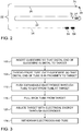
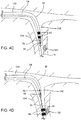
- Fig. 3 is a flowchart of steps used for ablation of tissue using probe 22, and Figs. 4A - 4D are schematic illustrations of some of the steps, according to an embodiment of the present invention.
- Figs. 4A - 4D schematically illustrate a coronary sinus 150 of heart 28, a ligament of Marshall (LOM) 154 connected to the coronary sinus, and a vein 158 through the LOM.
- LOM ligament of Marshall
- physician 36 inserts guidewire 26 into the subject, and then navigates the guidewire into heart 28.
- the guidewire is navigated via coronary sinus 150 into ligament of Marshall vein 158 until a distal end of the guidewire is distal to target region 162 (e.g., within 10 mm of the target region).
- the physician is typically assisted in the navigation by processor 44 using signals from sensor 38, or from electrode 74, to display an icon representing the location of the distal end of the guidewire on map 56.
- physician 36 may use fluoroscopy to perform the navigation.
- the intra-cardiac navigation to a difficult to access site such as LOM 154 is complicated, since guidewire 26 has to bend around one or more acute angles.
- the guidewire may need to pass through the inferior vena cava, right atrium, and coronary sinus.
- the complicated navigation is facilitated by guidewire 26 being configured to be extremely thin yet constructed to be flexible without kinking.
- step 100 The final stage of step 100 is illustrated in Fig. 4A , showing guidewire 26 within LOM vein 158.
- a tube threading step 104 the physician threads tube 32 over the guidewire, and continues the threading until a distal end of the tube is in proximity to target region 162.
- processor 44 may use signals from sensor 34 or from electrode 76 to display a representation of the tube distal end on map 56. Alternatively or additionally, the physician may use fluoroscopy to correctly locate the tube distal end.
- step 104 is illustrated in Fig. 4B , showing the distal end of tube 32 near target region 162.
- an electrode traversal step 112 the physician inserts shaft 54, with at least one expandable electrode 64 connected to the shaft distal end, into tube 32. While electrodes 64 may be compressed by the walls of the tube, they are still able to traverse the tube when the physician pushes on a proximal end of the shaft.
- the physician continues to push on the proximal end of the shaft, so continuing the traversal of electrodes 64 through tube 32, until the electrodes exit the distal end of the tube.
- the electrodes On exiting the tube distal end the electrodes may self-expand such that at least one of the electrodes contacts target region 162.
- the physician may cause the electrodes to expand distally to the distal end of tube 32 simply by pushing the electrodes from the distal end of the tube.
- the electrodes may be expanded by performing an additional, electrode-expanding step, comprising, for example, the inflation of a balloon ( Fig. 5 ).
- the electrode-expanding step may be performed between electrode traversal step 112 and first withdrawal step 116 (described below), or between first withdrawal step 116 and ablation step 120.
- the location of electrodes 64 relative to target region 162 may be verified by current tracking module 47 using impedances and/or currents between the electrodes and patches 42. Alternatively or additionally, the location of the electrodes may be verified fluoroscopically.
- a first withdrawal step 116 once electrodes 64 have exited the tube distal end and at least one of the electrodes is in contact with target region 162, the physician partially withdraws tube 32, typically by a withdrawal of approximately 1 cm, so that its distal end is no longer close to the target region.
- Fig. 4C illustrates shaft 54 and expandable electrodes 64 within tube 32, before the electrodes exit the distal end of the tube.
- Fig. 4D illustrates the state at the conclusion of step 116, i.e., when electrodes 64 have exited the distal end of tube 32, and have expanded to contact target region 162, and when the distal end of the tube has been partially withdrawn.
- the physician operates processor 44 and ablation module 66 to supply electrical current to electrodes 64.
- the supplied current may be bipolar, i.e., the current may be passed between the electrodes so as to convey ablation energy to the tissue.
- the supplied ablation energy may be unipolar, i.e., an electrical current may be applied between one of electrodes 64 and a return electrode (not shown) connected to generator 86.
- the return electrode may be disposed outside the body of patient 30; for example, the return electrode may comprise a patch coupled to the patient's body.
- RF electrical current is supplied to the electrodes, such that RF ablation of the tissue is performed.
- pulsed current may be supplied so as to perform irreversible electroporation (IRE) or pulsed field ablation (PFA).
- a second withdrawal step 124 once the physician completes the ablation in step 120, the physician may advance the tube to the electrodes, withdraw electrodes 64 into the tube, then withdraw the combination of the tube, shaft 54, and electrodes 64 from patient 30.
- the electrodes prior to withdrawing the electrodes into the tube, the electrodes may be compressed, e.g., by deflating a balloon ( Fig. 5 ). Subsequently, the guidewire may also be withdrawn.
- Fig. 3 describes the ablation of one target region.
- embodiments of the present invention are not limited to ablation of a single region, but rather may be used to ablate two or more separate regions during a single ablation procedure. For example, if there is a second target region, closer to the coronary sinus than target region 162, the electrodes may be withdrawn into the tube as described in step 124, the combination may be moved into proximity with the second region, and the electrodes may be pushed to exit from the tube distal end and expand to contact the second region in preparation for ablation of that region.
- Fig. 5 is a schematic illustration of probe 22, in accordance with some embodiments of the present invention.
- probe 22 comprises an inflatable balloon 68 coupled to the distal end of shaft 54.
- Balloon 68 comprises an electrically-conducting proximal portion 68p and an electrically-conducting distal portion 68d, along with an electrically-insulating middle portion 68m that insulates proximal portion 68p from distal portion 68d. (Typically, there are no electrodes or any other electrically-conducting elements disposed on electrically-insulating middle portion 68m.)
- the proximal and distal ends of the balloon - i.e., the proximal end of proximal portion 68p and the distal end of distal portion 68d - are bonded to the shaft.
- Balloon 68 is typically made from a polymer, such as polyurethane, with each of the proximal and distal portions of the balloon additionally comprising an electrically-conducting metallic coating (comprising gold, for example) that coats the polymer.
- an electrically-conducting metallic coating comprising gold, for example
- the coating is represented in Fig. 5 by a dotted hatch pattern.
- Conductors e.g., wires traversing the shaft connect these metallic coatings to generator 86 ( Fig. 1 ).
- the polymer may be placed into a plating bath with middle portion 68m masked.
- an electrically-charged seed layer (comprising, for example, silver, palladium, titanium tungsten, and/or titanium) may be deposited onto the polymer prior to the plating.
- each of the proximal and distal portions of the balloon is electrically-conducting over at least half of its circumference.
- the aforementioned electrically-conducting metallic coating may extend around the entire circumference of each of these portions.
- at least one of these portions may comprise multiple discrete electrodes that collectively cover at least half of the circumference of the portion.
- two electrodes may each span 150 degrees, with two 30-degree electrically-insulative gaps separating the electrodes from one another.
- Such electrodes may be formed, for example, by performing the coating procedure outlined above with the placement of additional masks over the inter-electrode gaps.
- balloon 68 is relatively elongated, so as to facilitate contacting target region 162 while disposed within a narrow lumen such as vein 158 ( Figs. 4A-D ).
- the length L of the balloon may be 2-20 times greater than the maximal cross-sectional diameter D of the balloon, which is typically between 1 and 3 mm.
- D is the diameter of middle portion 68m, or at least of the axial center thereof.
- middle portion 68m may be of a constant diameter D, with the proximal and distal portions of the balloon being of a variable diameter such that the balloon reaches its minimal diameter at the proximal and distal ends thereof.
- sensing electrodes and/or other sensors are coupled to middle portion 68m and are connected to console 24 ( Fig. 1 ) via conductors (e.g., wires) traversing the shaft.
- conductors e.g., wires
- Such sensors may be used, for example, to acquire electrophysiological signals from tissue or to measure impedance.
- the balloon further comprises an atraumatic tip 72 disposed distally to the electrically-conducting distal portion.
- Atraumatic tip 72 is typically made from a relatively soft and compressible material such as polyurethane or polyether block amide (PEBA).
- the distal end of the shaft protrudes from the balloon.
- the distal end of the shaft may comprise an atraumatic tip 73, which may be made from polyurethane, PEBA, or any other suitable material.
- the shaft may terminate proximally to the distal end of the balloon.
- probe 22 shown in Fig. 5 is typically used as described above with reference to Fig. 3 , with the electrically-conducting proximal and distal portions of the balloon functioning as expandable electrodes 64 ( Fig. 2 ).
- electric current is passed between the two electrically-conducting portions of the balloon, i.e., the ablation is bipolar.
- the balloon is shaped to define multiple apertures 70 passing through the wall of the balloon.
- a fluid-delivery tube (not shown), configured to deliver a fluid, such as saline, from a pump in console 24 ( Fig. 1 ) to the interior of the balloon, passes through shaft 54.
- the fluid may be streamed through the balloon via the fluid-delivery tube.
- the flow of the fluid through apertures 70 may also help transfer heat from the tissue and prevent coagulation of the patient's blood while electrical energy is conveyed to the tissue.
Landscapes
- Health & Medical Sciences (AREA)
- Surgery (AREA)
- Engineering & Computer Science (AREA)
- Life Sciences & Earth Sciences (AREA)
- Biomedical Technology (AREA)
- Molecular Biology (AREA)
- Nuclear Medicine, Radiotherapy & Molecular Imaging (AREA)
- Plasma & Fusion (AREA)
- Physics & Mathematics (AREA)
- Heart & Thoracic Surgery (AREA)
- Medical Informatics (AREA)
- Otolaryngology (AREA)
- Animal Behavior & Ethology (AREA)
- General Health & Medical Sciences (AREA)
- Public Health (AREA)
- Veterinary Medicine (AREA)
- Cardiology (AREA)
- Surgical Instruments (AREA)
Abstract
Description
- The present invention relates to the ablation of tissue.
- The ligament of Marshall (LOM), which is located on the epicardium between the left atrial appendage and the left pulmonary veins, is often a source of paroxysmal atrial fibrillation.
- Radio-frequency (RF) ablation and irreversible electroporation (IRE) are leading modalities for ablating cardiac tissue, e.g., for treating atrial fibrillation.
-
US Patent 9,655,677 - There is provided, in accordance with some embodiments of the present invention, an apparatus including a shaft and an inflatable balloon coupled to a distal end of the shaft. The balloon includes a proximal portion that is electrically-conducting over at least half of a proximal-portion circumference of the proximal portion, a distal portion that is electrically-conducting over at least half of a distal-portion circumference of the distal portion, and an electrically-insulating middle portion that insulates the proximal portion from the distal portion.
- In some embodiments, a length of the balloon is 2-20 times greater than a maximal cross-sectional diameter of the balloon.
- In some embodiments, the balloon is shaped to define multiple apertures passing through a wall of the balloon.
- In some embodiments, the balloon further includes an atraumatic tip disposed distally to the electrically-conducting distal portion.
- In some embodiments, the distal end of the shaft protrudes from the balloon.
- In some embodiments, no electrically-conducting element is disposed on the electrically-insulating middle portion.
- There is further provided, in accordance with some embodiments of the present invention, a probe, including a guidewire configured to access tissue of a human subject by traversing a lumen of the tissue. The probe further includes a tube, dimensioned to access and penetrate into the lumen while being threaded over the guidewire, the tube being shaped to define a tube lumen. The probe further includes a plurality of expandable electrodes configured to traverse the tube lumen, to expand distally to a distal end of the tube subsequently to traversing the tube lumen, and to convey ablation energy to the tissue, by virtue of electrical current passing between the electrodes, while at least one of the expanded electrodes contacts the tissue.
- In some embodiments, the expandable electrodes are configured to convey the ablation energy without permanent deformation of any of the electrodes.
- In some embodiments, the probe further includes a shaft having a distal end connected to the expandable electrodes.
- In some embodiments, the shaft includes at least one conductor configured to transfer the electrical current to the electrodes without permanent damage to the at least one conductor.
- In some embodiments, the expandable electrodes include an electrically-conducting proximal portion of an inflatable balloon and an electrically-conducting distal portion of the inflatable balloon, which are configured to expand upon inflation of the inflatable balloon.
- In some embodiments, the tissue includes a ligament of Marshall.
- There is further provided, in accordance with some embodiments of the present invention, a method for ablating tissue of a human subject. The method includes inserting a guidewire into a lumen of the human subject. The method further includes threading a tube over the guidewire, the tube being dimensioned to penetrate the lumen so that a distal end of the tube is in proximity to a target region to be ablated. The method further includes, after threading the tube over the guidewire, traversing a plurality of expandable electrodes through the tube. The method further includes, subsequently to traversing the expandable electrodes through the tube, causing the expandable electrodes to expand distally to the distal end of the tube such that at least one of the expandable electrodes contacts the target region to be ablated. The method further includes, by passing electrical current between the expandable electrodes, conveying electrical energy to the contacted target region so as to ablate the target region.
- In some embodiments, conveying the electrical energy includes conveying the electrical energy without permanent deformation of any of the expandable electrodes.
- In some embodiments, causing the expandable electrodes to expand distally to the distal end of the tube includes causing the expandable electrodes to expand by pushing the expandable electrodes from the distal end of the tube.
- In some embodiments, the expandable electrodes are connected to a distal end of a shaft, and traversing the expandable electrodes through the tube includes using the shaft to traverse the expandable electrodes through the tube.
- In some embodiments, the shaft includes at least one conductor configured to transfer the electrical current to the electrodes without permanent damage to the at least one conductor.
- In some embodiments, the tissue includes a ligament of Marshall.
- In some embodiments, conveying the electrical energy includes conveying the electrical energy so as to irreversibly electroporate the target region.
- In some embodiments,
the expandable electrodes include an electrically-conducting proximal portion of an inflatable balloon and an electrically-conducting distal portion of the inflatable balloon, and
causing the expandable electrodes to expand includes causing the expandable electrodes to expand by inflating the balloon. - In some embodiments, a length of the balloon is 2-20 times greater than a maximal cross-sectional diameter of the balloon.
- In some embodiments, the balloon is shaped to define multiple apertures passing through a wall of the balloon, and the method further includes, while conveying the electrical energy, passing a fluid through the apertures.
- The present invention will be more fully understood from the following detailed description of embodiments thereof, taken together with the drawings, in which:
-
-
Fig. 1 is a schematic, pictorial illustration of a medical system, according to an embodiment of the present invention; -
Fig. 2 is a schematic pictorial illustration of elements of a medical probe used in the system, according to an embodiment of the present invention; -
Fig. 3 is a flowchart of steps used for ablation of tissue using the medical probe, according to an embodiment of the present invention; -
Figs. 4A - 4D are schematic illustrations of some of the steps of the flowchart, according to an embodiment of the present invention; and -
Fig. 5 is a schematic illustration of a medical probe, in accordance with some embodiments of the present invention. - Many regions of the heart are accessed endocardially relatively easily, and so are amenable to ablation by conventional catheters, such as a focal catheter or a balloon catheter. However, there are certain regions of the heart, such as the ligament of Marshall, that are difficult to access endocardially, typically because a possible endocardial path is tortuous, comprising one or more relatively acute angular bends that a conventional catheter is unable to traverse. While these regions may in some cases be accessed epicardially, endocardial access is preferred.
- To address this challenge, the inventors have developed apparatuses and methods for endocardially accessing difficult-to-reach regions of a patient's anatomy, and the description herein is provided by way of example for one such region, the ligament of Marshall. The description may be modified, mutatis mutandis, for other difficult-to-reach regions.
- In an embodiment of the present invention a medical probe comprises three elements: a flexible guidewire, a tube that is configured to thread over the guidewire, and a shaft, having one or more (typically, two or more) expandable electrodes, at a distal end of the shaft, that may traverse the tube. In contrast to the conventional catheters referred to above, which cannot access the difficult-to-reach regions, the probe is able to access the regions, by virtue of its narrow width and flexibility.
- The guidewire is navigated to a region targeted for ablation, and then the tube of the probe is threaded over the guidewire, until a distal end of the tube is in proximity to the target region. The shaft with its expandable electrodes is then pushed into the tube, and is pushed until the expandable electrodes exit the tube distal end, at which point the electrodes expand such that at least one of the electrodes contacts the target region. (Thus, the tube guides the expandable electrodes along the desired path to the target region.) Subsequently, the expanded electrodes may be used to ablate the target region, typically by passing bipolar electrical current between the electrodes.
- Advantageously, the electrodes are large enough to transfer electrical current for ablation without being irreparably damaged. In addition, the shaft is large enough to support conductors that are undamaged by the electrical current transfer.
- In some embodiments, the electrodes are self-expanding by virtue of being formed from a shape-memory material. In other embodiments, the electrodes are actively expanded. For example, an inflatable balloon may be coupled to the distal end of the shaft, the surface of the balloon being coated with a suitable metallic material so as to define two electrodes. To expand the electrodes, the balloon may be inflated.
-
Fig. 1 is a schematic, pictorial illustration of amedical system 20 comprising amedical probe 22 and acontrol console 24, andFig. 2 is a schematic pictorial illustration of elements of the medical probe, according to an embodiment of the present invention.Medical system 20 may be based, for example, on the CARTO® system, produced by Biosense Webster Inc. of 31 Technology Drive, Irvine, CA 92618 USA.Probe 22 is used as a catheter, and is also referred to herein ascatheter 22. -
Fig. 1 illustrates aphysician 36 using ahandle 80 to controlprobe 22. In embodiments described hereinbelow,probe 22 is used for ablation of tissue in aheart 28 of a patient 30 (also referred to herein as a subject). Typically,probe 22 is used to ablate elements of the heart that are difficult to access, and by way of example, ablation of a portion of a ligament of Marshall ofheart 28 is described herein. However, it will be understood thatmedical probe 22 may be used, mutatis mutandis, for other therapeutic and/or diagnostic purposes in the heart or in other body organs. - As shown in
Fig. 2 ,probe 22 comprises aflexible guidewire 26, aflexible tube 32, and aflexible shaft 54. -
Guidewire 26 is typically bent at its distal end, as illustrated, and typically comprises alocation sensor 38, comprising at least one coil, at the distal end. Alternatively or additionally, guidewire 26 typically has at least oneelectrode 74, at its distal end, which may also be used for sensing location. In oneembodiment guidewire 26 is formed as a stainless steel coil having a diameter of approximately 325 microns, and conductors forsensor 38 and/orelectrode 74 traverse a lumen of the coil. -
Flexible tube 32 typically also has alocation sensor 34, comprising at least one coil, at its distal end. Alternatively or additionally,tube 32 typically has at least oneelectrode 76, at its distal end, which may be used for sensing location.Tube 32 is dimensioned to have an internal diameter permitting it to thread overguidewire 26, and an external diameter of approximately 1 mm, permitting it to enter a vein or other body of the order of 1 mm in diameter.Tube 32 may be constructed from any stable biocompatible plastic which may be formed with these dimensions. Conductors forsensor 34 and/orelectrode 76 may be formed within a wall oftube 32. -
Flexible shaft 54 is typically formed as a braided tube (made of polyimide, for example), the braiding resisting any tendency of the shaft to kink. At the distal end of the shaft are one or more (typically, two or more)expandable electrodes 64.Electrodes 64 are configured to be large enough to convey ablation energy to tissue that contacts the electrodes, without the electrodes permanently deforming. Similarly, conductors connected to the electrodes, configured to convey the ablation energy, traverse the shaft and are dimensioned to be large enough to convey the ablation energy without permanent deformation. - Each of
electrodes 64 is described herein as being "expandable," in that the electrode may expand, upon exitingtube 32, from a radially-compressed configuration, which the electrode assumes while inside oftube 32, to a radially-expanded configuration. In some embodiments, each electrode is formed from a shape-memory material such as Nitinol (optionally coated with a biocompatible material such as gold), such that the electrode expands due to the shape-memory effect, i.e., the electrode is self-expanding. In other embodiments, the electrodes are actively expanded by the application of electrical and/or mechanical energy. Such energy may be applied byphysician 36 or by processor 44 (described below), optionally in response to an input from the physician. In the context of the present application, including the claims, the term "expandable electrode" includes both a self-expanding electrode and an electrode that is not self-expanding. - In general, each of
electrodes 64 may have any suitable form. For example, as shown inFig. 2 , each electrode may have a helical or helicoid configuration. Alternatively, each electrode may comprise a basket of circumferentially-distributed spines disposed over the shaft. In such embodiments, the electrode may be self-expanding, or the expansion may be effected by the pulling of a pull wire coupled to the basket so as to retract the distal end of the basket towards the proximal end of the basket. In yet other embodiments, as described below with reference toFig. 5 , each ofelectrodes 64 comprises a coated portion of an inflatable balloon, such that the electrodes expand upon inflation of the balloon. - In the configuration shown in
Figure 1 , acontrol console 24 is connected, by acable 40, to body surface electrodes, which typically compriseadhesive skin patches 42 that are affixed topatient 30.Control console 24 also comprises a processor 44 which is coupled to a number of modules, the modules comprising software and/or hardware components. Details and functionality of the modules are described below. - Processor 44 determines location coordinates, i.e., position coordinates and orientation coordinates, of the distal ends of
guidewire 26 andtube 32 based on signals received respectively fromsensors module 88. The sensors generate their signals in response to magnetic fields, transmitted by alternatingmagnetic field radiators 78 positioned beneathpatient 30, traversing the sensors. - Alternatively or additionally, processor 44, in conjunction with a
current tracking module 46, determines location coordinates of the distal ends ofguidewire 26 and/ortube 32 insideheart 28 based on impedances and/or currents measured betweenadhesive skin patches 42 andelectrodes electrodes heart 28. - Processor 44 may comprise real-time
noise reduction circuitry 50 typically configured as a field programmable gate array (FPGA), followed by an analog-to-digital (A/D) signal conversion integratedcircuit 52. The processor can pass the signals from A/D circuit 52 to another processor and/or can be programmed to determine the location coordinates referred to above. - Impedance and current-based location tracking techniques are described, for example, in
U.S. Patents 5,983,126 ,6,456,864 , and5,944,022 . Electromagnetic location tracking techniques are described, for example, inU.S. Patents 5,391,199 ,6,690,963 , and6,892,091 . The methods of location sensing described hereinabove are implemented in the above-mentioned CARTO® system and are described in detail in the patents cited above, the respective disclosures of which are incorporated herein by reference. - Prior to insertion of elements of
probe 22 intopatient 30, processor 44 acquires anelectroanatomical map 56 ofheart 28. Typically data for the map is acquired using a probe other thanprobe 22, such as a focal catheter which is configured to be both tracked bymodule 46 and to acquire signals from regions of heart chambers contacted by the catheter. Typically, although not necessarily, processor 44 uses the signals to determine local activation times (LATs) of the heart chambers, and incorporates the LATs intomap 56.Map 56 is stored in amemory 60 accessible by processor 44, and during the procedure the processor can presentmap 56 tophysician 36 on adisplay 58. - During the
procedure using probe 22, processor 44 may overlay an icon, representing the location of the distal ends referred to above, onmap 56, so enablingphysician 36 to track the distal ends. -
Memory 60 may comprise any suitable volatile and/or nonvolatile memory, such as random access memory or a hard disk drive. In some embodiments,physician 36 can manipulate map 56 using one ormore input devices 62. In alternative embodiments,display 58 may comprise a touchscreen that can be configured to accept inputs fromphysician 36, in addition to presentingmap 56. -
Control console 24 also comprises an ablation module 66. Ablation module 66 is configured to monitor and control ablation parameters such as the level and the duration of ablation power (e.g., radio-frequency (RF) energy) conveyed toelectrodes 64 from ablation module 66, and module 66 typically comprises agenerator 86, such as an RF generator, for this purpose. -
Fig. 3 is a flowchart of steps used for ablation oftissue using probe 22, andFigs. 4A - 4D are schematic illustrations of some of the steps, according to an embodiment of the present invention.Figs. 4A - 4D schematically illustrate acoronary sinus 150 ofheart 28, a ligament of Marshall (LOM) 154 connected to the coronary sinus, and avein 158 through the LOM. The following description assumes, by way of example, that atarget region 162 ofLOM 154 is to be ablated. - In an
initial step 100,physician 36 inserts guidewire 26 into the subject, and then navigates the guidewire intoheart 28. Within the heart, the guidewire is navigated viacoronary sinus 150 into ligament ofMarshall vein 158 until a distal end of the guidewire is distal to target region 162 (e.g., within 10 mm of the target region). The physician is typically assisted in the navigation by processor 44 using signals fromsensor 38, or fromelectrode 74, to display an icon representing the location of the distal end of the guidewire onmap 56. Alternatively or additionallyphysician 36 may use fluoroscopy to perform the navigation. - It will be understood that the intra-cardiac navigation to a difficult to access site such as
LOM 154 is complicated, sinceguidewire 26 has to bend around one or more acute angles. For example, to reach the LOM, the guidewire may need to pass through the inferior vena cava, right atrium, and coronary sinus. The complicated navigation is facilitated byguidewire 26 being configured to be extremely thin yet constructed to be flexible without kinking. - The final stage of
step 100 is illustrated inFig. 4A , showingguidewire 26 withinLOM vein 158. - Once
physician 36 has satisfactorily navigated the distal end of the guidewire to be distal to targetregion 162, in atube threading step 104 thephysician threads tube 32 over the guidewire, and continues the threading until a distal end of the tube is in proximity to targetregion 162. To assist the physician in correctly locating the distal end of the tube, processor 44 may use signals fromsensor 34 or fromelectrode 76 to display a representation of the tube distal end onmap 56. Alternatively or additionally, the physician may use fluoroscopy to correctly locate the tube distal end. - The final stage of
step 104 is illustrated inFig. 4B , showing the distal end oftube 32 neartarget region 162. - In an
electrode traversal step 112, the physician insertsshaft 54, with at least oneexpandable electrode 64 connected to the shaft distal end, intotube 32. Whileelectrodes 64 may be compressed by the walls of the tube, they are still able to traverse the tube when the physician pushes on a proximal end of the shaft. - The physician continues to push on the proximal end of the shaft, so continuing the traversal of
electrodes 64 throughtube 32, until the electrodes exit the distal end of the tube. On exiting the tube distal end the electrodes may self-expand such that at least one of the electrodes contacts targetregion 162. In other words, provided the electrodes are self-expanding, the physician may cause the electrodes to expand distally to the distal end oftube 32 simply by pushing the electrodes from the distal end of the tube. In the event that the electrodes are not self-expanding, the electrodes may be expanded by performing an additional, electrode-expanding step, comprising, for example, the inflation of a balloon (Fig. 5 ). The electrode-expanding step may be performed betweenelectrode traversal step 112 and first withdrawal step 116 (described below), or betweenfirst withdrawal step 116 andablation step 120. - In an embodiment of the invention the location of
electrodes 64 relative to targetregion 162 may be verified by current tracking module 47 using impedances and/or currents between the electrodes andpatches 42. Alternatively or additionally, the location of the electrodes may be verified fluoroscopically. - In a
first withdrawal step 116, onceelectrodes 64 have exited the tube distal end and at least one of the electrodes is in contact withtarget region 162, the physician partially withdrawstube 32, typically by a withdrawal of approximately 1 cm, so that its distal end is no longer close to the target region. -
Fig. 4C illustratesshaft 54 andexpandable electrodes 64 withintube 32, before the electrodes exit the distal end of the tube.Fig. 4D illustrates the state at the conclusion ofstep 116, i.e., whenelectrodes 64 have exited the distal end oftube 32, and have expanded to contacttarget region 162, and when the distal end of the tube has been partially withdrawn. - In an
ablation step 120 the physician operates processor 44 and ablation module 66 to supply electrical current toelectrodes 64. If there are two ormore electrodes 64, then the supplied current may be bipolar, i.e., the current may be passed between the electrodes so as to convey ablation energy to the tissue. Alternatively (e.g., if there is only one electrode 64), the supplied ablation energy may be unipolar, i.e., an electrical current may be applied between one ofelectrodes 64 and a return electrode (not shown) connected togenerator 86. The return electrode may be disposed outside the body ofpatient 30; for example, the return electrode may comprise a patch coupled to the patient's body. - In some embodiments, RF electrical current is supplied to the electrodes, such that RF ablation of the tissue is performed. Alternatively, pulsed current may be supplied so as to perform irreversible electroporation (IRE) or pulsed field ablation (PFA).
- In a
second withdrawal step 124, once the physician completes the ablation instep 120, the physician may advance the tube to the electrodes, withdrawelectrodes 64 into the tube, then withdraw the combination of the tube,shaft 54, andelectrodes 64 frompatient 30. In some embodiments, prior to withdrawing the electrodes into the tube, the electrodes may be compressed, e.g., by deflating a balloon (Fig. 5 ). Subsequently, the guidewire may also be withdrawn. - The flowchart of
Fig. 3 describes the ablation of one target region. However, embodiments of the present invention are not limited to ablation of a single region, but rather may be used to ablate two or more separate regions during a single ablation procedure. For example, if there is a second target region, closer to the coronary sinus thantarget region 162, the electrodes may be withdrawn into the tube as described instep 124, the combination may be moved into proximity with the second region, and the electrodes may be pushed to exit from the tube distal end and expand to contact the second region in preparation for ablation of that region. - Reference is now made to
Fig. 5 , which is a schematic illustration ofprobe 22, in accordance with some embodiments of the present invention. - In some embodiments,
probe 22 comprises aninflatable balloon 68 coupled to the distal end ofshaft 54.Balloon 68 comprises an electrically-conductingproximal portion 68p and an electrically-conductingdistal portion 68d, along with an electrically-insulatingmiddle portion 68m that insulatesproximal portion 68p fromdistal portion 68d. (Typically, there are no electrodes or any other electrically-conducting elements disposed on electrically-insulatingmiddle portion 68m.) The proximal and distal ends of the balloon - i.e., the proximal end ofproximal portion 68p and the distal end ofdistal portion 68d - are bonded to the shaft. -
Balloon 68 is typically made from a polymer, such as polyurethane, with each of the proximal and distal portions of the balloon additionally comprising an electrically-conducting metallic coating (comprising gold, for example) that coats the polymer. (The coating is represented inFig. 5 by a dotted hatch pattern.) Conductors (e.g., wires) traversing the shaft connect these metallic coatings to generator 86 (Fig. 1 ). - To coat the proximal and distal portions of the polymer, the polymer may be placed into a plating bath with
middle portion 68m masked. To facilitate the plating, an electrically-charged seed layer (comprising, for example, silver, palladium, titanium tungsten, and/or titanium) may be deposited onto the polymer prior to the plating. - Typically, for increased contact with the target region, each of the proximal and distal portions of the balloon is electrically-conducting over at least half of its circumference. For example, the aforementioned electrically-conducting metallic coating may extend around the entire circumference of each of these portions. Alternatively, at least one of these portions may comprise multiple discrete electrodes that collectively cover at least half of the circumference of the portion. As a purely illustrative example, two electrodes may each span 150 degrees, with two 30-degree electrically-insulative gaps separating the electrodes from one another. Such electrodes may be formed, for example, by performing the coating procedure outlined above with the placement of additional masks over the inter-electrode gaps.
- Typically,
balloon 68 is relatively elongated, so as to facilitate contactingtarget region 162 while disposed within a narrow lumen such as vein 158 (Figs. 4A-D ). For example, the length L of the balloon may be 2-20 times greater than the maximal cross-sectional diameter D of the balloon, which is typically between 1 and 3 mm. (Typically, D is the diameter ofmiddle portion 68m, or at least of the axial center thereof. For example,middle portion 68m may be of a constant diameter D, with the proximal and distal portions of the balloon being of a variable diameter such that the balloon reaches its minimal diameter at the proximal and distal ends thereof.) - In some embodiments, sensing electrodes and/or other sensors are coupled to
middle portion 68m and are connected to console 24 (Fig. 1 ) via conductors (e.g., wires) traversing the shaft. Such sensors may be used, for example, to acquire electrophysiological signals from tissue or to measure impedance. - In some embodiments, the balloon further comprises an
atraumatic tip 72 disposed distally to the electrically-conducting distal portion.Atraumatic tip 72 is typically made from a relatively soft and compressible material such as polyurethane or polyether block amide (PEBA). - In some embodiments, as shown in
Fig. 5 , the distal end of the shaft protrudes from the balloon. The distal end of the shaft may comprise anatraumatic tip 73, which may be made from polyurethane, PEBA, or any other suitable material. In other embodiments - particularly those in which the balloon comprises atraumatic tip 72 - the shaft may terminate proximally to the distal end of the balloon. - The embodiment of
probe 22 shown inFig. 5 is typically used as described above with reference toFig. 3 , with the electrically-conducting proximal and distal portions of the balloon functioning as expandable electrodes 64 (Fig. 2 ). Typically, electric current is passed between the two electrically-conducting portions of the balloon, i.e., the ablation is bipolar. - Typically, the balloon is shaped to define
multiple apertures 70 passing through the wall of the balloon. A fluid-delivery tube (not shown), configured to deliver a fluid, such as saline, from a pump in console 24 (Fig. 1 ) to the interior of the balloon, passes throughshaft 54. To inflate the balloon (and subsequently keep the balloon inflated during the ablation procedure), the fluid may be streamed through the balloon via the fluid-delivery tube. The flow of the fluid throughapertures 70 may also help transfer heat from the tissue and prevent coagulation of the patient's blood while electrical energy is conveyed to the tissue. - It will be appreciated by persons skilled in the art that the present invention is not limited to what has been particularly shown and described hereinabove. Rather, the scope of embodiments of the present invention includes both combinations and subcombinations of the various features described hereinabove, as well as variations and modifications thereof that are not in the prior art, which would occur to persons skilled in the art upon reading the foregoing description. Documents incorporated by reference in the present patent application are to be considered an integral part of the application except that to the extent any terms are defined in these incorporated documents in a manner that conflicts with the definitions made explicitly or implicitly in the present specification, only the definitions in the present specification should be considered.
-
- 1. A method for ablating tissue of a human subject, the method comprising:
- inserting a guidewire into a lumen of the human subject;
- threading a tube over the guidewire, the tube being dimensioned to penetrate the lumen so that a distal end of the tube is in proximity to a target region to be ablated;
- after threading the tube over the guidewire, traversing a plurality of expandable electrodes through the tube;
- subsequently to traversing the expandable electrodes through the tube, causing the expandable electrodes to expand distally to the distal end of the tube such that at least one of the expandable electrodes contacts the target region to be ablated; and
- by passing electrical current between the expandable electrodes, conveying electrical energy to the contacted target region so as to ablate the target region.
- 2. The method according to
aspect 1, wherein conveying the electrical energy comprises conveying the electrical energy without permanent deformation of any of the expandable electrodes. - 3. The method according to
aspect 1, wherein causing the expandable electrodes to expand distally to the distal end of the tube comprises causing the expandable electrodes to expand by pushing the expandable electrodes from the distal end of the tube. - 4. The method according to
aspect 1, wherein the expandable electrodes are connected to a distal end of a shaft, and wherein traversing the expandable electrodes through the tube comprises using the shaft to traverse the expandable electrodes through the tube. - 5. The method according to aspect 4, wherein the shaft includes at least one conductor configured to transfer the electrical current to the electrodes without permanent damage to the at least one conductor.
- 6. The method according to
aspect 1, wherein the tissue includes a ligament of Marshall. - 7. The method according to
aspect 1, wherein conveying the electrical energy comprises conveying the electrical energy so as to irreversibly electroporate the target region. - 8. The method according to
aspect 1,
wherein the expandable electrodes include an electrically-conducting proximal portion of an inflatable balloon and an electrically-conducting distal portion of the inflatable balloon, and
wherein causing the expandable electrodes to expand comprises causing the expandable electrodes to expand by inflating the balloon. - 9. The method according to aspect 8, wherein a length of the balloon is 2-20 times greater than a maximal cross-sectional diameter of the balloon.
- 10. The method according to aspect 8, wherein the balloon is shaped to define multiple apertures passing through a wall of the balloon, and wherein the method further comprises, while conveying the electrical energy, passing a fluid through the apertures.
Claims (12)
- Apparatus, comprising:a shaft; andan inflatable balloon coupled to a distal end of the shaft, the balloon comprising:a proximal portion that is electrically-conducting over at least half of a proximal-portion circumference of the proximal portion;a distal portion that is electrically-conducting over at least half of a distal-portion circumference of the distal portion; andan electrically-insulating middle portion that insulates the proximal portion from the distal portion.
- The apparatus according to claim 1, wherein a length of the balloon is 2-20 times greater than a maximal cross-sectional diameter of the balloon.
- The apparatus according to claim 1, wherein the balloon is shaped to define multiple apertures passing through a wall of the balloon.
- The apparatus according to claim 1, wherein the balloon further comprises an atraumatic tip disposed distally to the electrically-conducting distal portion.
- The apparatus according to claim 1, wherein the distal end of the shaft protrudes from the balloon.
- The apparatus according to claim 1, wherein no electrically-conducting element is disposed on the electrically-insulating middle portion.
- A probe, comprising:a guidewire configured to access tissue of a human subject by traversing a lumen of the tissue;a tube, dimensioned to access and penetrate into the lumen while being threaded over the guidewire, the tube being shaped to define a tube lumen; anda plurality of expandable electrodes configured to:traverse the tube lumen,subsequently to traversing the tube lumen, expand distally to a distal end of the tube, andwhile at least one of the expanded electrodes contacts the tissue, convey ablation energy to the tissue by virtue of electrical current passing between the electrodes.
- The probe according to claim 7, wherein the expandable electrodes are configured to convey the ablation energy without permanent deformation of any of the electrodes.
- The probe according to claim 7, further comprising a shaft having a distal end connected to the expandable electrodes.
- The probe according to claim 9, wherein the shaft comprises at least one conductor configured to transfer the electrical current to the electrodes without permanent damage to the at least one conductor.
- The probe according to claim 9, wherein the expandable electrodes comprise an electrically-conducting proximal portion of an inflatable balloon and an electrically-conducting distal portion of the inflatable balloon, which are configured to expand upon inflation of the inflatable balloon.
- The probe according to claim 7, wherein the tissue includes a ligament of Marshall.
Applications Claiming Priority (3)
| Application Number | Priority Date | Filing Date | Title |
|---|---|---|---|
| US202063013957P | 2020-04-22 | 2020-04-22 | |
| US202063131466P | 2020-12-29 | 2020-12-29 | |
| US17/197,870 US20210330372A1 (en) | 2020-04-22 | 2021-03-10 | Ablation of a hard-to-access region |
Publications (1)
| Publication Number | Publication Date |
|---|---|
| EP3900659A1 true EP3900659A1 (en) | 2021-10-27 |
Family
ID=75625447
Family Applications (1)
| Application Number | Title | Priority Date | Filing Date |
|---|---|---|---|
| EP21169582.0A Pending EP3900659A1 (en) | 2020-04-22 | 2021-04-21 | Ablation of a hard-to-access region |
Country Status (5)
| Country | Link |
|---|---|
| US (1) | US20210330372A1 (en) |
| EP (1) | EP3900659A1 (en) |
| JP (1) | JP2021171650A (en) |
| CN (1) | CN113520579A (en) |
| IL (1) | IL282271A (en) |
Cited By (1)
| Publication number | Priority date | Publication date | Assignee | Title |
|---|---|---|---|---|
| US12076071B2 (en) | 2020-08-14 | 2024-09-03 | Kardium Inc. | Systems and methods for treating tissue with pulsed field ablation |
Families Citing this family (1)
| Publication number | Priority date | Publication date | Assignee | Title |
|---|---|---|---|---|
| WO2024024173A1 (en) * | 2022-07-26 | 2024-02-01 | 株式会社ヨコオ | Catheter, medical care system and operation method of catheter |
Citations (10)
| Publication number | Priority date | Publication date | Assignee | Title |
|---|---|---|---|---|
| US5391199A (en) | 1993-07-20 | 1995-02-21 | Biosense, Inc. | Apparatus and method for treating cardiac arrhythmias |
| US5944022A (en) | 1997-04-28 | 1999-08-31 | American Cardiac Ablation Co. Inc. | Catheter positioning system |
| US5983126A (en) | 1995-11-22 | 1999-11-09 | Medtronic, Inc. | Catheter location system and method |
| US6456864B1 (en) | 1994-10-11 | 2002-09-24 | Ep Technologies, Inc. | Systems and methods for guiding movable electrode elements within multiple-electrode structures |
| WO2002094115A2 (en) * | 2001-05-24 | 2002-11-28 | Cardiac Pacemakers, Inc. | Twin coaxial catheters for rf pulmonary vein ablation |
| US6690963B2 (en) | 1995-01-24 | 2004-02-10 | Biosense, Inc. | System for determining the location and orientation of an invasive medical instrument |
| US6892091B1 (en) | 2000-02-18 | 2005-05-10 | Biosense, Inc. | Catheter, method and apparatus for generating an electrical map of a chamber of the heart |
| US20150112328A1 (en) * | 2013-10-18 | 2015-04-23 | Boston Scientific Scimed, Inc. | Balloon catheters with flexible conducting wires and related methods of use and manufacture |
| US9655677B2 (en) | 2010-05-12 | 2017-05-23 | Shifamed Holdings, Llc | Ablation catheters including a balloon and electrodes |
| EP3381396A1 (en) * | 2017-03-31 | 2018-10-03 | Biosense Webster (Israel) Ltd. | Balloon catheter with large area electrodes |
Family Cites Families (8)
| Publication number | Priority date | Publication date | Assignee | Title |
|---|---|---|---|---|
| CA2165829A1 (en) * | 1993-07-01 | 1995-01-19 | John E. Abele | Imaging, electrical potential sensing, and ablation catheters |
| US6012457A (en) * | 1997-07-08 | 2000-01-11 | The Regents Of The University Of California | Device and method for forming a circumferential conduction block in a pulmonary vein |
| US20040106952A1 (en) * | 2002-12-03 | 2004-06-03 | Lafontaine Daniel M. | Treating arrhythmias by altering properties of tissue |
| WO2009121009A2 (en) * | 2008-03-27 | 2009-10-01 | The Regents Of The University Of California | Irreversible electroporation device for use in attenuating neointimal |
| CA2743140A1 (en) * | 2008-11-11 | 2010-05-20 | Shifamed, Llc | Low profile electrode assembly |
| US20150105659A1 (en) * | 2008-11-11 | 2015-04-16 | Covidien Lp | Energy delivery device and methods of use |
| EP2568905A4 (en) * | 2010-05-12 | 2017-07-26 | Shifamed Holdings, LLC | Low profile electrode assembly |
| WO2016181316A1 (en) * | 2015-05-12 | 2016-11-17 | Navix International Limited | Systems and methods for tracking an intrabody catheter |
-
2021
- 2021-03-10 US US17/197,870 patent/US20210330372A1/en active Pending
- 2021-04-12 IL IL282271A patent/IL282271A/en unknown
- 2021-04-21 JP JP2021071678A patent/JP2021171650A/en active Pending
- 2021-04-21 EP EP21169582.0A patent/EP3900659A1/en active Pending
- 2021-04-22 CN CN202110437137.3A patent/CN113520579A/en active Pending
Patent Citations (10)
| Publication number | Priority date | Publication date | Assignee | Title |
|---|---|---|---|---|
| US5391199A (en) | 1993-07-20 | 1995-02-21 | Biosense, Inc. | Apparatus and method for treating cardiac arrhythmias |
| US6456864B1 (en) | 1994-10-11 | 2002-09-24 | Ep Technologies, Inc. | Systems and methods for guiding movable electrode elements within multiple-electrode structures |
| US6690963B2 (en) | 1995-01-24 | 2004-02-10 | Biosense, Inc. | System for determining the location and orientation of an invasive medical instrument |
| US5983126A (en) | 1995-11-22 | 1999-11-09 | Medtronic, Inc. | Catheter location system and method |
| US5944022A (en) | 1997-04-28 | 1999-08-31 | American Cardiac Ablation Co. Inc. | Catheter positioning system |
| US6892091B1 (en) | 2000-02-18 | 2005-05-10 | Biosense, Inc. | Catheter, method and apparatus for generating an electrical map of a chamber of the heart |
| WO2002094115A2 (en) * | 2001-05-24 | 2002-11-28 | Cardiac Pacemakers, Inc. | Twin coaxial catheters for rf pulmonary vein ablation |
| US9655677B2 (en) | 2010-05-12 | 2017-05-23 | Shifamed Holdings, Llc | Ablation catheters including a balloon and electrodes |
| US20150112328A1 (en) * | 2013-10-18 | 2015-04-23 | Boston Scientific Scimed, Inc. | Balloon catheters with flexible conducting wires and related methods of use and manufacture |
| EP3381396A1 (en) * | 2017-03-31 | 2018-10-03 | Biosense Webster (Israel) Ltd. | Balloon catheter with large area electrodes |
Cited By (1)
| Publication number | Priority date | Publication date | Assignee | Title |
|---|---|---|---|---|
| US12076071B2 (en) | 2020-08-14 | 2024-09-03 | Kardium Inc. | Systems and methods for treating tissue with pulsed field ablation |
Also Published As
| Publication number | Publication date |
|---|---|
| CN113520579A (en) | 2021-10-22 |
| JP2021171650A (en) | 2021-11-01 |
| IL282271A (en) | 2021-10-31 |
| US20210330372A1 (en) | 2021-10-28 |
Similar Documents
| Publication | Publication Date | Title |
|---|---|---|
| US11553961B2 (en) | Catheter with stretchable irrigation tube | |
| US20220096153A1 (en) | Catheter apparatuses for modulation of nerves in communication with the pulmonary system and associated systems and methods | |
| CN105615993B (en) | Catheter with soft distal tip for mapping and ablating tubular regions | |
| US9101374B1 (en) | Method for guiding an ablation catheter based on real time intracardiac electrical signals and apparatus for performing the method | |
| US6972016B2 (en) | Helically shaped electrophysiology catheter | |
| JP2022528810A (en) | Electrode configuration for arrhythmia diagnosis | |
| US20100191232A1 (en) | Catheters and methods for performing electrophysiological interventions | |
| JP2016144642A (en) | Basket catheter with far-field electrode | |
| JP2017192721A (en) | Basket catheter with prestrained framework | |
| CN109567787B (en) | Highlighting area for re-ablation | |
| EP3900659A1 (en) | Ablation of a hard-to-access region | |
| CN111683616A (en) | Balloon catheter with inner distal end | |
| US20240008920A1 (en) | Basket catheter with balloon | |
| US20240225726A1 (en) | Basket catheter having insulated ablation electrodes and diagnostic electrodes | |
| EP3977954A1 (en) | Basket catheter having insulated ablation electrodes | |
| US20230200896A1 (en) | Catheter balloon having increased resilience to internal pressurization | |
| EP4197473A1 (en) | Basket catheter with cushioning porous sheath cover | |
| US20220047325A1 (en) | Balloon probe for irreversible electroporation | |
| CN113081233A (en) | Lasso catheter with balloon | |
| CN118267082A (en) | Basket catheter with compatible irrigation and interleaving electrodes |
Legal Events
| Date | Code | Title | Description |
|---|---|---|---|
| PUAI | Public reference made under article 153(3) epc to a published international application that has entered the european phase |
Free format text: ORIGINAL CODE: 0009012 |
|
| STAA | Information on the status of an ep patent application or granted ep patent |
Free format text: STATUS: THE APPLICATION HAS BEEN PUBLISHED |
|
| AK | Designated contracting states |
Kind code of ref document: A1 Designated state(s): AL AT BE BG CH CY CZ DE DK EE ES FI FR GB GR HR HU IE IS IT LI LT LU LV MC MK MT NL NO PL PT RO RS SE SI SK SM TR |
|
| B565 | Issuance of search results under rule 164(2) epc |
Effective date: 20210917 |
|
| STAA | Information on the status of an ep patent application or granted ep patent |
Free format text: STATUS: REQUEST FOR EXAMINATION WAS MADE |
|
| 17P | Request for examination filed |
Effective date: 20220209 |
|
| RBV | Designated contracting states (corrected) |
Designated state(s): AL AT BE BG CH CY CZ DE DK EE ES FI FR GB GR HR HU IE IS IT LI LT LU LV MC MK MT NL NO PL PT RO RS SE SI SK SM TR |
|
| STAA | Information on the status of an ep patent application or granted ep patent |
Free format text: STATUS: EXAMINATION IS IN PROGRESS |
|
| 17Q | First examination report despatched |
Effective date: 20240605 |