EP3900225B1 - Equalizing device for compensating rapid state of polarization changes of an optical signal - Google Patents
Equalizing device for compensating rapid state of polarization changes of an optical signal Download PDFInfo
- Publication number
- EP3900225B1 EP3900225B1 EP19773039.3A EP19773039A EP3900225B1 EP 3900225 B1 EP3900225 B1 EP 3900225B1 EP 19773039 A EP19773039 A EP 19773039A EP 3900225 B1 EP3900225 B1 EP 3900225B1
- Authority
- EP
- European Patent Office
- Prior art keywords
- equalizing device
- samples
- payload
- signal
- sample
- Prior art date
- Legal status (The legal status is an assumption and is not a legal conclusion. Google has not performed a legal analysis and makes no representation as to the accuracy of the status listed.)
- Active
Links
Images


Classifications
-
- H—ELECTRICITY
- H04—ELECTRIC COMMUNICATION TECHNIQUE
- H04B—TRANSMISSION
- H04B10/00—Transmission systems employing electromagnetic waves other than radio-waves, e.g. infrared, visible or ultraviolet light, or employing corpuscular radiation, e.g. quantum communication
- H04B10/25—Arrangements specific to fibre transmission
- H04B10/2507—Arrangements specific to fibre transmission for the reduction or elimination of distortion or dispersion
- H04B10/25073—Arrangements specific to fibre transmission for the reduction or elimination of distortion or dispersion using spectral equalisation, e.g. spectral filtering
-
- H—ELECTRICITY
- H04—ELECTRIC COMMUNICATION TECHNIQUE
- H04B—TRANSMISSION
- H04B10/00—Transmission systems employing electromagnetic waves other than radio-waves, e.g. infrared, visible or ultraviolet light, or employing corpuscular radiation, e.g. quantum communication
- H04B10/25—Arrangements specific to fibre transmission
- H04B10/2507—Arrangements specific to fibre transmission for the reduction or elimination of distortion or dispersion
- H04B10/2572—Arrangements specific to fibre transmission for the reduction or elimination of distortion or dispersion due to forms of polarisation-dependent distortion other than PMD
-
- H—ELECTRICITY
- H04—ELECTRIC COMMUNICATION TECHNIQUE
- H04B—TRANSMISSION
- H04B10/00—Transmission systems employing electromagnetic waves other than radio-waves, e.g. infrared, visible or ultraviolet light, or employing corpuscular radiation, e.g. quantum communication
- H04B10/60—Receivers
- H04B10/66—Non-coherent receivers, e.g. using direct detection
- H04B10/69—Electrical arrangements in the receiver
- H04B10/697—Arrangements for reducing noise and distortion
- H04B10/6971—Arrangements for reducing noise and distortion using equalisation
-
- H—ELECTRICITY
- H04—ELECTRIC COMMUNICATION TECHNIQUE
- H04J—MULTIPLEX COMMUNICATION
- H04J14/00—Optical multiplex systems
- H04J14/06—Polarisation multiplex systems
Definitions
- the present invention generally relates to processing a digital signal, particularly performing equalization on the digital signal.
- the digital signal is specifically derived from an optical signal transmitted over a channel, and thus the invention also relates to channel estimation.
- the invention is concerned especially with performing equalization on the digital signal in the presence of rapid State of Polarization (SOP) changes of the optical signal, and thus the invention also relates to SOP estimation.
- SOP State of Polarization
- the invention can be applied in the field of Optical Ground Wire (OPGW) cables.
- the invention proposes an equalizing device, an optical receiver including the equalizing device, and an equalization method to be performed, for example, by the equalizing device or the optical receiver.
- the invention also proposes an optical signal including frames having a frame structure that enables the equalization of the rapid SOP changes.
- OPGW cables have been used on overhead power transmission lines for lightning protection. This allows for a cheap deployment of optical fiber cables, which are placed in metal tubes in the center of the OPGW cables, and are shielded by one or more layers of armoring wires.
- the polarization tracking capability of the DSP depends on the MIMO equalizer adaptation (or update) speed as it determines how fast the equalizer can follow transient polarization changes.
- the adaptation scheme can be either implemented using blind or data-aided approaches.
- the update relies solely on signal statistics, in particular on the expected signal constellation.
- CE channel estimation
- both approaches have their advantages and disadvantages.
- the blind scheme exemplarily shown in FIG. 1(a) , enables continuous adaptation without introducing signaling overhead.
- DSP application specific circuits available in the market use 2 ⁇ 2 MIMO equalizers based on gradient algorithms, such as the constant-modulus algorithm or the decision-directed least-mean-square (DD-LMS) algorithm.
- DP-QPSK dual-polarization quadrature phase shift keying
- SOP tracking capability of such DSPs is drastically reduced.
- US 9 374 170 B2 discloses an optical receiving device including an adaptive equalizer that includes a position estimation unit configured to estimate, based on a first signal component and a second signal component of a reception signal generated by reception of a training sequence pattern transmitted from an optical transmitter, a symbol position of the reception signal, and generates an estimated symbol position, a delay unit configured to provide a delay difference between the first signal component and the second signal component, a control unit configured to set a plurality of symbol displacement amount candidates of displacement amounts for the estimated symbol position, causes the delay unit to generate a plurality of delay differences, and generates a channel estimation symbol position used for channel estimation, and an error rate calculation unit configured to calculate an error rate of the signal restored by an adaptive equalization unit.
- an adaptive equalizer that includes a position estimation unit configured to estimate, based on a first signal component and a second signal component of a reception signal generated by reception of a training sequence pattern transmitted from an optical transmitter, a symbol position of the reception signal, and generates an estimated symbol position, a delay unit configured to provide
- US 7 315 575 B2 discloses an equalization strategy for compensating channel distortions in a dual-polarization optical transport system wherein the received signal includes a complex signal of a first transmitted polarization component and a complex signal of a second transmitted polarization component.
- a blind self recovery mode used a blind adaptation algorithm in calculating and modifying multiple complex equalizer transfer function coefficients to enables recovery of only the complex signal of the first transmitted polarization component.
- equalization is performed in a training mode for recovery of the complex signals of the first and second transmitted polarization components.
- equalization is performed in a data directed mode. The method is suited for a digital signal processing implementation in a coherent receiver.
- embodiments of the invention aim to improve the tracking and compensating of SOP changes.
- the objective is to provide an equalizing device and method, particularly based on 2 ⁇ 2 MIMO equalization, capable of tracking and compensating fast SOP changes (in the order of Mrad/s) of an optical signal. For instance, to track and compensate SOP changes caused by lightning strikes into OPGW cables.
- the invention also aims for digital signal processing on a digital signal derived from the optical signal to compensate the rapid SOP changes. Thereby, the invention aims for an efficient implementation of the equalization and combination with other conventional equalization.
- the embodiments of the invention propose combining two adaptation schemes of the 2 ⁇ 2 MIMO equalizer, in order to process a digital signal derived from an optical signal, and thereby to compensate fast SOP changes of the optical signal.
- a first aspect of the invention provides an equalizing device configured to process a digital signal representing samples of an optical signal received via a channel, each sample comprising two polarization components associated with two mutually orthogonal polarizations of the optical signal, wherein the digital signal comprises a training sequence followed by a payload, the equalizing device being configured to: generate a new instance of a 2 ⁇ 2 MIMO equalization filter based on one or more preceding instances of the equalization filter and on one or more samples of the payload, and equalize a sample of the payload by applying the new instance of the equalization filter to the sample.
- the channel may comprise an optical fiber, notably an optical fiber surrounded at least partly by an electrically conductive shield.
- the digital signal may be a sampled version of a Radio-Frequency (RF) signal carried by the optical signal.
- RF Radio-Frequency
- the RF signal and thus the digital signal may carry a baseband signal, which contains the training sequences.
- the baseband signal may further carry payload data.
- the equalizing device is configured to perform a blind gradient algorithm based on the one or more preceding instances of the equalization filter and on the one or more samples of the payload.
- the blind scheme enables a continuous adaptation without introducing signaling overhead.
- the equalizing device is configured to perform a data-aided channel estimation based on the on the one or more samples of the training sequence, to obtain one or more initial coefficients.
- the device can efficiently remove effects of SOP rotations from the digital signal (slower and faster).
- the equalizer architectures allow accessing the channel also during the very fast SOP transients. All benefits of training-aided channel estimation are furthermore preserved.
- the equalization is modulation format transparent, i.e. the constellation plot of the payload data can be different than that of the training-sequences.
- the equalizing device is configured to perform the blind gradient algorithm based on the one or more preceding instances of the equalization filter, on the one or more samples of the payload, and on the one or more obtained initial coefficients.
- the invention proposes a combination of the two adaptation schemes.
- the combined scheme provides significantly high SOP tracking speeds than the individual schemes.
- the equalizing device is further configured to: re-order the sequence of data blocks into p parallel samples per symbol, p being a positive integer, and each sample comprising at least one training sequence and a payload; and equalize each sample of the p parallel samples of the digital signal.
- the equalizing device is further configured to re-order the sequence of data blocks using a first in first out, FIFO, mechanism.
- each of the independent payload blocks will be serialized.
- the equalizing device is further configured to buffer the reordered p parallel samples before the equalization is performed.
- the equalizing device is configured to compensate faster changes of a SOP of the optical signal by equalizing the samples of the optical signal.
- the equalizing device is configured to perform a DD-LMS update equalization.
- each payload block can be independently processed with the blind gradient tap-adaptation stage, e.g. the DD-LMS.
- the equalizing device is configured to down-sample an input signal of p equalized samples per symbol to obtain an output signal of q samples per symbol, wherein q is a positive integer different from p.
- q refers to a parallelization factor after the down-sampling.
- the equalizing device is further configured to perform a blind gradient algorithm based on the one or more preceding instances of the equalization filter, the one or more samples of the payload, and the obtained output signal.
- the blind gradient algorithm is performed on the down-sampled signal.
- the digital signal has a signal symbol rate R, wherein R is a positive integer.
- the equalizing device is configured to operate with a tap update rate up to R, in particular, wherein a tap update rate is R/2 or R/4.
- a second aspect of the invention provides an optical receiver, particularly coherent optical receiver, including an equalizing device according to the first aspect or any of its implementation forms, wherein the optical receiver is configured to receive the optical signal over the channel and to derive the digital signal from the optical signal.
- the optical receiver is configured to derive the digital signal from the optical signal by deriving a RF signal from the optical signal and sampling the RF signal.
- the optical receiver may comprise a coherent detector configured to derive the RF signal from the optical signal, and an Analog-to-Digital Converter (ADC) for sampling the RF signal.
- ADC Analog-to-Digital Converter
- the digital signal will in this case be a sampled version of the RF signal derived from the optical signal.
- a third aspect of the invention provides a method for processing a digital signal representing samples of an optical signal received via a channel, each sample comprising two polarization components associated with two mutually orthogonal polarizations of the optical signal, wherein the digital signal comprises a training sequence followed by a payload, the method comprising: generating a new instance of a 2x2 Multiple Input Multiple Output, MIMO, equalization filter based on one or more preceding instances of the equalization filter and on one or more samples of the payload data, and equalizing a sample of the payload by applying the new instance of the 2x2 MIMO equalization filter to the sample.
- MIMO Multiple Input Multiple Output
- the generating of the new instance of the equalization filter comprises performing a blind gradient algorithm based on the one or more preceding instances of the equalization filter and on the one or more samples of the payload data; performing a data-aided channel estimation based on the one or more samples of the training sequence, to obtain one or more initial coefficients; and performing the blind gradient algorithm based on the one or more preceding instances of the equalization filter, on the one or more samples of the payload, and on the one or more obtained initial coefficients.
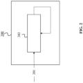
- FIG. 2 shows an equalizing device 200 according to an embodiment of the invention.
- the equalizing device 200 may comprise processing circuitry (not shown) configured to perform, conduct or initiate the various operations of the equalizing device 200 described herein.
- the processing circuitry may comprise hardware and software.
- the hardware may comprise analog circuitry or digital circuitry, or both analog and digital circuitry.
- the digital circuitry may comprise components such as application-specific integrated circuits (ASICs), field-programmable arrays (FPGAs), digital signal processors (DSPs), or multipurpose processors.
- the processing circuitry comprises one or more processors and a non-transitory memory connected to the one or more processors.
- the non-transitory memory may carry executable program code which, when executed by the one or more processors, causes the equalizing device 200 to perform, conduct or initiate the operations or methods described herein.
- the equalizing device 200 is particularly configured to process a digital signal 201.
- the digital signal 201 is derived, e.g. may be generated from, e.g. by an optical receiver 300, from an optical signal 301 received via a transmission channel 302 (see FIG. 3 ).
- the digital signal 201 represents samples of the optical signal 301. Each sample comprises two polarization components associated with two mutually orthogonal polarizations of the optical signal 301.
- the digital signal 201 comprises a training sequence 2011 followed by a payload 2012.
- the equalizing device 200 comprises a number of units or modules, including a 2x2 MIMO equalization filter 202.
- the equalizing device 200 is configured to generate a new instance of the 2x2 MIMO equalization filter 202 based on one or more preceding instances of the equalization filter 202 and on one or more samples of the payload 2012.
- the equalizing device 200 is further configured to equalize a sample of the payload 2012 by applying the new instance of the equalization filter 202 to the sample.
- the equalizing device 200 is configured to, by means of the MIMO equalization filter 202, compensate faster changes of the SOP of the optical signal 301 by equalizing the samples of the optical signal 301.
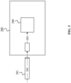
- FIG. 3 shows an optical receiver 300 according to an embodiment of the invention.
- the optical receiver 300 includes at least one device 200 as shown in FIG. 2 .
- the optical receiver 300 may particularly be a coherent optical receiver, i.e. may be a receiver configured to receive and process a coherent optical signal.
- the optical receiver 300 is configured to receive the optical signal 301 over the transmission channel 302, and to derive, e.g. generate, the digital signal 201 from the received optical signal 301.
- the optical receiver 300 may to this end comprise a coherent detector configured to derive an RF signal from the optical signal 301, and may further comprise an ADC configured to sample the RF signal.
- the digital signal 201 may in this case be a sampled version of the RF signal derived from the optical signal 301.
- the optical receiver 300 is configured to, by means of the equalizing device 200, compensate slower as well as faster changes of the SOP of the optical signal 301.
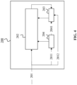
- the equalizing device 200 is configured to perform a blind gradient algorithm 203 (see FIG. 4 ) based on the one or more preceding instances of the equalization filter 202 and on the one or more samples of the payload 2012.
- a training-aided tap update block performs a tap-initialization of the MIMO equalization filter 202 at the beginning of each frame, based on the training sequence inserted between the payload data (channel estimation). That is, the equalizing device 200, according to the invention, is configured to perform a data-aided channel estimation 204 (see FIG. 4 ) based on the on the one or more samples of the training sequence 2011, to obtain one or more initial coefficients 2041.
- the Embodiments invention proposes a combined adaptation scheme.
- An equalizer architecture of the combination of the two adaptation schemes, according to the invention, is shown in FIG. 4 .
- same elements in all figures are labeled with the same reference signs and function likewise.
- the equalizing devices 200 as illustrated in FIG. 2 to FIG. 4 may include also DSP units or modules, which are, for instance, used for symbols detection and/or allowing processing fractional oversampled data.
- ⁇ 4 respectively, include units for carrying out at least one of serial/parallel conversion, an Overlap-Discard (OLD) method, Fast Fourier Transform (FFT) or inverse FFT (IFFT), Frame Alignment, Folding Decimation, signal buffering, carrier frequency offsetting, carrier phase compensation, symbol alignment or the like.
- OLD Overlap-Discard
- FFT Fast Fourier Transform
- IFFT inverse FFT
- Frame Alignment Frame Alignment
- Folding Decimation signal buffering
- carrier frequency offsetting carrier frequency offsetting
- carrier phase compensation symbol alignment or the like.
- the equalizing device 200 as shown in FIG. 4 is further configured to perform the blind gradient algorithm 203 based on the one or more preceding instances of the equalization filter 202, on the one or more samples of the payload 2012, and on the one or more obtained initial coefficients.
- the one or more initial coefficients are obtained from the data-aided channel estimation 204 based on the training sequence 2011.
- the combination of training-aided channel estimation and gradient-algorithm (i.e. LMS) adaptation to calculate the tap coefficients of the 2x2 MIMO equalizer is implemented, according to the invention.
- the combined scheme provides significantly higher SOP tracking speeds than the individual schemes.
- a signaling overhead and a degree of parallelization can also be reduced. This is because the invention allows updating the tap filter symbol by symbol, i.e. a updating the tap filter for every symbol, independent of the sample parallelization p.
- the digital signal 201 may comprise a sequence of data blocks, where each data block comprises a training sequence followed by a payload. Accordingly, the equalizing device 200 may be further configured to re-order the sequence of data blocks into p parallel samples per symbol, p being a positive integer, and each sample comprising one or more training sequences and a payload. In addition, the equalizing device 200 may be also configured to equalize each sample of the p parallel samples of the digital signal 201.
- a sample reordering block may be required to allow the blind algorithm to operate with a faster tap update rate (up to the symbol rate R, i.e. a symbol-by-symbol update), in order to be independent on the parallelization factor q.
- the faster update rate will allow for tracking of faster SOP changes.
- the equalizing device 200 may be configured to re-order the sequence of data blocks using a FIFO mechanism.
- the equalizing device 200 may be further configured to buffer the reordered p parallel samples before the equalization is performed.
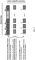
- FIG. 5 shows a sample flow through an equalizing device 200.
- the equalizing device 200 may be the equalizing devices 200 as illustrated in FIG. 2 to FIG. 4 .
- a data-aided channel estimation scheme based on training sequences is used to calculate the initial tap weights for the blind tap update for each payload block.
- each payload block can be independently processed with the blind gradient tap-adaptation stage, e.g. the DD-LMS.
- input signal shown in FIG. 5 may be the digital signal 201 as shown in FIG. 2 to FIG. 4 , which includes training sequences (TS as shown in FIG. 5 ) for channel estimation (CE).
- a pre-frame tap initialization of a 2 ⁇ 2 MIMO equalization filter 202 is preformed based on the CE.
- the 2 ⁇ 2 MIMO equalization filter 202 is the 2 ⁇ 2 MIMO equalization filter 202 as shown in FIG. 2 to FIG. 4 .
- a blind DD-LMS update adaptation is performed on output signal, e.g. from the 2 ⁇ 2 MIMO equalization filter 202.
- FIG. 6 shows an implementation of a sample-reordering block according to an embodiment of the invention.
- a 2 ⁇ 2 MIMO equalization filter 202 as shown in FIG. 6 can consist of p sub-equalizers.
- Each sub-equalizer processes only 1 Sa per clock cycle (1 Sa/cc), but uses a symbol-by-symbol blind DD-LMS update to maximize the tracking speed of the equalizer.
- FIG. 7 shows an architecture of the combination of the two adaptation schemes according to an embodiment of the invention.
- a training-aided tap update followed by a blind symbol-by-symbol tap update is performed by the equalizing device 200 as shown in FIG. 7 .
- the sample re-ordering block is required to improve the tolerance with respect to SOP rotations of the blind tap adaptation algorithm.
- the equalizing device 200 may be also configured to down-sample an input signal of p equalized samples per symbol to obtain an output signal of q samples per symbol, wherein q is a positive integer different from p. Particularly, this may be performed by a downsampling block included by the equalizing device 200, as shown in FIG. 7 .
- FIG. 8 shows a method 800 according to an embodiment of the invention.
- the method 800 is for processing a digital signal 201 representing samples of an optical signal 301 received via a channel 302. In particular, each sample comprising two polarization components associated with two mutually orthogonal polarizations of the optical signal 301.
- the digital signal 201 comprises a training sequence 2011 followed by a payload 2012.
- the method 800 may be carried out by the equalizing device 200 shown in FIG. 2 (or FIG. 3 , 4 or 7 ) or by the optical receiver 300 shown in FIG. 3 .
- the method 800 comprises a step 801 of generating a new instance of a 2x2 MIMO equalization filter 202 based on one or more preceding instances of the equalization filter 202 and on one or more samples of the payload data 2012.
- the method 800 also comprises a step 802 of equalizing a sample of the payload 2012 by applying the new instance of the 2x2 MIMO equalization filter 202 to the sample.
- the method further comprises performing a blind gradient algorithm based on the one or more preceding instances of the equalization filter 202 and on the one or more samples of the payload data 2012.
Landscapes
- Physics & Mathematics (AREA)
- Engineering & Computer Science (AREA)
- Computer Networks & Wireless Communication (AREA)
- Signal Processing (AREA)
- Electromagnetism (AREA)
- Spectroscopy & Molecular Physics (AREA)
- Cable Transmission Systems, Equalization Of Radio And Reduction Of Echo (AREA)
- Optical Communication System (AREA)
Description
- The present invention generally relates to processing a digital signal, particularly performing equalization on the digital signal. The digital signal is specifically derived from an optical signal transmitted over a channel, and thus the invention also relates to channel estimation. The invention is concerned especially with performing equalization on the digital signal in the presence of rapid State of Polarization (SOP) changes of the optical signal, and thus the invention also relates to SOP estimation. The invention can be applied in the field of Optical Ground Wire (OPGW) cables.
- The invention proposes an equalizing device, an optical receiver including the equalizing device, and an equalization method to be performed, for example, by the equalizing device or the optical receiver. The invention also proposes an optical signal including frames having a frame structure that enables the equalization of the rapid SOP changes.
- Amongst other technologies, OPGW cables have been used on overhead power transmission lines for lightning protection. This allows for a cheap deployment of optical fiber cables, which are placed in metal tubes in the center of the OPGW cables, and are shielded by one or more layers of armoring wires.
- However, in recent years, field and laboratory measurements indicated that a magnetic field, which is generated along the axis of the conductors by a lightning induced current, changes the SOP of the light in the optical fiber very rapidly. This becomes an issue, especially when using coherent optical polarization multiplexed transmission schemes. An initial assessment of the potential impact on the tracking abilities of coherent Digital Signal Processing (DSP) integrated circuits was made, and the SOP speed due to lightning strikes was estimated to be of the order of a few Mrad/s.
- Recent field trials confirmed this phenomenon, and measured SOP speeds up to 5.1Mrad/s. In recent laboratory experiments, fast SOP speeds even exceeding 8 Mrad/s were measured. Fast SOP changes are particularly an issue when using coherent optical polarization multiplexed transmission schemes of 100+Gb/s. Since most optical transceivers including commercial DSPs have been designed to withstand SOP changes mainly caused by mechanical vibrations, the SOP tracking capabilities are often only in the hundreds of Krad/s. Therefore, the industry arrived at a consensus that lightning strikes into OPGW cables can lead to traffic interruptions in metro and long-haul networks.
- The polarization tracking capability of the DSP depends on the MIMO equalizer adaptation (or update) speed as it determines how fast the equalizer can follow transient polarization changes. The adaptation scheme can be either implemented using blind or data-aided approaches. In case of blind adaptation, the update relies solely on signal statistics, in particular on the expected signal constellation. While the data-aided adaptation uses predefined training sequences for channel estimation (CE) that are inserted at the transmitter at the cost of signaling overhead. With regard to the adaptation speed, both approaches have their advantages and disadvantages. For instance, the blind scheme, exemplarily shown in
FIG. 1(a) , enables continuous adaptation without introducing signaling overhead. However, it requires a feedback loop which limits the update speed, in particular in case of a high degree of sample parallelization p which is typical for optical transceivers. As an example, p = 64. In this case, a tap update is possible only every 64th symbol which means that the equalizer cannot adapt fast enough to follow fast polarization changes. The data-aided scheme, exemplarily shown inFIG. 1(b) , can be implemented in a feed-forward structure and does not need a feedback loop. However, its adaptation speed depends on the repetition rate of the training sequence which is eventually limited by the required signaling overhead. - Most DSP application specific circuits (ASICs) available in the market use 2×2 MIMO equalizers based on gradient algorithms, such as the constant-modulus algorithm or the decision-directed least-mean-square (DD-LMS) algorithm. Considering also other processing algorithms, it seems possible to design 100G dual-polarization quadrature phase shift keying (DP-QPSK) DSP-ASICs able to track SOP rotation speeds up to a few hundred of Krad/s, covering most of the SOP transients occurring in buried fiber links and some cases of lightning. For higher-order Quadrature Amplitude Modulation (QAM), the SOP tracking capability of such DSPs is drastically reduced. While DSP based on 2×2 MIMO channel estimation improves the performance of the 2×2 MIMO equalizer, ultra-fast SOP rotation speeds due to currents induced by lightning on aerial fiber links cannot be tracked and compensated, unless unpractical training-overhead is used.
- Hence, an advanced equalizer for compensating very fast SOP Changes is desired.
-
US 9 374 170 B2 US 7 315 575 B2 discloses an equalization strategy for compensating channel distortions in a dual-polarization optical transport system wherein the received signal includes a complex signal of a first transmitted polarization component and a complex signal of a second transmitted polarization component. In a first step, a blind self recovery mode used a blind adaptation algorithm in calculating and modifying multiple complex equalizer transfer function coefficients to enables recovery of only the complex signal of the first transmitted polarization component. In a second step, equalization is performed in a training mode for recovery of the complex signals of the first and second transmitted polarization components. In a third step, equalization is performed in a data directed mode. The method is suited for a digital signal processing implementation in a coherent receiver. - In view of the above-mentioned issues, embodiments of the invention aim to improve the tracking and compensating of SOP changes. The objective is to provide an equalizing device and method, particularly based on 2×2 MIMO equalization, capable of tracking and compensating fast SOP changes (in the order of Mrad/s) of an optical signal. For instance, to track and compensate SOP changes caused by lightning strikes into OPGW cables. The invention also aims for digital signal processing on a digital signal derived from the optical signal to compensate the rapid SOP changes. Thereby, the invention aims for an efficient implementation of the equalization and combination with other conventional equalization.
- The objective is achieved by the embodiments provided in the enclosed independent claims. Advantageous implementations of the embodiments of the invention are further defined in the dependent claims.
- In particular, the embodiments of the invention propose combining two adaptation schemes of the 2×2 MIMO equalizer, in order to process a digital signal derived from an optical signal, and thereby to compensate fast SOP changes of the optical signal.
- A first aspect of the invention provides an equalizing device configured to process a digital signal representing samples of an optical signal received via a channel, each sample comprising two polarization components associated with two mutually orthogonal polarizations of the optical signal, wherein the digital signal comprises a training sequence followed by a payload, the equalizing device being configured to: generate a new instance of a 2×2 MIMO equalization filter based on one or more preceding instances of the equalization filter and on one or more samples of the payload, and equalize a sample of the payload by applying the new instance of the equalization filter to the sample.
- The channel may comprise an optical fiber, notably an optical fiber surrounded at least partly by an electrically conductive shield. For example, the digital signal may be a sampled version of a Radio-Frequency (RF) signal carried by the optical signal. The RF signal and thus the digital signal may carry a baseband signal, which contains the training sequences. The baseband signal may further carry payload data.
- The equalizing device is configured to perform a blind gradient algorithm based on the one or more preceding instances of the equalization filter and on the one or more samples of the payload.
- The blind scheme enables a continuous adaptation without introducing signaling overhead.
- The equalizing device is configured to perform a data-aided channel estimation based on the on the one or more samples of the training sequence, to obtain one or more initial coefficients.
- With the support of the data-aided scheme, by means of the training sequences, the device can efficiently remove effects of SOP rotations from the digital signal (slower and faster).
- Since the 2×2 MIMO channel estimation may obtained in every training sequence, the equalizer architectures allow accessing the channel also during the very fast SOP transients. All benefits of training-aided channel estimation are furthermore preserved. The equalization is modulation format transparent, i.e. the constellation plot of the payload data can be different than that of the training-sequences.
- The equalizing device is configured to perform the blind gradient algorithm based on the one or more preceding instances of the equalization filter, on the one or more samples of the payload, and on the one or more obtained initial coefficients.
- The invention proposes a combination of the two adaptation schemes. The combined scheme provides significantly high SOP tracking speeds than the individual schemes.
- In an implementation form of the first aspect, wherein the digital signal comprises a sequence of data blocks, each data block comprises a training sequence followed by a payload, and the equalizing device is further configured to: re-order the sequence of data blocks into p parallel samples per symbol, p being a positive integer, and each sample comprising at least one training sequence and a payload; and equalize each sample of the p parallel samples of the digital signal.
- In order to allow the blind algorithm to operate with a faster tap update rate (up to the symbol rate R, i.e. a symbol-by-symbol update), independent on the parallelization factor q. it is required to re-order the samples. The faster update rate will allow for tracking of faster SOP changes.
- In a further implementation form of the first aspect, the equalizing device is further configured to re-order the sequence of data blocks using a first in first out, FIFO, mechanism.
- By reordering the samples using FIFOs, each of the independent payload blocks will be serialized.
- In a further implementation form of the first aspect, the equalizing device is further configured to buffer the reordered p parallel samples before the equalization is performed.
- In an implementation form of the first aspect, the equalizing device is configured to compensate faster changes of a SOP of the optical signal by equalizing the samples of the optical signal.
- In an implementation form of the first aspect, the equalizing device is configured to perform a DD-LMS update equalization.
- After reordering the samples, a data-aided channel estimation scheme based on training sequences is used to calculate the initial tap weights for the blind tap update for each payload block. Afterwards, each payload block can be independently processed with the blind gradient tap-adaptation stage, e.g. the DD-LMS.
- In an implementation form of the first aspect, the equalizing device is configured to down-sample an input signal of p equalized samples per symbol to obtain an output signal of q samples per symbol, wherein q is a positive integer different from p.
- In particular, q refers to a parallelization factor after the down-sampling.
- In a further implementation form of the first aspect, the equalizing device is further configured to perform a blind gradient algorithm based on the one or more preceding instances of the equalization filter, the one or more samples of the payload, and the obtained output signal.
- Notably, the blind gradient algorithm is performed on the down-sampled signal.
- In an implementation form of the first aspect, the digital signal has a signal symbol rate R, wherein R is a positive integer.
- In a further implementation form of the first aspect, the equalizing device is configured to operate with a tap update rate up to R, in particular, wherein a tap update rate is R/2 or R/4.
- While a symbol-by-symbol tap update rate would allow the fastest tracking, the drawback is that large data buffering will lead to latency, if q frames need to be buffered. This can be avoided by choosing tap update rates of R/2, R/4, ..., for which then only q/2, q/4, ... frames need to be buffered.
- A second aspect of the invention provides an optical receiver, particularly coherent optical receiver, including an equalizing device according to the first aspect or any of its implementation forms, wherein the optical receiver is configured to receive the optical signal over the channel and to derive the digital signal from the optical signal.
- Optionally, the optical receiver is configured to derive the digital signal from the optical signal by deriving a RF signal from the optical signal and sampling the RF signal. For example, the optical receiver may comprise a coherent detector configured to derive the RF signal from the optical signal, and an Analog-to-Digital Converter (ADC) for sampling the RF signal. The digital signal will in this case be a sampled version of the RF signal derived from the optical signal.
- A third aspect of the invention provides a method for processing a digital signal representing samples of an optical signal received via a channel, each sample comprising two polarization components associated with two mutually orthogonal polarizations of the optical signal, wherein the digital signal comprises a training sequence followed by a payload, the method comprising: generating a new instance of a 2x2 Multiple Input Multiple Output, MIMO, equalization filter based on one or more preceding instances of the equalization filter and on one or more samples of the payload data, and equalizing a sample of the payload by applying the new instance of the 2x2 MIMO equalization filter to the sample.
- In the third aspect, the generating of the new instance of the equalization filter comprises performing a blind gradient algorithm based on the one or more preceding instances of the equalization filter and on the one or more samples of the payload data; performing a data-aided channel estimation based on the one or more samples of the training sequence, to obtain one or more initial coefficients; and performing the blind gradient algorithm based on the one or more preceding instances of the equalization filter, on the one or more samples of the payload, and on the one or more obtained initial coefficients.
- The method of the third aspect and its implementation forms achieve the advantages described above for the device of the first aspect and it respective implementation forms.
- It has to be noted that all devices, elements, units and means described in the present application could be implemented in the software or hardware elements or any kind of combination thereof. All steps which are performed by the various entities described in the present application as well as the functionalities described to be performed by the various entities are intended to mean that the respective entity is adapted to or configured to perform the respective steps and functionalities. Even if, in the following description of specific embodiments, a specific functionality or step to be performed by external entities is not reflected in the description of a specific detailed element of that entity which performs that specific step or functionality, it should be clear for a skilled person that these methods and functionalities can be implemented in respective software or hardware elements, or any kind of combination thereof. The invention is defined in the independent claims. Advantageous embodiments are set out in the dependent claims.
- The above described aspects and implementation forms of the present invention will be explained in the following description of specific embodiments in relation to the enclosed drawings, in which
- FIG. 1
- show examples of MIMO equalizer.
- FIG. 2
- shows an equalizing device according to an embodiment of the invention.
- FIG. 3
- shows an optical receiver according to an embodiment of the invention.
- FIG. 4
- shows an equalizing device according to an embodiment of the invention.
- FIG. 5
- shows a sample flow through a 2x2 MIMO equalization filter according to an embodiment of the invention.
- FIG. 6
- shows an implementation of a sample-reordering block according to an embodiment of the invention.
- FIG. 7
- shows an equalizing device according to an embodiment of the invention.
- FIG. 8
- shows a method according to an embodiment of the invention.
-
FIG. 2 shows an equalizingdevice 200 according to an embodiment of the invention. The equalizingdevice 200 may comprise processing circuitry (not shown) configured to perform, conduct or initiate the various operations of the equalizingdevice 200 described herein. The processing circuitry may comprise hardware and software. The hardware may comprise analog circuitry or digital circuitry, or both analog and digital circuitry. The digital circuitry may comprise components such as application-specific integrated circuits (ASICs), field-programmable arrays (FPGAs), digital signal processors (DSPs), or multipurpose processors. In one embodiment, the processing circuitry comprises one or more processors and a non-transitory memory connected to the one or more processors. The non-transitory memory may carry executable program code which, when executed by the one or more processors, causes the equalizingdevice 200 to perform, conduct or initiate the operations or methods described herein. - The equalizing
device 200 is particularly configured to process adigital signal 201. Thedigital signal 201 is derived, e.g. may be generated from, e.g. by anoptical receiver 300, from anoptical signal 301 received via a transmission channel 302 (seeFIG. 3 ). In particular, thedigital signal 201 represents samples of theoptical signal 301. Each sample comprises two polarization components associated with two mutually orthogonal polarizations of theoptical signal 301. Thedigital signal 201 comprises atraining sequence 2011 followed by apayload 2012. - The equalizing
device 200 comprises a number of units or modules, including a 2x2MIMO equalization filter 202. The equalizingdevice 200 is configured to generate a new instance of the 2x2MIMO equalization filter 202 based on one or more preceding instances of theequalization filter 202 and on one or more samples of thepayload 2012. The equalizingdevice 200 is further configured to equalize a sample of thepayload 2012 by applying the new instance of theequalization filter 202 to the sample. - The equalizing
device 200 is configured to, by means of theMIMO equalization filter 202, compensate faster changes of the SOP of theoptical signal 301 by equalizing the samples of theoptical signal 301. -
FIG. 3 shows anoptical receiver 300 according to an embodiment of the invention. Theoptical receiver 300 includes at least onedevice 200 as shown inFIG. 2 . Theoptical receiver 300 may particularly be a coherent optical receiver, i.e. may be a receiver configured to receive and process a coherent optical signal. - The
optical receiver 300 is configured to receive theoptical signal 301 over thetransmission channel 302, and to derive, e.g. generate, thedigital signal 201 from the receivedoptical signal 301. For instance, theoptical receiver 300 may to this end comprise a coherent detector configured to derive an RF signal from theoptical signal 301, and may further comprise an ADC configured to sample the RF signal. Thedigital signal 201 may in this case be a sampled version of the RF signal derived from theoptical signal 301. - The
optical receiver 300 is configured to, by means of the equalizingdevice 200, compensate slower as well as faster changes of the SOP of theoptical signal 301. - Because of the nature of the channel estimation approach, time-varying channel variations between two training sequences cannot be estimated. Therefore, it is desired to perform tracking of time-varying effects in the payload data by the support of a blind gradient algorithm such as DD-LMS which conventionally supports a tap update rate of R/q, where R referring to the signal symbol rate, q referring to the parallelization factor after the down-sampling). As aforementioned, in a typical ASIC implementation, q is in the order of 64, so that the update rate is R/64.
- Therefore, the equalizing
device 200, as shown inFIG. 1 andFIG. 2 , according to the invention, is configured to perform a blind gradient algorithm 203 (seeFIG. 4 ) based on the one or more preceding instances of theequalization filter 202 and on the one or more samples of thepayload 2012. - A training-aided tap update block performs a tap-initialization of the
MIMO equalization filter 202 at the beginning of each frame, based on the training sequence inserted between the payload data (channel estimation). That is, the equalizingdevice 200, according to the invention, is configured to perform a data-aided channel estimation 204 (seeFIG. 4 ) based on the on the one or more samples of thetraining sequence 2011, to obtain one or more initial coefficients 2041. - The Embodiments invention proposes a combined adaptation scheme. An equalizer architecture of the combination of the two adaptation schemes, according to the invention, is shown in
FIG. 4 . Notably, same elements in all figures are labeled with the same reference signs and function likewise. The equalizingdevices 200 as illustrated inFIG. 2 to FIG. 4 , respectively, may include also DSP units or modules, which are, for instance, used for symbols detection and/or allowing processing fractional oversampled data. In particular, DSP units of the equalizingdevices 200 shown inFIG. 2 to FIG. 4 , respectively, include units for carrying out at least one of serial/parallel conversion, an Overlap-Discard (OLD) method, Fast Fourier Transform (FFT) or inverse FFT (IFFT), Frame Alignment, Folding Decimation, signal buffering, carrier frequency offsetting, carrier phase compensation, symbol alignment or the like. - According to the invention, the equalizing
device 200 as shown inFIG. 4 , is further configured to perform theblind gradient algorithm 203 based on the one or more preceding instances of theequalization filter 202, on the one or more samples of thepayload 2012, and on the one or more obtained initial coefficients. Notably, the one or more initial coefficients are obtained from the data-aidedchannel estimation 204 based on thetraining sequence 2011. - In this way, the combination of training-aided channel estimation and gradient-algorithm (i.e. LMS) adaptation to calculate the tap coefficients of the 2x2 MIMO equalizer is implemented, according to the invention. The combined scheme provides significantly higher SOP tracking speeds than the individual schemes. A signaling overhead and a degree of parallelization can also be reduced. This is because the invention allows updating the tap filter symbol by symbol, i.e. a updating the tap filter for every symbol, independent of the sample parallelization p.
- The
digital signal 201, according to an embodiment of the invention, may comprise a sequence of data blocks, where each data block comprises a training sequence followed by a payload. Accordingly, the equalizingdevice 200 may be further configured to re-order the sequence of data blocks into p parallel samples per symbol, p being a positive integer, and each sample comprising one or more training sequences and a payload. In addition, the equalizingdevice 200 may be also configured to equalize each sample of the p parallel samples of thedigital signal 201. - According to an embodiment of the invention, a sample reordering block may be required to allow the blind algorithm to operate with a faster tap update rate (up to the symbol rate R, i.e. a symbol-by-symbol update), in order to be independent on the parallelization factor q. The faster update rate will allow for tracking of faster SOP changes. Moreover, the equalizing
device 200 may be configured to re-order the sequence of data blocks using a FIFO mechanism. - According to an embodiment of the invention, the equalizing
device 200 may be further configured to buffer the reordered p parallel samples before the equalization is performed. - While a symbol-by-symbol tap update rate would allow the fastest tracking, the drawback is that q frames need to be buffered in the sample reordering block, and large data buffering leads to latency. This can be avoided by choosing tap update rates of R/2, R/4, ... , for which then only q/2, q/4, ... frames need to be buffered. In this way, the equalizer architecture can be designed to provide an optimized trade-off between tracking speed and latency.
-
FIG. 5 shows a sample flow through an equalizingdevice 200. In particular, the equalizingdevice 200 may be the equalizingdevices 200 as illustrated inFIG. 2 to FIG. 4 . According to an embodiment of the invention, after the sequences of data blocks are reordered (e.g. by a sample reordering block), a data-aided channel estimation scheme based on training sequences is used to calculate the initial tap weights for the blind tap update for each payload block. Afterwards, each payload block can be independently processed with the blind gradient tap-adaptation stage, e.g. the DD-LMS. - In particular, input signal shown in
FIG. 5 may be thedigital signal 201 as shown inFIG. 2 to FIG. 4 , which includes training sequences (TS as shown inFIG. 5 ) for channel estimation (CE). A pre-frame tap initialization of a 2×2MIMO equalization filter 202 is preformed based on the CE. In particular, the 2×2MIMO equalization filter 202 is the 2×2MIMO equalization filter 202 as shown inFIG. 2 to FIG. 4 . Further, a blind DD-LMS update adaptation is performed on output signal, e.g. from the 2×2MIMO equalization filter 202. -
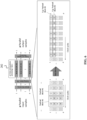
FIG. 6 shows an implementation of a sample-reordering block according to an embodiment of the invention. By reordering the samples using FIFOs, each of the independent payload blocks will be serialized. For instance, a 2×2MIMO equalization filter 202 as shown inFIG. 6 can consist of p sub-equalizers. Each sub-equalizer processes only 1 Sa per clock cycle (1 Sa/cc), but uses a symbol-by-symbol blind DD-LMS update to maximize the tracking speed of the equalizer. -
FIG. 7 shows an architecture of the combination of the two adaptation schemes according to an embodiment of the invention. In particular, a training-aided tap update followed by a blind symbol-by-symbol tap update is performed by the equalizingdevice 200 as shown inFIG. 7 . The sample re-ordering block is required to improve the tolerance with respect to SOP rotations of the blind tap adaptation algorithm. Further, the equalizingdevice 200 may be also configured to down-sample an input signal of p equalized samples per symbol to obtain an output signal of q samples per symbol, wherein q is a positive integer different from p. Particularly, this may be performed by a downsampling block included by the equalizingdevice 200, as shown inFIG. 7 . -
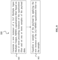
FIG. 8 shows amethod 800 according to an embodiment of the invention. Themethod 800 is for processing adigital signal 201 representing samples of anoptical signal 301 received via achannel 302. In particular, each sample comprising two polarization components associated with two mutually orthogonal polarizations of theoptical signal 301. Thedigital signal 201 comprises atraining sequence 2011 followed by apayload 2012. Themethod 800 may be carried out by the equalizingdevice 200 shown inFIG. 2 (orFIG. 3 ,4 or7 ) or by theoptical receiver 300 shown inFIG. 3 . - The
method 800 comprises astep 801 of generating a new instance of a 2x2MIMO equalization filter 202 based on one or more preceding instances of theequalization filter 202 and on one or more samples of thepayload data 2012. Themethod 800 also comprises astep 802 of equalizing a sample of thepayload 2012 by applying the new instance of the 2x2MIMO equalization filter 202 to the sample. - In the
step 801 of generating the new instance of theequalization filter 202, the method further comprises performing a blind gradient algorithm based on the one or more preceding instances of theequalization filter 202 and on the one or more samples of thepayload data 2012. - The present invention has been described in conjunction with various embodiments as examples as well as implementations. However, other variations can be understood and effected by those persons skilled in the art and practicing the claimed invention, from the studies of the drawings, this disclosure and the independent claims. In the claims as well as in the description the word "comprising" does not exclude other elements or steps and the indefinite article "a" or "an" does not exclude a plurality. A single element or other unit may fulfill the functions of several entities or items recited in the claims. The mere fact that certain measures are recited in the mutual different dependent claims does not indicate that a combination of these measures cannot be used in an advantageous implementation within the scope of the invention as defined by the appended claims.
Claims (12)
- An equalizing device (200) for processing a digital signal (201) representing samples of an optical signal (301) received via a channel (302), each sample comprising two polarization components associated with two mutually orthogonal polarizations of the optical signal (301), wherein the digital signal (201) comprises a training sequence (2011) followed by a payload (2012), the equalizing device (200) being configured to:generate a new instance of a 2x2 Multiple Input Multiple Output, MIMO, equalization filter (202) based on one or more preceding instances of the equalization filter (202) and on one or more samples of the payload (2012), andequalize a sample of the payload (2012) by applying the new instance of the equalization filter (202) to the sample;wherein to generate a new instance of the equalization filter (202) the equalizing device (200) is further configured toperform a data-aided channel estimation (204) based on the one or more samples of the training sequence (2011), to obtain one or more initial coefficients (2041); andperform a blind gradient algorithm (203) based on the one or more preceding instances of the equalization filter (202), on the one or more samples of the payload (2012), and on the one or more obtained initial coefficients (2041).
- The equalizing device (200) according to claim 1, wherein the digital signal (201) comprises a sequence of data blocks, each data block comprises a training sequence followed by a payload, and the equalizing device (200) is further configured to:re-order the sequence of data blocks into p parallel samples per symbol, p being a positive integer, and each sample comprising at least one training sequence and a payload; andequalize each sample of the p parallel samples of the digital signal (201).
- The equalizing device (200) according to claim 2, configured to:
re-order the sequence of data blocks using a first in first out, FIFO, mechanism. - The equalizing device (200) according to claim 2 or 3, configured to:
buffer the reordered p parallel samples before the equalization is performed. - The equalizing device (200) according to any one of claims 1 to 4, configured to:
compensate faster changes of a State of Polarization, SOP, of the optical signal (301) by equalizing the samples of the optical signal (301). - The equalizing device (200) according to any one of claims 1 to 5, configured to:
perform a blind decision-directed least-mean-square, DD-LMS, update equalization. - The equalizing device (200) according to any one of claims 1 to 6, configured to:
down-sample an input signal of p equalized samples per symbol to obtain an output signal of q samples per symbol, wherein q is a positive integer different from p. - The equalizing device (200) according to claim 7, configured to
perform a blind gradient algorithm based on the one or more preceding instances of the equalization filter (202), the one or more samples of the payload, and the obtained output signal. - The equalizing device (200) according to any one of claims 1 to 8, wherein
the digital signal (201) has a signal symbol rate R, wherein R is a positive integer. - The equalizing device (200) according to claim 9, configured to:
operate with a tap update rate up to R, in particular, wherein a tap update rate is R/2 or R/4. - An optical receiver (300), particularly a coherent optical receiver, including an equalizing device (200) according to any one of the claims 1 to 10, wherein
the optical receiver (300) is configured to receive the optical signal (301) over the channel (302) and to derive the digital signal (201) from the optical signal (301). - A method (800) for processing a digital signal (201) representing samples of an optical signal (301) received via a channel (302), each sample comprising two polarization components associated with two mutually orthogonal polarizations of the optical signal, wherein the digital signal (201) comprises a training sequence (2011) followed by a payload (2012), the method (800) comprising:generating (801) a new instance of a 2x2 Multiple Input Multiple Output, MIMO, equalization filter (202) based on one or more preceding instances of the equalization filter (202) and on one or more samples of the payload data (2012), andequalizing (802) a sample of the payload (2012) by applying the new instance of the 2x2 MIMO equalization filter (202) to the sample,wherein the step of generating a new instance of the equalization filter (302) further comprises:performing a data-aided channel estimation (204) based on the one or more samples of the training sequence (2011), to obtain one or more initial coefficients (2041), andperforming a blind gradient algorithm (203) based on the one or more preceding instances of the equalization filter (202), on the one or more samples of the payload (2012), and on the one or more obtained initial coefficients (2041).
Applications Claiming Priority (1)
| Application Number | Priority Date | Filing Date | Title |
|---|---|---|---|
| PCT/EP2019/075042 WO2021052579A1 (en) | 2019-09-18 | 2019-09-18 | Equalizing device for compensating rapid state of polarization changes of an optical signal |
Publications (2)
| Publication Number | Publication Date |
|---|---|
| EP3900225A1 EP3900225A1 (en) | 2021-10-27 |
| EP3900225B1 true EP3900225B1 (en) | 2024-11-27 |
Family
ID=67999642
Family Applications (1)
| Application Number | Title | Priority Date | Filing Date |
|---|---|---|---|
| EP19773039.3A Active EP3900225B1 (en) | 2019-09-18 | 2019-09-18 | Equalizing device for compensating rapid state of polarization changes of an optical signal |
Country Status (2)
| Country | Link |
|---|---|
| EP (1) | EP3900225B1 (en) |
| WO (1) | WO2021052579A1 (en) |
Families Citing this family (1)
| Publication number | Priority date | Publication date | Assignee | Title |
|---|---|---|---|---|
| WO2025214586A1 (en) * | 2024-04-09 | 2025-10-16 | Huawei Technologies Co., Ltd. | A mimo receiver and a method for performing a mimo channel equalization |
Family Cites Families (4)
| Publication number | Priority date | Publication date | Assignee | Title |
|---|---|---|---|---|
| US7315575B2 (en) * | 2004-03-08 | 2008-01-01 | Nortel Networks Limited | Equalization strategy for dual-polarization optical transport system |
| JP2015122632A (en) * | 2013-12-24 | 2015-07-02 | 富士通株式会社 | Optical communication receiver |
| EP3195506B1 (en) * | 2014-09-19 | 2019-01-23 | Telefonaktiebolaget LM Ericsson (publ) | Optical transmitters and receivers using polarization multiplexing |
| CN106161329B (en) * | 2015-04-24 | 2019-07-30 | 富士通株式会社 | Signal processing device, signal transmitting device and receiver |
-
2019
- 2019-09-18 WO PCT/EP2019/075042 patent/WO2021052579A1/en not_active Ceased
- 2019-09-18 EP EP19773039.3A patent/EP3900225B1/en active Active
Also Published As
| Publication number | Publication date |
|---|---|
| WO2021052579A1 (en) | 2021-03-25 |
| EP3900225A1 (en) | 2021-10-27 |
Similar Documents
| Publication | Publication Date | Title |
|---|---|---|
| JP6206545B1 (en) | Transmission characteristic compensation apparatus, transmission characteristic compensation method, and communication apparatus | |
| EP2613452B1 (en) | Digital filter device, digital filtering method, and control program for digital filter device | |
| Randel et al. | Complexity analysis of adaptive frequency-domain equalization for MIMO-SDM transmission | |
| US20230361882A1 (en) | Frequency deviation compensation scheme and frequency deviation compensation method | |
| CN105191242B (en) | Implement the method and communication device of non-integer subsymbol adaptive equalization | |
| EP2399353B1 (en) | Equaliser for an optical transmission system | |
| EP3465949B1 (en) | Apparatus and method for processing a digital signal in a frequency domain linear equalizer | |
| US9608735B2 (en) | MIMO equalization optimized for baud rate clock recovery in coherent DP-QPSK metro systems | |
| GB2404542A (en) | Multicarrier modulated signal receiver which cancels impulse noise using an estimate derived from the equalised signal | |
| US9917712B2 (en) | Frequency domain equalizer for optical communications | |
| US20150093119A1 (en) | Symbol spaced adaptive mimo equalization for ultra high bit rate optical communication systems | |
| JPWO2018198891A1 (en) | Signal combining device and signal combining method | |
| US20240007193A1 (en) | Communication system, receiver, distortion detection device, and method | |
| WO2013185845A1 (en) | Method for adapting an equalizer to equalize a composite characteristic of an optical communication channel | |
| US20210203416A1 (en) | Equalizing device for compensating rapid state of polarization changes of an optical signal | |
| US8989324B2 (en) | Receiver and receiving method | |
| EP3900225A1 (en) | Equalizing device for compensating rapid state of polarization changes of an optical signal | |
| WO2015052894A1 (en) | Carrier frequency deviation estimation device and carrier frequency deviation estimation method | |
| WO2022174363A1 (en) | Mimo equalization with weighted coefficients update | |
| JP2024117854A (en) | COMMUNICATION SYSTEM, RECEIVER, EQUALIZATION SIGNAL PROCESSING CIRCUIT, EQUALIZATION SIGNAL PROCESSING METHOD, AND PROGRAM |
Legal Events
| Date | Code | Title | Description |
|---|---|---|---|
| STAA | Information on the status of an ep patent application or granted ep patent |
Free format text: STATUS: UNKNOWN |
|
| STAA | Information on the status of an ep patent application or granted ep patent |
Free format text: STATUS: THE INTERNATIONAL PUBLICATION HAS BEEN MADE |
|
| PUAI | Public reference made under article 153(3) epc to a published international application that has entered the european phase |
Free format text: ORIGINAL CODE: 0009012 |
|
| STAA | Information on the status of an ep patent application or granted ep patent |
Free format text: STATUS: REQUEST FOR EXAMINATION WAS MADE |
|
| 17P | Request for examination filed |
Effective date: 20210721 |
|
| AK | Designated contracting states |
Kind code of ref document: A1 Designated state(s): AL AT BE BG CH CY CZ DE DK EE ES FI FR GB GR HR HU IE IS IT LI LT LU LV MC MK MT NL NO PL PT RO RS SE SI SK SM TR |
|
| RAP3 | Party data changed (applicant data changed or rights of an application transferred) |
Owner name: FRAUNHOFER-GESELLSCHAFT ZUR FOERDERUNG DER ANGEWANDTEN FORSCHUNG E.V. Owner name: HUAWEI TECHNOLOGIES CO., LTD. |
|
| DAV | Request for validation of the european patent (deleted) | ||
| DAX | Request for extension of the european patent (deleted) | ||
| GRAP | Despatch of communication of intention to grant a patent |
Free format text: ORIGINAL CODE: EPIDOSNIGR1 |
|
| STAA | Information on the status of an ep patent application or granted ep patent |
Free format text: STATUS: GRANT OF PATENT IS INTENDED |
|
| INTG | Intention to grant announced |
Effective date: 20240715 |
|
| GRAS | Grant fee paid |
Free format text: ORIGINAL CODE: EPIDOSNIGR3 |
|
| GRAA | (expected) grant |
Free format text: ORIGINAL CODE: 0009210 |
|
| STAA | Information on the status of an ep patent application or granted ep patent |
Free format text: STATUS: THE PATENT HAS BEEN GRANTED |
|
| AK | Designated contracting states |
Kind code of ref document: B1 Designated state(s): AL AT BE BG CH CY CZ DE DK EE ES FI FR GB GR HR HU IE IS IT LI LT LU LV MC MK MT NL NO PL PT RO RS SE SI SK SM TR |
|
| REG | Reference to a national code |
Ref country code: GB Ref legal event code: FG4D |
|
| REG | Reference to a national code |
Ref country code: CH Ref legal event code: EP |
|
| REG | Reference to a national code |
Ref country code: DE Ref legal event code: R096 Ref document number: 602019062612 Country of ref document: DE |
|
| REG | Reference to a national code |
Ref country code: IE Ref legal event code: FG4D |
|
| REG | Reference to a national code |
Ref country code: LT Ref legal event code: MG9D |
|
| REG | Reference to a national code |
Ref country code: NL Ref legal event code: MP Effective date: 20241127 |
|
| PG25 | Lapsed in a contracting state [announced via postgrant information from national office to epo] |
Ref country code: PT Free format text: LAPSE BECAUSE OF FAILURE TO SUBMIT A TRANSLATION OF THE DESCRIPTION OR TO PAY THE FEE WITHIN THE PRESCRIBED TIME-LIMIT Effective date: 20250327 Ref country code: IS Free format text: LAPSE BECAUSE OF FAILURE TO SUBMIT A TRANSLATION OF THE DESCRIPTION OR TO PAY THE FEE WITHIN THE PRESCRIBED TIME-LIMIT Effective date: 20250327 Ref country code: HR Free format text: LAPSE BECAUSE OF FAILURE TO SUBMIT A TRANSLATION OF THE DESCRIPTION OR TO PAY THE FEE WITHIN THE PRESCRIBED TIME-LIMIT Effective date: 20241127 |
|
| PG25 | Lapsed in a contracting state [announced via postgrant information from national office to epo] |
Ref country code: FI Free format text: LAPSE BECAUSE OF FAILURE TO SUBMIT A TRANSLATION OF THE DESCRIPTION OR TO PAY THE FEE WITHIN THE PRESCRIBED TIME-LIMIT Effective date: 20241127 Ref country code: NL Free format text: LAPSE BECAUSE OF FAILURE TO SUBMIT A TRANSLATION OF THE DESCRIPTION OR TO PAY THE FEE WITHIN THE PRESCRIBED TIME-LIMIT Effective date: 20241127 |
|
| REG | Reference to a national code |
Ref country code: AT Ref legal event code: MK05 Ref document number: 1746729 Country of ref document: AT Kind code of ref document: T Effective date: 20241127 |
|
| PG25 | Lapsed in a contracting state [announced via postgrant information from national office to epo] |
Ref country code: BG Free format text: LAPSE BECAUSE OF FAILURE TO SUBMIT A TRANSLATION OF THE DESCRIPTION OR TO PAY THE FEE WITHIN THE PRESCRIBED TIME-LIMIT Effective date: 20241127 |
|
| PG25 | Lapsed in a contracting state [announced via postgrant information from national office to epo] |
Ref country code: ES Free format text: LAPSE BECAUSE OF FAILURE TO SUBMIT A TRANSLATION OF THE DESCRIPTION OR TO PAY THE FEE WITHIN THE PRESCRIBED TIME-LIMIT Effective date: 20241127 |
|
| PG25 | Lapsed in a contracting state [announced via postgrant information from national office to epo] |
Ref country code: NO Free format text: LAPSE BECAUSE OF FAILURE TO SUBMIT A TRANSLATION OF THE DESCRIPTION OR TO PAY THE FEE WITHIN THE PRESCRIBED TIME-LIMIT Effective date: 20250227 |
|
| PG25 | Lapsed in a contracting state [announced via postgrant information from national office to epo] |
Ref country code: LV Free format text: LAPSE BECAUSE OF FAILURE TO SUBMIT A TRANSLATION OF THE DESCRIPTION OR TO PAY THE FEE WITHIN THE PRESCRIBED TIME-LIMIT Effective date: 20241127 Ref country code: GR Free format text: LAPSE BECAUSE OF FAILURE TO SUBMIT A TRANSLATION OF THE DESCRIPTION OR TO PAY THE FEE WITHIN THE PRESCRIBED TIME-LIMIT Effective date: 20250228 Ref country code: AT Free format text: LAPSE BECAUSE OF FAILURE TO SUBMIT A TRANSLATION OF THE DESCRIPTION OR TO PAY THE FEE WITHIN THE PRESCRIBED TIME-LIMIT Effective date: 20241127 |
|
| PG25 | Lapsed in a contracting state [announced via postgrant information from national office to epo] |
Ref country code: PL Free format text: LAPSE BECAUSE OF FAILURE TO SUBMIT A TRANSLATION OF THE DESCRIPTION OR TO PAY THE FEE WITHIN THE PRESCRIBED TIME-LIMIT Effective date: 20241127 |
|
| PG25 | Lapsed in a contracting state [announced via postgrant information from national office to epo] |
Ref country code: RS Free format text: LAPSE BECAUSE OF FAILURE TO SUBMIT A TRANSLATION OF THE DESCRIPTION OR TO PAY THE FEE WITHIN THE PRESCRIBED TIME-LIMIT Effective date: 20250227 |
|
| PG25 | Lapsed in a contracting state [announced via postgrant information from national office to epo] |
Ref country code: SM Free format text: LAPSE BECAUSE OF FAILURE TO SUBMIT A TRANSLATION OF THE DESCRIPTION OR TO PAY THE FEE WITHIN THE PRESCRIBED TIME-LIMIT Effective date: 20241127 |
|
| PG25 | Lapsed in a contracting state [announced via postgrant information from national office to epo] |
Ref country code: DK Free format text: LAPSE BECAUSE OF FAILURE TO SUBMIT A TRANSLATION OF THE DESCRIPTION OR TO PAY THE FEE WITHIN THE PRESCRIBED TIME-LIMIT Effective date: 20241127 |
|
| PG25 | Lapsed in a contracting state [announced via postgrant information from national office to epo] |
Ref country code: EE Free format text: LAPSE BECAUSE OF FAILURE TO SUBMIT A TRANSLATION OF THE DESCRIPTION OR TO PAY THE FEE WITHIN THE PRESCRIBED TIME-LIMIT Effective date: 20241127 |
|
| PG25 | Lapsed in a contracting state [announced via postgrant information from national office to epo] |
Ref country code: RO Free format text: LAPSE BECAUSE OF FAILURE TO SUBMIT A TRANSLATION OF THE DESCRIPTION OR TO PAY THE FEE WITHIN THE PRESCRIBED TIME-LIMIT Effective date: 20241127 |
|
| PG25 | Lapsed in a contracting state [announced via postgrant information from national office to epo] |
Ref country code: SK Free format text: LAPSE BECAUSE OF FAILURE TO SUBMIT A TRANSLATION OF THE DESCRIPTION OR TO PAY THE FEE WITHIN THE PRESCRIBED TIME-LIMIT Effective date: 20241127 |
|
| PG25 | Lapsed in a contracting state [announced via postgrant information from national office to epo] |
Ref country code: CZ Free format text: LAPSE BECAUSE OF FAILURE TO SUBMIT A TRANSLATION OF THE DESCRIPTION OR TO PAY THE FEE WITHIN THE PRESCRIBED TIME-LIMIT Effective date: 20241127 |
|
| PG25 | Lapsed in a contracting state [announced via postgrant information from national office to epo] |
Ref country code: IT Free format text: LAPSE BECAUSE OF FAILURE TO SUBMIT A TRANSLATION OF THE DESCRIPTION OR TO PAY THE FEE WITHIN THE PRESCRIBED TIME-LIMIT Effective date: 20241127 |
|
| REG | Reference to a national code |
Ref country code: DE Ref legal event code: R097 Ref document number: 602019062612 Country of ref document: DE |
|
| PG25 | Lapsed in a contracting state [announced via postgrant information from national office to epo] |
Ref country code: SE Free format text: LAPSE BECAUSE OF FAILURE TO SUBMIT A TRANSLATION OF THE DESCRIPTION OR TO PAY THE FEE WITHIN THE PRESCRIBED TIME-LIMIT Effective date: 20241127 |
|
| PLBE | No opposition filed within time limit |
Free format text: ORIGINAL CODE: 0009261 |
|
| STAA | Information on the status of an ep patent application or granted ep patent |
Free format text: STATUS: NO OPPOSITION FILED WITHIN TIME LIMIT |
|
| REG | Reference to a national code |
Ref country code: CH Ref legal event code: L10 Free format text: ST27 STATUS EVENT CODE: U-0-0-L10-L00 (AS PROVIDED BY THE NATIONAL OFFICE) Effective date: 20251008 |
|
| PGFP | Annual fee paid to national office [announced via postgrant information from national office to epo] |
Ref country code: DE Payment date: 20250730 Year of fee payment: 7 |
|
| PGFP | Annual fee paid to national office [announced via postgrant information from national office to epo] |
Ref country code: GB Payment date: 20250731 Year of fee payment: 7 |
|
| PGFP | Annual fee paid to national office [announced via postgrant information from national office to epo] |
Ref country code: FR Payment date: 20250808 Year of fee payment: 7 |
|
| 26N | No opposition filed |
Effective date: 20250828 |
|
| REG | Reference to a national code |
Ref country code: CH Ref legal event code: H13 Free format text: ST27 STATUS EVENT CODE: U-0-0-H10-H13 (AS PROVIDED BY THE NATIONAL OFFICE) Effective date: 20260504 |
|
| PG25 | Lapsed in a contracting state [announced via postgrant information from national office to epo] |
Ref country code: LU Free format text: LAPSE BECAUSE OF NON-PAYMENT OF DUE FEES Effective date: 20250918 |
|
| REG | Reference to a national code |
Ref country code: BE Ref legal event code: MM Effective date: 20250930 |
|
| PG25 | Lapsed in a contracting state [announced via postgrant information from national office to epo] |
Ref country code: LT Free format text: LAPSE BECAUSE OF FAILURE TO SUBMIT A TRANSLATION OF THE DESCRIPTION OR TO PAY THE FEE WITHIN THE PRESCRIBED TIME-LIMIT Effective date: 20241127 |
|
| PG25 | Lapsed in a contracting state [announced via postgrant information from national office to epo] |
Ref country code: MC Free format text: LAPSE BECAUSE OF FAILURE TO SUBMIT A TRANSLATION OF THE DESCRIPTION OR TO PAY THE FEE WITHIN THE PRESCRIBED TIME-LIMIT Effective date: 20241127 |
|
| PG25 | Lapsed in a contracting state [announced via postgrant information from national office to epo] |
Ref country code: BE Free format text: LAPSE BECAUSE OF NON-PAYMENT OF DUE FEES Effective date: 20250930 Ref country code: IE Free format text: LAPSE BECAUSE OF NON-PAYMENT OF DUE FEES Effective date: 20250918 Ref country code: CH Free format text: LAPSE BECAUSE OF NON-PAYMENT OF DUE FEES Effective date: 20250930 |