EP3899997B1 - An electrical switch and an electrical switch system - Google Patents
An electrical switch and an electrical switch system Download PDFInfo
- Publication number
- EP3899997B1 EP3899997B1 EP19831864.4A EP19831864A EP3899997B1 EP 3899997 B1 EP3899997 B1 EP 3899997B1 EP 19831864 A EP19831864 A EP 19831864A EP 3899997 B1 EP3899997 B1 EP 3899997B1
- Authority
- EP
- European Patent Office
- Prior art keywords
- wheel
- electrical switch
- switch
- contact
- arm
- Prior art date
- Legal status (The legal status is an assumption and is not a legal conclusion. Google has not performed a legal analysis and makes no representation as to the accuracy of the status listed.)
- Active
Links
Images




Classifications
-
- H—ELECTRICITY
- H01—ELECTRIC ELEMENTS
- H01H—ELECTRIC SWITCHES; RELAYS; SELECTORS; EMERGENCY PROTECTIVE DEVICES
- H01H1/00—Contacts
- H01H1/12—Contacts characterised by the manner in which co-operating contacts engage
- H01H1/14—Contacts characterised by the manner in which co-operating contacts engage by abutting
- H01H1/16—Contacts characterised by the manner in which co-operating contacts engage by abutting by rolling; by wrapping; Roller or ball contacts
-
- H—ELECTRICITY
- H01—ELECTRIC ELEMENTS
- H01H—ELECTRIC SWITCHES; RELAYS; SELECTORS; EMERGENCY PROTECTIVE DEVICES
- H01H1/00—Contacts
- H01H1/12—Contacts characterised by the manner in which co-operating contacts engage
- H01H1/36—Contacts characterised by the manner in which co-operating contacts engage by sliding
- H01H1/42—Knife-and-clip contacts
-
- H—ELECTRICITY
- H01—ELECTRIC ELEMENTS
- H01H—ELECTRIC SWITCHES; RELAYS; SELECTORS; EMERGENCY PROTECTIVE DEVICES
- H01H33/00—High-tension or heavy-current switches with arc-extinguishing or arc-preventing means
- H01H33/02—Details
- H01H33/04—Means for extinguishing or preventing arc between current-carrying parts
- H01H33/20—Means for extinguishing or preventing arc between current-carrying parts using arcing horns
-
- H—ELECTRICITY
- H01—ELECTRIC ELEMENTS
- H01H—ELECTRIC SWITCHES; RELAYS; SELECTORS; EMERGENCY PROTECTIVE DEVICES
- H01H33/00—High-tension or heavy-current switches with arc-extinguishing or arc-preventing means
- H01H33/02—Details
- H01H33/28—Power arrangements internal to the switch for operating the driving mechanism
- H01H33/285—Power arrangements internal to the switch for operating the driving mechanism using electro-dynamic repulsion
-
- H—ELECTRICITY
- H01—ELECTRIC ELEMENTS
- H01H—ELECTRIC SWITCHES; RELAYS; SELECTORS; EMERGENCY PROTECTIVE DEVICES
- H01H9/00—Details of switching devices, not covered by groups H01H1/00 - H01H7/00
- H01H9/30—Means for extinguishing or preventing arc between current-carrying parts
- H01H9/38—Auxiliary contacts on to which the arc is transferred from the main contacts
-
- H—ELECTRICITY
- H01—ELECTRIC ELEMENTS
- H01H—ELECTRIC SWITCHES; RELAYS; SELECTORS; EMERGENCY PROTECTIVE DEVICES
- H01H9/00—Details of switching devices, not covered by groups H01H1/00 - H01H7/00
- H01H9/30—Means for extinguishing or preventing arc between current-carrying parts
- H01H9/46—Means for extinguishing or preventing arc between current-carrying parts using arcing horns
Definitions
- the present invention relates to an electrical switch. More particularly, but not exclusively, the present invention relates to an electrical switch comprising first and second arms, the second arm comprising a wheel, the switch being adapted such that as the switch closes an arcing portion of the first arm contacts the wheel before a main portion of the first arm contacts a body portion of the second arm.
- the present invention also relates to an electrical switch system. More particularly, but not exclusively, the present invention relates to an electrical switch system comprising an electrical switch, one arm of the electrical switch being connected to a power supply, the other arm being connected to a load.
- DE6811150U discloses a coaxial two-way switch with a rotatable contact device which can be moved into at least two switching positions, in particular via a magnetic drive, and which is designed as an insulating disc with strip conductors applied on both sides, with which fork contacts which are connected to the inner conductor of the relevant coaxial conductor section interact.
- FR2891395 discloses a disconnection module for electrical apparatus e.g. circuit-breaker, which has two pairs of mobile contacts coupled by a rotation driving mechanism that is arranged for inversing rotation of one pair with respect to other pair.
- Document EP1961 027 discloses a high voltage circuit breaker having fixed contacts on a carrier and movable contacts that move on shaft.
- the fixed contacts have a have permanent magnets that operate to extinguish any arcing between the contacts.
- the current invention seeks to overcome the problems of the prior art.
- the present invention provides a electrical switch according to claim 1.
- the switch according to the invention therefore has a considerably longer lifespan than known switches.
- the main portion comprises at least one pair of spaced apart main portion fingers, the body portion being adapted to be received between the main portion fingers.
- the electrical switch further comprises at least one electrically conductive contact washer having a central aperture, the contact washer being arranged on a face of the wheel.
- the wheel is sandwiched between contact washers.
- the contact washer comprises a plurality of spaced apart first slots extending from the central aperture part way to the outer edge of the washer.
- the contact washer comprises a plurality of spaced apart second slots extending from the outer edge of the washer part way to the central aperture.
- the first slots are interdigitated with the second slots.
- an electrical switch system comprising
- the electrical switch system further comprises a load connected to the other arm.
- the load is an electric vehicle.
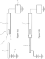
- FIG 1(a) Shown in figure 1(a) in schematic form is a known switch 1 for use in a high current application.
- the switch 1 comprises a first electrically conductive arm 2 connected to a voltage source 3. It further comprises a second electrically conductive arm 4 connected to a load 5, which in this application is an electric train.
- the second arm 4 ends in a connector 6 which comprises first and second spaced apart fingers 7,8.
- the two arms 2,4 are spaced apart and the switch 1 is in the open configuration.
- the first arm 2 In order to switch the switch 1 to the closed configuration the first arm 2 is moved towards the second arm 4 as shown in figure 1(b) . As the first arm 2 approaches the second arm 4 pre contact arcing occurs as shown and current starts to flow from the first arm 2 to the second arm 4.
- the switch comprises a first electrically conductive arm 11 which comprises an electrically conductive arcing portion 12 and an electrically conductive main portion 13.
- the arcing portion 12 comprises first and second spaced apart arcing fingers 14 pivotally connected to a base portion 15 by an arcing finger pivot 16.
- the main portion 13 comprises a plurality of pairs of main portion fingers 17, each pair of main portion fingers 17 being pivotally connected to the base portion 15 by a base portion pivot 18.
- the base portion 15 is shown connected to a load 19 which is in turn connected to earth 20.
- the electrical switch 10 further comprises a second electrically conductive arm 21.
- the second electrically conductive arm 21 comprises an electrically conductive body portion 22.
- the second arm 21 further comprises an electrically conductive wheel 23 which is connected to the body portion 22 by a wheel axle 24 which extends along a wheel axis. The wheel 23 is free to rotate about the wheel axis.
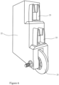
- the end of the second arm 21 proximate to the first arm 11 is shown in greater detail in figure 3 .
- the body portion 22 comprises a plurality of electrically conductive receiving fingers 25.
- Each receiving finger 25 terminates in an electrically taper 26.
- the taper 26 may be electrically insulating.
- the electrically conductive wheel 23 is sandwiched between contact washers 27.
- the contact washers 27 abut the body portion 22 ensuring a good electrical contact between the wheel 23 and the body portion 22.
- the contact washer 27 is cylindrical and arranged around the wheel axle 24.
- the wheel 23 is arranged around the contact washer 27.
- the contact washer 27 comprises an electrically conductive, preferably copper, disk defined by an outer edge 28. Extending through the center of the disk is a central aperture 29. A plurality of spaced apart first slots 30 extend from the central aperture 29 part way to the outer edge 28. A plurality of spaced apart second slots 31 extend from the outer edge 28 part way to the central aperture 29. The first slots 30 and second slots 31 are interdigitated. As can be seen in side view, the center of the washer 27 is slightly raised with respect to the outer edge 28 so that the washer 27 is slightly bowl shaped and matches the profile of the wheel 23.
- each contact washer 27 is centered on a face of the wheel 23 with the center of the central aperture 29 coaxial with the wheel axle 24.
- the switch 10 is shown in the open configuration with the first and second arms 11,21 spaced apart.
- the switch 10 further comprises a pivot mechanism 32 connected to each of the pairs of arcing fingers 14 and main potion fingers 17.
- the pivot mechanism 32 simultaneously pivots the pair of arcing fingers 14 and multiple pairs of main portion fingers 17 towards the second electrically conductive arm 21.
- the arcing fingers 14 approach the wheel 23 pre-contact arcing occurs between the arcing fingers 14 and wheel 23.
- the edge of the wheel 23 is received between the arcing fingers 14.
- the wheel 23 rotates around the wheel axis, so allowing pivoting to continue with little resistance.
- each pair of main portion fingers 17 slides onto a taper 26 and then onto a receiving finger 25.
- a significant portion of the current is flowing through the arcing fingers 14 and wheel 23.
- the remainder of the current is divided between each of the pairs of main portion fingers 17.
- the current flowing through a single pair of main portion fingers 17 to its associated receiving finger 25 is therefore relatively small and so the Lorentz force between the main portion fingers 17 and the receiving finger 25 is also small.
- the pivot mechanism 32 can therefore pull the main portion fingers 17 onto the receiving fingers 25 with relatively little force, so closing the switch 10.
- the switch 10 is designed such that the main portion fingers 17 slide onto the receiving fingers 25 shortly after the arcing fingers 14 engage the wheel 23.
- the time difference is of the order a few milliseconds so as to avoid overheating the arcing fingers 14 and contact washers 27.
- the switch 10 according to the invention can therefore be switched from the open configuration to the closed configuration (and vice versa) with relatively little force.
- the switch 10 is shown in the closed configuration in figure 5 .
- a further advantage of the switch 10 according to the invention is that the wheel 23 is not necessarily in the same orientation with respect to the remainder of the second arm 21 each time the switch 10 is opened or closed. The erosion of the wheel 23 caused by pre contact arcing is therefore spread around the periphery of the wheel 23 rather than concentrated at one spot.
- FIG. 6 Shown in figure 6 is the end of the second arm 21 of an alternative embodiment of the invention.
- the body portion 22 comprises a plurality of pairs of receiving fingers 25.
- the main portion 13 of the first arm 11 comprises a plurality of single main portion fingers 17 each pivotally connected to the base portion 15.
- the operation of this second embodiment is similar to that of the first embodiment only with the main portion fingers 17 being received between pairs of receiving fingers 25 rather than vice versa.
- the electrical switch 10 comprises a first electrically conductive arm 11.
- the first arm 11 comprises an electrically conductive arcing portion 12 and an electrically conductive main portion 13.
- the arcing portion 12 comprises a resiliently deformable rail 33 having a slot 34 running along its length.
- the rail 33 is connected to a base portion 15.
- the main portion 13 comprises a plurality of main portion fingers 17 fixedly extending from the base portion 15.
- the switch 10 further comprises a second electrically conductive arm 21.
- the second arm 21 comprises a body portion 22. Connected to the body portion 22 by a wheel axle 24 which extends along a wheel axis is an electrically conductive wheel 23. The wheel 23 is free to rotate about the wheel axle 24.
- the body portion 22 comprises a plurality of receiving fingers 25 extending towards the first electrically conductive arm 11.
- the switch 10 further comprises a displacement mechanism 35 connected to the first arm 11.
- the displacement mechanism 35 is adapted to linearly displace the first arm 11 towards and away from the second arm 21.
- the switch 10 is shown in the open configuration with the first and second arms 11,21 spaced apart.
- the displacement mechanism 35 displaces the first arm 11 towards the second arm 21 until the wheel 23 engages the slot 34 running along the length of the rail 33.
- the switch 10 can be switched between open and closed configurations with relatively little force so making the switch 10 reliable and inexpensive to manufacture.
- the electrical switch system 40 comprises an electrical switch 10 as previously described.
- a power supply 41 Connected to one arm 11,21 is a power supply 41.
- the power supply 41 can provide a high current, typically in the range 50,000 to 200,000 Amps, more preferably in the range 80,000 - 150,000 Amps. More preferably the current is in the range 100,000 to 140,000 Amps.
- the other arm 11,21 of the switch 10 is connected to a load 42 which is in turn connected to earth 43.
- the load 42 is typically an electrically powered vehicle such as a train but the invention is not so limited.
- the switch 10 comprises a plurality of pairs of main portion fingers 17. In an alternative embodiment the switch 10 comprises a single pair of main portion fingers 17.
- the switch 10 can be employed in both AC and DC systems.
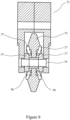
- FIG. 9 Shown in figure 9 in vertical cross section is a second arm 21 of a further embodiment of an electrical switch10 according to the invention.
- the electrically conductive wheel 23 is arranged on a wheel axle 24 which in turn is connected to the body portion 22.
- the wheel 23 has a recess 36 in each face proximate to the wheel axle 24.
- the electrical switch 10 further comprises a pair of electrically conductive axle collars 37 arranged around the wheel axle 24.
- the contact washers 27 are initially flat. As the wheel 23, wheel axle 24 and axle collars 37 are assembled the axle collars 37 deform the contact washers 27 into the desired shape.
Landscapes
- Arc-Extinguishing Devices That Are Switches (AREA)
- Rotary Switch, Piano Key Switch, And Lever Switch (AREA)
Description
- The present invention relates to an electrical switch. More particularly, but not exclusively, the present invention relates to an electrical switch comprising first and second arms, the second arm comprising a wheel, the switch being adapted such that as the switch closes an arcing portion of the first arm contacts the wheel before a main portion of the first arm contacts a body portion of the second arm. The present invention also relates to an electrical switch system. More particularly, but not exclusively, the present invention relates to an electrical switch system comprising an electrical switch, one arm of the electrical switch being connected to a power supply, the other arm being connected to a load.
- Electrical switches for use in high current applications are known. Such switches are typically designed to carry currents of up to 10,000 Amps. However, if the switch is closed onto a faulty load the switch could be required to carry a current in the range 100,000 to 150,000 Amps even if only briefly. An example of such an application is in the field of electric railways.
-
DE6811150U discloses a coaxial two-way switch with a rotatable contact device which can be moved into at least two switching positions, in particular via a magnetic drive, and which is designed as an insulating disc with strip conductors applied on both sides, with which fork contacts which are connected to the inner conductor of the relevant coaxial conductor section interact. -
FR2891395 - Document
EP1961 027 discloses a high voltage circuit breaker having fixed contacts on a carrier and movable contacts that move on shaft. The fixed contacts have a have permanent magnets that operate to extinguish any arcing between the contacts. - A particular problem associated with switches used in high current applications is the Lorentz force.
- As the arm of the switch approaches an electrical contact to close a circuit pre contact arcing occurs and current starts to flow. The Lorentz force pinches the contact and the switch arm together and considerable force has to be employed to fully insert the switch arm into the contact. Because of this such switches tend to be large as they must include a driving mechanism to provide the necessary force to drive the arm home into the contact. Typically large springs or mechanical or hydraulic rams are employed. Use of such driving mechanisms tends to cause the arm or contact to deform or wear away so reducing the life of the switch. Typically such switches can only be used less than ten times before they need to be replaced at considerable cost.
- A further problem with such known switches is that when pre contact arcing occurs, it always occurs between the same two points on the switch arm and contact. This erodes the switch arm and contact, further reducing the lifetime of the switch.
- Both of these problems are particularly severe in the case of high current DC switches. This is due to the high rate of increase of the DC current, typically at a rate of around 40kA/ms.
- The current invention seeks to overcome the problems of the prior art.
- Accordingly,the present invention provides a electrical switch according to claim 1.
- Only a relatively small force needs to be used to open and close the switch of the current invention.
- Further, pre contact arcing does not always occur between the same points on the wheel and arcing portion. The switch according to the invention therefore has a considerably longer lifespan than known switches.
- Preferably the main portion comprises at least one pair of spaced apart main portion fingers, the body portion being adapted to be received between the main portion fingers.
- Preferably the electrical switch further comprises at least one electrically conductive contact washer having a central aperture, the contact washer being arranged on a face of the wheel.
- Preferably the wheel is sandwiched between contact washers.
- Preferably the contact washer comprises a plurality of spaced apart first slots extending from the central aperture part way to the outer edge of the washer.
- Preferably the contact washer comprises a plurality of spaced apart second slots extending from the outer edge of the washer part way to the central aperture.
- Preferably the first slots are interdigitated with the second slots.
- In a further aspect of the invention there is provided an electrical switch system comprising
- an electrical switch as claimed in any one of claims 1 to 7; and,
- a power supply connected to one of the first and second arms.
- Preferably the electrical switch system further comprises a load connected to the other arm.
- Preferably the load is an electric vehicle.
- The present invention will now be described by way of example only and not in any limitative sense with reference to the accompanying drawings in which
-
Figures 1(a) to 1(d) show a known electrical switch for use in a high current application in schematic form. -
Figure 2 shows a first embodiment of an electrical switch according to the invention; -
Figure 3 shows the end of the second arm of the switch offigure 1 ; -
Figures 4(a) and 4(b) show the contact washer of the electrical switch offigure 1 ; -
Figure 5 shows the switch offigure 1 in the closed configuration; -
Figure 6 shows the second arm of a further embodiment of a switch according to the invention; -
Figure 7 shows an example of a switch not falling within the scope of the invention; -
Figure 8 shows an embodiment of an electrical switch system according to the invention; and, -
Figure 9 shows, in vertical cross section, the second arm of a further embodiment of a switch according to the invention. - Shown in
figure 1(a) in schematic form is a known switch 1 for use in a high current application. The switch 1 comprises a first electricallyconductive arm 2 connected to a voltage source 3. It further comprises a second electricallyconductive arm 4 connected to a load 5, which in this application is an electric train. Thesecond arm 4 ends in a connector 6 which comprises first and second spaced apartfingers 7,8. Infigure 1(a) the twoarms - In order to switch the switch 1 to the closed configuration the
first arm 2 is moved towards thesecond arm 4 as shown infigure 1(b) . As thefirst arm 2 approaches thesecond arm 4 pre contact arcing occurs as shown and current starts to flow from thefirst arm 2 to thesecond arm 4. - As the
first arm 2 is moved further it is received between the spacedapart fingers 7,8. At this point the current flowing from thefirst arm 2 and then through thefingers 7,8 causes thefingers 7,8 to be urged towards thefirst arm 2, so gripping thefirst arm 2, due to the Lorentz force. This is shown infigure 1(c) . - This gripping of the
first arm 2 by thefingers 7,8 produces significant friction between thefirst arm 2 andfingers 7,8. In order to push thefirst arm 2 fully home between thefingers 7,8 considerable force must be used, A spring 9 or other hydraulic or mechanical means is typically used to achieve this, as shown infigure 1(d) . - Shown in
figure 2 in perspective view is a first embodiment of anelectrical switch 10 according to the invention. The switch comprises a first electricallyconductive arm 11 which comprises an electricallyconductive arcing portion 12 and an electrically conductivemain portion 13. Thearcing portion 12 comprises first and second spaced apart arcingfingers 14 pivotally connected to abase portion 15 by an arcingfinger pivot 16. Themain portion 13 comprises a plurality of pairs ofmain portion fingers 17, each pair ofmain portion fingers 17 being pivotally connected to thebase portion 15 by abase portion pivot 18. Thebase portion 15 is shown connected to aload 19 which is in turn connected toearth 20. - The
electrical switch 10 further comprises a second electricallyconductive arm 21. The second electricallyconductive arm 21 comprises an electricallyconductive body portion 22. Thesecond arm 21 further comprises an electricallyconductive wheel 23 which is connected to thebody portion 22 by awheel axle 24 which extends along a wheel axis. Thewheel 23 is free to rotate about the wheel axis. - The end of the
second arm 21 proximate to thefirst arm 11 is shown in greater detail infigure 3 . As can be seen from this figure thebody portion 22 comprises a plurality of electrically conductive receivingfingers 25. Each receivingfinger 25 terminates in anelectrically taper 26. Thetaper 26 may be electrically insulating. The electricallyconductive wheel 23 is sandwiched betweencontact washers 27. Thecontact washers 27 abut thebody portion 22 ensuring a good electrical contact between thewheel 23 and thebody portion 22. In an alternative embodiment (not shown) thecontact washer 27 is cylindrical and arranged around thewheel axle 24. Thewheel 23 is arranged around thecontact washer 27. - An example of a
contact washer 27 is shown in plan view and side view infigures 4(a) and 4(b) . Thecontact washer 27 comprises an electrically conductive, preferably copper, disk defined by anouter edge 28. Extending through the center of the disk is acentral aperture 29. A plurality of spaced apartfirst slots 30 extend from thecentral aperture 29 part way to theouter edge 28. A plurality of spaced apartsecond slots 31 extend from theouter edge 28 part way to thecentral aperture 29. Thefirst slots 30 andsecond slots 31 are interdigitated. As can be seen in side view, the center of thewasher 27 is slightly raised with respect to theouter edge 28 so that thewasher 27 is slightly bowl shaped and matches the profile of thewheel 23. - Returning to
figure 3 , eachcontact washer 27 is centered on a face of thewheel 23 with the center of thecentral aperture 29 coaxial with thewheel axle 24. - Returning to
figure 2 , theswitch 10 is shown in the open configuration with the first andsecond arms switch 10 further comprises apivot mechanism 32 connected to each of the pairs of arcingfingers 14 andmain potion fingers 17. In order to switch theswitch 10 from the open configuration to a closed configuration thepivot mechanism 32 simultaneously pivots the pair of arcingfingers 14 and multiple pairs ofmain portion fingers 17 towards the second electricallyconductive arm 21. As the arcingfingers 14 approach thewheel 23 pre-contact arcing occurs between the arcingfingers 14 andwheel 23. As pivoting continues the edge of thewheel 23 is received between the arcingfingers 14. Current flows from the arcingfingers 14 through thewheel 23 andcontact washers 27 to thebody portion 22 of thesecond arm 21. This current flow causes the arcingfingers 14 to grip thewheel 23 firmly. As pivoting continues further thewheel 23 rotates around the wheel axis, so allowing pivoting to continue with little resistance. - As pivoting continues further each pair of
main portion fingers 17 slides onto ataper 26 and then onto a receivingfinger 25. A significant portion of the current is flowing through the arcingfingers 14 andwheel 23. The remainder of the current is divided between each of the pairs ofmain portion fingers 17. The current flowing through a single pair ofmain portion fingers 17 to its associated receivingfinger 25 is therefore relatively small and so the Lorentz force between themain portion fingers 17 and the receivingfinger 25 is also small. Thepivot mechanism 32 can therefore pull themain portion fingers 17 onto the receivingfingers 25 with relatively little force, so closing theswitch 10. - The
switch 10 is designed such that themain portion fingers 17 slide onto the receivingfingers 25 shortly after the arcingfingers 14 engage thewheel 23. Typically the time difference is of the order a few milliseconds so as to avoid overheating the arcingfingers 14 andcontact washers 27. - The
switch 10 according to the invention can therefore be switched from the open configuration to the closed configuration (and vice versa) with relatively little force. Theswitch 10 is shown in the closed configuration infigure 5 . A further advantage of theswitch 10 according to the invention is that thewheel 23 is not necessarily in the same orientation with respect to the remainder of thesecond arm 21 each time theswitch 10 is opened or closed. The erosion of thewheel 23 caused by pre contact arcing is therefore spread around the periphery of thewheel 23 rather than concentrated at one spot. - Shown in
figure 6 is the end of thesecond arm 21 of an alternative embodiment of the invention. In this embodiment thebody portion 22 comprises a plurality of pairs of receivingfingers 25. Themain portion 13 of thefirst arm 11 comprises a plurality of singlemain portion fingers 17 each pivotally connected to thebase portion 15. The operation of this second embodiment is similar to that of the first embodiment only with themain portion fingers 17 being received between pairs of receivingfingers 25 rather than vice versa. - Shown in
figure 7 is an example of anelectrical switch 10 not falling within the scope of the invention. Theelectrical switch 10 comprises a first electricallyconductive arm 11. Thefirst arm 11 comprises an electricallyconductive arcing portion 12 and an electrically conductivemain portion 13. The arcingportion 12 comprises a resilientlydeformable rail 33 having aslot 34 running along its length. Therail 33 is connected to abase portion 15. Themain portion 13 comprises a plurality ofmain portion fingers 17 fixedly extending from thebase portion 15. - The
switch 10 further comprises a second electricallyconductive arm 21. Thesecond arm 21 comprises abody portion 22. Connected to thebody portion 22 by awheel axle 24 which extends along a wheel axis is an electricallyconductive wheel 23. Thewheel 23 is free to rotate about thewheel axle 24. Thebody portion 22 comprises a plurality of receivingfingers 25 extending towards the first electricallyconductive arm 11. - The
switch 10 further comprises adisplacement mechanism 35 connected to thefirst arm 11. Thedisplacement mechanism 35 is adapted to linearly displace thefirst arm 11 towards and away from thesecond arm 21. - The
switch 10 is shown in the open configuration with the first andsecond arms switch 10 to the closed configuration thedisplacement mechanism 35 displaces thefirst arm 11 towards thesecond arm 21 until thewheel 23 engages theslot 34 running along the length of therail 33. As thefirst arm 11 is displaced further thewheel 23 rotates and therail 33 is deformed until the receivingfingers 25 are received between themain portion fingers 17, so closing theswitch 10. As before, theswitch 10 can be switched between open and closed configurations with relatively little force so making theswitch 10 reliable and inexpensive to manufacture. - Shown in
figure 8 is an electrical switch system 40 according to the invention. The electrical switch system 40 comprises anelectrical switch 10 as previously described. Connected to onearm power supply 41. Thepower supply 41 can provide a high current, typically in the range 50,000 to 200,000 Amps, more preferably in the range 80,000 - 150,000 Amps. More preferably the current is in the range 100,000 to 140,000 Amps. Theother arm switch 10 is connected to aload 42 which is in turn connected toearth 43. Theload 42 is typically an electrically powered vehicle such as a train but the invention is not so limited. - In the embodiment of
figure 2 theswitch 10 comprises a plurality of pairs ofmain portion fingers 17. In an alternative embodiment theswitch 10 comprises a single pair ofmain portion fingers 17. - The
switch 10 can be employed in both AC and DC systems. - Shown in
figure 9 in vertical cross section is asecond arm 21 of a further embodiment of an electrical switch10 according to the invention. The electricallyconductive wheel 23 is arranged on awheel axle 24 which in turn is connected to thebody portion 22. Thewheel 23 has arecess 36 in each face proximate to thewheel axle 24. Theelectrical switch 10 further comprises a pair of electricallyconductive axle collars 37 arranged around thewheel axle 24. In this embodiment thecontact washers 27 are initially flat. As thewheel 23,wheel axle 24 andaxle collars 37 are assembled theaxle collars 37 deform thecontact washers 27 into the desired shape.
Claims (10)
- A electrical switch (10) comprising a first electrically conductive arm (11) comprising a first electrically conductive arcing portion (12) and an electrically conductive main portion (13); a second electrically conductive arm (21) comprising an electrically conductive body portion (22)at least one of the first and second arms (11, 21) being adapted to be displaced relative to the other to move the switch (10) between an open configuration in which the first and second arms (11, 21) are spaced apart and a closed configuration in which the main portion (13) is in contact with the body portion (22);the electrical switch (10) further comprising a pivot mechanism (32) to pivot the arcing portion (12) and the main portion (13) into contact with the body portion (22)characterised in thatthe second electrically conductive arm (21) further comprises an electrically conductive wheel (23) connected to the body portion (22) by a wheel axle (24) which extends along a wheel axis, the wheel (23) being free to rotate about the wheel axis, the wheel (23) being in electrical contact with the body portion (22), wherein in the closed configuration the arcing portion (12) is in contact with the wheel (23), the switch (10) being adapted such that as the switch (10) is switched from the open configuration to the closed configuration the arcing portion (12) contacts the wheel (23) before the main portion (13) contacts the body portion (22); wherein the arcing portion (12) comprises at least one pair of spaced apart arcing fingers (14), the wheel (23) being adapted to be received between the fingers (14), and in that the pivot mechanism (32) is adapted to pivot the arcing portion (21) into contact with the wheel (23).
- An electrical switch (10) as claimed in claim 1, wherein the main portion (13) comprises at least one pair of spaced apart main portion fingers (17), the body portion (22) being adapted to be received between the main portion fingers (17).
- An electrical switch (10) as claimed in either of claims 1 or 2, further comprising at least one electrically conductive contact washer (27) having a central aperture (29), the contact washer (27) being arranged on a face of the wheel (23).
- An electrical switch (10) as claimed in claim 3, wherein the wheel (23) is sandwiched between contact washers (27).
- An electrical switch (10) as claimed in either of claims 3 or 4, wherein the contact washer (27) comprises a plurality of spaced apart first slots (30) extending from the central aperture (29) part way to the outer edge (28) of the washer (27).
- An electrical switch (10) as claimed in any one of claims 3 to 5, wherein the contact washer (27) comprises a plurality of spaced apart second slots (31) extending from the outer edge (28) of the washer (27) part way to the central aperture (29).
- An electrical switch (10) as claimed in claim 6 when dependent on claim 5, wherein the first slots (30) are interdigitated with the second slots (31).
- An electrical switch system (40) comprisingan electrical switch (10) as claimed in any one of claims 1 to 7; and,a power supply (41) connected to one of the first and second arms (11, 21).
- An electrical switch system (40) as claimed in claim 8 further comprising a load (19, 42) connected to the other arm (21, 11).
- An electrical switch system (40) as claimed in claim 9, wherein the load (19) is an electric vehicle.
Applications Claiming Priority (2)
| Application Number | Priority Date | Filing Date | Title |
|---|---|---|---|
| GB1821167.2A GB2580174B (en) | 2018-12-23 | 2018-12-23 | An electrical switch and an electrical switch system |
| PCT/GB2019/053687 WO2020136372A1 (en) | 2018-12-23 | 2019-12-23 | An electrical switch and an electrical switch system |
Publications (2)
| Publication Number | Publication Date |
|---|---|
| EP3899997A1 EP3899997A1 (en) | 2021-10-27 |
| EP3899997B1 true EP3899997B1 (en) | 2024-10-30 |
Family
ID=65364430
Family Applications (1)
| Application Number | Title | Priority Date | Filing Date |
|---|---|---|---|
| EP19831864.4A Active EP3899997B1 (en) | 2018-12-23 | 2019-12-23 | An electrical switch and an electrical switch system |
Country Status (4)
| Country | Link |
|---|---|
| EP (1) | EP3899997B1 (en) |
| CN (1) | CN113454741B (en) |
| GB (1) | GB2580174B (en) |
| WO (1) | WO2020136372A1 (en) |
Citations (1)
| Publication number | Priority date | Publication date | Assignee | Title |
|---|---|---|---|---|
| EP1961027B1 (en) * | 2005-12-13 | 2013-11-13 | Siemens Aktiengesellschaft | Load interrupter for an encapsulated switchgear and permanent magnet system for a load interrupter |
Family Cites Families (12)
| Publication number | Priority date | Publication date | Assignee | Title |
|---|---|---|---|---|
| GB479315A (en) * | 1936-12-31 | 1938-02-03 | William Train Gray | Improvements relating to electric controllers |
| DE1181803B (en) * | 1959-06-29 | 1964-11-19 | Licentia Gmbh | Connection switch for transformers |
| DE6811150U (en) * | 1968-12-12 | 1969-08-14 | Spinner Gmbh Elektrotech | COAXIAL TWO-WAY SWITCH |
| CH498548A (en) * | 1969-10-31 | 1970-10-31 | Contraves Ag | Board with printed conductors for a switch |
| EP0010112A1 (en) * | 1978-10-17 | 1980-04-30 | ATELIERS DE CONSTRUCTIONS ELECTRIQUES DE CHARLEROI (ACEC) Société Anonyme | Electrical devices such as a commutator, with contacts arranged around the axis of a rotary cam |
| CN2360920Y (en) * | 1998-07-16 | 2000-01-26 | 张韬 | Rolling inserting contact mechanism |
| FR2852443B1 (en) * | 2003-03-11 | 2009-12-04 | Dav | SWITCH-CONTROLLED SWITCHING DEVICE AND ITS IMPLEMENTATION IN A DISPLAY CONTROL CIRCUIT |
| FR2891395B1 (en) * | 2005-09-28 | 2007-11-30 | Socomec Sa Sa | CUTTING MODULE FOR ELECTRICAL APPARATUS AND ELECTRIC APPARATUS EQUIPPED WITH SUCH A MODULE |
| DE102011118418B4 (en) * | 2011-11-12 | 2015-07-16 | Ellenberger & Poensgen Gmbh | switching system |
| CN102403161B (en) * | 2012-01-12 | 2014-05-14 | 沈阳华德海泰电器有限公司 | Three-station switch with capability of breaking bus transfer current |
| CN103871758A (en) * | 2012-12-12 | 2014-06-18 | 施耐德电器工业公司 | Rotary contact used for middle-and-high voltage breaker or switch |
| DE102013002155A1 (en) * | 2012-12-15 | 2014-07-03 | Brose Fahrzeugteile GmbH & Co. Kommanditgesellschaft, Würzburg | Electric motor with thermal fuse |
-
2018
- 2018-12-23 GB GB1821167.2A patent/GB2580174B/en active Active
-
2019
- 2019-12-23 CN CN201980083469.7A patent/CN113454741B/en active Active
- 2019-12-23 WO PCT/GB2019/053687 patent/WO2020136372A1/en not_active Ceased
- 2019-12-23 EP EP19831864.4A patent/EP3899997B1/en active Active
Patent Citations (1)
| Publication number | Priority date | Publication date | Assignee | Title |
|---|---|---|---|---|
| EP1961027B1 (en) * | 2005-12-13 | 2013-11-13 | Siemens Aktiengesellschaft | Load interrupter for an encapsulated switchgear and permanent magnet system for a load interrupter |
Also Published As
| Publication number | Publication date |
|---|---|
| GB201821167D0 (en) | 2019-02-06 |
| EP3899997A1 (en) | 2021-10-27 |
| WO2020136372A1 (en) | 2020-07-02 |
| GB2580174B (en) | 2022-10-26 |
| CN113454741A (en) | 2021-09-28 |
| CN113454741B (en) | 2024-11-26 |
| GB2580174A (en) | 2020-07-15 |
Similar Documents
| Publication | Publication Date | Title |
|---|---|---|
| US4791255A (en) | Twin break transfer switch | |
| AU2009265706B2 (en) | Disconnector for switchgear | |
| US9281138B2 (en) | Parallel type transfer switch contacts assemblies | |
| EP1442466B1 (en) | Low-voltage circuit breaker | |
| US20220285110A1 (en) | Medium voltage switching apparatus | |
| US9287060B2 (en) | Conversion device for converting a mechanical position into an electric state | |
| GB2580174A (en) | An electrical switch and an electrical switch system | |
| CN101896986B (en) | circuit breaker for switchgear | |
| CN113314359B (en) | Improved switchgear | |
| KR101704989B1 (en) | Movable contact of circuit breaker | |
| CN221040951U (en) | Switch contact system | |
| CN112534533B (en) | Disconnector with two contact parts that can move relative to each other | |
| US20250006438A1 (en) | Electrical switch arrangement for reducing arc energy and erosion in a contact system | |
| CN213340263U (en) | Moving contact assemblies and electrical switches | |
| KR100720791B1 (en) | Sequential Circuit Breaker Using Rotating Body With Contact | |
| CN217386916U (en) | Contact structure for automatic change-over switch | |
| HK40112080A (en) | Electrical switching apparatus for guiding high persistent currents and very high short‑circuit currents | |
| HK40112080B (en) | Electrical switching apparatus for guiding high persistent currents and very high short‑circuit currents | |
| US20250095927A1 (en) | Switching device for conducting high continuous currents and very high short-circuit currents | |
| EP4002408A1 (en) | Changeover switch | |
| KR20260032336A (en) | Multi-switch contactor assembly with a pre-charge relay | |
| JP2025133710A (en) | Multi-switch contactor assembly, system, and method | |
| GB2551307A (en) | Electrical switching assembly |
Legal Events
| Date | Code | Title | Description |
|---|---|---|---|
| STAA | Information on the status of an ep patent application or granted ep patent |
Free format text: STATUS: UNKNOWN |
|
| STAA | Information on the status of an ep patent application or granted ep patent |
Free format text: STATUS: THE INTERNATIONAL PUBLICATION HAS BEEN MADE |
|
| PUAI | Public reference made under article 153(3) epc to a published international application that has entered the european phase |
Free format text: ORIGINAL CODE: 0009012 |
|
| STAA | Information on the status of an ep patent application or granted ep patent |
Free format text: STATUS: REQUEST FOR EXAMINATION WAS MADE |
|
| 17P | Request for examination filed |
Effective date: 20210521 |
|
| AK | Designated contracting states |
Kind code of ref document: A1 Designated state(s): AL AT BE BG CH CY CZ DE DK EE ES FI FR GB GR HR HU IE IS IT LI LT LU LV MC MK MT NL NO PL PT RO RS SE SI SK SM TR |
|
| DAV | Request for validation of the european patent (deleted) | ||
| DAX | Request for extension of the european patent (deleted) | ||
| GRAP | Despatch of communication of intention to grant a patent |
Free format text: ORIGINAL CODE: EPIDOSNIGR1 |
|
| STAA | Information on the status of an ep patent application or granted ep patent |
Free format text: STATUS: GRANT OF PATENT IS INTENDED |
|
| INTG | Intention to grant announced |
Effective date: 20240109 |
|
| GRAJ | Information related to disapproval of communication of intention to grant by the applicant or resumption of examination proceedings by the epo deleted |
Free format text: ORIGINAL CODE: EPIDOSDIGR1 |
|
| STAA | Information on the status of an ep patent application or granted ep patent |
Free format text: STATUS: REQUEST FOR EXAMINATION WAS MADE |
|
| GRAP | Despatch of communication of intention to grant a patent |
Free format text: ORIGINAL CODE: EPIDOSNIGR1 |
|
| STAA | Information on the status of an ep patent application or granted ep patent |
Free format text: STATUS: GRANT OF PATENT IS INTENDED |
|
| INTC | Intention to grant announced (deleted) | ||
| INTG | Intention to grant announced |
Effective date: 20240531 |
|
| GRAS | Grant fee paid |
Free format text: ORIGINAL CODE: EPIDOSNIGR3 |
|
| GRAA | (expected) grant |
Free format text: ORIGINAL CODE: 0009210 |
|
| STAA | Information on the status of an ep patent application or granted ep patent |
Free format text: STATUS: THE PATENT HAS BEEN GRANTED |
|
| AK | Designated contracting states |
Kind code of ref document: B1 Designated state(s): AL AT BE BG CH CY CZ DE DK EE ES FI FR GB GR HR HU IE IS IT LI LT LU LV MC MK MT NL NO PL PT RO RS SE SI SK SM TR |
|
| REG | Reference to a national code |
Ref country code: GB Ref legal event code: FG4D |
|
| REG | Reference to a national code |
Ref country code: CH Ref legal event code: EP |
|
| REG | Reference to a national code |
Ref country code: IE Ref legal event code: FG4D |
|
| REG | Reference to a national code |
Ref country code: DE Ref legal event code: R096 Ref document number: 602019061235 Country of ref document: DE |
|
| REG | Reference to a national code |
Ref country code: LT Ref legal event code: MG9D |
|
| REG | Reference to a national code |
Ref country code: NL Ref legal event code: MP Effective date: 20241030 |
|
| PG25 | Lapsed in a contracting state [announced via postgrant information from national office to epo] |
Ref country code: PT Free format text: LAPSE BECAUSE OF FAILURE TO SUBMIT A TRANSLATION OF THE DESCRIPTION OR TO PAY THE FEE WITHIN THE PRESCRIBED TIME-LIMIT Effective date: 20250228 Ref country code: HR Free format text: LAPSE BECAUSE OF FAILURE TO SUBMIT A TRANSLATION OF THE DESCRIPTION OR TO PAY THE FEE WITHIN THE PRESCRIBED TIME-LIMIT Effective date: 20241030 Ref country code: IS Free format text: LAPSE BECAUSE OF FAILURE TO SUBMIT A TRANSLATION OF THE DESCRIPTION OR TO PAY THE FEE WITHIN THE PRESCRIBED TIME-LIMIT Effective date: 20250228 |
|
| PG25 | Lapsed in a contracting state [announced via postgrant information from national office to epo] |
Ref country code: FI Free format text: LAPSE BECAUSE OF FAILURE TO SUBMIT A TRANSLATION OF THE DESCRIPTION OR TO PAY THE FEE WITHIN THE PRESCRIBED TIME-LIMIT Effective date: 20241030 Ref country code: NL Free format text: LAPSE BECAUSE OF FAILURE TO SUBMIT A TRANSLATION OF THE DESCRIPTION OR TO PAY THE FEE WITHIN THE PRESCRIBED TIME-LIMIT Effective date: 20241030 |
|
| REG | Reference to a national code |
Ref country code: AT Ref legal event code: MK05 Ref document number: 1737786 Country of ref document: AT Kind code of ref document: T Effective date: 20241030 |
|
| PG25 | Lapsed in a contracting state [announced via postgrant information from national office to epo] |
Ref country code: BG Free format text: LAPSE BECAUSE OF FAILURE TO SUBMIT A TRANSLATION OF THE DESCRIPTION OR TO PAY THE FEE WITHIN THE PRESCRIBED TIME-LIMIT Effective date: 20241030 |
|
| PG25 | Lapsed in a contracting state [announced via postgrant information from national office to epo] |
Ref country code: ES Free format text: LAPSE BECAUSE OF FAILURE TO SUBMIT A TRANSLATION OF THE DESCRIPTION OR TO PAY THE FEE WITHIN THE PRESCRIBED TIME-LIMIT Effective date: 20241030 |
|
| PG25 | Lapsed in a contracting state [announced via postgrant information from national office to epo] |
Ref country code: NO Free format text: LAPSE BECAUSE OF FAILURE TO SUBMIT A TRANSLATION OF THE DESCRIPTION OR TO PAY THE FEE WITHIN THE PRESCRIBED TIME-LIMIT Effective date: 20250130 |
|
| PG25 | Lapsed in a contracting state [announced via postgrant information from national office to epo] |
Ref country code: AT Free format text: LAPSE BECAUSE OF FAILURE TO SUBMIT A TRANSLATION OF THE DESCRIPTION OR TO PAY THE FEE WITHIN THE PRESCRIBED TIME-LIMIT Effective date: 20241030 Ref country code: LV Free format text: LAPSE BECAUSE OF FAILURE TO SUBMIT A TRANSLATION OF THE DESCRIPTION OR TO PAY THE FEE WITHIN THE PRESCRIBED TIME-LIMIT Effective date: 20241030 Ref country code: GR Free format text: LAPSE BECAUSE OF FAILURE TO SUBMIT A TRANSLATION OF THE DESCRIPTION OR TO PAY THE FEE WITHIN THE PRESCRIBED TIME-LIMIT Effective date: 20250131 |
|
| PG25 | Lapsed in a contracting state [announced via postgrant information from national office to epo] |
Ref country code: PL Free format text: LAPSE BECAUSE OF FAILURE TO SUBMIT A TRANSLATION OF THE DESCRIPTION OR TO PAY THE FEE WITHIN THE PRESCRIBED TIME-LIMIT Effective date: 20241030 |
|
| PG25 | Lapsed in a contracting state [announced via postgrant information from national office to epo] |
Ref country code: RS Free format text: LAPSE BECAUSE OF FAILURE TO SUBMIT A TRANSLATION OF THE DESCRIPTION OR TO PAY THE FEE WITHIN THE PRESCRIBED TIME-LIMIT Effective date: 20250130 |
|
| PG25 | Lapsed in a contracting state [announced via postgrant information from national office to epo] |
Ref country code: SM Free format text: LAPSE BECAUSE OF FAILURE TO SUBMIT A TRANSLATION OF THE DESCRIPTION OR TO PAY THE FEE WITHIN THE PRESCRIBED TIME-LIMIT Effective date: 20241030 |
|
| PG25 | Lapsed in a contracting state [announced via postgrant information from national office to epo] |
Ref country code: MC Free format text: LAPSE BECAUSE OF FAILURE TO SUBMIT A TRANSLATION OF THE DESCRIPTION OR TO PAY THE FEE WITHIN THE PRESCRIBED TIME-LIMIT Effective date: 20241030 |
|
| PG25 | Lapsed in a contracting state [announced via postgrant information from national office to epo] |
Ref country code: DK Free format text: LAPSE BECAUSE OF FAILURE TO SUBMIT A TRANSLATION OF THE DESCRIPTION OR TO PAY THE FEE WITHIN THE PRESCRIBED TIME-LIMIT Effective date: 20241030 |
|
| PG25 | Lapsed in a contracting state [announced via postgrant information from national office to epo] |
Ref country code: EE Free format text: LAPSE BECAUSE OF FAILURE TO SUBMIT A TRANSLATION OF THE DESCRIPTION OR TO PAY THE FEE WITHIN THE PRESCRIBED TIME-LIMIT Effective date: 20241030 |
|
| PG25 | Lapsed in a contracting state [announced via postgrant information from national office to epo] |
Ref country code: RO Free format text: LAPSE BECAUSE OF FAILURE TO SUBMIT A TRANSLATION OF THE DESCRIPTION OR TO PAY THE FEE WITHIN THE PRESCRIBED TIME-LIMIT Effective date: 20241030 |
|
| PG25 | Lapsed in a contracting state [announced via postgrant information from national office to epo] |
Ref country code: SK Free format text: LAPSE BECAUSE OF FAILURE TO SUBMIT A TRANSLATION OF THE DESCRIPTION OR TO PAY THE FEE WITHIN THE PRESCRIBED TIME-LIMIT Effective date: 20241030 |
|
| PG25 | Lapsed in a contracting state [announced via postgrant information from national office to epo] |
Ref country code: CZ Free format text: LAPSE BECAUSE OF FAILURE TO SUBMIT A TRANSLATION OF THE DESCRIPTION OR TO PAY THE FEE WITHIN THE PRESCRIBED TIME-LIMIT Effective date: 20241030 |
|
| REG | Reference to a national code |
Ref country code: CH Ref legal event code: PL Ref country code: DE Ref legal event code: R097 Ref document number: 602019061235 Country of ref document: DE |
|
| PG25 | Lapsed in a contracting state [announced via postgrant information from national office to epo] |
Ref country code: LU Free format text: LAPSE BECAUSE OF NON-PAYMENT OF DUE FEES Effective date: 20241223 |
|
| PLBE | No opposition filed within time limit |
Free format text: ORIGINAL CODE: 0009261 |
|
| STAA | Information on the status of an ep patent application or granted ep patent |
Free format text: STATUS: NO OPPOSITION FILED WITHIN TIME LIMIT |
|
| PG25 | Lapsed in a contracting state [announced via postgrant information from national office to epo] |
Ref country code: SE Free format text: LAPSE BECAUSE OF FAILURE TO SUBMIT A TRANSLATION OF THE DESCRIPTION OR TO PAY THE FEE WITHIN THE PRESCRIBED TIME-LIMIT Effective date: 20241030 |
|
| 26N | No opposition filed |
Effective date: 20250731 |
|
| REG | Reference to a national code |
Ref country code: BE Ref legal event code: MM Effective date: 20241231 |
|
| PG25 | Lapsed in a contracting state [announced via postgrant information from national office to epo] |
Ref country code: BE Free format text: LAPSE BECAUSE OF NON-PAYMENT OF DUE FEES Effective date: 20241231 |
|
| PG25 | Lapsed in a contracting state [announced via postgrant information from national office to epo] |
Ref country code: CH Free format text: LAPSE BECAUSE OF NON-PAYMENT OF DUE FEES Effective date: 20241231 |
|
| PG25 | Lapsed in a contracting state [announced via postgrant information from national office to epo] |
Ref country code: IE Free format text: LAPSE BECAUSE OF NON-PAYMENT OF DUE FEES Effective date: 20241223 |
|
| PGFP | Annual fee paid to national office [announced via postgrant information from national office to epo] |
Ref country code: GB Payment date: 20251216 Year of fee payment: 7 |
|
| PGFP | Annual fee paid to national office [announced via postgrant information from national office to epo] |
Ref country code: IT Payment date: 20251216 Year of fee payment: 7 |
|
| PGFP | Annual fee paid to national office [announced via postgrant information from national office to epo] |
Ref country code: FR Payment date: 20251230 Year of fee payment: 7 |
|
| PGFP | Annual fee paid to national office [announced via postgrant information from national office to epo] |
Ref country code: DE Payment date: 20251216 Year of fee payment: 7 |