EP3899890B1 - Obscuration cloud generator - Google Patents
Obscuration cloud generator Download PDFInfo
- Publication number
- EP3899890B1 EP3899890B1 EP19828329.3A EP19828329A EP3899890B1 EP 3899890 B1 EP3899890 B1 EP 3899890B1 EP 19828329 A EP19828329 A EP 19828329A EP 3899890 B1 EP3899890 B1 EP 3899890B1
- Authority
- EP
- European Patent Office
- Prior art keywords
- container
- housing
- assembly
- obscuration cloud
- canister
- Prior art date
- Legal status (The legal status is an assumption and is not a legal conclusion. Google has not performed a legal analysis and makes no representation as to the accuracy of the status listed.)
- Active
Links
Images









Classifications
-
- G—PHYSICS
- G08—SIGNALLING
- G08B—SIGNALLING SYSTEMS, e.g. PERSONAL CALLING SYSTEMS; ORDER TELEGRAPHS; ALARM SYSTEMS
- G08B15/00—Identifying, scaring or incapacitating burglars, thieves or intruders, e.g. by explosives
- G08B15/02—Identifying, scaring or incapacitating burglars, thieves or intruders, e.g. by explosives with smoke, gas, or coloured or odorous powder or liquid
Definitions
- the present invention in some embodiments thereof, relates to an obscuration cloud generation device and, more particularly, but not exclusively, to a container for an obscuration cloud generating canister which is thermally isolating and releasable from the housing of the device.
- An obscuration cloud generator (e.g. a smoke screen generator or other particle cloud generator) may be triggered to generate an obscuration cloud by an alert condition in order to ward off an intruder.
- a smoke generator in response to a detection of an intruder, e.g. by a passive infrared detector (PIR) or other sensor, a smoke generator may be triggered to generate and release smoke to scare off the intruder.
- PIR passive infrared detector
- the obscuration cloud generator includes a canister which may generate an obscuration cloud by releasing a pressured gas and/or by generating and releasing a gas at high pressure by means of exothermic reaction.
- the canister may include a pair of electrical contacts which when provided with electrical power can trigger the canister to emit the visibility obscuring material.
- the present invention relates to an obscuration cloud generation device and a container for an obscuration cloud generating canister which is releasable from the housing of the device.
- a security system includes an obscuration cloud generating device.
- the present inventors have identified that such canisters are generally explosive and/or otherwise hazardous if improperly disposed or handled. Furthermore, the canister may require a tool to be accessed, making replacement of the canister difficult. Further disposal may require disassembly of the canister into its components to be separately handled thereafter.
- a container for holding an obscuration cloud generating canister for use in an obscuration cloud generation device which in some embodiments is wall mountable.
- the container may be easily removed from a housing of the device when canister replacement is to be performed. The removal of the container may be done via an opening, shaped and sized for this purpose, of the housing.
- the opening is covered by a door, which may be opened to allow canister emission of the composition from the device, and advantageously the same door also may be opened to allow removal of the container, thereby facilitating easy and/or intuitive access to the canister.
- the container may be held in the housing by a quick release mechanism that enables the container to be extracted from the housing easily, without tools, and by applying a relatively small force to facilitate removal by human hands.
- the quick release mechanism may include a handle having a closed position wherein the handle is laid inside a recess on the container, and an open position wherein a force may be applied to turn the handle and another force may be applied to pull the handle for releasing the container from the frame.
- the container may include a container frame and a container cover, both made of thermally insulating material, so the canister is mostly or entirely covered from all directions except from an opening at an end opposite to container cover.
- the canister is exposed through the opening, so the dissipation of heat created by emission when the canister is activated is directed to exit the device via the opening.
- the container may include internal protrusions for holding the canister and create an air gap between the container frame and the canister for further thermal insulation.
- the container includes guiding members, such as rails, that position the container when inserted into the housing.
- the guiding members are configured to keep the container at a specific radial orientation for electrical contacts on the container to engage with corresponding electrical contacts inside the housing.
- the container includes an angled outlet, so a composition emitted from the obscuration cloud generating canister is emitted in a defined direction that is off a longitudinal axis of the obscuration cloud generating canister.
- the container may include an alignment element for holding the obscuration cloud generating canister in a specific angular orientation inside the container, to maintain the direction of the emission.
- FIG. 1 is a schematic illustration of an exemplary obscuration cloud generation device, according to some embodiments of the present invention.
- Device 100 includes a mounting portion 120 removably attached to a housing 101.
- Housing 101 may be made, for example, from a high temperature thermoplastic.
- FIG. 2 is a schematic illustration of the exemplary obscuration cloud generation device of FIG. 1 , with the door open, according to some embodiments of the present invention.
- Housing 101 includes a door 102 and a frame 103.
- Device 100 also includes a container 104, which is removably held inside the frame 103.
- Frame 103 may for example have a cylindrical cavity for containing the container 104, which is also cylindrical.
- Container 104 holds a cylindrical obscuration cloud generating canister 110, for example within a cylindrical cavity in the container 104.
- the door 102 may be positioned at an opposite end of the frame 103 to the mounting portion 120, which may be directed downwardly in use.
- the cloud generating canister 110 When the cloud generating canister 110 is activated (by application of a predefined voltage across a pair of terminals extending from the canister cylinder), one or more gaseous jets of the cloud-forming composition are emitted from a bottom outlet 111 of the cloud generating canister 110 and push the door 102, by the pressure of the emission.
- the door therefore acts as the outlet of device 100.
- the door 102 is movable between a closed state for covering an opening 105 of the housing 101 and an open state for emission of the composition from the device 100 via the opening 105.
- the obscuration cloud generating canister 110 may be replaced after it has been activated and used up.
- the obscuration cloud generating canister 110 may be provided with or in the container 104 or may be acquired separately from the container, and may be provided with or in device 100 or separately from device 100.
- container 104 may be provided with device 100, with obscuration cloud generating canister 110 or separately.
- the container 104 includes the canister 110 during transport and/or storage.
- the opening 105 is shaped and sized to allow the container 104 to be extracted from the housing 101 through the opening 105 when the door 102 is open, to replace the obscuration cloud generating canister 110.
- FIGs. 3A and 3B are schematic illustrations of the exemplary obscuration cloud generation device of FIG. 1 , with the container removed, according to some embodiments of the present invention.
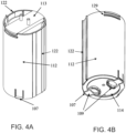
- FIGs. 4A and 4B are schematic illustrations of the container of the exemplary obscuration cloud generation device of FIG. 1 , according to some embodiments of the present invention.
- the container 104 may be removably held inside the frame 103 by a quick release mechanism 106.
- the quick release mechanism 106 may be located at an emission end of the container 104, which may be at the bottom of the device 100 in use, and is accessible via the door 102 when the door 102 is open.
- the quick release mechanism may include one or more members on the container 104 for selectively engaging or disengaging from a corresponding member on the housing 101 to respectively secure the container 104 in the housing 101 or enable withdrawal of the container 104 from the housing 101.
- the members may be, for example, protrusion(s) and corresponding recess(es).
- the quick release mechanism 106 includes one or more movable member(s) 109 having respective retractable protrusion(s) 107 (for example two) on the container 104 and one or more recess(es) 108 (for example two) on the housing 101.
- the protrusion(s) 107 are adjustably engaging or disengaging with the corresponding recess(es) 108.
- the recessing in the case of FIG. 3B being recessed spaces above respective inwardly protruding ridges 130 at the bottom of the housing (only one ridge is clearly visible in the figure, but the other may be located in a diametrically opposite location on the diameter of the frame 103).
- a circumferential recess may be provided by a region above in inwardly directed collar at the bottom of the housing 103, by the region having a wider inner diameter than that of the collar.
- the quick release mechanism includes one or more recess(es) on the container 104 for adjustably engaging or disengaging with a corresponding one or more retractable protrusion(s) on the housing 101.
- the protrusion(s) may be positioned on one or more movable member(s) (for example two) for selectively engaging or disengaging with recess(es) by a user.
- the movable members are clips having respective finger holes, wherein the quick release mechanism is released by applying squeezing force applicable by fingers in the finger holes to move the two movable members 109 closer together, thus pulling protrusions 107 to retract the protrusions 107 out of the recesses 108.
- the force required to overcome a holding force of the quick release mechanism 106 may be a squeezing force applicable by a person's hands, to allow easy removal of the container 104.
- the quick release mechanism may be operable without the need of a tool.
- quick release mechanisms may be used, for example a mechanism which locks the top of container 104 to an inner part of housing 101 by a rotational movement of a predefined amount.
- the container 104 includes a container frame 112 sized and shaped to accommodate the obscuration cloud generating canister 110, for example in an elongate cylindrical cavity.
- the container 104 may also include a container cover 113 releasably attached to the container frame 112 to close the end of the obscuration cloud generating canister which is at a top end opposite to the bottom outlet 111.
- the container cover 113 allows extracting the obscuration cloud generating canister 110 from the container 104, and prevents the obscuration cloud generating canister 110 from inadvertently falling out of the top of the container 104 when handled.
- the container cover 113 may be attached to the container frame 112 by a quick release mechanism based on similar concepts to the quick release mechanism 106 described above for the container 104 and the housing 101.
- the container cover 113 may include protrusions 128 (shown in FIG. 5B ) that are inserted into recesses 129 of container frame 112 (shown in FIG. 4B ), and which may be squeezed together to release the cover 113.
- This quick release mechanism allows opening the container 104 without a tool for accessing and extracting the obscuration cloud generating canister 110 from the frame 112 by sliding the canister 110 from the frame 112 without first needing to further disengage the canister 110 from the container 104.
- the canister 110 can be freely removed from the frame 112 once the quick release mechanism is disengaged to freely open the container 104. Further, the disengagement of the quick release mechanisms, both the one to remove the canister 110 from the container 104 and the one to remove the container 104 from the housing 101, may each be achieved by a single action.
- the container 104 includes one or more container guiding member(s) 122 for orienting the container 104 when the container 104 is inserted into the housing 101 through the opening and for holding position in the housing.
- the container guiding member(s) 122 may be guided by corresponding housing guiding member(s) 123 (shown in FIG. 3B ). Further, the container guiding member(s) 122 guide the container 104 in a specific radial orientation that engages interfering components of the release mechanism to automatically engage the release mechanism once the container 104 is fully inserted into the housing 101, and that electrically connects electrical contacts of the container 104 with corresponding electrical contacts of the housing 101.
- the respective guiding members on the container 104 and housing 101 each include a pair of rails, one pair fitting inside the other so that the container slides on the rails into the housing 101 to longitudinal slide of container 104 within the housing 101 and prevent from rotating inside the housing 101.
- one of the housing 101 and the container 104 includes a guiding member in the form of longitudinal rail and the other of the housing 101 and the container 104 includes a guiding member in the form of a longitudinal channel for receiving the rail to slide the rail along the channel.
- one or more rails on the housing may be or comprise a metallic rod associated with the housing 101.
- guiding members are included diagonally opposite locations on the container frame 112, but in other embodiments, only a single guiding member is included on the container frame.
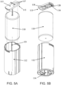
- FIGs. 5A and 5B are schematic illustrations of the container of the exemplary obscuration cloud generation device of FIG. 1 , with the obscuration cloud generating canister removed, according to some embodiments of the present invention.
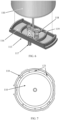
- FIG. 6 is a schematic illustration of the container cover of the exemplary obscuration cloud generation device of FIG. 1 , according to some embodiments of the present invention.
- the container cover 113 advantageously acts, not only as a cover, but also as an electrical adaptor to present contacts of the obscuration cloud generating canister 110 to an external side of the container 104.
- Conductors pass through the container cover 113 from an external surface 115 of the container (the surface further from the obscuration cloud generating canister 110) to an internal surface 116 of the container (the surface closer to the obscuration cloud generating canister 110).
- the conductors present respective external electrical connection terminals 117 fixed on the external surface 115 and corresponding internal electrical connection terminals 118 extending from the internal surface for connecting with corresponding canister contacts 119 of the obscuration cloud generating canister 110.
- the external electrical connection terminals 117 are connected into electrical contacts 131 (shown in FIG.
- the container cover 113 may include a jumper, which is releasably connected between the external electrical connection terminals 117, the jumper has a relatively low impedance (e.g. orders of magnitude smaller than an input impedance of the canister) to act as an electrical shunt.
- the shunt may be a conductor for short circuiting the canister contacts 119 to prevent unintended activation of the canister 104 by stray charge.
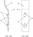
- FIGs. 12A and 12B An example of a jumper 150 that may be used for this purpose is illustrated in FIGs. 12A and 12B .
- the jumper 150 in this example is comprised of a flexible sheet of metal, having a pair of holes 152 for the receiving respective external electrical connection terminals 117 that extend from the container cover.
- the position of the external electrical connection terminals 117 when fitted within the jumper is indicated by broken lines in FIG. 12A .
- the metal is shaped to include springs 154 (e.g. part of the metal sheet acts as a spring) pushed into the respective external electrical connection terminals 117 to create a low resistance an electrical connection, e.g. a short circuit, between the external electrical connection terminals 117 to thereby mitigate against unintended activation of the canister 110.
- the jumper may also include a raised tab 156 for easy access and removal from the container cover.
- a jumper on a container 104 that holds the obscuration cloud generating canister 110 solves technical problem of providing the obscuration cloud generating canister 110 to an end user in such a manner that it is safe to transport and storage yet easy for the user to install.
- the obscuration cloud generating canister 110 may be transported and stored already installed in container 104 with a jumper that is easily removed when a user is ready to install the container 104 in the housing 101.
- the container frame 112 consists of a thermally insulating material, surrounding an entire length of the obscuration cloud generating canister 110.
- the container cover 113 comprises a thermally insulating material, which may be the same insulating material as the container frame 112.
- the thermally insulating material may have, for example, a melting point of 280°C or more.
- the thermally insulating material forms the housing 104 as a rigid casing for dimensional stability to restrict the position of the container 104 within the housing 101.
- the container frame 112 and/or the container cover 113 may be made entirely of a single material composition, or made of multiple materials.
- thermally insulating material may include high temperature thermoplastic.
- the material may comprise polycarbonate, and in some embodiments may also comprise fiberglass.
- the container frame 112 and/or container cover 113 may be made, for example, from a high temperature thermoplastic, having for example a melting temperature of at least 200 degrees, or in some embodiments at least 250 degrees, or in some embodiments at least 280 degrees, for example Makrolon ® 2858 manufactured by Covestro, which comprises polycarbonate and has a melting temperature between 280 °C and 320 °C.
- the housing frame 103 may be comprised of the same insulating material or a different material.
- the container 104 may also include a container opening 114, at an emission end opposite to the container cover 113, through which the obscuration cloud generating canister 110, when held in the container 104, is substantially exposed for directing dissipation of the heat of the emission via the container opening 114.
- substantially means that the majority of the bottom surface of the obscuration cloud generating canister 110 is thermally exposed, although in some embodiment some parts of the container opening 114 may be covered for example by the finger-hole clips.
- the portion of coverage at the periphery may be provided by the inwardly extending ridges 130, which in some embodiments cover no more than 10%, or in other embodiments no more than 5%, of the bottom surface of the canister. Therefore, the obscuration cloud generating canister 110 may be thermally insulated from all sides except at the container opening 114.
- the only opening in the obscuration cloud generating container 110 is on its bottom side, so that heat, generated by the obscuration cloud generating canister 110 in use, is encouraged to exit via the bottom side of the obscuration cloud generating canister 110 to efficiently exit the housing 101, in the same direction of heat flow, via the opening 105 in the bottom of the housing when the door 102 is open.
- FIG. 7 is a cross-section illustration of the container of the exemplary obscuration cloud generation device of FIG. 1 , according to some embodiments of the present invention.
- the container frame 112 includes internal protrusions 121 for holding the obscuration cloud generating canister 110 to create an air gap between the container frame and the obscuration cloud generating canister for further thermal insulation.
- the protrusions may be, for example, ribs that extend along a longitudinal dimension of the container.
- the internal protrusions 121 being longitudinal also allows easy insertion of the obscuration cloud generating canister 110 into the container 104 by sliding, as opposed for example to laterally extending internal protrusions.
- the container cover may partially cover the end of the obscuration cloud generating canister 110, as shown above with container cover of FIGs. 3 to 6 or may fully cover the end of the obscuration cloud generating canister 110, as shown in the container cover 113' of FIG. 8 , in accordance with some embodiments of the invention, to provide greater thermal insulation at the top of the container 104 and further encourage heat dissipation via the bottom opening of the container 104.
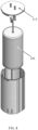
- FIGs. 9A and 9B are illustrations of the top part of the obscuration cloud generation device of FIG. 1 , showing the housing removed from a mounting portion 120 and respectively showing the batteries 123 inserted inside the housing and removed from the housing, respectively, according to some embodiments of the present invention.
- the batteries 123 are inserted inside a battery frame 126 that is held by container frame 103.
- the mounting portion 120 includes a bracket 124 for mounting with one or more mounting features 132 (e.g. screw holes) for mounting the bracket 124 to a vertical wall so the longitudinal axis of the housing 101 is parallel with the wall and in some implementations may be pointed downwards from a housing-holding part 125 of the mounting portion 120.
- mounting features 132 e.g. screw holes
- FIG. 10 is an exploded-view illustration of the top part of the exemplary obscuration cloud generation device of FIG. 1 , without the mounting portion 120, according to some embodiments of the present invention.
- FIG. 11 is a cross-section view illustration of the exemplary obscuration cloud generation device of FIG. 1 , according to some embodiments of the present invention.
- the device 100 may also include control components adapted to operate device 100 and more specifically configured to control the activation of the obscuration cloud generating canister 110.
- the control components may be located at an opposite end of frame 103 than the door 102, to be away where the majority of heat is dissipated from the device 100.
- the control components may be mounted for example on a printed circuit board (PCB) 127.
- the control components may include a processing circuitry which executes instructions stored in a memory.
- Using the device 100 in an exemplary method of replacing the obscuration cloud generating canister 110 without using any tools may include the following steps: Firstly, the door 102 is opened to access the quick release mechanism 106. In some embodiments, the door 102 is already in an open position as a result of an emission of the cloud obscuration material from the obscuration cloud generating canister 110, thus further reducing the number of steps needed to access the obscuration cloud generating canister 110. In other embodiments the door 102 can be at least partially opened by a controller and motor integrated into the housing 101 to open the door 102 upon receiving a command to do so.
- the quick release mechanism 106 is then released by a user, allowing the container 104 to slide free from the housing 101.
- the container 104 is opened by the user to allow the obscuration cloud generating canister 110 to be freely withdrawn from the container 104.
- the obscuration cloud generating canister 110 is thereby easily extracted and disposed (e.g. recycled) separately from the container 104.
- the container 104 may optionally be reused with a new canister, or a new assembly may be acquired having a new container with a new canister already included therein.
- the new or replacement container with a new obscuration cloud generating canister may then be slid inside housing 101, guided by the guiding members, and automatically locked into place by the quick release mechanism.
- Device 200 includes a housing 201 which includes a door 202 and a frame 203, and a container 104 which holds an obscuration cloud generating canister 210.
- FIG. 14 is a schematic illustration of the housing 201 of the device 200 of FIG. 13 , according to some embodiments of the present invention
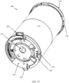
- FIG. 15 is a schematic illustration of an assembly 299 that is removable from the housing 201, according to some embodiments of the present invention
- FIG. 16 is a cross-section view illustration of the assembly 199 of FIG. 15 , according to some embodiments of the present invention.
- the assembly 299 includes a container 204 that holds the cloud generating canister 210.
- the assembly has an angled outlet 211 at a bottom end of the cloud generating canister 210.
- a composition emitted from the obscuration cloud generating canister 210 via the outlet 211 it is emitted in a defined direction that is off a longitudinal axis of the obscuration cloud generating canister 210, and at an angle relative to the bottom surface of the obscuration cloud generating canister 210.
- the angle of emission is shown by an arrow in FIG. 16 .
- the angle with respect to the bottom surface may be, for example, 60 degrees.
- the angle is predetermined to emit the composition downward and away from the wall, such that the emission appears perpendicular to the wall when viewed in plan. This prevents the emitted material from impacting and later being deposited on the door 102 and/or a wall behind the open door 202, as the emitted material is emitted to a direction away from the open door 202 which is vertical when open.
- the angled outlet 211 may include, for example, a tube, a partial angled cover and/or manifold.
- the outlet 211 may be metallic to withstand heat.
- the container 204 includes an alignment element 228 for holding the obscuration cloud generating canister 210 in a specific angular orientation inside the container 104.
- the specific orientation determines the direction that the composition is emitted from the outlet 211.
- the alignment element 228 may engage with a corresponding alignment member 229 on the obscuration cloud generating canister 210.
- the alignment element 228 includes a protrusion or a recess, and the alignment member 229 respectively includes a recess or a protrusion.
- alignment element 228 is a protrusion at the bottom part of the container 204 which is inserted into alignment member 229 which is a recess at the bottom of obscuration cloud generating canister 210.
- the container 204 includes a container body 212, a container cover 213, and/or a container bottom part 214.
- FIG. 17 is a schematic illustration of the container 104 of FIG. 15 showing the container cover 213 and the container bottom part 214 separated from the container body, according to some embodiments of the present invention.
- the alignment element 228 may be included in the container body 212, the container cover 213, and/or the container bottom part 214. However, in the exemplified embodiment, the alignment element 228 is included in the container body 212.
- the outlet 211 may be on the canister 210, on the bottom part 214 of the container body 212, or on a part therebetween. In some embodiments, the outlet 211 is be provided on sheet metal held between the container body and the canister and that has a hole to receive the alignment member 228 therethrough and it fix its angular alignment.
- the container 204 includes one or more container guiding members 222 for orienting the container 204 when the container 204 is inserted into the housing 201.
- the guiding members 222 fit to and slide along respective longitudinal rails 205 of housing 201, thus aligning the container 204 in a specific angular orientation with respect to housing 201.
- the container guiding members 222 may be included in any other part of the container 204.
- each of the container guiding members 222 have different dimensions, corresponding to rails 205 having corresponding different dimensions. This prevents the container 204 from being inserted in the opposite orientation into the housing 201.
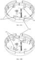
- FIGs. 18A and 18B are schematic illustrations of two views of the top of the container body 212 of the container 204 of FIG. 15 and a container cover 213 that caps the top end of the container body, according to some embodiments of the present invention.
- the container cover 213 connects to the container body 212 via an attachment/mating which determined the angular orientation between them.
- the container cover 213 includes four legs 223 that fit into holes 224 in container body 212.
- the legs 223 may be clipped inside holes 224 by a protrusion in each leg which is inserted through the top surface of the container body 212.
- the container cover 213 is oriented to the container body 212 via a keyed mating.
- the keyed mating is provided by protrusions 225 of container cover 213 that fit inside notches 226 of the container body 212. This determines the angular orientation between the container cover 213 and the container body 212.
- FIGs. 19A and 19B are schematic illustrations of the container cover of the container 204 of FIG. 15 , without and with canister connection terminals/contacts 219, according to some embodiments of the present invention.
- External electrical connection terminals 217 (shown in FIG. 18A ) carry power to the obscuration cloud generating canister 210 via the container cover 213.
- the external electrical connection terminals 217 feed through the cover 213 to present electrical connection terminals 218 on an underside of the cover 213.
- the external electrical connection terminals 217 are connected into electrical contacts 240 (shown in FIG. 14 ) of the housing 201, when container 204 is inserted into housing 201 to receive power from an electrical circuit within the housing to activate the canister 210 when needed.
- the external electrical connection terminals 217 are electrically continuous with the electrical connection terminals 218 located at the inner part of the container cover 213.
- the canister contacts 219 are screwed to the electrical connection terminals 218 to be held in electrical connection with the electrical connection terminals 218.
- the top part of the container body 212 includes an opening 227 to allow cables (not shown) connected to the screwed down electrical connection terminals 218 to pass into the obscuration cloud generating canister 210 held within the container 204.
- the container 204 is removably held inside the frame 203 by a quick release mechanism 206.
- the quick release mechanism 206 is included in the container bottom part 214.
- the container bottom part 214 includes bottom part protrusions 207, in the form of laterally extending wings, and which correspond to inwardly directed frame protrusions 208 of frame 203.
- the container bottom part 214 may be rotated (rotationally movable) with respect to the container body 212.
- the container bottom part 214 includes a handle 230 with which the container bottom part 214 may be rotated.
- the handle 230 has a closed position wherein the handle is laid inside a recess 231 on the container 204, and an open position wherein a force may be applied to turn the handle 230 to remove interference between the bottom part protrusions 207 and the frame protrusions 208, and another force, in this case a linear force, may be applied to pull the handle 230 for releasing the container 204 from the frame 203.
- FIGs. 20A and 20B are schematic illustrations of a bottom view of the container 204 of FIG. 15 , with different handle positions, according to some embodiments of the present invention.
- FIG. 20A shows the handle 230 in an open position and the bottom part protrusions 207 locked behind frame protrusions 208.
- FIG. 20B shows the container 204 after rotating the container bottom part 214 and releasing bottom part protrusions 207.
- FIG. 20B also shows the handle 230 in a closed position, to which the handle 230 may be pivoted from its open position. However in practice the handle 230 will generally only be placed into its closed position when the container 204 is it its locked configuration within the frame 203.
- At least one of the bottom part protrusions 207 and/or frame protrusions 208 includes an ending that prevents the container bottom part 214 from being overly rotated and the bottom part protrusions 207 from being accidentally released or over-rotated.
- a left one of the bottom part protrusions 207 includes an end 232 that protrudes in a direction away from the obscuration cloud generating canister 210 to interference with the corresponding the frame protrusion 208 so as to limit amount of rotation so that the container bottom part 214 cannot be rotated past the locked position.
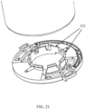
- FIG. 21 is a schematic illustrations of the container bottom part 214 of the container 204 of FIG. 15 , according to some embodiments of the present invention.
- the container bottom part 214 may include teeth 233 which fit into an opening at the bottom part of the container body 212. When inserted into the opening, the teeth 233 allow container bottom part 214 to be held to the container body yet rotated with respect to the container body 212.
- container body 212 includes two parts that may be opened and/or closed to extract and/or insert the obscuration cloud generating canister 210 into container 204.
- a first part 241 and a second part 242 engage with each other to hold the obscuration cloud generating canister 210 therebetween.
- the parts are keyed to predefine an angular orientation with respect to each other.
- the first part 241 includes one or more orientation teeth 243 (for example two) which are inserted into corresponding notches 244 in the second part 242 (shown in FIG. 16 ).
- composition or method may include additional ingredients and/or steps, but only if the additional ingredients and/or steps do not materially alter the basic and novel characteristics of the claimed composition or method.
- a compound or “at least one compound” may include a plurality of compounds, including mixtures thereof.
- range format is merely for convenience and brevity and should not be construed as an inflexible limitation on the scope of the invention. Accordingly, the description of a range should be considered to have specifically disclosed all the possible subranges as well as individual numerical values within that range. For example, description of a range such as from 1 to 6 should be considered to have specifically disclosed subranges such as from 1 to 3, from 1 to 4, from 1 to 5, from 2 to 4, from 2 to 6, from 3 to 6 etc., as well as individual numbers within that range, for example, 1, 2, 3, 4, 5, and 6. This applies regardless of the breadth of the range.
Landscapes
- Physics & Mathematics (AREA)
- General Physics & Mathematics (AREA)
- Details Of Rigid Or Semi-Rigid Containers (AREA)
- Casings For Electric Apparatus (AREA)
- Endoscopes (AREA)
- Packages (AREA)
Description
- This application claims the benefit of priority of
Israel Patent Application No. 263811 filed on 18 December, 2018 - This application is also related to co-filed PCT Patent Application entitled "OBSCURATION CLOUD GENERATOR" (Attorney Docket No. 78552), which claims the benefit of priority from
Israel Patent Application No. 263810 filed on 18 December, 2018 - The present invention, in some embodiments thereof, relates to an obscuration cloud generation device and, more particularly, but not exclusively, to a container for an obscuration cloud generating canister which is thermally isolating and releasable from the housing of the device.
- An obscuration cloud generator (e.g. a smoke screen generator or other particle cloud generator) may be triggered to generate an obscuration cloud by an alert condition in order to ward off an intruder. For example, in response to a detection of an intruder, e.g. by a passive infrared detector (PIR) or other sensor, a smoke generator may be triggered to generate and release smoke to scare off the intruder.
- The obscuration cloud generator includes a canister which may generate an obscuration cloud by releasing a pressured gas and/or by generating and releasing a gas at high pressure by means of exothermic reaction. The canister may include a pair of electrical contacts which when provided with electrical power can trigger the canister to emit the visibility obscuring material.
- Reference to any prior art in this specification is not an acknowledgement or suggestion that this prior art forms part of the common general knowledge in any jurisdiction, or globally, or that this prior art could reasonably be expected to be understood, regarded as relevant/or combined with other pieces of prior art by a person skilled in the art. An example of of a cloud generation device is described in
US 2017/209840 . - The invention is defined by the appended claims. Other aspects and/or embodiments of the present invention will be apparent from the description which follows. It will be appreciated that features and aspects of the present disclosure may be combined with other different aspects of the disclosure as appropriate, and not just in the specific illustrative combinations described herein.
- Unless otherwise defined, all technical and/or scientific terms used herein have the same meaning as commonly understood by one of ordinary skill in the art to which the invention pertains. Although methods and materials similar or equivalent to those described herein can be used in the practice or testing of embodiments of the invention, exemplary methods and/or materials are described below. In case of conflict, the patent specification, including definitions, will control. In addition, the materials, methods, and examples are illustrative only and are not intended to be necessarily limiting.
- Some embodiments of the invention are herein described, by way of example only, with reference to the accompanying drawings. With specific reference now to the drawings in detail, it is stressed that the particulars shown are by way of example and for purposes of illustrative discussion of embodiments of the invention. In this regard, the description taken with the drawings makes apparent to those skilled in the art how embodiments of the invention may be practiced. Like numerals in different figures are intended to refer to the same parts or, if required by the context, corresponding similar parts.
- In the drawings:
-
FIG. 1 is a schematic illustration of an exemplary obscuration cloud generation device, according to some embodiments of the present invention; -
FIG. 2 is a schematic illustration of the exemplary obscuration cloud generation device ofFIG. 1 , with the door open, according to some embodiments of the present invention; -
FIGs. 3A and 3B are schematic illustrations of the exemplary obscuration cloud generation device ofFIG. 1 , with the container removed, according to some embodiments of the present invention; -
FIGs. 4A and 4B are schematic illustrations of the container of the exemplary obscuration cloud generation device ofFIG. 1 , according to some embodiments of the present invention; -
FIGs. 5A and 5B are schematic illustrations of the container of the exemplary obscuration cloud generation device ofFIG. 1 , with the obscuration cloud generating canister removed, according to some embodiments of the present invention; -
FIG. 6 is a schematic illustration of the container cover of the exemplary obscuration cloud generation device ofFIG. 1 , according to some embodiments of the present invention; -
FIG. 7 is a cross-section illustration of the container of the exemplary obscuration cloud generation device ofFIG. 1 , according to some embodiments of the present invention; -
FIG. 8 is a schematic illustration of a container ofFIGs 3-7 , but having a full container cover, according to some embodiments of the present invention; -
FIGs. 9A and 9B are illustrations of the top part of the obscuration cloud generation device ofFIG. 1 , showing the housing removed from a mounting portion and respectively showing the batteries inserted inside the housing and removed from the housing, respectively, according to some embodiments of the present invention; -
FIG. 10 is an exploded-view illustration of the top part of the exemplary obscuration cloud generation device ofFIG. 1 , without the mounting portion, according to some embodiments of the present invention; -
FIG. 11 is a cross-section view illustration of the exemplary obscuration cloud generation device ofFIG. 1 , according to some embodiments of the present invention; and -
FIGs. 12A and 12B show an exemplary embodiment of a jumper, in a cross-sectional view and a top view respectively, that may be used with a container for holding an obscuration cloud generating canister, in accordance with some embodiments of the invention; -
FIG. 13 is a schematic illustration of another exemplary obscuration cloud generation device, according to some embodiments of the present invention; -
FIG. 14 is a schematic illustration of the housing of the device ofFIG. 13 , according to some embodiments of the present invention; -
FIG. 15 is a schematic illustration of an assembly that is removable from the housing of the device ofFIG. 13 , according to some embodiments of the present invention; -
FIG. 16 is a cross-section view illustration of the container ofFIG. 15 , according to some embodiments of the present invention; -
FIG. 17 is a schematic illustration of the container ofFIG. 15 showing the container cover and the container bottom part separated from the container body, according to some embodiments of the present invention; -
FIGs. 18A and 18B are schematic illustrations of two views of the top of the container body of the container ofFIG. 15 and a container cover that caps the top end of the container body, according to some embodiments of the present invention; -
FIGs. 19A and 19B are schematic illustrations of the container cover of the container ofFIG. 15 , without and with electrical connection terminals, according to some embodiments of the present invention; -
FIGs. 20A and 20B are schematic illustrations of a bottom view of the container ofFIG. 15 , with different handle positions, according to some embodiments of the present invention; -
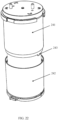
FIG. 21 is a schematic illustrations of the container bottom part of the container ofFIG. 15 , according to some embodiments of the present invention; -
FIG. 22 is a schematic illustrations of the container the container ofFIG. 15 , in an opened state, according to some embodiments of the present invention. - The present invention relates to an obscuration cloud generation device and a container for an obscuration cloud generating canister which is releasable from the housing of the device.
- A security system according to the invention includes an obscuration cloud generating device. The present inventors have identified that such canisters are generally explosive and/or otherwise hazardous if improperly disposed or handled. Furthermore, the canister may require a tool to be accessed, making replacement of the canister difficult. Further disposal may require disassembly of the canister into its components to be separately handled thereafter.
- According to the present invention, there is provided a container for holding an obscuration cloud generating canister for use in an obscuration cloud generation device, which in some embodiments is wall mountable. The container may be easily removed from a housing of the device when canister replacement is to be performed. The removal of the container may be done via an opening, shaped and sized for this purpose, of the housing. The opening is covered by a door, which may be opened to allow canister emission of the composition from the device, and advantageously the same door also may be opened to allow removal of the container, thereby facilitating easy and/or intuitive access to the canister.
- The container may be held in the housing by a quick release mechanism that enables the container to be extracted from the housing easily, without tools, and by applying a relatively small force to facilitate removal by human hands. The quick release mechanism may include a handle having a closed position wherein the handle is laid inside a recess on the container, and an open position wherein a force may be applied to turn the handle and another force may be applied to pull the handle for releasing the container from the frame.
- The container may include a container frame and a container cover, both made of thermally insulating material, so the canister is mostly or entirely covered from all directions except from an opening at an end opposite to container cover. The canister is exposed through the opening, so the dissipation of heat created by emission when the canister is activated is directed to exit the device via the opening. The container may include internal protrusions for holding the canister and create an air gap between the container frame and the canister for further thermal insulation.
- The container includes guiding members, such as rails, that position the container when inserted into the housing. The guiding members are configured to keep the container at a specific radial orientation for electrical contacts on the container to engage with corresponding electrical contacts inside the housing.
- The container includes an angled outlet, so a composition emitted from the obscuration cloud generating canister is emitted in a defined direction that is off a longitudinal axis of the obscuration cloud generating canister. The container may include an alignment element for holding the obscuration cloud generating canister in a specific angular orientation inside the container, to maintain the direction of the emission.
- Before explaining at least one embodiment of the invention in detail, it is to be understood that the invention is not necessarily limited in its application to the details of construction and the arrangement of the components and/or methods set forth in the following description and/or illustrated in the drawings and/or the Examples. The invention is capable of other embodiments or of being practiced or carried out in various other ways.
- Referring now to the drawings,
FIG. 1 is a schematic illustration of an exemplary obscuration cloud generation device, according to some embodiments of the present invention.Device 100 includes a mountingportion 120 removably attached to ahousing 101.Housing 101 may be made, for example, from a high temperature thermoplastic. - Reference is also made to
FIG. 2 , which is a schematic illustration of the exemplary obscuration cloud generation device ofFIG. 1 , with the door open, according to some embodiments of the present invention.Housing 101 includes adoor 102 and aframe 103.Device 100 also includes acontainer 104, which is removably held inside theframe 103.Frame 103 may for example have a cylindrical cavity for containing thecontainer 104, which is also cylindrical.Container 104 holds a cylindrical obscurationcloud generating canister 110, for example within a cylindrical cavity in thecontainer 104. Thedoor 102 may be positioned at an opposite end of theframe 103 to the mountingportion 120, which may be directed downwardly in use. - When the
cloud generating canister 110 is activated (by application of a predefined voltage across a pair of terminals extending from the canister cylinder), one or more gaseous jets of the cloud-forming composition are emitted from abottom outlet 111 of thecloud generating canister 110 and push thedoor 102, by the pressure of the emission. The door therefore acts as the outlet ofdevice 100. Thedoor 102 is movable between a closed state for covering anopening 105 of thehousing 101 and an open state for emission of the composition from thedevice 100 via theopening 105. - The obscuration
cloud generating canister 110 may be replaced after it has been activated and used up. The obscurationcloud generating canister 110 may be provided with or in thecontainer 104 or may be acquired separately from the container, and may be provided with or indevice 100 or separately fromdevice 100. Similarly,container 104 may be provided withdevice 100, with obscurationcloud generating canister 110 or separately. In some embodiments, however, thecontainer 104 includes thecanister 110 during transport and/or storage. Theopening 105 is shaped and sized to allow thecontainer 104 to be extracted from thehousing 101 through theopening 105 when thedoor 102 is open, to replace the obscurationcloud generating canister 110. - Reference is now made to
FIGs. 3A and 3B , which are schematic illustrations of the exemplary obscuration cloud generation device ofFIG. 1 , with the container removed, according to some embodiments of the present invention. Reference is also made toFIGs. 4A and 4B , which are schematic illustrations of the container of the exemplary obscuration cloud generation device ofFIG. 1 , according to some embodiments of the present invention. - The
container 104 may be removably held inside theframe 103 by aquick release mechanism 106. Thequick release mechanism 106 may be located at an emission end of thecontainer 104, which may be at the bottom of thedevice 100 in use, and is accessible via thedoor 102 when thedoor 102 is open. The quick release mechanism may include one or more members on thecontainer 104 for selectively engaging or disengaging from a corresponding member on thehousing 101 to respectively secure thecontainer 104 in thehousing 101 or enable withdrawal of thecontainer 104 from thehousing 101. The members may be, for example, protrusion(s) and corresponding recess(es). In some embodiments, as shown in the figures, thequick release mechanism 106 includes one or more movable member(s) 109 having respective retractable protrusion(s) 107 (for example two) on thecontainer 104 and one or more recess(es) 108 (for example two) on thehousing 101. The protrusion(s) 107 are adjustably engaging or disengaging with the corresponding recess(es) 108.The recessing in the case ofFIG. 3B being recessed spaces above respective inwardly protrudingridges 130 at the bottom of the housing (only one ridge is clearly visible in the figure, but the other may be located in a diametrically opposite location on the diameter of the frame 103). In other embodiments (not shown), a circumferential recess may be provided by a region above in inwardly directed collar at the bottom of thehousing 103, by the region having a wider inner diameter than that of the collar. - In other embodiments (not shown), the quick release mechanism includes one or more recess(es) on the
container 104 for adjustably engaging or disengaging with a corresponding one or more retractable protrusion(s) on thehousing 101. The protrusion(s) may be positioned on one or more movable member(s) (for example two) for selectively engaging or disengaging with recess(es) by a user. - In the exemplary embodiment shown in figures, the movable members are clips having respective finger holes, wherein the quick release mechanism is released by applying squeezing force applicable by fingers in the finger holes to move the two
movable members 109 closer together, thus pullingprotrusions 107 to retract theprotrusions 107 out of therecesses 108. The force required to overcome a holding force of thequick release mechanism 106 may be a squeezing force applicable by a person's hands, to allow easy removal of thecontainer 104. Thus, the quick release mechanism may be operable without the need of a tool. - In other embodiments, other quick release mechanisms may be used, for example a mechanism which locks the top of
container 104 to an inner part ofhousing 101 by a rotational movement of a predefined amount. - The
container 104 includes acontainer frame 112 sized and shaped to accommodate the obscurationcloud generating canister 110, for example in an elongate cylindrical cavity. Thecontainer 104 may also include acontainer cover 113 releasably attached to thecontainer frame 112 to close the end of the obscuration cloud generating canister which is at a top end opposite to thebottom outlet 111. Thecontainer cover 113 allows extracting the obscurationcloud generating canister 110 from thecontainer 104, and prevents the obscurationcloud generating canister 110 from inadvertently falling out of the top of thecontainer 104 when handled. - The
container cover 113 may be attached to thecontainer frame 112 by a quick release mechanism based on similar concepts to thequick release mechanism 106 described above for thecontainer 104 and thehousing 101. For example, in some embodiments, thecontainer cover 113 may include protrusions 128 (shown inFIG. 5B ) that are inserted intorecesses 129 of container frame 112 (shown inFIG. 4B ), and which may be squeezed together to release thecover 113. This quick release mechanism allows opening thecontainer 104 without a tool for accessing and extracting the obscurationcloud generating canister 110 from theframe 112 by sliding thecanister 110 from theframe 112 without first needing to further disengage thecanister 110 from thecontainer 104. Thus, thecanister 110 can be freely removed from theframe 112 once the quick release mechanism is disengaged to freely open thecontainer 104. Further, the disengagement of the quick release mechanisms, both the one to remove thecanister 110 from thecontainer 104 and the one to remove thecontainer 104 from thehousing 101, may each be achieved by a single action. - The
container 104 includes one or more container guiding member(s) 122 for orienting thecontainer 104 when thecontainer 104 is inserted into thehousing 101 through the opening and for holding position in the housing. The container guiding member(s) 122 may be guided by corresponding housing guiding member(s) 123 (shown inFIG. 3B ). Further, the container guiding member(s) 122 guide thecontainer 104 in a specific radial orientation that engages interfering components of the release mechanism to automatically engage the release mechanism once thecontainer 104 is fully inserted into thehousing 101, and that electrically connects electrical contacts of thecontainer 104 with corresponding electrical contacts of thehousing 101. - For example, in the illustrated embodiments, the respective guiding members on the
container 104 andhousing 101 each include a pair of rails, one pair fitting inside the other so that the container slides on the rails into thehousing 101 to longitudinal slide ofcontainer 104 within thehousing 101 and prevent from rotating inside thehousing 101. In other embodiments (not shown) one of thehousing 101 and thecontainer 104 includes a guiding member in the form of longitudinal rail and the other of thehousing 101 and thecontainer 104 includes a guiding member in the form of a longitudinal channel for receiving the rail to slide the rail along the channel. In any case, one or more rails on the housing may be or comprise a metallic rod associated with thehousing 101. In the illustrated embodiments, guiding members are included diagonally opposite locations on thecontainer frame 112, but in other embodiments, only a single guiding member is included on the container frame. - Reference is now made to
FIGs. 5A and 5B , which are schematic illustrations of the container of the exemplary obscuration cloud generation device ofFIG. 1 , with the obscuration cloud generating canister removed, according to some embodiments of the present invention. Reference is also made toFIG. 6 , which is a schematic illustration of the container cover of the exemplary obscuration cloud generation device ofFIG. 1 , according to some embodiments of the present invention. - In the illustrated embodiments, the
container cover 113 advantageously acts, not only as a cover, but also as an electrical adaptor to present contacts of the obscurationcloud generating canister 110 to an external side of thecontainer 104. Conductors pass through thecontainer cover 113 from anexternal surface 115 of the container (the surface further from the obscuration cloud generating canister 110) to aninternal surface 116 of the container (the surface closer to the obscuration cloud generating canister 110). The conductors present respective externalelectrical connection terminals 117 fixed on theexternal surface 115 and corresponding internalelectrical connection terminals 118 extending from the internal surface for connecting withcorresponding canister contacts 119 of the obscurationcloud generating canister 110. The externalelectrical connection terminals 117 are connected into electrical contacts 131 (shown inFIG. 11 ) of thehousing 101, whencontainer 104 is inserted intohousing 101. Electrical contacts may be positioned laterally to the side and touching each of the externalelectrical connection terminals 117. Each of the conductors may comprise a plurality of conductive parts or may be a single conductive part. Advantageously, thecontainer cover 113 may include a jumper, which is releasably connected between the externalelectrical connection terminals 117, the jumper has a relatively low impedance (e.g. orders of magnitude smaller than an input impedance of the canister) to act as an electrical shunt. For example the shunt may be a conductor for short circuiting thecanister contacts 119 to prevent unintended activation of thecanister 104 by stray charge. An example of ajumper 150 that may be used for this purpose is illustrated inFIGs. 12A and 12B . Thejumper 150 in this example is comprised of a flexible sheet of metal, having a pair ofholes 152 for the receiving respective externalelectrical connection terminals 117 that extend from the container cover. The position of the externalelectrical connection terminals 117 when fitted within the jumper is indicated by broken lines inFIG. 12A . The metal is shaped to include springs 154 (e.g. part of the metal sheet acts as a spring) pushed into the respective externalelectrical connection terminals 117 to create a low resistance an electrical connection, e.g. a short circuit, between the externalelectrical connection terminals 117 to thereby mitigate against unintended activation of thecanister 110. The jumper may also include a raisedtab 156 for easy access and removal from the container cover. - Using a jumper on a
container 104 that holds the obscurationcloud generating canister 110, solves technical problem of providing the obscurationcloud generating canister 110 to an end user in such a manner that it is safe to transport and storage yet easy for the user to install. In particular, the obscurationcloud generating canister 110 may be transported and stored already installed incontainer 104 with a jumper that is easily removed when a user is ready to install thecontainer 104 in thehousing 101. - In the illustrated embodiments, the
container frame 112 consists of a thermally insulating material, surrounding an entire length of the obscurationcloud generating canister 110. Optionally, thecontainer cover 113 comprises a thermally insulating material, which may be the same insulating material as thecontainer frame 112. The thermally insulating material may have, for example, a melting point of 280°C or more. The thermally insulating material forms thehousing 104 as a rigid casing for dimensional stability to restrict the position of thecontainer 104 within thehousing 101. Thecontainer frame 112 and/or thecontainer cover 113 may be made entirely of a single material composition, or made of multiple materials. For example, thermally insulating material may include high temperature thermoplastic. More specifically, in some embodiments the material may comprise polycarbonate, and in some embodiments may also comprise fiberglass. Thecontainer frame 112 and/orcontainer cover 113 may be made, for example, from a high temperature thermoplastic, having for example a melting temperature of at least 200 degrees, or in some embodiments at least 250 degrees, or in some embodiments at least 280 degrees, for example Makrolon® 2858 manufactured by Covestro, which comprises polycarbonate and has a melting temperature between 280 °C and 320 °C. Thehousing frame 103 may be comprised of the same insulating material or a different material. - The
container 104 may also include acontainer opening 114, at an emission end opposite to thecontainer cover 113, through which the obscurationcloud generating canister 110, when held in thecontainer 104, is substantially exposed for directing dissipation of the heat of the emission via thecontainer opening 114. In some embodiments, "substantially" means that the majority of the bottom surface of the obscurationcloud generating canister 110 is thermally exposed, although in some embodiment some parts of thecontainer opening 114 may be covered for example by the finger-hole clips. In some embodiments, the proportion of the bottom surface of thecanister 110 that are exposed as respectively at least 60%, at least 70%, and at least 80%, but optionally leaving a portion of coverage at a periphery of the bottom surface to assist in retaining the obscurationcloud generating canister 110 in thecontainer 104. For example, the portion of coverage at the periphery may be provided by the inwardly extendingridges 130, which in some embodiments cover no more than 10%, or in other embodiments no more than 5%, of the bottom surface of the canister. Therefore, the obscurationcloud generating canister 110 may be thermally insulated from all sides except at thecontainer opening 114. In some embodiments, the only opening in the obscurationcloud generating container 110 is on its bottom side, so that heat, generated by the obscurationcloud generating canister 110 in use, is encouraged to exit via the bottom side of the obscurationcloud generating canister 110 to efficiently exit thehousing 101, in the same direction of heat flow, via theopening 105 in the bottom of the housing when thedoor 102 is open. - Reference is now made to
FIG. 7 , which is a cross-section illustration of the container of the exemplary obscuration cloud generation device ofFIG. 1 , according to some embodiments of the present invention. - Optionally, the
container frame 112 includesinternal protrusions 121 for holding the obscurationcloud generating canister 110 to create an air gap between the container frame and the obscuration cloud generating canister for further thermal insulation. The protrusions may be, for example, ribs that extend along a longitudinal dimension of the container. Theinternal protrusions 121 being longitudinal also allows easy insertion of the obscurationcloud generating canister 110 into thecontainer 104 by sliding, as opposed for example to laterally extending internal protrusions. - The container cover may partially cover the end of the obscuration
cloud generating canister 110, as shown above with container cover ofFIGs. 3 to 6 or may fully cover the end of the obscurationcloud generating canister 110, as shown in the container cover 113' ofFIG. 8 , in accordance with some embodiments of the invention, to provide greater thermal insulation at the top of thecontainer 104 and further encourage heat dissipation via the bottom opening of thecontainer 104. -
Device 100 may also include a power source, such as one or more batteries. Reference is now made toFIGs. 9A and 9B , which are illustrations of the top part of the obscuration cloud generation device ofFIG. 1 , showing the housing removed from a mountingportion 120 and respectively showing thebatteries 123 inserted inside the housing and removed from the housing, respectively, according to some embodiments of the present invention. Thebatteries 123 are inserted inside abattery frame 126 that is held bycontainer frame 103. - The mounting
portion 120 includes abracket 124 for mounting with one or more mounting features 132 (e.g. screw holes) for mounting thebracket 124 to a vertical wall so the longitudinal axis of thehousing 101 is parallel with the wall and in some implementations may be pointed downwards from a housing-holdingpart 125 of the mountingportion 120. - Reference is now made to
FIG. 10 , which is an exploded-view illustration of the top part of the exemplary obscuration cloud generation device ofFIG. 1 , without the mountingportion 120, according to some embodiments of the present invention. Reference is also made toFIG. 11 , which is a cross-section view illustration of the exemplary obscuration cloud generation device ofFIG. 1 , according to some embodiments of the present invention. - As shown in these figures, the
device 100 may also include control components adapted to operatedevice 100 and more specifically configured to control the activation of the obscurationcloud generating canister 110. The control components may be located at an opposite end offrame 103 than thedoor 102, to be away where the majority of heat is dissipated from thedevice 100. The control components may be mounted for example on a printed circuit board (PCB) 127. The control components may include a processing circuitry which executes instructions stored in a memory. - Using the
device 100 in an exemplary method of replacing the obscurationcloud generating canister 110 without using any tools, may include the following steps: Firstly, thedoor 102 is opened to access thequick release mechanism 106. In some embodiments, thedoor 102 is already in an open position as a result of an emission of the cloud obscuration material from the obscurationcloud generating canister 110, thus further reducing the number of steps needed to access the obscurationcloud generating canister 110. In other embodiments thedoor 102 can be at least partially opened by a controller and motor integrated into thehousing 101 to open thedoor 102 upon receiving a command to do so. In any case, with thedoor 102 open, thequick release mechanism 106 is then released by a user, allowing thecontainer 104 to slide free from thehousing 101. When using a second release mechanism, on thecontainer 104, thecontainer 104 is opened by the user to allow the obscurationcloud generating canister 110 to be freely withdrawn from thecontainer 104. The obscurationcloud generating canister 110 is thereby easily extracted and disposed (e.g. recycled) separately from thecontainer 104. Thecontainer 104 may optionally be reused with a new canister, or a new assembly may be acquired having a new container with a new canister already included therein. - In any case the new or replacement container with a new obscuration cloud generating canister may then be slid inside
housing 101, guided by the guiding members, and automatically locked into place by the quick release mechanism. - Reference is now made to
FIG. 13 , which is a schematic illustration of another exemplary obscuration cloud generation device, according to some embodiments of the present invention.Device 200 includes ahousing 201 which includes adoor 202 and aframe 203, and acontainer 104 which holds an obscurationcloud generating canister 210. - Reference is also made to
FIG. 14 , which is a schematic illustration of thehousing 201 of thedevice 200 ofFIG. 13 , according to some embodiments of the present invention, and toFIG. 15 , which is a schematic illustration of anassembly 299 that is removable from thehousing 201, according to some embodiments of the present invention. Reference is also made toFIG. 16 , which is a cross-section view illustration of the assembly 199 ofFIG. 15 , according to some embodiments of the present invention. - Optionally, the
assembly 299 includes acontainer 204 that holds thecloud generating canister 210. The assembly has an angledoutlet 211 at a bottom end of thecloud generating canister 210. When a composition emitted from the obscurationcloud generating canister 210 via theoutlet 211, it is emitted in a defined direction that is off a longitudinal axis of the obscurationcloud generating canister 210, and at an angle relative to the bottom surface of the obscurationcloud generating canister 210. The angle of emission is shown by an arrow inFIG. 16 . The angle with respect to the bottom surface may be, for example, 60 degrees. With a wall-containingmounting surface 220 of thedevice 200 against a vertical wall, the longitudinal axis of the obscurationcloud generating canister 210 being vertical, and the cloud generating canister oriented to have theoutlet 211 at its bottom, the angle is predetermined to emit the composition downward and away from the wall, such that the emission appears perpendicular to the wall when viewed in plan. This prevents the emitted material from impacting and later being deposited on thedoor 102 and/or a wall behind theopen door 202, as the emitted material is emitted to a direction away from theopen door 202 which is vertical when open. Theangled outlet 211 may include, for example, a tube, a partial angled cover and/or manifold. Theoutlet 211 may be metallic to withstand heat. - Optionally, the
container 204 includes analignment element 228 for holding the obscurationcloud generating canister 210 in a specific angular orientation inside thecontainer 104. The specific orientation determines the direction that the composition is emitted from theoutlet 211. Thealignment element 228 may engage with acorresponding alignment member 229 on the obscurationcloud generating canister 210. For example, thealignment element 228 includes a protrusion or a recess, and thealignment member 229 respectively includes a recess or a protrusion. In this embodiment,alignment element 228 is a protrusion at the bottom part of thecontainer 204 which is inserted intoalignment member 229 which is a recess at the bottom of obscurationcloud generating canister 210. - Optionally, the
container 204 includes acontainer body 212, acontainer cover 213, and/or a containerbottom part 214. Reference is now made toFIG. 17 , which is a schematic illustration of thecontainer 104 ofFIG. 15 showing thecontainer cover 213 and the containerbottom part 214 separated from the container body, according to some embodiments of the present invention. Thealignment element 228 may be included in thecontainer body 212, thecontainer cover 213, and/or the containerbottom part 214. However, in the exemplified embodiment, thealignment element 228 is included in thecontainer body 212. - The
outlet 211 may be on thecanister 210, on thebottom part 214 of thecontainer body 212, or on a part therebetween. In some embodiments, theoutlet 211 is be provided on sheet metal held between the container body and the canister and that has a hole to receive thealignment member 228 therethrough and it fix its angular alignment. - The
container 204 includes one or morecontainer guiding members 222 for orienting thecontainer 204 when thecontainer 204 is inserted into thehousing 201. In this embodiment, there are twocontainer guiding members 222 in the form of two diametrically opposed notches or recesses included on the outer circumference ofcontainer cover 213. The guidingmembers 222 fit to and slide along respectivelongitudinal rails 205 ofhousing 201, thus aligning thecontainer 204 in a specific angular orientation with respect tohousing 201. Additionally or alternatively, thecontainer guiding members 222 may be included in any other part of thecontainer 204. Optionally, each of thecontainer guiding members 222 have different dimensions, corresponding torails 205 having corresponding different dimensions. This prevents thecontainer 204 from being inserted in the opposite orientation into thehousing 201. - Reference is now made to
FIGs. 18A and 18B , which are schematic illustrations of two views of the top of thecontainer body 212 of thecontainer 204 ofFIG. 15 and acontainer cover 213 that caps the top end of the container body, according to some embodiments of the present invention. - Optionally, the
container cover 213 connects to thecontainer body 212 via an attachment/mating which determined the angular orientation between them. In this embodiment, thecontainer cover 213 includes fourlegs 223 that fit intoholes 224 incontainer body 212. Thelegs 223 may be clipped insideholes 224 by a protrusion in each leg which is inserted through the top surface of thecontainer body 212. - Optionally, the
container cover 213 is oriented to thecontainer body 212 via a keyed mating. In this embodiment, the keyed mating is provided byprotrusions 225 ofcontainer cover 213 that fit insidenotches 226 of thecontainer body 212. This determines the angular orientation between thecontainer cover 213 and thecontainer body 212. - Reference is also made to
FIGs. 19A and 19B , which are schematic illustrations of the container cover of thecontainer 204 ofFIG. 15 , without and with canister connection terminals/contacts 219, according to some embodiments of the present invention. External electrical connection terminals 217 (shown inFIG. 18A ) carry power to the obscurationcloud generating canister 210 via thecontainer cover 213. The externalelectrical connection terminals 217 feed through thecover 213 to presentelectrical connection terminals 218 on an underside of thecover 213. The externalelectrical connection terminals 217 are connected into electrical contacts 240 (shown inFIG. 14 ) of thehousing 201, whencontainer 204 is inserted intohousing 201 to receive power from an electrical circuit within the housing to activate thecanister 210 when needed. The externalelectrical connection terminals 217 are electrically continuous with theelectrical connection terminals 218 located at the inner part of thecontainer cover 213. Thecanister contacts 219 are screwed to theelectrical connection terminals 218 to be held in electrical connection with theelectrical connection terminals 218. - Optionally, the top part of the
container body 212 includes anopening 227 to allow cables (not shown) connected to the screwed downelectrical connection terminals 218 to pass into the obscurationcloud generating canister 210 held within thecontainer 204. - Forcing a specific angular orientation between the
container cover 213 and thecontainer body 212, and between thecontainer 204 and thehousing 201 ensures that the externalelectrical connection terminals 217 are exactly positioned to create an electrical connection withelectrical contacts 240 of thehousing 201. - Optionally, the
container 204 is removably held inside theframe 203 by a quick release mechanism 206. In this exemplary embodiment, the quick release mechanism 206 is included in the containerbottom part 214. The containerbottom part 214 includes bottom part protrusions 207, in the form of laterally extending wings, and which correspond to inwardly directedframe protrusions 208 offrame 203. The containerbottom part 214 may be rotated (rotationally movable) with respect to thecontainer body 212. When thecontainer 204 is fully inserted inside theframe 203 ofhousing 201, and the containerbottom part 214 is rotated so that the bottom part protrusions 207 are positioned above theframe protrusions 208, thecontainer 204 is prevented from exiting thehousing 201. - Optionally, the container
bottom part 214 includes ahandle 230 with which the containerbottom part 214 may be rotated. Thehandle 230 has a closed position wherein the handle is laid inside arecess 231 on thecontainer 204, and an open position wherein a force may be applied to turn thehandle 230 to remove interference between the bottom part protrusions 207 and theframe protrusions 208, and another force, in this case a linear force, may be applied to pull thehandle 230 for releasing thecontainer 204 from theframe 203. - Reference is now made to
FIGs. 20A and 20B , which are schematic illustrations of a bottom view of thecontainer 204 ofFIG. 15 , with different handle positions, according to some embodiments of the present invention.FIG. 20A shows thehandle 230 in an open position and the bottom part protrusions 207 locked behindframe protrusions 208.FIG. 20B shows thecontainer 204 after rotating the containerbottom part 214 and releasingbottom part protrusions 207.FIG. 20B also shows thehandle 230 in a closed position, to which thehandle 230 may be pivoted from its open position. However in practice thehandle 230 will generally only be placed into its closed position when thecontainer 204 is it its locked configuration within theframe 203. Ordinarily when the container is in the unlocked configuration, the handle will be in its open position and pulled to removecontainer 204 from thehousing 201. Optionally, at least one of the bottom part protrusions 207 and/or frameprotrusions 208 includes an ending that prevents the containerbottom part 214 from being overly rotated and the bottom part protrusions 207 from being accidentally released or over-rotated. In this embodiment, a left one of the bottom part protrusions 207 includes anend 232 that protrudes in a direction away from the obscurationcloud generating canister 210 to interference with the corresponding theframe protrusion 208 so as to limit amount of rotation so that the containerbottom part 214 cannot be rotated past the locked position. - Reference is now made to
FIG. 21 , which is a schematic illustrations of the containerbottom part 214 of thecontainer 204 ofFIG. 15 , according to some embodiments of the present invention. The containerbottom part 214 may includeteeth 233 which fit into an opening at the bottom part of thecontainer body 212. When inserted into the opening, theteeth 233 allow containerbottom part 214 to be held to the container body yet rotated with respect to thecontainer body 212. - Reference is now made to
FIG. 22 , which is a schematic illustrations of the container thecontainer 204 ofFIG. 15 , in an opened state, according to some embodiments of the present invention. Optionally,container body 212 includes two parts that may be opened and/or closed to extract and/or insert the obscurationcloud generating canister 210 intocontainer 204. Afirst part 241 and asecond part 242 engage with each other to hold the obscurationcloud generating canister 210 therebetween. Optionally, the parts are keyed to predefine an angular orientation with respect to each other. In this embodiment, thefirst part 241 includes one or more orientation teeth 243 (for example two) which are inserted intocorresponding notches 244 in the second part 242 (shown inFIG. 16 ). This creates an alignment between the container cover 213 (which has the guidingmembers 222 and which is connected to the first part 241) and thesecond part 242, which is connected and aligned with theangled outlet 211. Thus, the angling of theoutlet 211 is fixed in relation to the guidingmembers 222 of thecontainer 204 that fix the orientation of thecontainer 204 with respect to thehousing 201. - The descriptions of the various embodiments of the present invention have been presented for purposes of illustration, but are not intended to be exhaustive or limited to the embodiments disclosed. Many modifications and variations will be apparent to those of ordinary skill in the art without departing from the scope of the appended claims.
- The terminology used herein was chosen to best explain the principles of the embodiments, the practical application or technical improvement over technologies found in the marketplace, or to enable others of ordinary skill in the art to understand the embodiments disclosed herein.
- It is expected that during the life of a patent maturing from this application many relevant obscuration cloud generating devices will be developed and the scope of the term obscuration cloud generating device is intended to include all such new technologies a priori.
- The terms "comprises", "comprising", "includes", "including", "having" and their conjugates mean "including but not limited to". This term encompasses the terms "consisting of" and "consisting essentially of".
- The phrase "consisting essentially of" means that the composition or method may include additional ingredients and/or steps, but only if the additional ingredients and/or steps do not materially alter the basic and novel characteristics of the claimed composition or method.
- As used herein, the singular form "a", "an" and "the" include plural references unless the context clearly dictates otherwise. For example, the term "a compound" or "at least one compound" may include a plurality of compounds, including mixtures thereof.
- The word "exemplary" is used herein to mean "serving as an example, instance or illustration". Any embodiment described as "exemplary" is not necessarily to be construed as preferred or advantageous over other embodiments and/or to exclude the incorporation of features from other embodiments.
- The word "optionally" is used herein to mean "is provided in some embodiments and not provided in other embodiments". Any particular embodiment of the invention may include a plurality of "optional" features unless such features conflict.
- Throughout this application, various embodiments of this invention may be presented in a range format. It should be understood that the description in range format is merely for convenience and brevity and should not be construed as an inflexible limitation on the scope of the invention. Accordingly, the description of a range should be considered to have specifically disclosed all the possible subranges as well as individual numerical values within that range. For example, description of a range such as from 1 to 6 should be considered to have specifically disclosed subranges such as from 1 to 3, from 1 to 4, from 1 to 5, from 2 to 4, from 2 to 6, from 3 to 6 etc., as well as individual numbers within that range, for example, 1, 2, 3, 4, 5, and 6. This applies regardless of the breadth of the range.
- Whenever a numerical range is indicated herein, it is meant to include any cited numeral (fractional or integral) within the indicated range. The phrases "ranging/ranges between" a first indicate number and a second indicate number and "ranging/ranges from" a first indicate number "to" a second indicate number are used herein interchangeably and are meant to include the first and second indicated numbers and all the fractional and integral numerals therebetween.
- It is appreciated that certain features of the invention, which are, for clarity, described in the context of separate embodiments, may also be provided in combination in a single embodiment. Conversely, various features of the invention, which are, for brevity, described in the context of a single embodiment, may also be provided separately or in any suitable subcombination or as suitable in any other described embodiment of the invention. Certain features described in the context of various embodiments are not to be considered essential features of those embodiments, unless the embodiment is inoperative without those elements.
- Although the invention has been described in conjunction with specific embodiments thereof, it is evident that many alternatives, modifications and variations will be apparent to those skilled in the art. In addition, citation or identification of any reference in this application shall not be construed as an admission that such reference is available as prior art to the present invention. To the extent that section headings are used, they should not be construed as necessarily limiting.
Claims (15)
- An assembly for an obscuration cloud generating device for being removably held within a housing of the obscuration cloud device, the assembly comprising:an obscuration cloud generating canister, wherein a composition emitted from the obscuration cloud generating canister is emitted via an outlet of the assembly in a defined direction that is off a longitudinal axis of the obscuration cloud generating canister; andat least one guiding member of the assembly for positioning the assembly in a specific angular orientation within and with respect to the housing, so the housing has a fixed positional relationship with respect to the outlet to fix an angle of emission with respect to the housing.
- The assembly of claim 1, wherein the at least one guiding member includes at least two guiding members, each having different dimensions, each corresponding to at least two housing guiding members having corresponding dimensions.
- The assembly according to any one of claims 1 or 2 wherein the assembly further comprises a container sized and shaped to hold the obscuration cloud generating canister, and the at least one guiding member is on the container.
- The assembly of claim 3, wherein the container includes a first part and a second part, wherein the first and second parts engage with each other to hold the obscuration cloud generating canister therebetween, and the first and second parts are keyed to predefine an angular orientation of the first part with respect to the second part.
- The assembly of claim 4, wherein the container further includes a third part that is attachable to the second part, wherein the second and third parts are keyed to predefine an angular orientation of the second part with respect to the third part.
- The assembly of any one of claims 2 to 5, wherein the container includes an alignment element for holding the obscuration cloud generating canister in a specific angular orientation inside the container.
- The assembly of both of claims 4 and 6, wherein the first part includes the alignment element and the second part includes at least one of the at least one guiding members.
- The assembly of both of claims 5 and 6, wherein the first part includes the alignment element and the third part includes at least one of the at least one guiding members.
- The assembly of any one of claims 5 and 8, wherein the third part having terminals for conveying power to the obscuration cloud generating canister.
- The assembly of any one of claims 4 to 9, wherein the first and second parts having cylindrical shape.
- The assembly of any one of claims 6 to 9, wherein the alignment element engages with a corresponding alignment member on the obscuration cloud generating canister.
- The assembly of any one of claims 2 to 11, wherein the container is removably held inside the housing by a quick release mechanism, wherein the quick release mechanism comprises at least one member on the container for selectively engaging or disengaging from a corresponding member on the housing to respectively secure the container in the housing or enable withdrawal of the container from the housing.
- The assembly of any one of claims 2 to 12, wherein the container is removably held inside the housing by a quick release mechanism, wherein the quick release mechanism comprises a handle, the handle having a closed position wherein the handle is laid inside a recess on the container, and an open position wherein a force may be applied to turn the handle and another force may be applied to pull the handle for releasing the container from the housing.
- The assembly of any one of claims 2 to 11, wherein the container is removably held inside the housing by a quick release mechanism, wherein at least some parts of the quick release mechanism are rotationally movable with respect to the at least one guiding member for the removal.
- An obscuration cloud generation device, comprising a housing and the assembly of any preceding claim.
Applications Claiming Priority (2)
| Application Number | Priority Date | Filing Date | Title |
|---|---|---|---|
| IL263811A IL263811A (en) | 2018-12-18 | 2018-12-18 | Obscuration cloud generator |
| PCT/IL2019/051386 WO2020129062A2 (en) | 2018-12-18 | 2019-12-18 | Obscuration cloud generator |
Publications (2)
| Publication Number | Publication Date |
|---|---|
| EP3899890A2 EP3899890A2 (en) | 2021-10-27 |
| EP3899890B1 true EP3899890B1 (en) | 2024-08-14 |
Family
ID=65910756
Family Applications (1)
| Application Number | Title | Priority Date | Filing Date |
|---|---|---|---|
| EP19828329.3A Active EP3899890B1 (en) | 2018-12-18 | 2019-12-18 | Obscuration cloud generator |
Country Status (6)
| Country | Link |
|---|---|
| US (2) | US12217584B2 (en) |
| EP (1) | EP3899890B1 (en) |
| AU (1) | AU2019404267A1 (en) |
| ES (1) | ES2986927T3 (en) |
| IL (1) | IL263811A (en) |
| WO (1) | WO2020129062A2 (en) |
Families Citing this family (4)
| Publication number | Priority date | Publication date | Assignee | Title |
|---|---|---|---|---|
| IL263811A (en) | 2018-12-18 | 2020-06-30 | Essence Security International Esi Ltd | Obscuration cloud generator |
| IL263810A (en) | 2018-12-18 | 2020-06-30 | Essence Security International Esi Ltd | Obscuration cloud generator |
| IL283437A (en) | 2021-05-25 | 2022-12-01 | Essence Security International Esi Ltd | A visibility-impairing security device |
| EP4697297A3 (en) * | 2022-11-29 | 2026-05-06 | Verisure Sàrl | Modular smoke generator |
Family Cites Families (19)
| Publication number | Priority date | Publication date | Assignee | Title |
|---|---|---|---|---|
| US4062473A (en) | 1974-03-14 | 1977-12-13 | Fegley Charles R | Chemical dispensing anti-burglar booby trap device |
| US4024986A (en) | 1975-02-10 | 1977-05-24 | Fegley Charles R | Fluid dispensing anti-burglar device |
| US4062303A (en) | 1976-06-24 | 1977-12-13 | Fegley Charles R | Fluid dispensing anti-burglar booby trap device |
| GB2048534A (en) | 1979-04-12 | 1980-12-10 | Turfitt J | Smoke-cartridge anti-intrusion device |
| US5392768A (en) * | 1991-03-05 | 1995-02-28 | Aradigm | Method and apparatus for releasing a controlled amount of aerosol medication over a selectable time interval |
| IL104231A0 (en) * | 1992-05-22 | 1993-05-13 | Shira Aeroponics 1984 Ltd | Fog generator |
| DE29520736U1 (en) | 1995-11-17 | 1996-03-07 | Innovative Pyrotechnik GmbH, 71032 Böblingen | Device for fogging rooms |
| GB2449678A (en) | 2007-05-31 | 2008-12-03 | Air Tube Conveyors Ltd | Security fog system |
| US8881999B2 (en) * | 2010-07-20 | 2014-11-11 | Scentair Technologies, Inc. | Fragrance diffusion system |
| EP2719432A1 (en) | 2012-10-11 | 2014-04-16 | Bandit NV | Fog-generating device and removable housing therefore |
| ITBS20130035A1 (en) | 2013-03-13 | 2014-09-14 | Mod Security S R L | ANTI-INTRUSION SAFETY SYSTEM TO GENERATE A MIST |
| JP6223063B2 (en) * | 2013-08-26 | 2017-11-01 | 株式会社ダイセル | Smoke generator |
| ES2609752B1 (en) | 2015-10-21 | 2018-02-01 | Carlos RIAZA CÁRCAMO | Auto-operated smoke canister in case of theft |
| US20170209840A1 (en) * | 2016-01-21 | 2017-07-27 | John Swallow | Misting device with quick release interchangeable cartridge |
| US10139101B2 (en) | 2016-09-26 | 2018-11-27 | C2C Invent, Llc | Personal defense device |
| ES2784601T3 (en) | 2016-11-04 | 2020-09-29 | Verisure Sarl | Smoke generator with deflector |
| IL263811A (en) | 2018-12-18 | 2020-06-30 | Essence Security International Esi Ltd | Obscuration cloud generator |
| IL263810A (en) | 2018-12-18 | 2020-06-30 | Essence Security International Esi Ltd | Obscuration cloud generator |
| IL283436A (en) | 2021-05-25 | 2022-12-01 | Essence Security International Esi Ltd | A security device that compromises visibility |
-
2018
- 2018-12-18 IL IL263811A patent/IL263811A/en unknown
-
2019
- 2019-12-18 EP EP19828329.3A patent/EP3899890B1/en active Active
- 2019-12-18 US US17/415,028 patent/US12217584B2/en active Active
- 2019-12-18 WO PCT/IL2019/051386 patent/WO2020129062A2/en not_active Ceased
- 2019-12-18 AU AU2019404267A patent/AU2019404267A1/en not_active Abandoned
- 2019-12-18 ES ES19828329T patent/ES2986927T3/en active Active
-
2025
- 2025-01-17 US US19/026,801 patent/US20250174101A1/en active Pending
Also Published As
| Publication number | Publication date |
|---|---|
| WO2020129062A3 (en) | 2020-08-13 |
| ES2986927T3 (en) | 2024-11-13 |
| US12217584B2 (en) | 2025-02-04 |
| US20250174101A1 (en) | 2025-05-29 |
| AU2019404267A8 (en) | 2021-07-15 |
| AU2019404267A1 (en) | 2021-06-24 |
| IL263811A (en) | 2020-06-30 |
| WO2020129062A2 (en) | 2020-06-25 |
| EP3899890A2 (en) | 2021-10-27 |
| US20220044535A1 (en) | 2022-02-10 |
Similar Documents
| Publication | Publication Date | Title |
|---|---|---|
| US20250174101A1 (en) | Obscuration cloud generator | |
| US20250176633A1 (en) | Aerosol generating apparatus | |
| EP2870887B1 (en) | Electronic cigarette | |
| EP2822121B1 (en) | An extender assembly for an electrical wiring box | |
| EP2971419B1 (en) | Door lock access control component mounting | |
| US7674975B2 (en) | Safety guard apparatus for an electrical outlet | |
| US9578942B2 (en) | Capture apparatus for portable electronic devices | |
| EP3692869A1 (en) | Removable electric grill controller with mount | |
| WO2013158413A1 (en) | Electroshock accessory for mobile devices | |
| CN1701346A (en) | Devices used to monitor people - especially airplane passengers - in a predetermined area | |
| GB2545977B (en) | Carrier mount for a monitor of a computer system as well as assembly with a carrier mount | |
| DE102015211686A1 (en) | identification module | |
| US7140893B2 (en) | Light source device for medical endoscope | |
| JP4961010B2 (en) | Desorption mechanism and electronic device using the same | |
| EP3188187B1 (en) | Terminal | |
| CN204098648U (en) | A kind of integrated form locking system, enging cabin cover attaching construction and vehicle | |
| CN218442515U (en) | Energy storage formula children's locking closure for heater | |
| JP7273048B2 (en) | Aircraft oxygen mask container assembly | |
| CN204024228U (en) | Lock unlocking hole protection device and lock with the protection device | |
| US9824555B2 (en) | Sensor system for monitoring an object | |
| WO2022013363A1 (en) | Aerosol generating device | |
| CN210777009U (en) | Explosion-proof audible and visual alarm | |
| EP4697297A2 (en) | Modular smoke generator | |
| CN104821225B (en) | A kind of orientable transformer secondary terminals protective cover | |
| JP5895147B2 (en) | Holder for power supply control equipment |
Legal Events
| Date | Code | Title | Description |
|---|---|---|---|
| STAA | Information on the status of an ep patent application or granted ep patent |
Free format text: STATUS: UNKNOWN |
|
| STAA | Information on the status of an ep patent application or granted ep patent |
Free format text: STATUS: THE INTERNATIONAL PUBLICATION HAS BEEN MADE |
|
| PUAI | Public reference made under article 153(3) epc to a published international application that has entered the european phase |
Free format text: ORIGINAL CODE: 0009012 |
|
| STAA | Information on the status of an ep patent application or granted ep patent |
Free format text: STATUS: REQUEST FOR EXAMINATION WAS MADE |
|
| 17P | Request for examination filed |
Effective date: 20210716 |
|
| AK | Designated contracting states |
Kind code of ref document: A2 Designated state(s): AL AT BE BG CH CY CZ DE DK EE ES FI FR GB GR HR HU IE IS IT LI LT LU LV MC MK MT NL NO PL PT RO RS SE SI SK SM TR |
|
| DAV | Request for validation of the european patent (deleted) | ||
| DAX | Request for extension of the european patent (deleted) | ||
| RAP3 | Party data changed (applicant data changed or rights of an application transferred) |
Owner name: ESSENCE SECURITY INTERNATIONAL (E.S.I.) LTD. |
|
| P01 | Opt-out of the competence of the unified patent court (upc) registered |
Effective date: 20230529 |
|
| GRAP | Despatch of communication of intention to grant a patent |
Free format text: ORIGINAL CODE: EPIDOSNIGR1 |
|
| STAA | Information on the status of an ep patent application or granted ep patent |
Free format text: STATUS: GRANT OF PATENT IS INTENDED |
|
| INTG | Intention to grant announced |
Effective date: 20231010 |
|
| GRAJ | Information related to disapproval of communication of intention to grant by the applicant or resumption of examination proceedings by the epo deleted |
Free format text: ORIGINAL CODE: EPIDOSDIGR1 |
|
| STAA | Information on the status of an ep patent application or granted ep patent |
Free format text: STATUS: REQUEST FOR EXAMINATION WAS MADE |
|
| GRAP | Despatch of communication of intention to grant a patent |
Free format text: ORIGINAL CODE: EPIDOSNIGR1 |
|
| STAA | Information on the status of an ep patent application or granted ep patent |
Free format text: STATUS: GRANT OF PATENT IS INTENDED |
|
| INTC | Intention to grant announced (deleted) | ||
| INTG | Intention to grant announced |
Effective date: 20240311 |
|
| GRAS | Grant fee paid |
Free format text: ORIGINAL CODE: EPIDOSNIGR3 |
|
| GRAA | (expected) grant |
Free format text: ORIGINAL CODE: 0009210 |
|
| STAA | Information on the status of an ep patent application or granted ep patent |
Free format text: STATUS: THE PATENT HAS BEEN GRANTED |
|
| AK | Designated contracting states |
Kind code of ref document: B1 Designated state(s): AL AT BE BG CH CY CZ DE DK EE ES FI FR GB GR HR HU IE IS IT LI LT LU LV MC MK MT NL NO PL PT RO RS SE SI SK SM TR |
|
| REG | Reference to a national code |
Ref country code: GB Ref legal event code: FG4D |
|
| REG | Reference to a national code |
Ref country code: CH Ref legal event code: EP |
|
| REG | Reference to a national code |
Ref country code: DE Ref legal event code: R096 Ref document number: 602019057109 Country of ref document: DE |
|
| REG | Reference to a national code |
Ref country code: IE Ref legal event code: FG4D |
|
| REG | Reference to a national code |
Ref country code: ES Ref legal event code: FG2A Ref document number: 2986927 Country of ref document: ES Kind code of ref document: T3 Effective date: 20241113 |
|
| REG | Reference to a national code |
Ref country code: SE Ref legal event code: TRGR |
|
| REG | Reference to a national code |
Ref country code: LT Ref legal event code: MG9D |
|
| REG | Reference to a national code |
Ref country code: NL Ref legal event code: MP Effective date: 20240814 |
|
| PG25 | Lapsed in a contracting state [announced via postgrant information from national office to epo] |
Ref country code: NO Free format text: LAPSE BECAUSE OF FAILURE TO SUBMIT A TRANSLATION OF THE DESCRIPTION OR TO PAY THE FEE WITHIN THE PRESCRIBED TIME-LIMIT Effective date: 20241114 |
|
| REG | Reference to a national code |
Ref country code: AT Ref legal event code: MK05 Ref document number: 1714045 Country of ref document: AT Kind code of ref document: T Effective date: 20240814 |
|
| PG25 | Lapsed in a contracting state [announced via postgrant information from national office to epo] |
Ref country code: FI Free format text: LAPSE BECAUSE OF FAILURE TO SUBMIT A TRANSLATION OF THE DESCRIPTION OR TO PAY THE FEE WITHIN THE PRESCRIBED TIME-LIMIT Effective date: 20240814 Ref country code: NL Free format text: LAPSE BECAUSE OF FAILURE TO SUBMIT A TRANSLATION OF THE DESCRIPTION OR TO PAY THE FEE WITHIN THE PRESCRIBED TIME-LIMIT Effective date: 20240814 Ref country code: PL Free format text: LAPSE BECAUSE OF FAILURE TO SUBMIT A TRANSLATION OF THE DESCRIPTION OR TO PAY THE FEE WITHIN THE PRESCRIBED TIME-LIMIT Effective date: 20240814 Ref country code: GR Free format text: LAPSE BECAUSE OF FAILURE TO SUBMIT A TRANSLATION OF THE DESCRIPTION OR TO PAY THE FEE WITHIN THE PRESCRIBED TIME-LIMIT Effective date: 20241115 Ref country code: PT Free format text: LAPSE BECAUSE OF FAILURE TO SUBMIT A TRANSLATION OF THE DESCRIPTION OR TO PAY THE FEE WITHIN THE PRESCRIBED TIME-LIMIT Effective date: 20241216 |
|
| PG25 | Lapsed in a contracting state [announced via postgrant information from national office to epo] |
Ref country code: BG Free format text: LAPSE BECAUSE OF FAILURE TO SUBMIT A TRANSLATION OF THE DESCRIPTION OR TO PAY THE FEE WITHIN THE PRESCRIBED TIME-LIMIT Effective date: 20240814 |
|
| PGFP | Annual fee paid to national office [announced via postgrant information from national office to epo] |
Ref country code: FR Payment date: 20241228 Year of fee payment: 6 |
|
| PG25 | Lapsed in a contracting state [announced via postgrant information from national office to epo] |
Ref country code: LV Free format text: LAPSE BECAUSE OF FAILURE TO SUBMIT A TRANSLATION OF THE DESCRIPTION OR TO PAY THE FEE WITHIN THE PRESCRIBED TIME-LIMIT Effective date: 20240814 |
|
| PG25 | Lapsed in a contracting state [announced via postgrant information from national office to epo] |
Ref country code: IS Free format text: LAPSE BECAUSE OF FAILURE TO SUBMIT A TRANSLATION OF THE DESCRIPTION OR TO PAY THE FEE WITHIN THE PRESCRIBED TIME-LIMIT Effective date: 20241214 Ref country code: AT Free format text: LAPSE BECAUSE OF FAILURE TO SUBMIT A TRANSLATION OF THE DESCRIPTION OR TO PAY THE FEE WITHIN THE PRESCRIBED TIME-LIMIT Effective date: 20240814 |
|
| PG25 | Lapsed in a contracting state [announced via postgrant information from national office to epo] |
Ref country code: HR Free format text: LAPSE BECAUSE OF FAILURE TO SUBMIT A TRANSLATION OF THE DESCRIPTION OR TO PAY THE FEE WITHIN THE PRESCRIBED TIME-LIMIT Effective date: 20240814 |
|
| PG25 | Lapsed in a contracting state [announced via postgrant information from national office to epo] |
Ref country code: RS Free format text: LAPSE BECAUSE OF FAILURE TO SUBMIT A TRANSLATION OF THE DESCRIPTION OR TO PAY THE FEE WITHIN THE PRESCRIBED TIME-LIMIT Effective date: 20241114 |
|
| PG25 | Lapsed in a contracting state [announced via postgrant information from national office to epo] |
Ref country code: RS Free format text: LAPSE BECAUSE OF FAILURE TO SUBMIT A TRANSLATION OF THE DESCRIPTION OR TO PAY THE FEE WITHIN THE PRESCRIBED TIME-LIMIT Effective date: 20241114 Ref country code: PT Free format text: LAPSE BECAUSE OF FAILURE TO SUBMIT A TRANSLATION OF THE DESCRIPTION OR TO PAY THE FEE WITHIN THE PRESCRIBED TIME-LIMIT Effective date: 20241216 Ref country code: PL Free format text: LAPSE BECAUSE OF FAILURE TO SUBMIT A TRANSLATION OF THE DESCRIPTION OR TO PAY THE FEE WITHIN THE PRESCRIBED TIME-LIMIT Effective date: 20240814 Ref country code: NO Free format text: LAPSE BECAUSE OF FAILURE TO SUBMIT A TRANSLATION OF THE DESCRIPTION OR TO PAY THE FEE WITHIN THE PRESCRIBED TIME-LIMIT Effective date: 20241114 Ref country code: NL Free format text: LAPSE BECAUSE OF FAILURE TO SUBMIT A TRANSLATION OF THE DESCRIPTION OR TO PAY THE FEE WITHIN THE PRESCRIBED TIME-LIMIT Effective date: 20240814 Ref country code: LV Free format text: LAPSE BECAUSE OF FAILURE TO SUBMIT A TRANSLATION OF THE DESCRIPTION OR TO PAY THE FEE WITHIN THE PRESCRIBED TIME-LIMIT Effective date: 20240814 Ref country code: IS Free format text: LAPSE BECAUSE OF FAILURE TO SUBMIT A TRANSLATION OF THE DESCRIPTION OR TO PAY THE FEE WITHIN THE PRESCRIBED TIME-LIMIT Effective date: 20241214 Ref country code: HR Free format text: LAPSE BECAUSE OF FAILURE TO SUBMIT A TRANSLATION OF THE DESCRIPTION OR TO PAY THE FEE WITHIN THE PRESCRIBED TIME-LIMIT Effective date: 20240814 Ref country code: GR Free format text: LAPSE BECAUSE OF FAILURE TO SUBMIT A TRANSLATION OF THE DESCRIPTION OR TO PAY THE FEE WITHIN THE PRESCRIBED TIME-LIMIT Effective date: 20241115 Ref country code: FI Free format text: LAPSE BECAUSE OF FAILURE TO SUBMIT A TRANSLATION OF THE DESCRIPTION OR TO PAY THE FEE WITHIN THE PRESCRIBED TIME-LIMIT Effective date: 20240814 Ref country code: BG Free format text: LAPSE BECAUSE OF FAILURE TO SUBMIT A TRANSLATION OF THE DESCRIPTION OR TO PAY THE FEE WITHIN THE PRESCRIBED TIME-LIMIT Effective date: 20240814 Ref country code: AT Free format text: LAPSE BECAUSE OF FAILURE TO SUBMIT A TRANSLATION OF THE DESCRIPTION OR TO PAY THE FEE WITHIN THE PRESCRIBED TIME-LIMIT Effective date: 20240814 |
|
| PG25 | Lapsed in a contracting state [announced via postgrant information from national office to epo] |
Ref country code: RO Free format text: LAPSE BECAUSE OF FAILURE TO SUBMIT A TRANSLATION OF THE DESCRIPTION OR TO PAY THE FEE WITHIN THE PRESCRIBED TIME-LIMIT Effective date: 20240814 Ref country code: DK Free format text: LAPSE BECAUSE OF FAILURE TO SUBMIT A TRANSLATION OF THE DESCRIPTION OR TO PAY THE FEE WITHIN THE PRESCRIBED TIME-LIMIT Effective date: 20240814 Ref country code: SM Free format text: LAPSE BECAUSE OF FAILURE TO SUBMIT A TRANSLATION OF THE DESCRIPTION OR TO PAY THE FEE WITHIN THE PRESCRIBED TIME-LIMIT Effective date: 20240814 |
|
| PGFP | Annual fee paid to national office [announced via postgrant information from national office to epo] |
Ref country code: ES Payment date: 20250131 Year of fee payment: 6 |
|
| PG25 | Lapsed in a contracting state [announced via postgrant information from national office to epo] |
Ref country code: EE Free format text: LAPSE BECAUSE OF FAILURE TO SUBMIT A TRANSLATION OF THE DESCRIPTION OR TO PAY THE FEE WITHIN THE PRESCRIBED TIME-LIMIT Effective date: 20240814 |
|
| PG25 | Lapsed in a contracting state [announced via postgrant information from national office to epo] |
Ref country code: CZ Free format text: LAPSE BECAUSE OF FAILURE TO SUBMIT A TRANSLATION OF THE DESCRIPTION OR TO PAY THE FEE WITHIN THE PRESCRIBED TIME-LIMIT Effective date: 20240814 |
|
| PG25 | Lapsed in a contracting state [announced via postgrant information from national office to epo] |
Ref country code: IT Free format text: LAPSE BECAUSE OF FAILURE TO SUBMIT A TRANSLATION OF THE DESCRIPTION OR TO PAY THE FEE WITHIN THE PRESCRIBED TIME-LIMIT Effective date: 20240814 Ref country code: SK Free format text: LAPSE BECAUSE OF FAILURE TO SUBMIT A TRANSLATION OF THE DESCRIPTION OR TO PAY THE FEE WITHIN THE PRESCRIBED TIME-LIMIT Effective date: 20240814 |
|
| REG | Reference to a national code |
Ref country code: DE Ref legal event code: R097 Ref document number: 602019057109 Country of ref document: DE |
|
| PLBE | No opposition filed within time limit |
Free format text: ORIGINAL CODE: 0009261 |
|
| STAA | Information on the status of an ep patent application or granted ep patent |
Free format text: STATUS: NO OPPOSITION FILED WITHIN TIME LIMIT |
|
| PG25 | Lapsed in a contracting state [announced via postgrant information from national office to epo] |
Ref country code: MC Free format text: LAPSE BECAUSE OF FAILURE TO SUBMIT A TRANSLATION OF THE DESCRIPTION OR TO PAY THE FEE WITHIN THE PRESCRIBED TIME-LIMIT Effective date: 20240814 |
|
| 26N | No opposition filed |
Effective date: 20250515 |
|
| PG25 | Lapsed in a contracting state [announced via postgrant information from national office to epo] |
Ref country code: LU Free format text: LAPSE BECAUSE OF NON-PAYMENT OF DUE FEES Effective date: 20241218 |
|
| REG | Reference to a national code |
Ref country code: BE Ref legal event code: MM Effective date: 20241231 |
|
| PG25 | Lapsed in a contracting state [announced via postgrant information from national office to epo] |
Ref country code: BE Free format text: LAPSE BECAUSE OF NON-PAYMENT OF DUE FEES Effective date: 20241231 |
|
| PG25 | Lapsed in a contracting state [announced via postgrant information from national office to epo] |
Ref country code: IE Free format text: LAPSE BECAUSE OF NON-PAYMENT OF DUE FEES Effective date: 20241218 |
|
| REG | Reference to a national code |
Ref country code: CH Ref legal event code: U11 Free format text: ST27 STATUS EVENT CODE: U-0-0-U10-U11 (AS PROVIDED BY THE NATIONAL OFFICE) Effective date: 20260101 |
|
| PGFP | Annual fee paid to national office [announced via postgrant information from national office to epo] |
Ref country code: DE Payment date: 20251211 Year of fee payment: 7 |
|
| PGFP | Annual fee paid to national office [announced via postgrant information from national office to epo] |
Ref country code: GB Payment date: 20251219 Year of fee payment: 7 |
|
| PGFP | Annual fee paid to national office [announced via postgrant information from national office to epo] |
Ref country code: SE Payment date: 20251219 Year of fee payment: 7 |
|
| PGFP | Annual fee paid to national office [announced via postgrant information from national office to epo] |
Ref country code: CH Payment date: 20260101 Year of fee payment: 7 |
|
| PG25 | Lapsed in a contracting state [announced via postgrant information from national office to epo] |
Ref country code: CY Free format text: LAPSE BECAUSE OF FAILURE TO SUBMIT A TRANSLATION OF THE DESCRIPTION OR TO PAY THE FEE WITHIN THE PRESCRIBED TIME-LIMIT Effective date: 20240814 |