EP3899592B1 - Verfahren und system zur kalibrierung der tiefe in einem bohrloch mit seismischen daten in einem interessierenden unterirdischen volumen - Google Patents
Verfahren und system zur kalibrierung der tiefe in einem bohrloch mit seismischen daten in einem interessierenden unterirdischen volumen Download PDFInfo
- Publication number
- EP3899592B1 EP3899592B1 EP19899826.2A EP19899826A EP3899592B1 EP 3899592 B1 EP3899592 B1 EP 3899592B1 EP 19899826 A EP19899826 A EP 19899826A EP 3899592 B1 EP3899592 B1 EP 3899592B1
- Authority
- EP
- European Patent Office
- Prior art keywords
- well data
- well
- data
- converted
- computer
- Prior art date
- Legal status (The legal status is an assumption and is not a legal conclusion. Google has not performed a legal analysis and makes no representation as to the accuracy of the status listed.)
- Active
Links
Images



Classifications
-
- G—PHYSICS
- G01—MEASURING; TESTING
- G01V—GEOPHYSICS; GRAVITATIONAL MEASUREMENTS; DETECTING MASSES OR OBJECTS; TAGS
- G01V1/00—Seismology; Seismic or acoustic prospecting or detecting
- G01V1/28—Processing seismic data, e.g. for interpretation or for event detection
-
- G—PHYSICS
- G01—MEASURING; TESTING
- G01V—GEOPHYSICS; GRAVITATIONAL MEASUREMENTS; DETECTING MASSES OR OBJECTS; TAGS
- G01V1/00—Seismology; Seismic or acoustic prospecting or detecting
- G01V1/28—Processing seismic data, e.g. for interpretation or for event detection
- G01V1/282—Application of seismic models, synthetic seismograms
-
- G—PHYSICS
- G01—MEASURING; TESTING
- G01V—GEOPHYSICS; GRAVITATIONAL MEASUREMENTS; DETECTING MASSES OR OBJECTS; TAGS
- G01V1/00—Seismology; Seismic or acoustic prospecting or detecting
- G01V1/28—Processing seismic data, e.g. for interpretation or for event detection
- G01V1/30—Analysis
- G01V1/306—Analysis for determining physical properties of the subsurface, e.g. impedance, porosity or attenuation profiles
-
- G—PHYSICS
- G01—MEASURING; TESTING
- G01V—GEOPHYSICS; GRAVITATIONAL MEASUREMENTS; DETECTING MASSES OR OBJECTS; TAGS
- G01V1/00—Seismology; Seismic or acoustic prospecting or detecting
- G01V1/40—Seismology; Seismic or acoustic prospecting or detecting specially adapted for well-logging
- G01V1/44—Seismology; Seismic or acoustic prospecting or detecting specially adapted for well-logging using generators and receivers in the same well
- G01V1/48—Processing data
-
- G—PHYSICS
- G01—MEASURING; TESTING
- G01V—GEOPHYSICS; GRAVITATIONAL MEASUREMENTS; DETECTING MASSES OR OBJECTS; TAGS
- G01V13/00—Manufacturing, calibrating, cleaning, or repairing instruments or devices covered by groups G01V1/00 – G01V11/00
-
- G—PHYSICS
- G01—MEASURING; TESTING
- G01V—GEOPHYSICS; GRAVITATIONAL MEASUREMENTS; DETECTING MASSES OR OBJECTS; TAGS
- G01V2210/00—Details of seismic processing or analysis
- G01V2210/60—Analysis
- G01V2210/62—Physical property of subsurface
- G01V2210/622—Velocity, density or impedance
- G01V2210/6222—Velocity; travel time
Definitions
- the present disclosure relates to methods and systems for calibrating depth in a well to seismic data in a subsurface volume of interest.
- Seismic well ties are an essential step in a seismic interpretation workflow to establish correspondence between reflectors in seismic time and logged well depth. Tying well depth to seismic time requires stretching, squeezing, and/or shifting logged wellbore seismic impedance so resulting synthetic seismic closely match the observed seismic data.
- Existing technologies use manual processes to tie well depth to seismic times. Reference may be made to R. H. HERRERA ET AL: "Automatic approaches for seismic to well tying", INTERPRETATION, vol. 2, no. 2, 10 April 2014, pages SD9-SD17 , which relates to a dynamic time warping method, and using a local similarity attribute based on regularized shaping filters. These methods produce a guided stretching and squeezing process to find the best match between two signals.
- One arrangement of the present disclosure relates to a method for calibrating depth in a well to seismic data in a subsurface volume of interest.
- An arrangement of the present disclosure relates to a system configured for calibrating depth in a well to seismic data in a subsurface volume of interest.
- the system includes one or more hardware processors configured by machine-readable instructions.
- An arrangement of the present disclosure relates to a non-transient computer-readable medium having instructions embodied thereon, the instructions being executable by one or more processors to perform a method for calibrating depth in a well to seismic data in a subsurface volume of interest.
- the disclosed technology uses an iterative probabilistic inverse process to simultaneously estimate the wavelet and tie wells, while staying within prior geological bounds. This method reduces the time required to generate a seismic-to-well-tie, quantifies a corresponding uncertainty, and refocuses time and energy on interpretation of the ties and its implications for seismic velocity and/or well log quality.
- the method includes converting well data into a time format.
- the method includes using a transform model, generated based on one or more probabilities, to transform the converted well data into transformed well data that will be used for a synthetic seismic.
- the method includes estimating a seismic wavelet, and/or obtaining a seismic wavelet, to apply to the transformed well data to generate a synthetic seismic, or modified signal.
- the method includes repeating this multiple times and comparing different modified signals corresponding to different transform models to the seismic trace until a suitable match is found.
- the method may, based on the matching sets of synthetic seismic data, tie the well data to the seismic data multiple times.
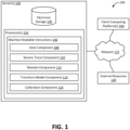
- FIG. 1 illustrates a system 100 configured for calibrating depth in a well to seismic data in a subsurface volume of interest, in accordance with one or more implementations.
- system 100 may include one or more servers 102.
- Server(s) 102 may be configured to communicate with one or more client computing platforms 104 according to a client/server architecture and/or other architectures.
- Client computing platform(s) 104 may be configured to communicate with other client computing platforms via server(s) 102 and/or according to a peer-to-peer architecture and/or other architectures. Users may access system 100 via client computing platform(s) 104.
- Server(s) 102 may be configured by machine-readable instructions 106.
- Machine-readable instructions 106 may include one or more instruction components.
- the instruction components may include computer program components.
- the instruction components may include one or more of a data component 108, a transform model component 110, a seismic trace component 112, a wavelet component 114, a calibration component 116, and/or other instruction components.
- Data component 108 may be configured to obtain well data corresponding to the well in the subsurface volume of interest.
- the well data specifies depth values of the well in the subsurface volume of interest.
- a subsurface volume of interest may include any area, region, and/or volume underneath a surface. Such a volume may include, or be bounded by, one or more of a water surface, a ground surface, and/or other surfaces.
- the well may be a production wellbore, injection wellbore, and/or other wellbore.
- FIG. 3A illustrates well data, in accordance with one or more implementations. As illustrated, original velocities are graphed along the x axis and corresponding depths are graphed on the y axis.
- data component 108 may be configured to convert the well data to converted well data.
- the converted well data specifies time values corresponding to the well data.
- Converting the well data to converted well data may include converting a top depth of the well to a corresponding time, t top .
- the time values may represent the subsurface energy travelling from a source to a given depth in the well in the subsurface volume of interest to a receiver device.
- checkshot velocities or seismic migration velocities may be used to determine t top .
- Checkshot velocities may be a measure of the travel from the surface to a known depth in a well by lowering seismic sources into the well.
- Seismic migration velocities may include migrating and/or shifting seismic traces to account for multiple, different offsets.
- FIG. 3B illustrates converted well data, in accordance with one or more implementations.
- well data may be converted into time values, graphed on the y axis and velocities are plotted on the x axis.
- seismic trace component 110 may be configured to obtain a seismic trace, corresponding to the well in the subsurface volume of interest, and a corresponding wavelet.
- the seismic trace specifies time values as a function of energy.
- the seismic trace may be subsurface data.
- the seismic trace may represent the subsurface energy travelling from a source to an interface in the subsurface volume of interest to a receiver device.
- Wavelet component 112 may be configured to apply the corresponding wavelet to the transformed well data to generate a modified signal. Applying the corresponding wavelet may include convolving the transformed well data. Convolution may, for example, involve convolving computed Zoeppritz reflection coefficients, as will be described herein, with the corresponding wavelet. The convolution may generate the modified signal. The modified signal may be a synthetic seismic or trace. It should be appreciated that wavelet component 112 may be used multiple times to apply multiple corresponding wavelets to multiple sets of transformed well data to generate multiple modified signals.
- FIG. 5 illustrates example transformed well data and an example modified signal, in accordance with one or more implementations.
- Applying the transform model to the converted well data generates transformed well data 502.
- Transformed well data 502 is used to generate modified signal 504.
- Modified signal 504 may be compared to a seismic trace (not shown). If, for example, modified signal 504 is the closest match, based on a correspondence, modified signal 504 and corresponding data may be selected to tie the well to the seismic trace.
- wavelet component 112 may be configured to generate the corresponding wavelet to a seismic trace.
- the corresponding wavelet is generated by using the seismic trace and a given reflectivity g m ⁇ R n , where R may represent the set of all real numbers and m may represent the modified signal.
- Reflectivity may be the ratio of amplitude of the reflected subsurface energy to the source subsurface energy wave, or how much subsurface energy is reflected off a subsurface interface. This reflectivity is based on the contrast in velocity and density across the subsurface interface.
- a Toeplitz circulant matrix may be generated: g m ⁇ R nxn .
- s ⁇ ⁇ may represent the corresponding wavelet
- F may represent a Fourier transform
- G ⁇ ⁇ may represent the modified matrix of the one or more reflectivities
- d ⁇ ⁇ may represent the seismic trace.
- the least squares estimate of the corresponding wavelet may be used with a singular value decomposition pseudoinverse that may discard singular values below 10 -8 .
- the resulting matrix may be used for the Fourier transformed least squares estimate to generate the corresponding wavelet. It should be appreciated that different methods may be used to achieve maximum energy values concentrated near a time (e.g., about 0).
- Transform model component 114 may be configured to generate a transform model based on one or more probabilities.
- the transform model includes a slope parameter and a shift parameter.
- the transform model may be based, in part, on an inversion, a Markov chain Monte Carlo sampling process, and/or other techniques.
- the transform model may include one or more parameters to stretch and/or squeeze data, shift the data, and/or otherwise modify the data.
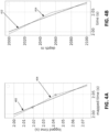
- FIG. 4A illustrates example model parameterizations, in accordance with one or more implementations. As illustrated, an original parameterization may be graphed as line 402. A transformed parameterization may be graphed as line 404 with three slopes, two pinch points and a bulk shift.
- FIG. 4B illustrates example transform models, in accordance with one or more implementations.
- Depth-time curve 412 corresponds to line 402 and depth-time curve 414 corresponds to line 404.
- Depth-time curve 404 may be the well-tying curve, if, for example, the modified signal is selected as a suitable match for the seismic trace.
- the transform model may include zero-phase low pass filtering interpolated log velocities at a frequency (e.g., about 100 Hz). It should be appreciated that different frequencies and/or other filtering techniques may be used for different applications.
- the transform model may include decimating filtered log velocities at a time (e.g., about 4 ms). It should be appreciated that different time values may be used to decimate the filtered log velocities for different applications.
- m represents an initial transform model
- m' represents the transform model
- p() represents a prior model probability for a given variable
- q() represents a proposal probability from a first variable to a second variable, represents a likelihood for a given transform model
- represents a determinant of a Jacobian of a transformation of variables while changing a number of slopes from the first transform model to the second transform model.
- a threshold probability value may be used to select a transform model from the multiple possible transform models.
- the transform model may need a fixed value for a symmetric perturbation of t top . For example, 5% of ⁇ t top may be used, based on a Gaussian proposal. It should be appreciated that other values may be used in different applications.
- p m ′ p m k + 1 ⁇ l 1 N ⁇ k p k + 1 p k and q m
- m ⁇ l N ⁇ k k + 1
- q m m ′ q m ′
- m ⁇ l N ⁇ k k + 1
- p m ′ p m ⁇ l k 1 N ⁇ k + 1 p k ⁇ 1 p k and q m
- the variables may use the same definitions as described above.
- d may represent the actual seismic trace
- t may represent a time value, such as, for example, converted well data
- C d may represent a covariance matrix between the noise in the data samples in the seismic trace. This may be a diagonal matrix, with diagonal entries providing an estimate of noise variance at corresponding time samples. Higher variance corresponds to lower signal to noise ratio.
- a Jacobian may be a matrix of first-order partial derivatives of a vector-valued function.
- the modification parameter includes one or more scalar values corresponding to one or more of an insertion of a given point between the one or more slopes in the converted well data, a deletion of the given point between the one or more slopes in the converted well data, a movement of the given point between the one or more slopes in the converted well data, a time shift of the converted well data, and/or other modifications to the converted well data.
- p(k) may equal 1 k .
- p(k) may equal 1 k .
- transform model component 114 may be configured to apply the transform model to the converted well data to transform the converted well data into transformed well data.
- the transformed well data specifies time values corresponding to the converted well data. It should be appreciated that transform model component 114 may be used multiple times to apply multiple transform models to the converted well data to transform the converted well data into multiple sets of transformed well data.
- Calibration component 116 may be configured to generate a correspondence between the modified signal and the seismic trace.
- the correspondence is a difference between the given modified signal and the seismic trace.
- the difference may be a mathematical difference between the modified signal and the seismic trace. It should be appreciated that calibration component 116 may be used multiple times to generate multiple correspondences between multiple modified signals and the seismic trace.
- calibration component 116 may be configured to select a given modified signal based on the correspondence between individual ones of the modified signals and the seismic trace.
- the given modified signal may be selected because the difference between the given modified signal and the seismic trace is the smallest compared to other modified signals. It should be appreciated that other factors may contribute to selecting the given modified signal, such as, for example, a highest probability based on the one or more probabilities, a corresponding likelihood, etc.
- calibration component 116 may be configured to calibrate the well data to the seismic trace based on a selected transformed well data corresponding to a selected modified signal.
- calibration component 116 may be configured to generate an uncertainty estimate for calibrating the well data to the seismic trace based on the multiple modified signals. Given that multiple transform models may be used to generate the multiple modified signals, uncertainty on the well ties may be generated based on the multiple, different properties corresponding to the multiple transform models.
- server(s) 102, client computing platform(s) 104, and/or external resources 128 may be operatively linked via one or more electronic communication links.
- electronic communication links may be established, at least in part, via a network 122 such as the Internet and/or other networks. It will be appreciated that this is not intended to be limiting, and that the scope of this disclosure includes implementations in which server(s) 102, client computing platform(s) 104, and/or external resources 128 may be operatively linked via some other communication media.
- a given client computing platform 104 may include one or more processors configured to execute computer program components.
- the computer program components may be configured to enable an expert or user associated with the given client computing platform 104 to interface with system 100 and/or external resources 128, and/or provide other functionality attributed herein to client computing platform(s) 104.
- the given client computing platform 104 may include one or more of a desktop computer, a laptop computer, a handheld computer, a tablet computing platform, a NetBook, a Smartphone, a gaming console, and/or other computing platforms.
- External resources 128 may include sources of information outside of system 100, external entities participating with system 100, and/or other resources. In some implementations, some or all of the functionality attributed herein to external resources 128 may be provided by resources included in system 100.
- Server(s) 102 may include electronic storage 130, one or more processors 132, and/or other components. Server(s) 102 may include communication lines, or ports to enable the exchange of information with a network and/or other computing platforms. Illustration of server(s) 102 in FIG. 1 is not intended to be limiting. Server(s) 102 may include a plurality of hardware, software, and/or firmware components operating together to provide the functionality attributed herein to server(s) 102. For example, server(s) 102 may be implemented by a cloud of computing platforms operating together as server(s) 102.
- Electronic storage 130 may include non-transitory storage media that electronically stores information.
- the electronic storage media of electronic storage 130 may include one or both of system storage that is provided integrally (i.e., substantially non-removable) with server(s) 102 and/or removable storage that is removably connectable to server(s) 102 via, for example, a port (e.g., a USB port, a firewire port, etc.) or a drive (e.g., a disk drive, etc.).
- a port e.g., a USB port, a firewire port, etc.
- a drive e.g., a disk drive, etc.
- Electronic storage 130 may include one or more of optically readable storage media (e.g., optical disks, etc.), magnetically readable storage media (e.g., magnetic tape, magnetic hard drive, floppy drive, etc.), electrical charge-based storage media (e.g., EEPROM, RAM, etc.), solid-state storage media (e.g., flash drive, etc.), non-transient electronic storage, and/or other electronically readable storage media.
- Electronic storage 130 may include one or more virtual storage resources (e.g., cloud storage, a virtual private network, and/or other virtual storage resources).
- Electronic storage 130 may store software algorithms, information determined by processor(s) 132, information received from server(s) 102, information received from client computing platform(s) 104, and/or other information that enables server(s) 102 to function as described herein.
- Processor(s) 132 may be configured to provide information processing capabilities in server(s) 102.
- processor(s) 132 may include one or more of a physical computer processor, a digital processor, an analog processor, a digital circuit designed to process information, an analog circuit designed to process information, a state machine, and/or other mechanisms for electronically processing information.
- processor(s) 132 is shown in FIG. 1 as a single entity, this is for illustrative purposes only.
- processor(s) 132 may include a plurality of processing units. These processing units may be physically located within the same device, or processor(s) 132 may represent processing functionality of a plurality of devices operating in coordination.
- Processor(s) 132 may be configured to execute components 108, 110, 112, 114, and/or 116, and/or other components.
- Processor(s) 132 may be configured to execute components 108, 110, 112, 114, and/or 116, and/or other components by software; hardware; firmware; some combination of software, hardware, and/or firmware; and/or other mechanisms for configuring processing capabilities on processor(s) 132.
- the term "component” may refer to any component or set of components that perform the functionality attributed to the component. This may include one or more physical processors during execution of processor readable instructions, the processor readable instructions, circuitry, hardware, storage media, or any other components.
- components 108, 110, 112, 114, and/or 116 are illustrated in FIG. 1 as being implemented within a single processing unit, in implementations in which processor(s) 132 includes multiple processing units, one or more of components 108, 110, 112, 114, and/or 116 may be implemented remotely from the other components.
- the description of the functionality provided by the different components 108, 110, 112, 114, and/or 116 described below is for illustrative purposes, and is not intended to be limiting, as any of components 108, 110, 112, 114, and/or 116 may provide more or less functionality than is described.
- processor(s) 132 may be configured to execute one or more additional components that may perform some or all of the functionality attributed below to one of components 108, 110, 112, 114, and/or 116.
- FIG. 2 illustrates a method 200 for calibrating depth in a well to seismic data in a subsurface volume of interest, in accordance with one or more implementations.
- the operations of method 200 presented below are intended to be illustrative. In some implementations, method 200 may be accomplished with one or more additional operations not described, and/or without one or more of the operations discussed. Additionally, the order in which the operations of method 200 are illustrated in FIG. 2 and described below is not intended to be limiting.
- Method 200 is implemented in one or more processing devices (e.g., a physical computer processor, a digital processor, an analog processor, a digital circuit designed to process information, an analog circuit designed to process information, a state machine, and/or other mechanisms for electronically processing information).
- the one or more processing devices may include one or more devices executing some or all of the operations of method 200 in response to instructions stored electronically on an electronic storage medium, such as, for example, non-transient electronic storage .
- the one or more processing devices may include one or more devices configured through hardware, firmware, and/or software to be specifically designed for execution of one or more of the operations of method 200.
- An operation 202 includes obtaining well data corresponding to the well in the subsurface volume of interest.
- the well data specifies depth values of the well in the subsurface volume of interest.
- Operation 202 may be performed by one or more processors configured by machine-readable instructions including a component that is the same as or similar to data component 108, in accordance with one or more implementations.
- An operation 204 includes converting the well data to converted well data.
- Operation 204 may be performed by one or more processors configured by machine-readable instructions including a component that is the same as or similar to data component 108, in accordance with one or more implementations.
- An operation 206 includes obtaining a seismic trace, corresponding to the well in the subsurface volume of interest, and a corresponding wavelet.
- the seismic trace specifies time values as a function of energy.
- the corresponding wavelet is generated by using the seismic trace.
- Operation 206 may be performed by one or more processors configured by machine-readable instructions including a component that is the same as or similar to seismic trace component 110, in accordance with one or more implementations.
- An operation 208 includes generating a transform model based on one or more probabilities.
- the transform model includes a slope parameter and a shift parameter.
- the modification parameter, ⁇ has one or more scalar values corresponding to one or more of an insertion of a slope in the converted well data, a deletion of the slope in the converted well data, a movement of the slope in the converted well data, a time shift of the converted well data, and/or other modifications.
- Example equations for the modification parameter, ⁇ are described in greater detail above. Operation 208 may be performed by one or more processors configured by machine-readable instructions including a component that is the same as or similar to transform model component 114, in accordance with one or more implementations.
- An operation 210 includes applying the transform model to the converted well data to transform the converted well data into transformed well data.
- the transformed well data specifies time values corresponding to the converted well data.
- Example transform models may be described in greater detail above. Operation 210 may be performed by one or more processors configured by machine-readable instructions including a component that is the same as or similar to data component 108, in accordance with one or more implementations.
- An operation 212 includes applying the corresponding wavelet to the transformed well data to generate a modified signal. Operation 212 may be performed by one or more processors configured by machine-readable instructions including a component that is the same as or similar to wavelet component 112, in accordance with one or more implementations.
- An operation 214 includes generating a correspondence between the modified signal and the seismic trace.
- the correspondence is a difference between the given modified signal and the seismic trace.
- Operation 214 may be performed by one or more processors configured by machine-readable instructions including a component that is the same as or similar to calibration component 116, in accordance with one or more implementations.
- An operation 216 includes repeating 208-214 to select a given modified signal, based on the correspondence between individual ones of the modified signals and the seismic trace. Operation 216 may be performed by one or more processors configured by machine-readable instructions including a component that is the same as or similar to calibration component 116, in accordance with one or more implementations.
- An operation 218 may include calibrating the well data to the seismic trace based on a selected transformed well data corresponding to a selected modified signal.
- the calibration may include an uncertainty estimate based on the multiple modified signals.
- Operation 218 may be performed by one or more processors configured by machine-readable instructions including a component that is the same as or similar to calibration component 116, in accordance with one or more implementations.
Landscapes
- Physics & Mathematics (AREA)
- Life Sciences & Earth Sciences (AREA)
- Engineering & Computer Science (AREA)
- Remote Sensing (AREA)
- General Life Sciences & Earth Sciences (AREA)
- General Physics & Mathematics (AREA)
- Geophysics (AREA)
- Acoustics & Sound (AREA)
- Environmental & Geological Engineering (AREA)
- Geology (AREA)
- Manufacturing & Machinery (AREA)
- Geophysics And Detection Of Objects (AREA)
Claims (13)
- Computerimplementiertes Verfahren (200) zum Kalibrieren der Tiefe in einem Bohrloch auf erfasste seismische Daten in einem unterirdischen Volumen von Interesse, wobei das Verfahren (200) in einem Computersystem implementiert wird, das einen oder mehrere physische Computerprozessoren und nichtflüchtigen elektronischen Speicher beinhaltet, umfassend:a) Erhalten (202), aus dem nichtflüchtigen elektronischen Speicher, von Bohrlochdaten, die dem Bohrloch im unterirdischen Volumen von Interesse entsprechen, wobei die Bohrlochdaten protokollierte Bohrtiefen umfassen, die Tiefenwerte des Bohrlochs in dem unterirdischen Volumen von Interesse angeben;b) Umwandeln (204), mit dem einen oder den mehreren physischen Computerprozessoren, der Bohrlochdaten in umgewandelte Bohrlochdaten, wobei die umgewandelten Bohrlochdaten Zeitwerte angeben, die den Bohrlochdaten entsprechen;c) Erhalten (206), aus dem nichtflüchtigen elektronischen Speicher, einer seismischen Spur, die dem Bohrloch in dem unterirdischen Volumen von Interesse entspricht, und eines entsprechenden Wavelets, wobei die seismische Spur Zeitwerte als Funktion der Energie angibt, wobei das Erhalten des entsprechenden Wavelets Erzeugen des entsprechenden Wavelets unter Verwendung der seismischen Spur und der Reflektivität basierend auf dem Kontrast der Geschwindigkeit und Dichte über eine unterirdische Grenzfläche hinweg umfasst, wobei die Reflektivität angibt, wie viel unterirdische Energie von der unterirdischen Grenzfläche reflektiert wird;d) Erzeugen (208), mit dem einen oder den mehreren physischen Computerprozessoren, eines Transformationsmodells basierend auf einer oder mehreren Wahrscheinlichkeiten und einem Modifikationsparameter mit Skalarwerten, die einem Einfügen einer Steigung in die umgewandelten Bohrlochdaten und/oder einem Löschen der Steigung in den umgewandelten Bohrlochdaten und/oder einer Bewegung der Steigung in den umgewandelten Bohrlochdaten und/oder einer Zeitverschiebung der umgewandelten Bohrlochdaten entsprechen, wobei das Transformationsmodell einen Steigungsparameter und einen Verschiebungsparameter beinhaltet;e) Anwenden (210), mit dem einen oder den mehreren physischen Computerprozessoren, des Transformationsmodells auf die umgewandelten Bohrlochdaten, um die umgewandelten Bohrlochdaten in transformierte Bohrlochdaten umzuwandeln, wobei die transformierten Bohrlochdaten Zeitwerte angeben, die den umgewandelten Bohrlochdaten entsprechen;f) Anwenden (212), mit dem einen oder den mehreren physischen Computerprozessoren, des entsprechenden Wavelets auf die umgewandelten Bohrlochdaten, um ein modifiziertes Signal zu erzeugen;g) Erzeugen (214), mit dem einen oder den mehreren physischen Computerprozessoren, einer Entsprechung zwischen dem modifizierten Signal und der seismischen Spur, wobei die Entsprechung eine Differenz zwischen dem modifizierten Signal und der seismischen Spur ist; undh) Wiederholen (216), mit dem einen oder den mehreren physischen Computerprozessoren, der Schritte d) - g), um ein gegebenes modifiziertes Signal und die entsprechenden transformierten Bohrlochdaten auszuwählen, um das Bohrloch an die seismische Spur zu binden, basierend auf der Entsprechung zwischen einzelnen der modifizierten Signale und der seismischen Spur,wobei eine der einen oder der mehreren Wahrscheinlichkeiten, die zum Erzeugen eines zweiten Transformationsmodells, m', verwendet werden, auf einer Wahrscheinlichkeit α basiert:
 wobei m für ein erstes Transformationsmodell steht, β für den Modifikationsparameter steht und L für eine Wahrscheinlichkeit für ein gegebenes Transformationsmodell steht.
 - Computerimplementiertes Verfahren (200) nach Anspruch 1, ferner umfassend:
Kalibrieren (218), mit dem einen oder den mehreren physischen Computerprozessoren, der Bohrlochdaten auf die seismische Spur basierend auf einem ausgewählten Satz transformierter Bohrlochdaten, die einem ausgewählten modifizierten Signal entsprechen. - Computerimplementiertes Verfahren (200) nach Anspruch 2, ferner umfassend:
Erzeugen, mit dem einen oder den mehreren physischen Computerprozessoren, einer Unsicherheitsschätzung für das Kalibrieren der Bohrlochdaten auf die seismische Spur basierend auf den mehreren modifizierten Signalen. - Computerimplementiertes Verfahren (200) nach Anspruch 1, wobei das entsprechende Wavelet,


- Computerimplementiertes Verfahren (200) nach Anspruch 1, wobei eine der einen oder der mehreren Wahrscheinlichkeiten, die zum Erzeugen eines zweiten Transformationsmodells, m', verwendet werden, auf einer Wahrscheinlichkeit α basiert:

- Computerimplementiertes Verfahren (200) nach Anspruch 1, wobei der Modifikationsparameter, β, für das Einfügen eines Punkts zwischen Steigungen wie folgt ist:

- Computerimplementiertes Verfahren (200) nach Anspruch 1, wobei der Modifikationsparameter, β, für das Löschen eines Punkts zwischen Steigungen wie folgt ist:

- Computerimplementiertes Verfahren (200) nach Anspruch 1, wobei der Modifikationsparameter, β, für die Bewegung eines Punkts zwischen Steigungen oder eine Zeitverschiebung der Bohrlochdaten mit der Zeit gleich 1 ist.
- Computerimplementiertes Verfahren (200) nach Anspruch 1, wobei eine der einen oder der mehreren Wahrscheinlichkeiten, die zur Erzeugung eines gegebenen Transformationsmodells, m, verwendet werden, wie folgt ist:

- Computerimplementiertes Verfahren (200) nach Anspruch 1, wobei das Umwandeln der mehreren Tiefenwerte der Bohrlochdaten in Zeitwerte Folgendes umfasst:Umwandeln einer obersten Tiefe des Bohrlochs in eine entsprechende Zeit, ttop ; undErzeugen der umgewandelten Bohrlochdaten unter Verwendung von
 wobei tn ein gegebener Zeitwert der umgewandelten Bohrlochdaten ist, Nt für eine Gesamtzahl von Zeitwerten steht, z für einen Tiefenwert steht und v für einen Geschwindigkeitswert steht.
 - System (100) zum Kalibrieren der Tiefe in einem Bohrloch auf seismische Daten in einem unterirdischen Volumen von Interesse, wobei das System (100) Folgendes umfasst:einen nichtflüchtigen elektronischen Speicher (130); undeinen oder mehrere physische Computerprozessoren (132), die durch maschinenlesbare Anweisungen zum Ausführen des Verfahrens nach einem der vorhergehenden Ansprüche konfiguriert werden.
- Computerprogramm oder mehrere Computerprogramme, die Anweisungen umfassen, die bei Ausführung durch einen Computer bewirken, dass der Computer das Verfahren nach einem der Ansprüche 1 bis 10 ausführt.
- Computerlesbares Speichermedium, auf dem das eine oder die mehreren Computerprogramme nach Anspruch 12 gespeichert sind.
Applications Claiming Priority (2)
| Application Number | Priority Date | Filing Date | Title |
|---|---|---|---|
| US16/227,944 US11275193B2 (en) | 2018-12-20 | 2018-12-20 | Methods and systems for calibrating depth in a well to seismic data in a subsurface volume of interest |
| PCT/US2019/064921 WO2020131424A1 (en) | 2018-12-20 | 2019-12-06 | Methods and systems for calibrating depth in a well to seismic data in a subsurface volume of interest |
Publications (3)
| Publication Number | Publication Date |
|---|---|
| EP3899592A1 EP3899592A1 (de) | 2021-10-27 |
| EP3899592A4 EP3899592A4 (de) | 2022-08-17 |
| EP3899592B1 true EP3899592B1 (de) | 2024-11-20 |
Family
ID=71099327
Family Applications (1)
| Application Number | Title | Priority Date | Filing Date |
|---|---|---|---|
| EP19899826.2A Active EP3899592B1 (de) | 2018-12-20 | 2019-12-06 | Verfahren und system zur kalibrierung der tiefe in einem bohrloch mit seismischen daten in einem interessierenden unterirdischen volumen |
Country Status (4)
| Country | Link |
|---|---|
| US (1) | US11275193B2 (de) |
| EP (1) | EP3899592B1 (de) |
| AU (1) | AU2019406345B2 (de) |
| WO (1) | WO2020131424A1 (de) |
Families Citing this family (7)
| Publication number | Priority date | Publication date | Assignee | Title |
|---|---|---|---|---|
| US12092783B2 (en) | 2020-09-22 | 2024-09-17 | Chevron U.S.A. Inc. | Systems and methods for generating subsurface property data as a function of position and time in a subsurface volume of interest |
| US12481079B2 (en) | 2020-09-22 | 2025-11-25 | Chevron U.S.A. Inc. | Systems and methods for generating elastic property data as a function of position and time in a subsurface volume of interest |
| US11733414B2 (en) * | 2020-09-22 | 2023-08-22 | Chevron U.S.A. Inc. | Systems and methods for generating subsurface data as a function of position and time in a subsurface volume of interest |
| CN114355451B (zh) * | 2022-01-07 | 2024-08-20 | 西南石油大学 | 一种基于多道地震叠加的井震标定方法 |
| CN114545523B (zh) * | 2022-02-25 | 2023-03-24 | 成都理工大学 | 一种深度域测井和地震数据的直接标定方法 |
| CN116719099B (zh) * | 2023-06-12 | 2025-12-05 | 西南石油大学 | 一种基于分步匹配寻优的井震精确标定方法 |
| CN119556338B (zh) * | 2024-11-27 | 2026-02-24 | 成都理工大学 | 一种瞬态匹配挤压变换储层边界刻画方法 |
Family Cites Families (12)
| Publication number | Priority date | Publication date | Assignee | Title |
|---|---|---|---|---|
| US5691958A (en) | 1995-04-13 | 1997-11-25 | Exxon Production Research Company | Method for determining formation properties from seismic attributes |
| US7082367B2 (en) | 2004-07-02 | 2006-07-25 | Veritas Dgc Inc. | Seismic data calibration using crossplotted AVO attributes |
| US9223041B2 (en) * | 2008-01-23 | 2015-12-29 | Schlubmerger Technology Corporation | Three-dimensional mechanical earth modeling |
| WO2009142872A1 (en) | 2008-05-22 | 2009-11-26 | Exxonmobil Upstream Research Company | Seismic horizon skeletonization |
| US8649980B2 (en) | 2010-03-05 | 2014-02-11 | Vialogy Llc | Active noise injection computations for improved predictability in oil and gas reservoir characterization and microseismic event analysis |
| US9945970B1 (en) | 2011-08-29 | 2018-04-17 | Seismic Innovations | Method and apparatus for modeling microseismic event location estimate accuracy |
| US10977396B2 (en) * | 2012-01-13 | 2021-04-13 | Schlumberger Technology Corporation | Determining an elastic model for a geologic region |
| GB2505042B (en) * | 2012-06-13 | 2014-10-08 | Schlumberger Holdings | Seismic trace attribute |
| CN105445802A (zh) | 2014-09-04 | 2016-03-30 | 中国石油化工股份有限公司 | 一种基于时频谱约束的高精度时深校正方法 |
| US20170248716A1 (en) | 2014-11-14 | 2017-08-31 | Cgg Services Sas | Device and method for weighted sparse inversion for seismic processing |
| US10295683B2 (en) * | 2016-01-05 | 2019-05-21 | Schlumberger Technology Corporation | Amplitude inversion on partitioned depth image gathers using point spread functions |
| CN108562938B (zh) | 2018-03-23 | 2019-09-06 | 中国石油天然气股份有限公司 | 一种消除频散效应的方法、装置及系统 |
-
2018
- 2018-12-20 US US16/227,944 patent/US11275193B2/en active Active
-
2019
- 2019-12-06 AU AU2019406345A patent/AU2019406345B2/en active Active
- 2019-12-06 WO PCT/US2019/064921 patent/WO2020131424A1/en not_active Ceased
- 2019-12-06 EP EP19899826.2A patent/EP3899592B1/de active Active
Also Published As
| Publication number | Publication date |
|---|---|
| EP3899592A4 (de) | 2022-08-17 |
| US11275193B2 (en) | 2022-03-15 |
| EP3899592A1 (de) | 2021-10-27 |
| US20200200935A1 (en) | 2020-06-25 |
| WO2020131424A1 (en) | 2020-06-25 |
| AU2019406345A1 (en) | 2021-06-17 |
| AU2019406345B2 (en) | 2022-09-29 |
Similar Documents
| Publication | Publication Date | Title |
|---|---|---|
| US11275193B2 (en) | Methods and systems for calibrating depth in a well to seismic data in a subsurface volume of interest | |
| CN103703391B (zh) | 使用频谱整形的全波场反演的系统和计算机实施的方法 | |
| Gholami | A fast automatic multichannel blind seismic inversion for high-resolution impedance recovery | |
| Sen et al. | Transdimensional seismic inversion using the reversible jump Hamiltonian Monte Carlo algorithm | |
| Gholami | Nonlinear multichannel impedance inversion by total-variation regularization | |
| Esser et al. | Constrained waveform inversion for automatic salt flooding | |
| JP7019713B2 (ja) | 共通焦点法を用いる連続的な地震貯留層モニタリング | |
| EP3776270B1 (de) | Systeme und verfahren zur verwendung von wahrscheinlichkeiten von lithologien bei einer inversion | |
| WO2012170090A1 (en) | System and method for data inversion with phase unwrapping | |
| EP2718744A1 (de) | System und verfahren zur umkehrung seismischer daten | |
| EP4446782A2 (de) | Systeme und verfahren zur verfeinerung von geschätzten parameterwerten in der seismischen bildgebung | |
| EP3211594B1 (de) | System zur seismischen modellierung mit bereitstellung retuschierter seismischer vermessungsdaten auf basis von vergleichen der grenzen verdächtiger regionen sowie zugehörige verfahren | |
| Herrmann et al. | Frugal full-waveform inversion: From theory to a practical algorithm | |
| Lundsgaard et al. | Joint Bayesian wavelet and well-path estimation in the impedance domain | |
| Chen et al. | Unsupervised seismic acoustic impedance inversion based on generative diffusion model | |
| EP3217354B1 (de) | System zur seismischen modellierung mit bereitstellung von frequenzbereichszerlegung von seismischen vermessungsdaten und zugehörige verfahren | |
| CN106547021B (zh) | 基于单井褶积算法建立初始模型的方法和装置 | |
| EP2496968B1 (de) | System und verfahren zur seismischen strahlformung unter berücksichtigung von gerätefehlausrichtungen | |
| CN119716979B (zh) | 基于物理模型约束的地震波阻抗高分辨率反演方法、装置、设备及存储介质 | |
| CN106199714B (zh) | 地震数据等效主频计算的方法和装置 | |
| Wang et al. | Bayesian reverse time migration with quantified uncertainty | |
| Hu et al. | Accelerating seismic inversion and uncertainty quantification with efficient high-rank Hessian approximations | |
| Alfayez et al. | Diffusion model priors in ensemble smoother seismic inversion | |
| Class et al. | Patent application title: Convergence Rate of Full Wavefield Inversion Using Spectral Shaping Inventors: Partha S. Routh (Katy, TX, US) Partha S. Routh (Katy, TX, US) Spyridon K. Lazaratos (Houston, TX, US) Anatoly Baumstein (Houston, TX, US) Anatoly Baumstein (Houston, TX, US) Ivan Chikichev (Houston, TX, US) Ke Wang (Sugar Land, TX, US) Ke Wang (Sugar Land, TX, US) | |
| Ustad et al. | Creating Singularity Order Attribute of Seismic Signals Using Continuous Wavelet Transform (CWT) for Stratigraphic Interpretation Tools |
Legal Events
| Date | Code | Title | Description |
|---|---|---|---|
| STAA | Information on the status of an ep patent application or granted ep patent |
Free format text: STATUS: THE INTERNATIONAL PUBLICATION HAS BEEN MADE |
|
| PUAI | Public reference made under article 153(3) epc to a published international application that has entered the european phase |
Free format text: ORIGINAL CODE: 0009012 |
|
| STAA | Information on the status of an ep patent application or granted ep patent |
Free format text: STATUS: REQUEST FOR EXAMINATION WAS MADE |
|
| 17P | Request for examination filed |
Effective date: 20210527 |
|
| AK | Designated contracting states |
Kind code of ref document: A1 Designated state(s): AL AT BE BG CH CY CZ DE DK EE ES FI FR GB GR HR HU IE IS IT LI LT LU LV MC MK MT NL NO PL PT RO RS SE SI SK SM TR |
|
| DAV | Request for validation of the european patent (deleted) | ||
| DAX | Request for extension of the european patent (deleted) | ||
| A4 | Supplementary search report drawn up and despatched |
Effective date: 20220719 |
|
| RIC1 | Information provided on ipc code assigned before grant |
Ipc: G01V 1/48 20060101ALI20220713BHEP Ipc: G01V 1/28 20060101ALI20220713BHEP Ipc: G01V 1/30 20060101AFI20220713BHEP |
|
| P01 | Opt-out of the competence of the unified patent court (upc) registered |
Effective date: 20230522 |
|
| STAA | Information on the status of an ep patent application or granted ep patent |
Free format text: STATUS: EXAMINATION IS IN PROGRESS |
|
| 17Q | First examination report despatched |
Effective date: 20240214 |
|
| GRAP | Despatch of communication of intention to grant a patent |
Free format text: ORIGINAL CODE: EPIDOSNIGR1 |
|
| STAA | Information on the status of an ep patent application or granted ep patent |
Free format text: STATUS: GRANT OF PATENT IS INTENDED |
|
| INTG | Intention to grant announced |
Effective date: 20240709 |
|
| RAP3 | Party data changed (applicant data changed or rights of an application transferred) |
Owner name: CHEVRON U.S.A. INC. |
|
| GRAS | Grant fee paid |
Free format text: ORIGINAL CODE: EPIDOSNIGR3 |
|
| GRAA | (expected) grant |
Free format text: ORIGINAL CODE: 0009210 |
|
| STAA | Information on the status of an ep patent application or granted ep patent |
Free format text: STATUS: THE PATENT HAS BEEN GRANTED |
|
| AK | Designated contracting states |
Kind code of ref document: B1 Designated state(s): AL AT BE BG CH CY CZ DE DK EE ES FI FR GB GR HR HU IE IS IT LI LT LU LV MC MK MT NL NO PL PT RO RS SE SI SK SM TR |
|
| REG | Reference to a national code |
Ref country code: GB Ref legal event code: FG4D |
|
| REG | Reference to a national code |
Ref country code: CH Ref legal event code: EP |
|
| REG | Reference to a national code |
Ref country code: DE Ref legal event code: R096 Ref document number: 602019062405 Country of ref document: DE |
|
| REG | Reference to a national code |
Ref country code: IE Ref legal event code: FG4D |
|
| REG | Reference to a national code |
Ref country code: NL Ref legal event code: FP |
|
| REG | Reference to a national code |
Ref country code: LT Ref legal event code: MG9D |
|
| PG25 | Lapsed in a contracting state [announced via postgrant information from national office to epo] |
Ref country code: PT Free format text: LAPSE BECAUSE OF FAILURE TO SUBMIT A TRANSLATION OF THE DESCRIPTION OR TO PAY THE FEE WITHIN THE PRESCRIBED TIME-LIMIT Effective date: 20250320 Ref country code: HR Free format text: LAPSE BECAUSE OF FAILURE TO SUBMIT A TRANSLATION OF THE DESCRIPTION OR TO PAY THE FEE WITHIN THE PRESCRIBED TIME-LIMIT Effective date: 20241120 Ref country code: IS Free format text: LAPSE BECAUSE OF FAILURE TO SUBMIT A TRANSLATION OF THE DESCRIPTION OR TO PAY THE FEE WITHIN THE PRESCRIBED TIME-LIMIT Effective date: 20250320 |
|
| PG25 | Lapsed in a contracting state [announced via postgrant information from national office to epo] |
Ref country code: FI Free format text: LAPSE BECAUSE OF FAILURE TO SUBMIT A TRANSLATION OF THE DESCRIPTION OR TO PAY THE FEE WITHIN THE PRESCRIBED TIME-LIMIT Effective date: 20241120 |
|
| REG | Reference to a national code |
Ref country code: AT Ref legal event code: MK05 Ref document number: 1744068 Country of ref document: AT Kind code of ref document: T Effective date: 20241120 |
|
| PG25 | Lapsed in a contracting state [announced via postgrant information from national office to epo] |
Ref country code: BG Free format text: LAPSE BECAUSE OF FAILURE TO SUBMIT A TRANSLATION OF THE DESCRIPTION OR TO PAY THE FEE WITHIN THE PRESCRIBED TIME-LIMIT Effective date: 20241120 |
|
| PG25 | Lapsed in a contracting state [announced via postgrant information from national office to epo] |
Ref country code: ES Free format text: LAPSE BECAUSE OF FAILURE TO SUBMIT A TRANSLATION OF THE DESCRIPTION OR TO PAY THE FEE WITHIN THE PRESCRIBED TIME-LIMIT Effective date: 20241120 |
|
| PG25 | Lapsed in a contracting state [announced via postgrant information from national office to epo] |
Ref country code: GR Free format text: LAPSE BECAUSE OF FAILURE TO SUBMIT A TRANSLATION OF THE DESCRIPTION OR TO PAY THE FEE WITHIN THE PRESCRIBED TIME-LIMIT Effective date: 20250221 Ref country code: AT Free format text: LAPSE BECAUSE OF FAILURE TO SUBMIT A TRANSLATION OF THE DESCRIPTION OR TO PAY THE FEE WITHIN THE PRESCRIBED TIME-LIMIT Effective date: 20241120 Ref country code: LV Free format text: LAPSE BECAUSE OF FAILURE TO SUBMIT A TRANSLATION OF THE DESCRIPTION OR TO PAY THE FEE WITHIN THE PRESCRIBED TIME-LIMIT Effective date: 20241120 |
|
| PG25 | Lapsed in a contracting state [announced via postgrant information from national office to epo] |
Ref country code: PL Free format text: LAPSE BECAUSE OF FAILURE TO SUBMIT A TRANSLATION OF THE DESCRIPTION OR TO PAY THE FEE WITHIN THE PRESCRIBED TIME-LIMIT Effective date: 20241120 |
|
| PG25 | Lapsed in a contracting state [announced via postgrant information from national office to epo] |
Ref country code: RS Free format text: LAPSE BECAUSE OF FAILURE TO SUBMIT A TRANSLATION OF THE DESCRIPTION OR TO PAY THE FEE WITHIN THE PRESCRIBED TIME-LIMIT Effective date: 20250220 |
|
| REG | Reference to a national code |
Ref country code: DE Ref legal event code: R119 Ref document number: 602019062405 Country of ref document: DE |
|
| PG25 | Lapsed in a contracting state [announced via postgrant information from national office to epo] |
Ref country code: SM Free format text: LAPSE BECAUSE OF FAILURE TO SUBMIT A TRANSLATION OF THE DESCRIPTION OR TO PAY THE FEE WITHIN THE PRESCRIBED TIME-LIMIT Effective date: 20241120 |
|
| PG25 | Lapsed in a contracting state [announced via postgrant information from national office to epo] |
Ref country code: DK Free format text: LAPSE BECAUSE OF FAILURE TO SUBMIT A TRANSLATION OF THE DESCRIPTION OR TO PAY THE FEE WITHIN THE PRESCRIBED TIME-LIMIT Effective date: 20241120 |
|
| PG25 | Lapsed in a contracting state [announced via postgrant information from national office to epo] |
Ref country code: EE Free format text: LAPSE BECAUSE OF FAILURE TO SUBMIT A TRANSLATION OF THE DESCRIPTION OR TO PAY THE FEE WITHIN THE PRESCRIBED TIME-LIMIT Effective date: 20241120 |
|
| PG25 | Lapsed in a contracting state [announced via postgrant information from national office to epo] |
Ref country code: RO Free format text: LAPSE BECAUSE OF FAILURE TO SUBMIT A TRANSLATION OF THE DESCRIPTION OR TO PAY THE FEE WITHIN THE PRESCRIBED TIME-LIMIT Effective date: 20241120 |
|
| PG25 | Lapsed in a contracting state [announced via postgrant information from national office to epo] |
Ref country code: SK Free format text: LAPSE BECAUSE OF FAILURE TO SUBMIT A TRANSLATION OF THE DESCRIPTION OR TO PAY THE FEE WITHIN THE PRESCRIBED TIME-LIMIT Effective date: 20241120 |
|
| PG25 | Lapsed in a contracting state [announced via postgrant information from national office to epo] |
Ref country code: CZ Free format text: LAPSE BECAUSE OF FAILURE TO SUBMIT A TRANSLATION OF THE DESCRIPTION OR TO PAY THE FEE WITHIN THE PRESCRIBED TIME-LIMIT Effective date: 20241120 |
|
| PG25 | Lapsed in a contracting state [announced via postgrant information from national office to epo] |
Ref country code: IT Free format text: LAPSE BECAUSE OF FAILURE TO SUBMIT A TRANSLATION OF THE DESCRIPTION OR TO PAY THE FEE WITHIN THE PRESCRIBED TIME-LIMIT Effective date: 20241120 |
|
| REG | Reference to a national code |
Ref country code: CH Ref legal event code: PL |
|
| PG25 | Lapsed in a contracting state [announced via postgrant information from national office to epo] |
Ref country code: LU Free format text: LAPSE BECAUSE OF NON-PAYMENT OF DUE FEES Effective date: 20241206 |
|
| PG25 | Lapsed in a contracting state [announced via postgrant information from national office to epo] |
Ref country code: SE Free format text: LAPSE BECAUSE OF FAILURE TO SUBMIT A TRANSLATION OF THE DESCRIPTION OR TO PAY THE FEE WITHIN THE PRESCRIBED TIME-LIMIT Effective date: 20241120 |
|
| PG25 | Lapsed in a contracting state [announced via postgrant information from national office to epo] |
Ref country code: MC Free format text: LAPSE BECAUSE OF FAILURE TO SUBMIT A TRANSLATION OF THE DESCRIPTION OR TO PAY THE FEE WITHIN THE PRESCRIBED TIME-LIMIT Effective date: 20241120 |
|
| PLBE | No opposition filed within time limit |
Free format text: ORIGINAL CODE: 0009261 |
|
| STAA | Information on the status of an ep patent application or granted ep patent |
Free format text: STATUS: NO OPPOSITION FILED WITHIN TIME LIMIT |
|
| REG | Reference to a national code |
Ref country code: BE Ref legal event code: MM Effective date: 20241231 |
|
| PG25 | Lapsed in a contracting state [announced via postgrant information from national office to epo] |
Ref country code: DE Free format text: LAPSE BECAUSE OF NON-PAYMENT OF DUE FEES Effective date: 20250701 |
|
| PG25 | Lapsed in a contracting state [announced via postgrant information from national office to epo] |
Ref country code: BE Free format text: LAPSE BECAUSE OF NON-PAYMENT OF DUE FEES Effective date: 20241231 |
|
| PG25 | Lapsed in a contracting state [announced via postgrant information from national office to epo] |
Ref country code: CH Free format text: LAPSE BECAUSE OF NON-PAYMENT OF DUE FEES Effective date: 20241231 |
|
| 26N | No opposition filed |
Effective date: 20250821 |
|
| PG25 | Lapsed in a contracting state [announced via postgrant information from national office to epo] |
Ref country code: IE Free format text: LAPSE BECAUSE OF NON-PAYMENT OF DUE FEES Effective date: 20241206 |
|
| PGFP | Annual fee paid to national office [announced via postgrant information from national office to epo] |
Ref country code: NL Payment date: 20251112 Year of fee payment: 7 |
|
| PGFP | Annual fee paid to national office [announced via postgrant information from national office to epo] |
Ref country code: GB Payment date: 20251030 Year of fee payment: 7 |
|
| PGFP | Annual fee paid to national office [announced via postgrant information from national office to epo] |
Ref country code: NO Payment date: 20251210 Year of fee payment: 7 |
|
| PGFP | Annual fee paid to national office [announced via postgrant information from national office to epo] |
Ref country code: FR Payment date: 20251110 Year of fee payment: 7 |
|
| PG25 | Lapsed in a contracting state [announced via postgrant information from national office to epo] |
Ref country code: CY Free format text: LAPSE BECAUSE OF FAILURE TO SUBMIT A TRANSLATION OF THE DESCRIPTION OR TO PAY THE FEE WITHIN THE PRESCRIBED TIME-LIMIT; INVALID AB INITIO Effective date: 20191206 |