EP3899592B1 - Method and system for calibrating depth in a well to seismic data in a subsurface volume of interest - Google Patents
Method and system for calibrating depth in a well to seismic data in a subsurface volume of interest Download PDFInfo
- Publication number
- EP3899592B1 EP3899592B1 EP19899826.2A EP19899826A EP3899592B1 EP 3899592 B1 EP3899592 B1 EP 3899592B1 EP 19899826 A EP19899826 A EP 19899826A EP 3899592 B1 EP3899592 B1 EP 3899592B1
- Authority
- EP
- European Patent Office
- Prior art keywords
- well data
- well
- data
- converted
- computer
- Prior art date
- Legal status (The legal status is an assumption and is not a legal conclusion. Google has not performed a legal analysis and makes no representation as to the accuracy of the status listed.)
- Active
Links
Images



Classifications
-
- G—PHYSICS
- G01—MEASURING; TESTING
- G01V—GEOPHYSICS; GRAVITATIONAL MEASUREMENTS; DETECTING MASSES OR OBJECTS; TAGS
- G01V1/00—Seismology; Seismic or acoustic prospecting or detecting
- G01V1/28—Processing seismic data, e.g. for interpretation or for event detection
-
- G—PHYSICS
- G01—MEASURING; TESTING
- G01V—GEOPHYSICS; GRAVITATIONAL MEASUREMENTS; DETECTING MASSES OR OBJECTS; TAGS
- G01V1/00—Seismology; Seismic or acoustic prospecting or detecting
- G01V1/28—Processing seismic data, e.g. for interpretation or for event detection
- G01V1/282—Application of seismic models, synthetic seismograms
-
- G—PHYSICS
- G01—MEASURING; TESTING
- G01V—GEOPHYSICS; GRAVITATIONAL MEASUREMENTS; DETECTING MASSES OR OBJECTS; TAGS
- G01V1/00—Seismology; Seismic or acoustic prospecting or detecting
- G01V1/28—Processing seismic data, e.g. for interpretation or for event detection
- G01V1/30—Analysis
- G01V1/306—Analysis for determining physical properties of the subsurface, e.g. impedance, porosity or attenuation profiles
-
- G—PHYSICS
- G01—MEASURING; TESTING
- G01V—GEOPHYSICS; GRAVITATIONAL MEASUREMENTS; DETECTING MASSES OR OBJECTS; TAGS
- G01V1/00—Seismology; Seismic or acoustic prospecting or detecting
- G01V1/40—Seismology; Seismic or acoustic prospecting or detecting specially adapted for well-logging
- G01V1/44—Seismology; Seismic or acoustic prospecting or detecting specially adapted for well-logging using generators and receivers in the same well
- G01V1/48—Processing data
-
- G—PHYSICS
- G01—MEASURING; TESTING
- G01V—GEOPHYSICS; GRAVITATIONAL MEASUREMENTS; DETECTING MASSES OR OBJECTS; TAGS
- G01V13/00—Manufacturing, calibrating, cleaning, or repairing instruments or devices covered by groups G01V1/00 – G01V11/00
-
- G—PHYSICS
- G01—MEASURING; TESTING
- G01V—GEOPHYSICS; GRAVITATIONAL MEASUREMENTS; DETECTING MASSES OR OBJECTS; TAGS
- G01V2210/00—Details of seismic processing or analysis
- G01V2210/60—Analysis
- G01V2210/62—Physical property of subsurface
- G01V2210/622—Velocity, density or impedance
- G01V2210/6222—Velocity; travel time
Definitions
- the present disclosure relates to methods and systems for calibrating depth in a well to seismic data in a subsurface volume of interest.
- Seismic well ties are an essential step in a seismic interpretation workflow to establish correspondence between reflectors in seismic time and logged well depth. Tying well depth to seismic time requires stretching, squeezing, and/or shifting logged wellbore seismic impedance so resulting synthetic seismic closely match the observed seismic data.
- Existing technologies use manual processes to tie well depth to seismic times. Reference may be made to R. H. HERRERA ET AL: "Automatic approaches for seismic to well tying", INTERPRETATION, vol. 2, no. 2, 10 April 2014, pages SD9-SD17 , which relates to a dynamic time warping method, and using a local similarity attribute based on regularized shaping filters. These methods produce a guided stretching and squeezing process to find the best match between two signals.
- One arrangement of the present disclosure relates to a method for calibrating depth in a well to seismic data in a subsurface volume of interest.
- An arrangement of the present disclosure relates to a system configured for calibrating depth in a well to seismic data in a subsurface volume of interest.
- the system includes one or more hardware processors configured by machine-readable instructions.
- An arrangement of the present disclosure relates to a non-transient computer-readable medium having instructions embodied thereon, the instructions being executable by one or more processors to perform a method for calibrating depth in a well to seismic data in a subsurface volume of interest.
- the disclosed technology uses an iterative probabilistic inverse process to simultaneously estimate the wavelet and tie wells, while staying within prior geological bounds. This method reduces the time required to generate a seismic-to-well-tie, quantifies a corresponding uncertainty, and refocuses time and energy on interpretation of the ties and its implications for seismic velocity and/or well log quality.
- the method includes converting well data into a time format.
- the method includes using a transform model, generated based on one or more probabilities, to transform the converted well data into transformed well data that will be used for a synthetic seismic.
- the method includes estimating a seismic wavelet, and/or obtaining a seismic wavelet, to apply to the transformed well data to generate a synthetic seismic, or modified signal.
- the method includes repeating this multiple times and comparing different modified signals corresponding to different transform models to the seismic trace until a suitable match is found.
- the method may, based on the matching sets of synthetic seismic data, tie the well data to the seismic data multiple times.
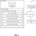
- FIG. 1 illustrates a system 100 configured for calibrating depth in a well to seismic data in a subsurface volume of interest, in accordance with one or more implementations.
- system 100 may include one or more servers 102.
- Server(s) 102 may be configured to communicate with one or more client computing platforms 104 according to a client/server architecture and/or other architectures.
- Client computing platform(s) 104 may be configured to communicate with other client computing platforms via server(s) 102 and/or according to a peer-to-peer architecture and/or other architectures. Users may access system 100 via client computing platform(s) 104.
- Server(s) 102 may be configured by machine-readable instructions 106.
- Machine-readable instructions 106 may include one or more instruction components.
- the instruction components may include computer program components.
- the instruction components may include one or more of a data component 108, a transform model component 110, a seismic trace component 112, a wavelet component 114, a calibration component 116, and/or other instruction components.
- Data component 108 may be configured to obtain well data corresponding to the well in the subsurface volume of interest.
- the well data specifies depth values of the well in the subsurface volume of interest.
- a subsurface volume of interest may include any area, region, and/or volume underneath a surface. Such a volume may include, or be bounded by, one or more of a water surface, a ground surface, and/or other surfaces.
- the well may be a production wellbore, injection wellbore, and/or other wellbore.
- FIG. 3A illustrates well data, in accordance with one or more implementations. As illustrated, original velocities are graphed along the x axis and corresponding depths are graphed on the y axis.
- data component 108 may be configured to convert the well data to converted well data.
- the converted well data specifies time values corresponding to the well data.
- Converting the well data to converted well data may include converting a top depth of the well to a corresponding time, t top .
- the time values may represent the subsurface energy travelling from a source to a given depth in the well in the subsurface volume of interest to a receiver device.
- checkshot velocities or seismic migration velocities may be used to determine t top .
- Checkshot velocities may be a measure of the travel from the surface to a known depth in a well by lowering seismic sources into the well.
- Seismic migration velocities may include migrating and/or shifting seismic traces to account for multiple, different offsets.
- FIG. 3B illustrates converted well data, in accordance with one or more implementations.
- well data may be converted into time values, graphed on the y axis and velocities are plotted on the x axis.
- seismic trace component 110 may be configured to obtain a seismic trace, corresponding to the well in the subsurface volume of interest, and a corresponding wavelet.
- the seismic trace specifies time values as a function of energy.
- the seismic trace may be subsurface data.
- the seismic trace may represent the subsurface energy travelling from a source to an interface in the subsurface volume of interest to a receiver device.
- Wavelet component 112 may be configured to apply the corresponding wavelet to the transformed well data to generate a modified signal. Applying the corresponding wavelet may include convolving the transformed well data. Convolution may, for example, involve convolving computed Zoeppritz reflection coefficients, as will be described herein, with the corresponding wavelet. The convolution may generate the modified signal. The modified signal may be a synthetic seismic or trace. It should be appreciated that wavelet component 112 may be used multiple times to apply multiple corresponding wavelets to multiple sets of transformed well data to generate multiple modified signals.
- FIG. 5 illustrates example transformed well data and an example modified signal, in accordance with one or more implementations.
- Applying the transform model to the converted well data generates transformed well data 502.
- Transformed well data 502 is used to generate modified signal 504.
- Modified signal 504 may be compared to a seismic trace (not shown). If, for example, modified signal 504 is the closest match, based on a correspondence, modified signal 504 and corresponding data may be selected to tie the well to the seismic trace.
- wavelet component 112 may be configured to generate the corresponding wavelet to a seismic trace.
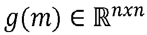
- the corresponding wavelet is generated by using the seismic trace and a given reflectivity g m ⁇ R n , where R may represent the set of all real numbers and m may represent the modified signal.
- Reflectivity may be the ratio of amplitude of the reflected subsurface energy to the source subsurface energy wave, or how much subsurface energy is reflected off a subsurface interface. This reflectivity is based on the contrast in velocity and density across the subsurface interface.
- a Toeplitz circulant matrix may be generated: g m ⁇ R nxn .
- s ⁇ ⁇ may represent the corresponding wavelet
- F may represent a Fourier transform
- G ⁇ ⁇ may represent the modified matrix of the one or more reflectivities
- d ⁇ ⁇ may represent the seismic trace.
- the least squares estimate of the corresponding wavelet may be used with a singular value decomposition pseudoinverse that may discard singular values below 10 -8 .
- the resulting matrix may be used for the Fourier transformed least squares estimate to generate the corresponding wavelet. It should be appreciated that different methods may be used to achieve maximum energy values concentrated near a time (e.g., about 0).
- Transform model component 114 may be configured to generate a transform model based on one or more probabilities.
- the transform model includes a slope parameter and a shift parameter.
- the transform model may be based, in part, on an inversion, a Markov chain Monte Carlo sampling process, and/or other techniques.
- the transform model may include one or more parameters to stretch and/or squeeze data, shift the data, and/or otherwise modify the data.
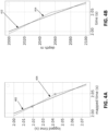
- FIG. 4A illustrates example model parameterizations, in accordance with one or more implementations. As illustrated, an original parameterization may be graphed as line 402. A transformed parameterization may be graphed as line 404 with three slopes, two pinch points and a bulk shift.
- FIG. 4B illustrates example transform models, in accordance with one or more implementations.
- Depth-time curve 412 corresponds to line 402 and depth-time curve 414 corresponds to line 404.
- Depth-time curve 404 may be the well-tying curve, if, for example, the modified signal is selected as a suitable match for the seismic trace.
- the transform model may include zero-phase low pass filtering interpolated log velocities at a frequency (e.g., about 100 Hz). It should be appreciated that different frequencies and/or other filtering techniques may be used for different applications.
- the transform model may include decimating filtered log velocities at a time (e.g., about 4 ms). It should be appreciated that different time values may be used to decimate the filtered log velocities for different applications.
- m represents an initial transform model
- m' represents the transform model
- p() represents a prior model probability for a given variable
- q() represents a proposal probability from a first variable to a second variable, represents a likelihood for a given transform model
- represents a determinant of a Jacobian of a transformation of variables while changing a number of slopes from the first transform model to the second transform model.
- a threshold probability value may be used to select a transform model from the multiple possible transform models.
- the transform model may need a fixed value for a symmetric perturbation of t top . For example, 5% of ⁇ t top may be used, based on a Gaussian proposal. It should be appreciated that other values may be used in different applications.
- p m ′ p m k + 1 ⁇ l 1 N ⁇ k p k + 1 p k and q m
- m ⁇ l N ⁇ k k + 1
- q m m ′ q m ′
- m ⁇ l N ⁇ k k + 1
- p m ′ p m ⁇ l k 1 N ⁇ k + 1 p k ⁇ 1 p k and q m
- the variables may use the same definitions as described above.
- d may represent the actual seismic trace
- t may represent a time value, such as, for example, converted well data
- C d may represent a covariance matrix between the noise in the data samples in the seismic trace. This may be a diagonal matrix, with diagonal entries providing an estimate of noise variance at corresponding time samples. Higher variance corresponds to lower signal to noise ratio.
- a Jacobian may be a matrix of first-order partial derivatives of a vector-valued function.
- the modification parameter includes one or more scalar values corresponding to one or more of an insertion of a given point between the one or more slopes in the converted well data, a deletion of the given point between the one or more slopes in the converted well data, a movement of the given point between the one or more slopes in the converted well data, a time shift of the converted well data, and/or other modifications to the converted well data.
- p(k) may equal 1 k .
- p(k) may equal 1 k .
- transform model component 114 may be configured to apply the transform model to the converted well data to transform the converted well data into transformed well data.
- the transformed well data specifies time values corresponding to the converted well data. It should be appreciated that transform model component 114 may be used multiple times to apply multiple transform models to the converted well data to transform the converted well data into multiple sets of transformed well data.
- Calibration component 116 may be configured to generate a correspondence between the modified signal and the seismic trace.
- the correspondence is a difference between the given modified signal and the seismic trace.
- the difference may be a mathematical difference between the modified signal and the seismic trace. It should be appreciated that calibration component 116 may be used multiple times to generate multiple correspondences between multiple modified signals and the seismic trace.
- calibration component 116 may be configured to select a given modified signal based on the correspondence between individual ones of the modified signals and the seismic trace.
- the given modified signal may be selected because the difference between the given modified signal and the seismic trace is the smallest compared to other modified signals. It should be appreciated that other factors may contribute to selecting the given modified signal, such as, for example, a highest probability based on the one or more probabilities, a corresponding likelihood, etc.
- calibration component 116 may be configured to calibrate the well data to the seismic trace based on a selected transformed well data corresponding to a selected modified signal.
- calibration component 116 may be configured to generate an uncertainty estimate for calibrating the well data to the seismic trace based on the multiple modified signals. Given that multiple transform models may be used to generate the multiple modified signals, uncertainty on the well ties may be generated based on the multiple, different properties corresponding to the multiple transform models.
- server(s) 102, client computing platform(s) 104, and/or external resources 128 may be operatively linked via one or more electronic communication links.
- electronic communication links may be established, at least in part, via a network 122 such as the Internet and/or other networks. It will be appreciated that this is not intended to be limiting, and that the scope of this disclosure includes implementations in which server(s) 102, client computing platform(s) 104, and/or external resources 128 may be operatively linked via some other communication media.
- a given client computing platform 104 may include one or more processors configured to execute computer program components.
- the computer program components may be configured to enable an expert or user associated with the given client computing platform 104 to interface with system 100 and/or external resources 128, and/or provide other functionality attributed herein to client computing platform(s) 104.
- the given client computing platform 104 may include one or more of a desktop computer, a laptop computer, a handheld computer, a tablet computing platform, a NetBook, a Smartphone, a gaming console, and/or other computing platforms.
- External resources 128 may include sources of information outside of system 100, external entities participating with system 100, and/or other resources. In some implementations, some or all of the functionality attributed herein to external resources 128 may be provided by resources included in system 100.
- Server(s) 102 may include electronic storage 130, one or more processors 132, and/or other components. Server(s) 102 may include communication lines, or ports to enable the exchange of information with a network and/or other computing platforms. Illustration of server(s) 102 in FIG. 1 is not intended to be limiting. Server(s) 102 may include a plurality of hardware, software, and/or firmware components operating together to provide the functionality attributed herein to server(s) 102. For example, server(s) 102 may be implemented by a cloud of computing platforms operating together as server(s) 102.
- Electronic storage 130 may include non-transitory storage media that electronically stores information.
- the electronic storage media of electronic storage 130 may include one or both of system storage that is provided integrally (i.e., substantially non-removable) with server(s) 102 and/or removable storage that is removably connectable to server(s) 102 via, for example, a port (e.g., a USB port, a firewire port, etc.) or a drive (e.g., a disk drive, etc.).
- a port e.g., a USB port, a firewire port, etc.
- a drive e.g., a disk drive, etc.
- Electronic storage 130 may include one or more of optically readable storage media (e.g., optical disks, etc.), magnetically readable storage media (e.g., magnetic tape, magnetic hard drive, floppy drive, etc.), electrical charge-based storage media (e.g., EEPROM, RAM, etc.), solid-state storage media (e.g., flash drive, etc.), non-transient electronic storage, and/or other electronically readable storage media.
- Electronic storage 130 may include one or more virtual storage resources (e.g., cloud storage, a virtual private network, and/or other virtual storage resources).
- Electronic storage 130 may store software algorithms, information determined by processor(s) 132, information received from server(s) 102, information received from client computing platform(s) 104, and/or other information that enables server(s) 102 to function as described herein.
- Processor(s) 132 may be configured to provide information processing capabilities in server(s) 102.
- processor(s) 132 may include one or more of a physical computer processor, a digital processor, an analog processor, a digital circuit designed to process information, an analog circuit designed to process information, a state machine, and/or other mechanisms for electronically processing information.
- processor(s) 132 is shown in FIG. 1 as a single entity, this is for illustrative purposes only.
- processor(s) 132 may include a plurality of processing units. These processing units may be physically located within the same device, or processor(s) 132 may represent processing functionality of a plurality of devices operating in coordination.
- Processor(s) 132 may be configured to execute components 108, 110, 112, 114, and/or 116, and/or other components.
- Processor(s) 132 may be configured to execute components 108, 110, 112, 114, and/or 116, and/or other components by software; hardware; firmware; some combination of software, hardware, and/or firmware; and/or other mechanisms for configuring processing capabilities on processor(s) 132.
- the term "component” may refer to any component or set of components that perform the functionality attributed to the component. This may include one or more physical processors during execution of processor readable instructions, the processor readable instructions, circuitry, hardware, storage media, or any other components.
- components 108, 110, 112, 114, and/or 116 are illustrated in FIG. 1 as being implemented within a single processing unit, in implementations in which processor(s) 132 includes multiple processing units, one or more of components 108, 110, 112, 114, and/or 116 may be implemented remotely from the other components.
- the description of the functionality provided by the different components 108, 110, 112, 114, and/or 116 described below is for illustrative purposes, and is not intended to be limiting, as any of components 108, 110, 112, 114, and/or 116 may provide more or less functionality than is described.
- processor(s) 132 may be configured to execute one or more additional components that may perform some or all of the functionality attributed below to one of components 108, 110, 112, 114, and/or 116.
- FIG. 2 illustrates a method 200 for calibrating depth in a well to seismic data in a subsurface volume of interest, in accordance with one or more implementations.
- the operations of method 200 presented below are intended to be illustrative. In some implementations, method 200 may be accomplished with one or more additional operations not described, and/or without one or more of the operations discussed. Additionally, the order in which the operations of method 200 are illustrated in FIG. 2 and described below is not intended to be limiting.
- Method 200 is implemented in one or more processing devices (e.g., a physical computer processor, a digital processor, an analog processor, a digital circuit designed to process information, an analog circuit designed to process information, a state machine, and/or other mechanisms for electronically processing information).
- the one or more processing devices may include one or more devices executing some or all of the operations of method 200 in response to instructions stored electronically on an electronic storage medium, such as, for example, non-transient electronic storage .
- the one or more processing devices may include one or more devices configured through hardware, firmware, and/or software to be specifically designed for execution of one or more of the operations of method 200.
- An operation 202 includes obtaining well data corresponding to the well in the subsurface volume of interest.
- the well data specifies depth values of the well in the subsurface volume of interest.
- Operation 202 may be performed by one or more processors configured by machine-readable instructions including a component that is the same as or similar to data component 108, in accordance with one or more implementations.
- An operation 204 includes converting the well data to converted well data.
- Operation 204 may be performed by one or more processors configured by machine-readable instructions including a component that is the same as or similar to data component 108, in accordance with one or more implementations.
- An operation 206 includes obtaining a seismic trace, corresponding to the well in the subsurface volume of interest, and a corresponding wavelet.
- the seismic trace specifies time values as a function of energy.
- the corresponding wavelet is generated by using the seismic trace.
- Operation 206 may be performed by one or more processors configured by machine-readable instructions including a component that is the same as or similar to seismic trace component 110, in accordance with one or more implementations.
- An operation 208 includes generating a transform model based on one or more probabilities.
- the transform model includes a slope parameter and a shift parameter.
- the modification parameter, ⁇ has one or more scalar values corresponding to one or more of an insertion of a slope in the converted well data, a deletion of the slope in the converted well data, a movement of the slope in the converted well data, a time shift of the converted well data, and/or other modifications.
- Example equations for the modification parameter, ⁇ are described in greater detail above. Operation 208 may be performed by one or more processors configured by machine-readable instructions including a component that is the same as or similar to transform model component 114, in accordance with one or more implementations.
- An operation 210 includes applying the transform model to the converted well data to transform the converted well data into transformed well data.
- the transformed well data specifies time values corresponding to the converted well data.
- Example transform models may be described in greater detail above. Operation 210 may be performed by one or more processors configured by machine-readable instructions including a component that is the same as or similar to data component 108, in accordance with one or more implementations.
- An operation 212 includes applying the corresponding wavelet to the transformed well data to generate a modified signal. Operation 212 may be performed by one or more processors configured by machine-readable instructions including a component that is the same as or similar to wavelet component 112, in accordance with one or more implementations.
- An operation 214 includes generating a correspondence between the modified signal and the seismic trace.
- the correspondence is a difference between the given modified signal and the seismic trace.
- Operation 214 may be performed by one or more processors configured by machine-readable instructions including a component that is the same as or similar to calibration component 116, in accordance with one or more implementations.
- An operation 216 includes repeating 208-214 to select a given modified signal, based on the correspondence between individual ones of the modified signals and the seismic trace. Operation 216 may be performed by one or more processors configured by machine-readable instructions including a component that is the same as or similar to calibration component 116, in accordance with one or more implementations.
- An operation 218 may include calibrating the well data to the seismic trace based on a selected transformed well data corresponding to a selected modified signal.
- the calibration may include an uncertainty estimate based on the multiple modified signals.
- Operation 218 may be performed by one or more processors configured by machine-readable instructions including a component that is the same as or similar to calibration component 116, in accordance with one or more implementations.
Landscapes
- Physics & Mathematics (AREA)
- Life Sciences & Earth Sciences (AREA)
- Engineering & Computer Science (AREA)
- Remote Sensing (AREA)
- General Life Sciences & Earth Sciences (AREA)
- General Physics & Mathematics (AREA)
- Geophysics (AREA)
- Acoustics & Sound (AREA)
- Environmental & Geological Engineering (AREA)
- Geology (AREA)
- Manufacturing & Machinery (AREA)
- Geophysics And Detection Of Objects (AREA)
Description
- The present disclosure relates to methods and systems for calibrating depth in a well to seismic data in a subsurface volume of interest.
- Seismic well ties are an essential step in a seismic interpretation workflow to establish correspondence between reflectors in seismic time and logged well depth. Tying well depth to seismic time requires stretching, squeezing, and/or shifting logged wellbore seismic impedance so resulting synthetic seismic closely match the observed seismic data. Existing technologies use manual processes to tie well depth to seismic times.
Reference may be made to R. H. HERRERA ET AL: "Automatic approaches for seismic to well tying", INTERPRETATION, vol. 2, no. 2, 10 April 2014, pages SD9-SD17, which relates to a dynamic time warping method, and using a local similarity attribute based on regularized shaping filters. These methods produce a guided stretching and squeezing process to find the best match between two signals. The proposed methods are explored using real well log examples and compared to the manual method. Reference may be made to R. WHITE AND R. SIMM: "Tutorial: Good practice in well ties", First Break, vol. 21, 1 October 2003, pages 75-83, which relates to a process by which wavelets are estimated through a well tie procedure that results in quantitative measures of synthetic to seismic goodness-of-fit and likely wavelet accuracy. Reference may be made to J. GUNNING AND M.E. GLINSKY: "Wavelet extractor: A Bayesian well-tie and wavelet extraction program", COMPUTERS & GEOSCIENCES, vol. 32, no. 5, 1 June 2006, pages 681-695, which relates to a new open-source toolkit for the well-tie or wavelet extraction problem of estimating seismic wavelets from seismic data, time-to-depth information, and well-log suites. The wavelet extraction model is formulated as a Bayesian inverse problem, and the software will simultaneously estimate wavelet coefficients, other parameters associated with uncertainty in the time-to-depth mapping, positioning errors in the seismic imaging, and useful amplitude-variation-with-offset (AVO) related parameters in multi-stack extractions. - The present invention is defined by the appended independent claims to which reference should now be made. Specific embodiments are defined in the dependent claims. One arrangement of the present disclosure relates to a method for calibrating depth in a well to seismic data in a subsurface volume of interest.
- An arrangement of the present disclosure relates to a system configured for calibrating depth in a well to seismic data in a subsurface volume of interest. The system includes one or more hardware processors configured by machine-readable instructions.
- An arrangement of the present disclosure relates to a non-transient computer-readable medium having instructions embodied thereon, the instructions being executable by one or more processors to perform a method for calibrating depth in a well to seismic data in a subsurface volume of interest.
- These and other features, and characteristics of the present technology, as well as the methods of operation and functions of the related elements of structure and the combination of parts and economies of manufacture, will become more apparent upon consideration of the following description and the appended claims with reference to the accompanying drawings, all of which form a part of this specification, wherein like reference numerals designate corresponding parts in the various figures. It is to be expressly understood, however, that the drawings are for the purpose of illustration and description only and are not intended as a definition of the limits of the presently disclosed technology. As used in the specification and in the claims, the singular form of 'a', 'an', and 'the' include plural referents unless the context clearly dictates otherwise.
-
-
FIG. 1 illustrates a system configured for calibrating depth in a well to seismic data in a subsurface volume of interest, in accordance with one or more implementations. -
FIG. 2 illustrates a method for calibrating depth in a well to seismic data in a subsurface volume of interest, in accordance with one or more implementations. -
FIG. 3A illustrates well data, in accordance with one or more implementations. -
FIG. 3B illustrates converted well data, in accordance with one or more implementations. -
FIG. 4A illustrates example model parameterizations, in accordance with one or more implementations. -
FIG. 4B illustrates example transform models, in accordance with one or more implementations s. -
FIG. 5 illustrates example transformed well data and an example modified signal, in accordance with one or more implementations. - Disclosed are systems and methods for calibrating depth in a well to seismic data in a subsurface volume of interest. The disclosed technology uses an iterative probabilistic inverse process to simultaneously estimate the wavelet and tie wells, while staying within prior geological bounds. This method reduces the time required to generate a seismic-to-well-tie, quantifies a corresponding uncertainty, and refocuses time and energy on interpretation of the ties and its implications for seismic velocity and/or well log quality. The method includes converting well data into a time format. The method includes using a transform model, generated based on one or more probabilities, to transform the converted well data into transformed well data that will be used for a synthetic seismic. The method includes estimating a seismic wavelet, and/or obtaining a seismic wavelet, to apply to the transformed well data to generate a synthetic seismic, or modified signal. The method includes repeating this multiple times and comparing different modified signals corresponding to different transform models to the seismic trace until a suitable match is found. The method may, based on the matching sets of synthetic seismic data, tie the well data to the seismic data multiple times.
-
FIG. 1 illustrates asystem 100 configured for calibrating depth in a well to seismic data in a subsurface volume of interest, in accordance with one or more implementations. In some implementations,system 100 may include one ormore servers 102. Server(s) 102 may be configured to communicate with one or moreclient computing platforms 104 according to a client/server architecture and/or other architectures. Client computing platform(s) 104 may be configured to communicate with other client computing platforms via server(s) 102 and/or according to a peer-to-peer architecture and/or other architectures. Users may accesssystem 100 via client computing platform(s) 104. - Server(s) 102 may be configured by machine-
readable instructions 106. Machine-readable instructions 106 may include one or more instruction components. The instruction components may include computer program components. The instruction components may include one or more of adata component 108, atransform model component 110, aseismic trace component 112, awavelet component 114, acalibration component 116, and/or other instruction components. -
Data component 108 may be configured to obtain well data corresponding to the well in the subsurface volume of interest. The well data specifies depth values of the well in the subsurface volume of interest. A subsurface volume of interest may include any area, region, and/or volume underneath a surface. Such a volume may include, or be bounded by, one or more of a water surface, a ground surface, and/or other surfaces. The well may be a production wellbore, injection wellbore, and/or other wellbore. For example,FIG. 3A illustrates well data, in accordance with one or more implementations. As illustrated, original velocities are graphed along the x axis and corresponding depths are graphed on the y axis. - In implementations,
data component 108 may be configured to convert the well data to converted well data. The converted well data specifies time values corresponding to the well data. Converting the well data to converted well data may include converting a top depth of the well to a corresponding time, ttop . Converting the well data to converted well data may include using the following equation
- For example,
FIG. 3B illustrates converted well data, in accordance with one or more implementations. As illustrated, well data may be converted into time values, graphed on the y axis and velocities are plotted on the x axis. - Referring back to
FIG. 1 ,seismic trace component 110 may be configured to obtain a seismic trace, corresponding to the well in the subsurface volume of interest, and a corresponding wavelet. The seismic trace specifies time values as a function of energy. The seismic trace may be subsurface data. The seismic trace may represent the subsurface energy travelling from a source to an interface in the subsurface volume of interest to a receiver device. -
Wavelet component 112 may be configured to apply the corresponding wavelet to the transformed well data to generate a modified signal. Applying the corresponding wavelet may include convolving the transformed well data. Convolution may, for example, involve convolving computed Zoeppritz reflection coefficients, as will be described herein, with the corresponding wavelet. The convolution may generate the modified signal. The modified signal may be a synthetic seismic or trace. It should be appreciated thatwavelet component 112 may be used multiple times to apply multiple corresponding wavelets to multiple sets of transformed well data to generate multiple modified signals. - For example,
FIG. 5 illustrates example transformed well data and an example modified signal, in accordance with one or more implementations. Applying the transform model to the converted well data generates transformedwell data 502. Transformed welldata 502 is used to generate modifiedsignal 504.Modified signal 504 may be compared to a seismic trace (not shown). If, for example, modifiedsignal 504 is the closest match, based on a correspondence, modifiedsignal 504 and corresponding data may be selected to tie the well to the seismic trace. - In implementations,
wavelet component 112 may be configured to generate the corresponding wavelet to a seismic trace. The corresponding wavelet is generated by using the seismic trace and a given reflectivity



- The matrix may be refined and columns corresponding to the n - 2m rows of zero padding may be removed, generating


- A Fourier transform may be applied to the least squares estimate of the corresponding wavelet, resulting in


-
Transform model component 114 may be configured to generate a transform model based on one or more probabilities. The transform model includes a slope parameter and a shift parameter. The transform model may be based, in part, on an inversion, a Markov chain Monte Carlo sampling process, and/or other techniques. For example, the transform model may include one or more parameters to stretch and/or squeeze data, shift the data, and/or otherwise modify the data. One example of a transform model may be
where t' may represent transformed time (e.g., transformed well data specifying time values corresponding to the converted well data), t may represent a target time (e.g., converted well data specifying time values corresponding to the well data), and l may represent a slope. In implementations, the new curve t' may be specified by one or more piecewise linear sections. For example,FIG. 4A illustrates example model parameterizations, in accordance with one or more implementations. As illustrated, an original parameterization may be graphed asline 402. A transformed parameterization may be graphed asline 404 with three slopes, two pinch points and a bulk shift. -
FIG. 4B illustrates example transform models, in accordance with one or more implementations. Depth-time curve 412 corresponds toline 402 and depth-time curve 414 corresponds toline 404. Depth-time curve 404 may be the well-tying curve, if, for example, the modified signal is selected as a suitable match for the seismic trace. - Referring back to transform
model component 114, in implementations, the transform model may include linearly interpolating log velocities at a time (e.g., about 1 ms). It should be appreciated that other times may be used for different applications. Log velocities may be obtained from compressional velocities, density, and/or shear speed at time t' that may be the original logged velocities at the corresponding depth z. Based on the equation,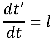


- The transform model may include zero-phase low pass filtering interpolated log velocities at a frequency (e.g., about 100 Hz). It should be appreciated that different frequencies and/or other filtering techniques may be used for different applications. The transform model may include decimating filtered log velocities at a time (e.g., about 4 ms). It should be appreciated that different time values may be used to decimate the filtered log velocities for different applications.
- In some implementations, one of the one or more probabilities used to generate the transform model may be based on, for example,
 represents a likelihood for a given transform model, and |J| represents a determinant of a Jacobian of a transformation of variables while changing a number of slopes from the first transform model to the second transform model. In some implementations, a threshold probability value may be used to select a transform model from the multiple possible transform models.
- A prior model probability may be defined by, for example,

- In implementations,


- In implementations,


- A likelihood for the given transform model may be defined by

- In some implementations, the likelihood for the given transform model may be approximated by

- With respect to the probability equation above, a Jacobian may be a matrix of first-order partial derivatives of a vector-valued function.
- One of the one or more probabilities used to accept the transform model is based on,
 represents a likelihood for the transform model. In implementations, the example transform model equation above may be the likelihood ratio. For example, when p(k) may be constant for k=0, ..., kmax, p(k) may be the likelihood ratio.
 - β, the modification parameter, includes one or more scalar values corresponding to one or more of an insertion of a given point between the one or more slopes in the converted well data, a deletion of the given point between the one or more slopes in the converted well data, a movement of the given point between the one or more slopes in the converted well data, a time shift of the converted well data, and/or other modifications to the converted well data. For example, the modification parameter may be defined by


- In one example, the modification parameter may be defined by


- In implementations, transform
model component 114 may be configured to apply the transform model to the converted well data to transform the converted well data into transformed well data. The transformed well data specifies time values corresponding to the converted well data. It should be appreciated that transformmodel component 114 may be used multiple times to apply multiple transform models to the converted well data to transform the converted well data into multiple sets of transformed well data. -
Calibration component 116 may be configured to generate a correspondence between the modified signal and the seismic trace. The correspondence is a difference between the given modified signal and the seismic trace. For example, the difference may be a mathematical difference between the modified signal and the seismic trace. It should be appreciated thatcalibration component 116 may be used multiple times to generate multiple correspondences between multiple modified signals and the seismic trace. - In implementations,
calibration component 116 may be configured to select a given modified signal based on the correspondence between individual ones of the modified signals and the seismic trace. The given modified signal may be selected because the difference between the given modified signal and the seismic trace is the smallest compared to other modified signals. It should be appreciated that other factors may contribute to selecting the given modified signal, such as, for example, a highest probability based on the one or more probabilities, a corresponding likelihood, etc. - In implementations,
calibration component 116 may be configured to calibrate the well data to the seismic trace based on a selected transformed well data corresponding to a selected modified signal. - In some implementations,
calibration component 116 may be configured to generate an uncertainty estimate for calibrating the well data to the seismic trace based on the multiple modified signals. Given that multiple transform models may be used to generate the multiple modified signals, uncertainty on the well ties may be generated based on the multiple, different properties corresponding to the multiple transform models. - In some implementations, server(s) 102, client computing platform(s) 104, and/or
external resources 128 may be operatively linked via one or more electronic communication links. For example, such electronic communication links may be established, at least in part, via anetwork 122 such as the Internet and/or other networks. It will be appreciated that this is not intended to be limiting, and that the scope of this disclosure includes implementations in which server(s) 102, client computing platform(s) 104, and/orexternal resources 128 may be operatively linked via some other communication media. - A given
client computing platform 104 may include one or more processors configured to execute computer program components. The computer program components may be configured to enable an expert or user associated with the givenclient computing platform 104 to interface withsystem 100 and/orexternal resources 128, and/or provide other functionality attributed herein to client computing platform(s) 104. By way of non-limiting example, the givenclient computing platform 104 may include one or more of a desktop computer, a laptop computer, a handheld computer, a tablet computing platform, a NetBook, a Smartphone, a gaming console, and/or other computing platforms. -
External resources 128 may include sources of information outside ofsystem 100, external entities participating withsystem 100, and/or other resources. In some implementations, some or all of the functionality attributed herein toexternal resources 128 may be provided by resources included insystem 100. - Server(s) 102 may include
electronic storage 130, one ormore processors 132, and/or other components. Server(s) 102 may include communication lines, or ports to enable the exchange of information with a network and/or other computing platforms. Illustration of server(s) 102 inFIG. 1 is not intended to be limiting. Server(s) 102 may include a plurality of hardware, software, and/or firmware components operating together to provide the functionality attributed herein to server(s) 102. For example, server(s) 102 may be implemented by a cloud of computing platforms operating together as server(s) 102. -
Electronic storage 130 may include non-transitory storage media that electronically stores information. The electronic storage media ofelectronic storage 130 may include one or both of system storage that is provided integrally (i.e., substantially non-removable) with server(s) 102 and/or removable storage that is removably connectable to server(s) 102 via, for example, a port (e.g., a USB port, a firewire port, etc.) or a drive (e.g., a disk drive, etc.).Electronic storage 130 may include one or more of optically readable storage media (e.g., optical disks, etc.), magnetically readable storage media (e.g., magnetic tape, magnetic hard drive, floppy drive, etc.), electrical charge-based storage media (e.g., EEPROM, RAM, etc.), solid-state storage media (e.g., flash drive, etc.), non-transient electronic storage, and/or other electronically readable storage media.Electronic storage 130 may include one or more virtual storage resources (e.g., cloud storage, a virtual private network, and/or other virtual storage resources).Electronic storage 130 may store software algorithms, information determined by processor(s) 132, information received from server(s) 102, information received from client computing platform(s) 104, and/or other information that enables server(s) 102 to function as described herein. - Processor(s) 132 may be configured to provide information processing capabilities in server(s) 102. As such, processor(s) 132 may include one or more of a physical computer processor, a digital processor, an analog processor, a digital circuit designed to process information, an analog circuit designed to process information, a state machine, and/or other mechanisms for electronically processing information. Although processor(s) 132 is shown in
FIG. 1 as a single entity, this is for illustrative purposes only. In some implementations, processor(s) 132 may include a plurality of processing units. These processing units may be physically located within the same device, or processor(s) 132 may represent processing functionality of a plurality of devices operating in coordination. Processor(s) 132 may be configured to executecomponents components - It should be appreciated that although
components FIG. 1 as being implemented within a single processing unit, in implementations in which processor(s) 132 includes multiple processing units, one or more ofcomponents different components components components components components -
FIG. 2 illustrates amethod 200 for calibrating depth in a well to seismic data in a subsurface volume of interest, in accordance with one or more implementations. The operations ofmethod 200 presented below are intended to be illustrative. In some implementations,method 200 may be accomplished with one or more additional operations not described, and/or without one or more of the operations discussed. Additionally, the order in which the operations ofmethod 200 are illustrated inFIG. 2 and described below is not intended to be limiting. -
Method 200 is implemented in one or more processing devices (e.g., a physical computer processor, a digital processor, an analog processor, a digital circuit designed to process information, an analog circuit designed to process information, a state machine, and/or other mechanisms for electronically processing information). The one or more processing devices may include one or more devices executing some or all of the operations ofmethod 200 in response to instructions stored electronically on an electronic storage medium, such as, for example, non-transient electronic storage . The one or more processing devices may include one or more devices configured through hardware, firmware, and/or software to be specifically designed for execution of one or more of the operations ofmethod 200. - An
operation 202 includes obtaining well data corresponding to the well in the subsurface volume of interest. The well data specifies depth values of the well in the subsurface volume of interest.Operation 202 may be performed by one or more processors configured by machine-readable instructions including a component that is the same as or similar todata component 108, in accordance with one or more implementations. - An
operation 204 includes converting the well data to converted well data. In some implementations, converting the well data to converted well data may include converting a top depth of the well to a corresponding time, ttop . and generating the converted well data using
Operation 204 may be performed by one or more processors configured by machine-readable instructions including a component that is the same as or similar todata component 108, in accordance with one or more implementations. - An
operation 206 includes obtaining a seismic trace, corresponding to the well in the subsurface volume of interest, and a corresponding wavelet. The seismic trace specifies time values as a function of energy. The corresponding wavelet is generated by using the seismic trace. For example, the corresponding wavelet may be defined by
Operation 206 may be performed by one or more processors configured by machine-readable instructions including a component that is the same as or similar toseismic trace component 110, in accordance with one or more implementations. - An
operation 208 includes generating a transform model based on one or more probabilities. The transform model includes a slope parameter and a shift parameter. The one or more probabilities may include


Operation 208 may be performed by one or more processors configured by machine-readable instructions including a component that is the same as or similar to transformmodel component 114, in accordance with one or more implementations. - An
operation 210 includes applying the transform model to the converted well data to transform the converted well data into transformed well data. The transformed well data specifies time values corresponding to the converted well data. Example transform models may be described in greater detail above.Operation 210 may be performed by one or more processors configured by machine-readable instructions including a component that is the same as or similar todata component 108, in accordance with one or more implementations. - An
operation 212 includes applying the corresponding wavelet to the transformed well data to generate a modified signal.Operation 212 may be performed by one or more processors configured by machine-readable instructions including a component that is the same as or similar towavelet component 112, in accordance with one or more implementations. - An
operation 214 includes generating a correspondence between the modified signal and the seismic trace. The correspondence is a difference between the given modified signal and the seismic trace.Operation 214 may be performed by one or more processors configured by machine-readable instructions including a component that is the same as or similar tocalibration component 116, in accordance with one or more implementations. - An
operation 216 includes repeating 208-214 to select a given modified signal, based on the correspondence between individual ones of the modified signals and the seismic trace.Operation 216 may be performed by one or more processors configured by machine-readable instructions including a component that is the same as or similar tocalibration component 116, in accordance with one or more implementations. - An
operation 218 may include calibrating the well data to the seismic trace based on a selected transformed well data corresponding to a selected modified signal. The calibration may include an uncertainty estimate based on the multiple modified signals.Operation 218 may be performed by one or more processors configured by machine-readable instructions including a component that is the same as or similar tocalibration component 116, in accordance with one or more implementations. - Although the present technology has been described in detail for the purpose of illustration based on what is currently considered to be the most practical and preferred implementations, it is to be understood that such detail is solely for that purpose and that the technology is not limited to the disclosed.implementations. It should be noted and understood that modifications of the implementations described above may be made, within the scope of the present invention as defined by the appended claims.
Claims (13)
- A computer-implemented method (200) for calibrating depth in a well to observed seismic data in a subsurface volume of interest, the method (200) being implemented in a computer system that includes one or more physical computer processors and non-transient electronic storage, comprising:a) obtaining (202), from the non-transient electronic storage, well data corresponding to the well in the subsurface volume of interest, wherein the well data comprises logged well depths specifying depth values of the well in the subsurface volume of interest;b) converting (204), with the one or more physical computer processors, the well data to converted well data, wherein the converted well data specifies time values corresponding to the well data;c) obtaining (206), from the non-transient electronic storage, a seismic trace, corresponding to the well in the subsurface volume of interest, and a corresponding wavelet, wherein the seismic trace specifies time values as a function of energy, wherein obtaining the corresponding wavelet includes generating the corresponding wavelet using the seismic trace and reflectivity based on contrast in velocity and density across a subsurface interface, the reflectivity indicating how much subsurface energy is reflected off the subsurface interface;d) generating (208), with the one or more physical computer processors, a transform model based on one or more probabilities and a modification parameter having scalar values corresponding to one or more of an insertion of a slope in the converted well data, a deletion of the slope in the converted well data, a movement of the slope in the converted well data, and a time shift of the converted well data, wherein the transform model includes a slope parameter and a shift parameter;e) applying (210), with the one or more physical computer processors, the transform model to the converted well data to transform the converted well data into transformed well data, wherein the transformed well data specifies time values corresponding to the converted well data;f) applying (212), with the one or more physical computer processors, the corresponding wavelet to the transformed well data to generate a modified signal;g) generating (214), with the one or more physical computer processors, a correspondence between the modified signal and the seismic trace, wherein the correspondence is a difference between the modified signal and the seismic trace; andh) repeating (216), with the one or more physical computer processors, steps d) - g) to select a given modified signal and the corresponding transformed well data to tie the well to the seismic trace, based on the correspondence between individual ones of the modified signals and the seismic trace,wherein one of the one or more probabilities used to generate a second transform model, m', is based on a probability, α:
 represents a likelihood for a given transform model.
- The computer-implemented method (200) of claim 1, further comprising:
calibrating (218), with the one or more physical computer processors, the well data to the seismic trace based on a selected set of transformed well data corresponding to a selected modified signal. - The computer-implemented method (200) of claim 2, further comprising:
generating, with the one or more physical computer processors, an uncertainty estimate for calibrating the well data to the seismic trace based on the multiple modified signals. - The computer-implemented method (200) of claim 1, wherein the corresponding wavelet,



- The computer-implemented method (200) of claim 1, wherein one of the one or more probabilities used to generate a second transform model, m', is based on a probability, α:
 represents a likelihood for a given transform model, and J represents a determinant of a Jacobian of a transformation of variables while changing a number of slopes from the first transform model to the second transform model.
 - The computer-implemented method (200) of claim 1, wherein the modification parameter, β, for the insertion of a point between slopes is

- The computer-implemented method (200) of claim 1, wherein the modification parameter, β, for the deletion of a point between slopes is

- The computer-implemented method (200) of claim 1, wherein the modification parameter, β, for the movement of a point between slopes or a time shift of the well data, in time, is equal to 1.
- The computer-implemented method (200) of claim 1, wherein one of the one or more probabilities used to generate a given transform model, m, is:

- The computer-implemented method (200) of claim 1, wherein converting the multiple depth values of the well data to time values comprises:converting a top depth of the well to a corresponding time, ttop ; andgenerating the converted well data using

- A system (100) for calibrating depth in a well to seismic data in a subsurface volume of interest, the system (100) comprising:non-transient electronic storage (130); andone or more physical computer processors (132) configured by machine-readable instructions to carry out the method of any of the preceding claims.
- One or more computer programs comprising instructions which, when carried out by a computer, cause the computer to carry out the method of any of claims 1 to 10.
- A computer-readable storage medium having the one or more computer programs of claim 12 stored thereon.
Applications Claiming Priority (2)
| Application Number | Priority Date | Filing Date | Title |
|---|---|---|---|
| US16/227,944 US11275193B2 (en) | 2018-12-20 | 2018-12-20 | Methods and systems for calibrating depth in a well to seismic data in a subsurface volume of interest |
| PCT/US2019/064921 WO2020131424A1 (en) | 2018-12-20 | 2019-12-06 | Methods and systems for calibrating depth in a well to seismic data in a subsurface volume of interest |
Publications (3)
| Publication Number | Publication Date |
|---|---|
| EP3899592A1 EP3899592A1 (en) | 2021-10-27 |
| EP3899592A4 EP3899592A4 (en) | 2022-08-17 |
| EP3899592B1 true EP3899592B1 (en) | 2024-11-20 |
Family
ID=71099327
Family Applications (1)
| Application Number | Title | Priority Date | Filing Date |
|---|---|---|---|
| EP19899826.2A Active EP3899592B1 (en) | 2018-12-20 | 2019-12-06 | Method and system for calibrating depth in a well to seismic data in a subsurface volume of interest |
Country Status (4)
| Country | Link |
|---|---|
| US (1) | US11275193B2 (en) |
| EP (1) | EP3899592B1 (en) |
| AU (1) | AU2019406345B2 (en) |
| WO (1) | WO2020131424A1 (en) |
Families Citing this family (7)
| Publication number | Priority date | Publication date | Assignee | Title |
|---|---|---|---|---|
| US12092783B2 (en) | 2020-09-22 | 2024-09-17 | Chevron U.S.A. Inc. | Systems and methods for generating subsurface property data as a function of position and time in a subsurface volume of interest |
| US12481079B2 (en) | 2020-09-22 | 2025-11-25 | Chevron U.S.A. Inc. | Systems and methods for generating elastic property data as a function of position and time in a subsurface volume of interest |
| US11733414B2 (en) * | 2020-09-22 | 2023-08-22 | Chevron U.S.A. Inc. | Systems and methods for generating subsurface data as a function of position and time in a subsurface volume of interest |
| CN114355451B (en) * | 2022-01-07 | 2024-08-20 | 西南石油大学 | Well earthquake calibration method based on multi-channel earthquake superposition |
| CN114545523B (en) * | 2022-02-25 | 2023-03-24 | 成都理工大学 | Depth domain well logging and seismic data direct calibration method |
| CN116719099B (en) * | 2023-06-12 | 2025-12-05 | 西南石油大学 | A precise well-seismic calibration method based on step-by-step matching optimization |
| CN119556338B (en) * | 2024-11-27 | 2026-02-24 | 成都理工大学 | A method for characterizing reservoir boundaries in transient matching squeeze transformation |
Family Cites Families (12)
| Publication number | Priority date | Publication date | Assignee | Title |
|---|---|---|---|---|
| US5691958A (en) | 1995-04-13 | 1997-11-25 | Exxon Production Research Company | Method for determining formation properties from seismic attributes |
| US7082367B2 (en) | 2004-07-02 | 2006-07-25 | Veritas Dgc Inc. | Seismic data calibration using crossplotted AVO attributes |
| US9223041B2 (en) * | 2008-01-23 | 2015-12-29 | Schlubmerger Technology Corporation | Three-dimensional mechanical earth modeling |
| WO2009142872A1 (en) | 2008-05-22 | 2009-11-26 | Exxonmobil Upstream Research Company | Seismic horizon skeletonization |
| US8649980B2 (en) | 2010-03-05 | 2014-02-11 | Vialogy Llc | Active noise injection computations for improved predictability in oil and gas reservoir characterization and microseismic event analysis |
| US9945970B1 (en) | 2011-08-29 | 2018-04-17 | Seismic Innovations | Method and apparatus for modeling microseismic event location estimate accuracy |
| US10977396B2 (en) * | 2012-01-13 | 2021-04-13 | Schlumberger Technology Corporation | Determining an elastic model for a geologic region |
| GB2505042B (en) * | 2012-06-13 | 2014-10-08 | Schlumberger Holdings | Seismic trace attribute |
| CN105445802A (en) | 2014-09-04 | 2016-03-30 | 中国石油化工股份有限公司 | High-precision time-depth correction method based on time-frequency spectrum constraints |
| US20170248716A1 (en) | 2014-11-14 | 2017-08-31 | Cgg Services Sas | Device and method for weighted sparse inversion for seismic processing |
| US10295683B2 (en) * | 2016-01-05 | 2019-05-21 | Schlumberger Technology Corporation | Amplitude inversion on partitioned depth image gathers using point spread functions |
| CN108562938B (en) | 2018-03-23 | 2019-09-06 | 中国石油天然气股份有限公司 | Method, device and system for eliminating frequency dispersion effect |
-
2018
- 2018-12-20 US US16/227,944 patent/US11275193B2/en active Active
-
2019
- 2019-12-06 AU AU2019406345A patent/AU2019406345B2/en active Active
- 2019-12-06 WO PCT/US2019/064921 patent/WO2020131424A1/en not_active Ceased
- 2019-12-06 EP EP19899826.2A patent/EP3899592B1/en active Active
Also Published As
| Publication number | Publication date |
|---|---|
| EP3899592A4 (en) | 2022-08-17 |
| US11275193B2 (en) | 2022-03-15 |
| EP3899592A1 (en) | 2021-10-27 |
| US20200200935A1 (en) | 2020-06-25 |
| WO2020131424A1 (en) | 2020-06-25 |
| AU2019406345A1 (en) | 2021-06-17 |
| AU2019406345B2 (en) | 2022-09-29 |
Similar Documents
| Publication | Publication Date | Title |
|---|---|---|
| US11275193B2 (en) | Methods and systems for calibrating depth in a well to seismic data in a subsurface volume of interest | |
| CN103703391B (en) | System of full wavefield inversion using spectral shaping and computer implementing method | |
| Gholami | A fast automatic multichannel blind seismic inversion for high-resolution impedance recovery | |
| Sen et al. | Transdimensional seismic inversion using the reversible jump Hamiltonian Monte Carlo algorithm | |
| Gholami | Nonlinear multichannel impedance inversion by total-variation regularization | |
| Esser et al. | Constrained waveform inversion for automatic salt flooding | |
| JP7019713B2 (en) | Continuous seismic reservoir monitoring using common focus method | |
| EP3776270B1 (en) | Systems and methods for using probabilities of lithologies in an inversion | |
| WO2012170090A1 (en) | System and method for data inversion with phase unwrapping | |
| EP2718744A1 (en) | System and method for seismic data inversion | |
| EP4446782A2 (en) | Systems and methods for refining estimated parameter values in seismic imaging | |
| EP3211594B1 (en) | Seismic modeling system providing seismic survey data inpainting based upon suspect region boundary comparisons and related methods | |
| Herrmann et al. | Frugal full-waveform inversion: From theory to a practical algorithm | |
| Lundsgaard et al. | Joint Bayesian wavelet and well-path estimation in the impedance domain | |
| Chen et al. | Unsupervised seismic acoustic impedance inversion based on generative diffusion model | |
| EP3217354B1 (en) | Seismic modeling system providing seismic survey data frequency domain inpainting and related methods | |
| CN106547021B (en) | The method and apparatus for establishing initial model based on individual well convolution algorithm | |
| EP2496968B1 (en) | System and method for seismic beam formation that accounts for equipment misalignment | |
| CN119716979B (en) | Seismic wave impedance high-resolution inversion method, device, equipment and storage medium based on physical model constraints | |
| CN106199714B (en) | The method and apparatus that the equivalent dominant frequency of geological data calculates | |
| Wang et al. | Bayesian reverse time migration with quantified uncertainty | |
| Hu et al. | Accelerating seismic inversion and uncertainty quantification with efficient high-rank Hessian approximations | |
| Alfayez et al. | Diffusion model priors in ensemble smoother seismic inversion | |
| Class et al. | Patent application title: Convergence Rate of Full Wavefield Inversion Using Spectral Shaping Inventors: Partha S. Routh (Katy, TX, US) Partha S. Routh (Katy, TX, US) Spyridon K. Lazaratos (Houston, TX, US) Anatoly Baumstein (Houston, TX, US) Anatoly Baumstein (Houston, TX, US) Ivan Chikichev (Houston, TX, US) Ke Wang (Sugar Land, TX, US) Ke Wang (Sugar Land, TX, US) | |
| Ustad et al. | Creating Singularity Order Attribute of Seismic Signals Using Continuous Wavelet Transform (CWT) for Stratigraphic Interpretation Tools |
Legal Events
| Date | Code | Title | Description |
|---|---|---|---|
| STAA | Information on the status of an ep patent application or granted ep patent |
Free format text: STATUS: THE INTERNATIONAL PUBLICATION HAS BEEN MADE |
|
| PUAI | Public reference made under article 153(3) epc to a published international application that has entered the european phase |
Free format text: ORIGINAL CODE: 0009012 |
|
| STAA | Information on the status of an ep patent application or granted ep patent |
Free format text: STATUS: REQUEST FOR EXAMINATION WAS MADE |
|
| 17P | Request for examination filed |
Effective date: 20210527 |
|
| AK | Designated contracting states |
Kind code of ref document: A1 Designated state(s): AL AT BE BG CH CY CZ DE DK EE ES FI FR GB GR HR HU IE IS IT LI LT LU LV MC MK MT NL NO PL PT RO RS SE SI SK SM TR |
|
| DAV | Request for validation of the european patent (deleted) | ||
| DAX | Request for extension of the european patent (deleted) | ||
| A4 | Supplementary search report drawn up and despatched |
Effective date: 20220719 |
|
| RIC1 | Information provided on ipc code assigned before grant |
Ipc: G01V 1/48 20060101ALI20220713BHEP Ipc: G01V 1/28 20060101ALI20220713BHEP Ipc: G01V 1/30 20060101AFI20220713BHEP |
|
| P01 | Opt-out of the competence of the unified patent court (upc) registered |
Effective date: 20230522 |
|
| STAA | Information on the status of an ep patent application or granted ep patent |
Free format text: STATUS: EXAMINATION IS IN PROGRESS |
|
| 17Q | First examination report despatched |
Effective date: 20240214 |
|
| GRAP | Despatch of communication of intention to grant a patent |
Free format text: ORIGINAL CODE: EPIDOSNIGR1 |
|
| STAA | Information on the status of an ep patent application or granted ep patent |
Free format text: STATUS: GRANT OF PATENT IS INTENDED |
|
| INTG | Intention to grant announced |
Effective date: 20240709 |
|
| RAP3 | Party data changed (applicant data changed or rights of an application transferred) |
Owner name: CHEVRON U.S.A. INC. |
|
| GRAS | Grant fee paid |
Free format text: ORIGINAL CODE: EPIDOSNIGR3 |
|
| GRAA | (expected) grant |
Free format text: ORIGINAL CODE: 0009210 |
|
| STAA | Information on the status of an ep patent application or granted ep patent |
Free format text: STATUS: THE PATENT HAS BEEN GRANTED |
|
| AK | Designated contracting states |
Kind code of ref document: B1 Designated state(s): AL AT BE BG CH CY CZ DE DK EE ES FI FR GB GR HR HU IE IS IT LI LT LU LV MC MK MT NL NO PL PT RO RS SE SI SK SM TR |
|
| REG | Reference to a national code |
Ref country code: GB Ref legal event code: FG4D |
|
| REG | Reference to a national code |
Ref country code: CH Ref legal event code: EP |
|
| REG | Reference to a national code |
Ref country code: DE Ref legal event code: R096 Ref document number: 602019062405 Country of ref document: DE |
|
| REG | Reference to a national code |
Ref country code: IE Ref legal event code: FG4D |
|
| REG | Reference to a national code |
Ref country code: NL Ref legal event code: FP |
|
| REG | Reference to a national code |
Ref country code: LT Ref legal event code: MG9D |
|
| PG25 | Lapsed in a contracting state [announced via postgrant information from national office to epo] |
Ref country code: PT Free format text: LAPSE BECAUSE OF FAILURE TO SUBMIT A TRANSLATION OF THE DESCRIPTION OR TO PAY THE FEE WITHIN THE PRESCRIBED TIME-LIMIT Effective date: 20250320 Ref country code: HR Free format text: LAPSE BECAUSE OF FAILURE TO SUBMIT A TRANSLATION OF THE DESCRIPTION OR TO PAY THE FEE WITHIN THE PRESCRIBED TIME-LIMIT Effective date: 20241120 Ref country code: IS Free format text: LAPSE BECAUSE OF FAILURE TO SUBMIT A TRANSLATION OF THE DESCRIPTION OR TO PAY THE FEE WITHIN THE PRESCRIBED TIME-LIMIT Effective date: 20250320 |
|
| PG25 | Lapsed in a contracting state [announced via postgrant information from national office to epo] |
Ref country code: FI Free format text: LAPSE BECAUSE OF FAILURE TO SUBMIT A TRANSLATION OF THE DESCRIPTION OR TO PAY THE FEE WITHIN THE PRESCRIBED TIME-LIMIT Effective date: 20241120 |
|
| REG | Reference to a national code |
Ref country code: AT Ref legal event code: MK05 Ref document number: 1744068 Country of ref document: AT Kind code of ref document: T Effective date: 20241120 |
|
| PG25 | Lapsed in a contracting state [announced via postgrant information from national office to epo] |
Ref country code: BG Free format text: LAPSE BECAUSE OF FAILURE TO SUBMIT A TRANSLATION OF THE DESCRIPTION OR TO PAY THE FEE WITHIN THE PRESCRIBED TIME-LIMIT Effective date: 20241120 |
|
| PG25 | Lapsed in a contracting state [announced via postgrant information from national office to epo] |
Ref country code: ES Free format text: LAPSE BECAUSE OF FAILURE TO SUBMIT A TRANSLATION OF THE DESCRIPTION OR TO PAY THE FEE WITHIN THE PRESCRIBED TIME-LIMIT Effective date: 20241120 |
|
| PG25 | Lapsed in a contracting state [announced via postgrant information from national office to epo] |
Ref country code: GR Free format text: LAPSE BECAUSE OF FAILURE TO SUBMIT A TRANSLATION OF THE DESCRIPTION OR TO PAY THE FEE WITHIN THE PRESCRIBED TIME-LIMIT Effective date: 20250221 Ref country code: AT Free format text: LAPSE BECAUSE OF FAILURE TO SUBMIT A TRANSLATION OF THE DESCRIPTION OR TO PAY THE FEE WITHIN THE PRESCRIBED TIME-LIMIT Effective date: 20241120 Ref country code: LV Free format text: LAPSE BECAUSE OF FAILURE TO SUBMIT A TRANSLATION OF THE DESCRIPTION OR TO PAY THE FEE WITHIN THE PRESCRIBED TIME-LIMIT Effective date: 20241120 |
|
| PG25 | Lapsed in a contracting state [announced via postgrant information from national office to epo] |
Ref country code: PL Free format text: LAPSE BECAUSE OF FAILURE TO SUBMIT A TRANSLATION OF THE DESCRIPTION OR TO PAY THE FEE WITHIN THE PRESCRIBED TIME-LIMIT Effective date: 20241120 |
|
| PG25 | Lapsed in a contracting state [announced via postgrant information from national office to epo] |
Ref country code: RS Free format text: LAPSE BECAUSE OF FAILURE TO SUBMIT A TRANSLATION OF THE DESCRIPTION OR TO PAY THE FEE WITHIN THE PRESCRIBED TIME-LIMIT Effective date: 20250220 |
|
| REG | Reference to a national code |
Ref country code: DE Ref legal event code: R119 Ref document number: 602019062405 Country of ref document: DE |
|
| PG25 | Lapsed in a contracting state [announced via postgrant information from national office to epo] |
Ref country code: SM Free format text: LAPSE BECAUSE OF FAILURE TO SUBMIT A TRANSLATION OF THE DESCRIPTION OR TO PAY THE FEE WITHIN THE PRESCRIBED TIME-LIMIT Effective date: 20241120 |
|
| PG25 | Lapsed in a contracting state [announced via postgrant information from national office to epo] |
Ref country code: DK Free format text: LAPSE BECAUSE OF FAILURE TO SUBMIT A TRANSLATION OF THE DESCRIPTION OR TO PAY THE FEE WITHIN THE PRESCRIBED TIME-LIMIT Effective date: 20241120 |
|
| PG25 | Lapsed in a contracting state [announced via postgrant information from national office to epo] |
Ref country code: EE Free format text: LAPSE BECAUSE OF FAILURE TO SUBMIT A TRANSLATION OF THE DESCRIPTION OR TO PAY THE FEE WITHIN THE PRESCRIBED TIME-LIMIT Effective date: 20241120 |
|
| PG25 | Lapsed in a contracting state [announced via postgrant information from national office to epo] |
Ref country code: RO Free format text: LAPSE BECAUSE OF FAILURE TO SUBMIT A TRANSLATION OF THE DESCRIPTION OR TO PAY THE FEE WITHIN THE PRESCRIBED TIME-LIMIT Effective date: 20241120 |
|
| PG25 | Lapsed in a contracting state [announced via postgrant information from national office to epo] |
Ref country code: SK Free format text: LAPSE BECAUSE OF FAILURE TO SUBMIT A TRANSLATION OF THE DESCRIPTION OR TO PAY THE FEE WITHIN THE PRESCRIBED TIME-LIMIT Effective date: 20241120 |
|
| PG25 | Lapsed in a contracting state [announced via postgrant information from national office to epo] |
Ref country code: CZ Free format text: LAPSE BECAUSE OF FAILURE TO SUBMIT A TRANSLATION OF THE DESCRIPTION OR TO PAY THE FEE WITHIN THE PRESCRIBED TIME-LIMIT Effective date: 20241120 |
|
| PG25 | Lapsed in a contracting state [announced via postgrant information from national office to epo] |
Ref country code: IT Free format text: LAPSE BECAUSE OF FAILURE TO SUBMIT A TRANSLATION OF THE DESCRIPTION OR TO PAY THE FEE WITHIN THE PRESCRIBED TIME-LIMIT Effective date: 20241120 |
|
| REG | Reference to a national code |
Ref country code: CH Ref legal event code: PL |
|
| PG25 | Lapsed in a contracting state [announced via postgrant information from national office to epo] |
Ref country code: LU Free format text: LAPSE BECAUSE OF NON-PAYMENT OF DUE FEES Effective date: 20241206 |
|
| PG25 | Lapsed in a contracting state [announced via postgrant information from national office to epo] |
Ref country code: SE Free format text: LAPSE BECAUSE OF FAILURE TO SUBMIT A TRANSLATION OF THE DESCRIPTION OR TO PAY THE FEE WITHIN THE PRESCRIBED TIME-LIMIT Effective date: 20241120 |
|
| PG25 | Lapsed in a contracting state [announced via postgrant information from national office to epo] |
Ref country code: MC Free format text: LAPSE BECAUSE OF FAILURE TO SUBMIT A TRANSLATION OF THE DESCRIPTION OR TO PAY THE FEE WITHIN THE PRESCRIBED TIME-LIMIT Effective date: 20241120 |
|
| PLBE | No opposition filed within time limit |
Free format text: ORIGINAL CODE: 0009261 |
|
| STAA | Information on the status of an ep patent application or granted ep patent |
Free format text: STATUS: NO OPPOSITION FILED WITHIN TIME LIMIT |
|
| REG | Reference to a national code |
Ref country code: BE Ref legal event code: MM Effective date: 20241231 |
|
| PG25 | Lapsed in a contracting state [announced via postgrant information from national office to epo] |
Ref country code: DE Free format text: LAPSE BECAUSE OF NON-PAYMENT OF DUE FEES Effective date: 20250701 |
|
| PG25 | Lapsed in a contracting state [announced via postgrant information from national office to epo] |
Ref country code: BE Free format text: LAPSE BECAUSE OF NON-PAYMENT OF DUE FEES Effective date: 20241231 |
|
| PG25 | Lapsed in a contracting state [announced via postgrant information from national office to epo] |
Ref country code: CH Free format text: LAPSE BECAUSE OF NON-PAYMENT OF DUE FEES Effective date: 20241231 |
|
| 26N | No opposition filed |
Effective date: 20250821 |
|
| PG25 | Lapsed in a contracting state [announced via postgrant information from national office to epo] |
Ref country code: IE Free format text: LAPSE BECAUSE OF NON-PAYMENT OF DUE FEES Effective date: 20241206 |
|
| PGFP | Annual fee paid to national office [announced via postgrant information from national office to epo] |
Ref country code: NL Payment date: 20251112 Year of fee payment: 7 |
|
| PGFP | Annual fee paid to national office [announced via postgrant information from national office to epo] |
Ref country code: GB Payment date: 20251030 Year of fee payment: 7 |
|
| PGFP | Annual fee paid to national office [announced via postgrant information from national office to epo] |
Ref country code: NO Payment date: 20251210 Year of fee payment: 7 |
|
| PGFP | Annual fee paid to national office [announced via postgrant information from national office to epo] |
Ref country code: FR Payment date: 20251110 Year of fee payment: 7 |
|
| PG25 | Lapsed in a contracting state [announced via postgrant information from national office to epo] |
Ref country code: CY Free format text: LAPSE BECAUSE OF FAILURE TO SUBMIT A TRANSLATION OF THE DESCRIPTION OR TO PAY THE FEE WITHIN THE PRESCRIBED TIME-LIMIT; INVALID AB INITIO Effective date: 20191206 |