EP3899299B1 - Magnetically actuated clutch for an additive manufacturing system - Google Patents
Magnetically actuated clutch for an additive manufacturing system Download PDFInfo
- Publication number
- EP3899299B1 EP3899299B1 EP19829345.8A EP19829345A EP3899299B1 EP 3899299 B1 EP3899299 B1 EP 3899299B1 EP 19829345 A EP19829345 A EP 19829345A EP 3899299 B1 EP3899299 B1 EP 3899299B1
- Authority
- EP
- European Patent Office
- Prior art keywords
- magnetic
- bidirectional
- drive member
- magnetic clutch
- members
- Prior art date
- Legal status (The legal status is an assumption and is not a legal conclusion. Google has not performed a legal analysis and makes no representation as to the accuracy of the status listed.)
- Active
Links
Images




Classifications
-
- F—MECHANICAL ENGINEERING; LIGHTING; HEATING; WEAPONS; BLASTING
- F16—ENGINEERING ELEMENTS AND UNITS; GENERAL MEASURES FOR PRODUCING AND MAINTAINING EFFECTIVE FUNCTIONING OF MACHINES OR INSTALLATIONS; THERMAL INSULATION IN GENERAL
- F16D—COUPLINGS FOR TRANSMITTING ROTATION; CLUTCHES; BRAKES
- F16D27/00—Magnetically- or electrically- actuated clutches; Control or electric circuits therefor
- F16D27/004—Magnetically- or electrically- actuated clutches; Control or electric circuits therefor with permanent magnets combined with electromagnets
-
- B—PERFORMING OPERATIONS; TRANSPORTING
- B29—WORKING OF PLASTICS; WORKING OF SUBSTANCES IN A PLASTIC STATE IN GENERAL
- B29C—SHAPING OR JOINING OF PLASTICS; SHAPING OF MATERIAL IN A PLASTIC STATE, NOT OTHERWISE PROVIDED FOR; AFTER-TREATMENT OF THE SHAPED PRODUCTS, e.g. REPAIRING
- B29C64/00—Additive manufacturing, i.e. manufacturing of three-dimensional [3D] objects by additive deposition, additive agglomeration or additive layering, e.g. by 3D printing, stereolithography or selective laser sintering
- B29C64/20—Apparatus for additive manufacturing; Details thereof or accessories therefor
- B29C64/205—Means for applying layers
- B29C64/209—Heads; Nozzles
-
- B—PERFORMING OPERATIONS; TRANSPORTING
- B33—ADDITIVE MANUFACTURING TECHNOLOGY
- B33Y—ADDITIVE MANUFACTURING, i.e. MANUFACTURING OF THREE-DIMENSIONAL [3D] OBJECTS BY ADDITIVE DEPOSITION, ADDITIVE AGGLOMERATION OR ADDITIVE LAYERING, e.g. BY 3D PRINTING, STEREOLITHOGRAPHY OR SELECTIVE LASER SINTERING
- B33Y30/00—Apparatus for additive manufacturing; Details thereof or accessories therefor
-
- F—MECHANICAL ENGINEERING; LIGHTING; HEATING; WEAPONS; BLASTING
- F16—ENGINEERING ELEMENTS AND UNITS; GENERAL MEASURES FOR PRODUCING AND MAINTAINING EFFECTIVE FUNCTIONING OF MACHINES OR INSTALLATIONS; THERMAL INSULATION IN GENERAL
- F16D—COUPLINGS FOR TRANSMITTING ROTATION; CLUTCHES; BRAKES
- F16D27/00—Magnetically- or electrically- actuated clutches; Control or electric circuits therefor
- F16D27/01—Magnetically- or electrically- actuated clutches; Control or electric circuits therefor with permanent magnets
-
- F—MECHANICAL ENGINEERING; LIGHTING; HEATING; WEAPONS; BLASTING
- F16—ENGINEERING ELEMENTS AND UNITS; GENERAL MEASURES FOR PRODUCING AND MAINTAINING EFFECTIVE FUNCTIONING OF MACHINES OR INSTALLATIONS; THERMAL INSULATION IN GENERAL
- F16D—COUPLINGS FOR TRANSMITTING ROTATION; CLUTCHES; BRAKES
- F16D27/00—Magnetically- or electrically- actuated clutches; Control or electric circuits therefor
- F16D27/10—Magnetically- or electrically- actuated clutches; Control or electric circuits therefor with an electromagnet not rotating with a clutching member, i.e. without collecting rings
- F16D27/102—Magnetically- or electrically- actuated clutches; Control or electric circuits therefor with an electromagnet not rotating with a clutching member, i.e. without collecting rings with radially movable clutching members
-
- F—MECHANICAL ENGINEERING; LIGHTING; HEATING; WEAPONS; BLASTING
- F16—ENGINEERING ELEMENTS AND UNITS; GENERAL MEASURES FOR PRODUCING AND MAINTAINING EFFECTIVE FUNCTIONING OF MACHINES OR INSTALLATIONS; THERMAL INSULATION IN GENERAL
- F16D—COUPLINGS FOR TRANSMITTING ROTATION; CLUTCHES; BRAKES
- F16D27/00—Magnetically- or electrically- actuated clutches; Control or electric circuits therefor
- F16D27/14—Details
-
- F—MECHANICAL ENGINEERING; LIGHTING; HEATING; WEAPONS; BLASTING
- F16—ENGINEERING ELEMENTS AND UNITS; GENERAL MEASURES FOR PRODUCING AND MAINTAINING EFFECTIVE FUNCTIONING OF MACHINES OR INSTALLATIONS; THERMAL INSULATION IN GENERAL
- F16D—COUPLINGS FOR TRANSMITTING ROTATION; CLUTCHES; BRAKES
- F16D41/00—Freewheels or freewheel clutches
- F16D41/06—Freewheels or freewheel clutches with intermediate wedging coupling members between an inner and an outer surface
- F16D41/08—Freewheels or freewheel clutches with intermediate wedging coupling members between an inner and an outer surface with provision for altering the freewheeling action
- F16D41/086—Freewheels or freewheel clutches with intermediate wedging coupling members between an inner and an outer surface with provision for altering the freewheeling action the intermediate members being of circular cross-section and wedging by rolling
- F16D41/088—Freewheels or freewheel clutches with intermediate wedging coupling members between an inner and an outer surface with provision for altering the freewheeling action the intermediate members being of circular cross-section and wedging by rolling the intermediate members being of only one size and wedging by a movement not having an axial component, between inner and outer races, one of which is cylindrical
-
- F—MECHANICAL ENGINEERING; LIGHTING; HEATING; WEAPONS; BLASTING
- F16—ENGINEERING ELEMENTS AND UNITS; GENERAL MEASURES FOR PRODUCING AND MAINTAINING EFFECTIVE FUNCTIONING OF MACHINES OR INSTALLATIONS; THERMAL INSULATION IN GENERAL
- F16D—COUPLINGS FOR TRANSMITTING ROTATION; CLUTCHES; BRAKES
- F16D27/00—Magnetically- or electrically- actuated clutches; Control or electric circuits therefor
- F16D2027/008—Details relating to the magnetic circuit, or to the shape of the clutch parts to achieve a certain magnetic path
-
- F—MECHANICAL ENGINEERING; LIGHTING; HEATING; WEAPONS; BLASTING
- F16—ENGINEERING ELEMENTS AND UNITS; GENERAL MEASURES FOR PRODUCING AND MAINTAINING EFFECTIVE FUNCTIONING OF MACHINES OR INSTALLATIONS; THERMAL INSULATION IN GENERAL
- F16D—COUPLINGS FOR TRANSMITTING ROTATION; CLUTCHES; BRAKES
- F16D41/00—Freewheels or freewheel clutches
- F16D41/06—Freewheels or freewheel clutches with intermediate wedging coupling members between an inner and an outer surface
- F16D41/064—Freewheels or freewheel clutches with intermediate wedging coupling members between an inner and an outer surface the intermediate members wedging by rolling and having a circular cross-section, e.g. balls
- F16D2041/0646—Freewheels or freewheel clutches with intermediate wedging coupling members between an inner and an outer surface the intermediate members wedging by rolling and having a circular cross-section, e.g. balls the intermediate coupling members moving between recesses in an inner race and recesses in an outer race
-
- F—MECHANICAL ENGINEERING; LIGHTING; HEATING; WEAPONS; BLASTING
- F16—ENGINEERING ELEMENTS AND UNITS; GENERAL MEASURES FOR PRODUCING AND MAINTAINING EFFECTIVE FUNCTIONING OF MACHINES OR INSTALLATIONS; THERMAL INSULATION IN GENERAL
- F16D—COUPLINGS FOR TRANSMITTING ROTATION; CLUTCHES; BRAKES
- F16D2200/00—Materials; Production methods therefor
- F16D2200/0004—Materials; Production methods therefor metallic
- F16D2200/0008—Ferro
Definitions
- the present invention relates to a magnetic clutch for an additive manufacturing system, in particular a bidirectional magnetic clutch for an additive manufacturing system.
- the present invention relates to an extruder head for an additive manufacturing system comprising such a bidirectional magnetic clutch.
- US patent publication US 9,816,571 B1 discloses a bidirectional coupler that selectively couples and decouples a driving element to a driven element.
- the coupler includes an outer shaft having an outer shaft slot and an inner shaft having an inner shaft slot, where the inner and outer shafts are configured to rotate independently of each other.
- the coupler also includes a ball bearing provided within the inner shaft slot and having a size so that when the ball bearing is located at a center portion of the inner shaft slot it does not interfere with rotation of the outer shaft, where the ball bearing is held in that location by a magnet located in the inner shaft. Rotation of the inner shaft above a predetermined rotational speed causes the ball bearing to engage the outer shaft slot so as to cause the inner shaft to be locked to the outer shaft and rotate therewith.
- the aforementioned bidirectional coupler requires that the inner shaft must have a non-zero rotational speed to dislocate the ball bearing toward the outer ring and as such prevent relative rotation between the inner and outer ring.
- both rings lock rather abruptly with a shock as the ball bearing suddenly engages the end portions of the slots.
- document CN 202 040 233 U discloses a bidirectional magnetic clutch according to the preamble of claim 1.
- the present invention aims to provide a magnetic clutch, particularly a two-way magnetic clutch or bidirectional magnetic clutch for an additive manufacturing system, allowing a drive and driven member to be coupled more smoothly and in substantially stationary fashion.
- a plurality of bidirectional magnetic clutches of the present invention can be utilized for obtaining a convenient magnetic clutch selection arrangement for selecting one or more feeders to be driven by a single drive shaft.
- a bidirectional magnetic clutch comprising, a concentric arrangement of an inner drive member and an outer drive member enclosing the inner drive member, wherein the inner drive member and the outer drive member are rotatable relative to each other.
- the inner drive member comprises at an outer circumferential surface at least two outward facing recesses and the outer drive member comprises at an inner circumferential surface at least two inward facing recesses.
- Each outward facing recess comprises a radially moveable roller member of ferromagnetic material and having a diameter which is smaller than a depth, i.e. an inner receiving depth, of the outward facing recess in which it is received, and wherein each inward facing recess has a depth, i.e. an outer receiving depth, which is smaller than the diameter of each roller member.
- the inner drive member is further provided with a magnetic biasing system configured to magnetically bias the roller members into the outward facing recesses through a biasing magnetic field.
- the bidirectional magnetic clutch further comprises a magnet actuator which is at least partially circumferentially arranged around the outer drive member and configured to provide an external magnetic field for maintaining an engaged state of the bidirectional magnetic clutch in which the at least two outward facing recesses and the at least two inward facing recesses are substantially aligned and the roller members are magnetically attracted into the inward facing recesses by the external magnetic field, and wherein the magnet actuator is further configured to remove the external magnetic field for maintaining a disengaged state of the bidirectional magnetic clutch in which the roller members are magnetically biased into, e.g. fully into, the outward facing recesses by the magnetic biasing system.
- each of the roller members in the disengaged state of the bidirectional magnetic clutch, are fully received within their respective outward facing recess and as such the inner and outer drive member can rotate relative to one another.
- each of the roller members are partially received within the inward facing recesses as well as in the outward facing recess, thereby blocking relative rotation between the inner and outer drive members.
- the bidirectional magnetic clutch is able to allow torque transfer in two rotational directions, i.e. in clockwise and counter clockwise direction.
- the magnetic biasing system comprises one of or more of the roller members, wherein the one or more of the roller members are permanent magnetic roller members.
- the roller members are magnetically biased into their respective outward facing recess through a biasing magnetic field provided by the magnetic roller members and as such through magnetic interaction between the roller members.
- a biasing magnetic field provided by the magnetic roller members and as such through magnetic interaction between the roller members.
- Different embodies are conceivable, for example one roller member being a permanent magnet attracting one or more other roller ferromagnetic members, or several roller members each being permanent magnets attracting each other.
- the magnetic biasing system comprises a permanent magnet arranged in the inner drive member and which permanent magnet is interposed between two of the at least two outward facing recesses.
- two roller members are magnetically biased into their respective outward facing recess through magnetic interaction with the permanent magnet.
- the present invention relates to an extruder head for an additive manufacturing system utilizing the above-mentioned bidirectional magnetic clutch of the present invention.
- the extruder head comprises a first extruder nozzle, a drive shaft and a first filament feeder provided with a driven first gripper wheel configured for rotation and engaging a first filament material for movement thereof toward or away from the first extruder nozzle, wherein the extruder head further comprises a first bidirectional magnetic clutch as described above, i.e. in accordance with the invention, wherein the first bidirectional magnetic clutch is arranged to engage and disengage the first gripper wheel from the drive shaft.
- the bidirectional magnetic clutch of the present invention is ideally suited for use in an extruder head of an additive manufacturing system, wherein the first filament feeder can be connected to or disconnected from the drive shaft in a reliable and efficient manner for controlling movement of the first filament material to or from the first extruder nozzle.
- the extruder head further comprises a second extruder nozzle and a second filament feeder provided with a driven second gripper wheel configured for rotation and engaging a second filament material for movement thereof toward or away from the second extruder nozzle, wherein the extruder head further comprises a second bidirectional magnetic clutch as described above, i.e. in accordance with the invention, wherein the second bidirectional magnetic clutch is arranged to engage and disengage the second gripper wheel from the drive shaft.
- the extruder head of the present invention is particularly advantageous as it readily allows for an arbitrary plurality of filament feeders to be connected to and disconnected from a single common drive shaft of the extruder head. Moreover, because each of the plurality of bidirectional magnetic clutches of the extruded head allows for opposite rotations of the drive shaft, it is possible to conveniently and quickly select which filament material of a plurality of filament materials is supplied to or retracted from one of the plurality of extruder nozzles. As a result, the extruder head of the present invention provides a simple yet effective design and can be made compact as the plurality of bidirectional magnetic clutches can be arranged in a snug side-by-side arrangement along the drive shaft of the extruder head.
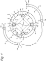
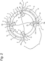
- Figure 1 and 2 show cross sections of a disengaged and engaged bidirectional magnetic clutch 1, respectively, for an additive manufacturing system according to an embodiment of the present invention.
- the bidirectional magnetic clutch comprises a concentric arrangement of an inner drive member 2, e.g. a circular inner drive member 2, and an outer drive member 3, e.g. a circular outer drive member 3, enclosing the inner drive member 2 in the cross section shown, wherein the inner drive member 2 and the outer drive member 3 are rotatable relative to each other.
- the inner drive member 2 comprises at an outer circumferential surface 4 four outward facing recesses 5, 5a, 6, 6a and wherein the outer drive member 3 comprises at an inner circumferential surface 7 four inward facing recesses 8, 8a, 9, 9a.
- an annular gap may be present between the outer circumferential surface 4 and the inner circumferential surface 7 to minimize friction there between and to allow free rotation of the inner and outer drive member 2, 3 with respect to each other.
- Each outward facing recess 5, 5a, 6, 6a comprises a radially moveable roller member 10, 10a, 11, 11a of ferromagnetic material having a diameter which is smaller than an inner receiving depth d1 of the outward facing recess 5, 5a, 6, 6a in which it is received. Further, each inward facing recess 8, 8a, 9, 9a has an outer receiving depth d2 which is smaller than the diameter of each roller member 10, 10a, 11, 11a receivable therein.
- the roller members 10, 10a, 11, 11a may be spherical or cylindrical.
- the inner receiving depth d1 should be construed as a maximum depth associated with each outward facing recess 5, 5a, 6, 6a for receiving a roller member 10, 10a, 11, 11a.
- the diameter a roller member 10, 10a, 11, 11a is smaller than the inner receiving depth d1 implies that the roller member 10, 10a, 11, 11a will not protrude beyond the outer circumferential surface 4 when fully received within its associated outward facing recess 5, 5a, 6, 6a.
- the outer receiving depth d2 should likewise be construed as a maximum depth associated with each inward facing recess 8, 8a, 9, 9a for receiving a roller member 10, 10a, 11, 11a.
- the outer receiving depth d2 is smaller than the diameter of each roller member 10, 10a, 11, 11a implies that a roller member will protrude beyond the inner circumferential surface 7 when fully received within an inward facing recess 8, 8a, 9, 9a.
- each of the recesses 5, 5a, 6, 6a, 8, 8a, 9, 9a may be tapered such that the roller members 10, 10a, 11, 11a may not be able to actually touch a deepest point of the recesses.
- the inner and outer receiving depths d1, d2 must be construed as indicating a maximum depth at which the roller members 10, 10a, 11, 11a can be received within the recesses regardless of the actual geometry thereof.
- the inner drive member 2 is provided with a magnetic biasing system 12 configured to magnetically bias the roller members 10, 10a, 11, 11a into the outward facing recesses 8, 8a, 9, 9a through a biasing magnetic field Fb provided by the magnetic biasing system 12. So, by virtue of the ferromagnetic material of the roller members 10, 11, the magnetic biasing system 12 biases each of the roller members 10, 11 into their respective outward facing recess 5, 5a, 6, 6a through magnetic engagement.
- the bidirectional magnetic clutch may further comprise a magnet actuator 13 at least partially circumferentially arranged around the outer drive member 3 and wherein the magnet actuator 13 is configured to provide/engage an external magnetic field F for maintaining an engaged state of the bidirectional magnetic clutch, see Figure 2 , and in which engaged state the four outward facing recesses 5, 5a, 6, 6a and the four inward facing recesses 8, 8a, 9, 9a are substantially aligned and wherein the roller members 10, 10a, 11, 11a are magnetically attracted into the inward facing recesses 8, 8a, 9, 9a by the external magnetic field F.
- the magnet actuator 13 is further configured to disengage or remove the external magnetic field F for maintaining a disengaged state of the bidirectional magnetic clutch, see Figure 1 , in which the roller members 10, 10a, 11, 11a are magnetically biased (pulled) into the outward facing recesses 5, 5a, 6, 6a by the magnetic biasing system 12.
- each of the roller members 10, 10a, 11, 11a are fully received within their respective outward facing recess 5, 5a, 6, 6a because of the magnetic biasing system 12.
- the outer drive member 3 can rotate freely relative to the inner drive member 2.
- each of the roller members 10, 10a, 11, 11a are partially received in an aligned inward facing recess 8, 9 as well as partially received in their respective outward facing recess 5, 6.
- the magnetic biasing system 12 comprises at least two permanent magnetic roller members.
- the magnetic biasing system 12 is formed by roller members 10, 10a, 11, 11a that magnetically bias themselves into their respective outward facing recess 5, 5a, 6, 6a through the biasing magnetic field Fb provided by the roller members 10, 10a, 11, 11a.
- This embodiment provides a simple design wherein the roller members 10, 10a, 11, 11a exhibit self-biasing behavior through the magnetic engagement there between, so that in the disengaged state of the bidirectional magnetic clutch, the roller members 10, 10a, 11, 11a mutually attract each other into their respective outward facing recess 5, 5a, 6, 6a.
- the magnet actuator 13 provides an external magnetic field F which is sufficiently strong to overcome a biasing force acting on each of the roller members 10, 10a, 11, 11a as provided by the magnetic biasing system 12 and as such the magnet actuator 13 allows the roller members 10, 10a, 11, 11a to be pulled into the inward facing recesses 8, 8a, 9, 9a when the outward and inward facing recesses are aligned.
- Figure 3 and 4 show cross sections of a disengaged and engaged bidirectional magnetic clutch, respectively, according to another embodiment of the present invention.
- the magnetic biasing system 12 may comprises a permanent magnet 14 interposed between the two outward facing recesses 5, 5a, 6, 6a of the inner drive member 2.
- the permanent magnet 14 comprises opposing magnetic poles "N" and "S" each of which faces one of the roller members 10, 10a, 11, 11a.
- the permanent magnet 14 provides the biasing magnetic field Fb for magnetically biasing the roller members 10, 10a, 11, 11a into their respective outward facing recess 5, 5a, 6, 6a to maintain the disengages state of the bidirectional magnetic clutch when the external magnetic field F is removed by the magnet actuator 13.
- roller members 10, 10a, 11, 11a need not be magnetic themselves but by virtue of their ferromagnetic material, the permanent magnets 14, 14a, 14b, 14c interposed between the roller members 10, 10a, 11, 11a ensure that the biasing magnetic field Fb interacts with both roller members 10, 10a, 11, 11a and as such pull the roller members 10, 10a,11, 11a into their respective outward facing recess 5, 5a, 6, 6a.
- the bidirectional magnetic clutch of the present invention may utilize an arbitrary plurality of roller members 10, 11, 10a, 11a and a corresponding plurality of outward facing recesses 5, 5a, 6, 6a and inward facing recesses 8, 8a, 9, 9a.
- the magnetic biasing system 12 may comprise the arbitrary plurality of roller members 10, 11, 10a, 11a wherein each of the roller members 10, 11, 10a, 11a are permanent magnetic roller members 10, 11, 10a, 11a that exhibit self-biasing behaviour through mutually magnetic interaction to remain seated within their respective outward facing recess 5, 6, 5a, 6a when the bidirectional magnetic clutch is in the disengages state.
- the magnetic biasing system 12 may comprise a plurality of permanent magnets 14, 14a, 14b, 14c each of which is interposed between a pair of outward facing recesses 5, 6, 5a, 6a.
- the magnetic biasing system 12 may comprise a plurality of permanent magnets 14, 14a, 14b, 14c each of which is interposed between a pair of outward facing recesses 5, 6, 5a, 6a.
- the magnetic biasing system 12 may comprise a plurality of permanent magnets 14, 14a, 14b, 14c each of which is interposed between a pair of outward facing recesses 5, 6, 5a, 6a.
- each of the permanent magnets 14, 14a, 14b, 14c comprises a north N and south S magnetic pole, and wherein the N and S magnetic poles of the plurality of permanent magnets 14, 14a, 14b, 14c are alternately arranged.
- first permanent magnet 14 interposed between a first pair of outward facing recesses 5, 6, and given a second permeant magnet 14b interposed between a second pair of outward facing recess 5, 5a, then the N magnetic pole of the first permanent magnet 14 faces the S magnetic pole of the second permanent magnet 14a.
- Such an alternating arrangement of magnetic poles N and S allows for a sufficiently strong biasing magnetic field Fb to be provided by the magnetic biasing system 12 for biasing (i.e. attracting) each of the plurality of roller members 10, 11, 10a, 11a into their respective outward facing recesses 5, 6, 5a, 6a.
- the magnetic biasing system 12 may comprise a combination of a plurality of permanent magnet roller members 10, 11, 10a, 11a and a plurality of permanent magnets 14, 14a, 14b, 14c, each of which is interposed between a pair of outward facing recesses 5, 6, 5a, 6a.
- This embodiment would allow for a combination of having magnetic self-biasing behavior of the plurality of roller members 10, 11, 10a, 11a, and magnetic biasing of each of the plurality of roller members 10, 11, 10a, 11a by the plurality of permanent magnets 14, 14a, 14b, 14c, into their respective outward facing recesses 5, 6, 5a, 6a.
- the magnet actuator 13 may comprise a magnetic engagement member 15 which is moveable between a distal radial position relative to the outer drive member 3 and a proximal radial position relative to the outer drive member 3, wherein the external magnetic field F is provided by the permanent magnet engagement member 15 in the proximal radial position for maintaining the engaged state of the bidirectional magnetic clutch 1 and wherein the external magnetic field F is removed by the permanent magnet engagement member 15 in the distal radial position for maintaining the disengaged state of the bidirectional magnetic clutch 1.
- a gap exists between the permanent magnet engagement member 15 and the outer drive member 3, allowing the outer drive member 3 to rotate with respect to the permanent magnet engagement member 15 whilst the bidirectional magnetic clutch is in the engaged state. So, in this embodiment the permanent magnet engagement member 15 does not come into mechanical/physical contact with the outer drive member 3.
- the permanent magnet engagement member 15 may comprise two (or more) permanent magnets 15a, 15b that are positioned such that they engage the two roller members 10, 11 for providing the external magnetic field F.
- each of the two permanent magnets 15a, 15b have a north magnetic pole N and south magnetic pole S, one of which is arranged to face one of the two roller members 10, 11.
- the south magnetic pole S of each permanent magnets 15a, 15b is arranged to face a roller member 10, 11.
- the north magnetic pole N of each permanent magnets 15a, 15b may be arranged to face a roller member 10, 11.
- the permanent magnet engagement member 15 may comprises a curved inner surface 16 conformal to, i.e. shaped in conformal fashion, a curved outer surface 17 of the outer drive member 3.
- the curved inner surface 16 of the permanent magnet engagement member 15 allows snug proximal engagement thereof with the curved outer surface 17 of the outer drive member 3 to maximize field strength of the external magnetic field F for interaction with the two roller members 10, 11 such that the engaged state of the bidirectional magnetic clutch is further ensured when the outward facing recesses 5, 6 and inward facing recesses 8, 9 are aligned.
- the magnet actuator 13 may comprise two magnetic engagement members 15, 18 arranged on opposite sides of the outer drive member 3 and wherein each of the two magnetic engagement members 15, 18 is moveable between a distal radial position and a proximal radial position relative to the outer drive member 3, wherein the external magnetic field F is provided by the two magnetic engagement members 15, 18 in the proximal radial position for maintaining the engaged state of the bidirectional magnetic clutch 1 and wherein the external magnetic field F is removed by the two magnetic engagement members 15, 18 in the distal radial position for maintaining the disengaged state of the bidirectional magnetic clutch.
- each of the two roller members 10, 11 interact with a different permanent magnet engagement member 15, 18 so that a circumferential distribution of the two outward facing recesses 5, 6 and the two roller members 10, 11 received therein can be chosen according to specifications.
- a circumferential distribution of the two outward facing recesses 5, 6 and the two roller members 10, 11 received therein can be chosen according to specifications.
- the two outward facing recesses 5, 6 are arranged on opposite sides of the inner drive member 2, i.e. at 180° degree angle between the two outward facing recesses 5, 6, then having two oppositely arranged magnetic engagement members 15, 18 allows for accurate attraction of each roller member 10, 11 separately in the engages state of the bidirectional magnetic clutch.
- two magnetic engagement members 15, 18 are provided on opposite sides of the outer drive member 3 so that each of the two magnetic engagement members 15, 18 may interact with one or more roller members of the four roller members 10, 11, 10a, 11a as shown, thereby allowing the magnet actuator 13 to magnetically interact with all four roller members 10, 11, 10a, 11a for a given circumferential distribution thereof along the inner drive member 2.
- the magnet actuator 13 may be circumferentially arranged around the outer drive member 3 over 360° degrees to provide an external magnetic field F distributed over 360° degrees as well, e.g. by means of the oppositely arranged two magnetic engagement members 15 covering e.g. 180 ° degrees each.
- Such 360° degree distribution of the external magnetic field F allows effective magnetic interaction with any plurality of roller members 10, 11, 10a, 11a that are circumferentially arranged around the inner drive member 2.
- the actuator may alternatively be arranged only partially circumferentially so as to be able to suitable actuate the roller members.
- each of the two magnetic engagement members 15, 18 comprises a curved inner surface 16, 19 which is conformal to, i.e. shaped in conformal fashion, a curved outer surface 17 of the outer drive member 3.
- both magnetic engagement members 15, 18 allow snug proximal engagement with the curved outer surface 17 of the outer drive member 3 to maximize field strength of the external magnetic field F for interaction with the two roller members 10, 11.
- this embodiment likewise allows snug proximal engagement with the curved outer surface 17 of the outer drive member 3 to maximize field strength of the external magnetic field F for interaction with any plurality of roller members 10, 11, 10a, 11a, e.g. four as depicted, such that the engaged state of the bidirectional magnetic clutch is further ensured when a corresponding plurality of outward facing recesses 5, 6, 5a, 6a and inward facing recesses 8, 9, 8a, 9a are aligned.
- each of the two magnetic engagement members 15, 18 may comprise two (or more) permanent magnets 15a, 15b, 18a, 18b that are positioned such that they can engage the two roller members 10, 11 or any plurality of rollers members 10, 11, 10a, 11a for providing the external magnetic field F.
- Each of the permanent magnets 15a, 15b, 18, 18b have a north magnetic pole N and south magnetic pole S, one of which is arranged to face a roller member 10, 11, 10a, 11.
- the south magnetic pole S of each permanent magnet 15a, 15b, 18a, 18b is arranged to face a roller member 10, 11, 10a, 11a.
- the north magnetic pole N of each permanent magnets 15a, 15b, 18a, 18b may be arranged to face a roller member 10, 11, 10a, 11a.
- FIG. 5 and 6 each of which show a cut away view of a nozzle lifting assembly 50 with the pivotally operated engagement members 15, 18 of the actuator 13 of a disengaged and engaged bidirectional magnetic clutch, respectively, according to an embodiment of the present invention.
- the nozzle lifting assembly 50 comprises a main body 51 which is pivotably arranged around the drive shaft 2.
- the main body 51 comprises a nozzle support arm 52 and a lever arm 53.
- the main body 51 may be formed by a metal plate having the appropriate cutouts as shown in Figure 5 .
- a connection plate 54 is arranged which may comprise a printed circuit board for controlling the nozzle heating and sensing.
- the connection plate 54 is coupled to the frame 51 by means of a bolt 55.
- the connection board 54 may comprise a connector 56 for connection of the board 54 to a power supply or control device (not shown).
- a print core heater 57 is arranged, which may comprise an inductive heating element.
- Figure 5 and 6 also shown a nozzle 58 for depositing print material on a build plate (not shown).
- the nozzle 58 is fixed by way of a nozzle fixing member 59.
- each of the two magnetic engagement members 15, 18 are pivotally arranged around an associated pivot point 15p, 18p.
- the engagement members 15, 18 may be pivotable between a distal angle ⁇ d corresponding to the distal radial position and a proximal angle ⁇ p corresponding to the proximal radial position, thereby allowing for a simple design for moving the oppositely arranged two magnetic engagement members 15, 18 between the distal and proximal radial position with respect to the outer drive member 3.
- both the distal angle ⁇ d and the proximal angle ⁇ p may be measured with respects to a line C at which the oppositely arranged two magnetic engagement members 15, 18 meet in the engaged state of the bidirectional magnetic clutch, see e.g. Figure 6 .
- the two magnetic engagement members 15, 18 may be connected through a geared arrangement 20 configured to synchronously rotate the two magnetic engagement members 15, 18 in opposite rotational directions between the distal angle ⁇ d and proximal angle ⁇ p .
- This geared arrangement ensures that the external magnetic field F applied by the two magnetic engagement members 15, 18 causes substantially equal increase in attraction of all roller members when the two magnetic engagement members 15, 18 move toward the proximal radial position.
- the external magnetic field F exhibits or has associated radially oriented magnetic field lines substantially aligned with the two outward facing recesses 5, 6 and the two inward facing recesses 8, 9 in the engaged state of the bidirectional magnetic clutch, thereby providing for optimized and stronger attraction of each of the roller members 10, 11 into the inward facing recesses 8, 9.
- the magnet actuator 13 need not utilize permanent magnets for providing the external magnetic field F.
- the magnet actuator 13 is an electromagnet actuator configured to electronically provide and remove the external magnetic field F corresponding to the engaged state and disengaged state of the bidirectional magnetic clutch.
- Such an electromagnet actuator may comprise a circumferential arrangement of a plurality of electromagnets around the outer drive member 3 to be activated for attracting the roller members 10, 11, 10a, 11b.
- the two roller members 10, 11 are partially received in corresponding outward facing recesses 5, 6 and inward facing recesses 8, 9 and maintained in such a position as long as the external magnetic field F is applied.
- each of the two roller members 10, 11 comes into contact with the inner and outer drive members 2, 3 and forces are transferred via contact areas between the two roller members 10, 11 and the inner and outer drive members 2, 3.
- each of the outward facing recesses 5, 6 of the inner drive member 2 comprises two opposing concave inner edge surfaces 21 connecting to the outer circumferential surface 4 of the inner drive member 2, and wherein the roller members 10, 11 (not shown) each comprise a convex outer surface which is conformal, i.e. shaped in conformal fashion, to the two concave inner edge surfaces 21.
- each roller member 10, 11 comprises a convex outer surface for engagement in conformal fashion with each concave inner edge surface 21 of the outward facing recess 5, 6 in which it is received.
- the magnet actuator 13 is circumferentially arranged around the outer drive member 3 and configured to provide the external magnetic field F for maintaining an engaged state of the bidirectional magnetic clutch.
- the magnet actuator 13 may comprise two opposing magnetic engagement members 15, 18 or, alternatively, the magnet actuator 13 may be an electromagnet actuator 13.
- the external magnetic field F should exhibit good magnetic interaction with each of the two roller members 10, 11 or any plurality of roller members 10, 11, 10a, 11a.
- the inner and outer drive members 2, 3 are made of a plastic material.
- the low relative magnetic permeability of the plastic material does not interfere with magnetic interaction between the two roller members 10, 11 and the magnet actuator 13 providing the external magnetic field F in the engaged state of the bidirectional magnetic clutch.
- the present invention also relates to an extruder head for an additive manufacturing system utilizing one or more bidirectional magnetic clutches as described above.
- the bidirectional magnetic clutch 1 of the present invention is suited for connecting and disconnecting a filament feeder to orfrom a drive shaft for controlling movement of filament material to or from an extruder nozzle.
- the bidirectional magnetic clutch of the present invention is particularly useful for connecting and disconnected a plurality of filament feeders from a common drive shaft, thereby selecting which filament material is to be fed to or retracted from a particular extruder nozzle of a plurality of extruder nozzles.
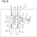
- Figure 8 schematically shows an exemplary embodiment of an extruder head 22 for an additive manufacturing system according to the present invention.
- the extruder head 22 comprises a first extruder nozzle 23a and a first filament feeder 24a provided with a driven first gripper wheel 25a configured for rotation and engaging a first filament material 26a for movement thereof toward or away (e.g. retracted) from the first extruder nozzle 23a.
- the extruder head 22 further comprises with a first bidirectional magnetic clutch 1a of the present invention as described above in light of Figure 1 to 7 and which is connected to the first gripper wheel 25a and a drive shaft 27 of the extruder head 22, and wherein the first bidirectional magnetic clutch 1a is arranged to engage and disengage the first gripper wheel 25a from the drive shaft 27.
- the first bidirectional magnetic clutch 1a of the present invention allows reliable and fast connection and disconnection of the first gripper wheel 25a from the drive shaft 27 through the magnet actuator 13 (not shown).
- the first bidirectional magnetic clutch 1a allows the drive shaft 27 to rotate in opposite directions D1 or D2 such that the first filament material 26a can either be supplied to the first extruder nozzle 23a or retracted therefrom, see the various double arrows in Figure 8 to indicate opposite directions of rotation that are possible.
- the first filament feeder 24a may be provided with a first idler wheel 28a configured for rotation and for pressing the first filament material 26a against the first gripper wheel 25a for improved traction thereof.
- the first gripper wheel 25a is connected to an outer drive member 3a of the first bidirectional magnetic clutch 1a and the drive shaft 27 functions as the inner drive member 2 of the first bidirectional magnetic clutch 1a.
- the first gripper wheel 25a may be connected to the inner drive member 2 of the first bidirectional magnetic clutch 1a and where the drive shaft 27 functions as the outer drive member 3a of the first bidirectional magnetic clutch 1.
- the drive shaft 27 in the engaged state of the first bidirectional magnetic clutch 1a the drive shaft 27 may rotate in both opposite directions D1 or D2 such that the first gripper wheel 25a is rotated in opposite directions for either supplying the first filament material 26a to the first extruder nozzle 23a or retracting the first filament material 26a therefrom.
- the bidirectional magnetic clutch of the present invention is ideally suited for connecting and disconnected a plurality of filament feeders from a drive shaft of an extruder head, thereby providing a convenient magnetic clutch selection arrangement for selecting one or more driven gripper wheels to be driven by a single common drive shaft.
- the extruder head 22 further comprises a second extruder nozzle 23b and a second filament feeder 24b provided with a driven second gripper wheel 25b configured for rotation and engaging a second filament material 26b for movement thereof toward or away from the second extruder nozzle 23b.
- the extruder head 22 further comprises a second bidirectional magnetic clutch 1b of the present invention as described above in light of Figure 1 to 7 .
- the second bidirectional clutch 1b comprises an outer drive member 3b that is connected to the second gripper wheel 25b.
- the second bidirectional magnetic clutch 1b is arranged to engage and disengage the second gripper wheel 25b from the drive shaft 27.
- each of the first and second bidirectional magnetic clutches 1a, 1b may be activated or deactivated accordingly, thereby connecting or disconnecting the first and second gripper wheels 25a, 25b from the drive shaft 27 in corresponding fashion.
- first and second bidirectional magnetic clutches 1a, 1b may be engaged simultaneously, so that the drive shaft 27 drives both the first and second gripping wheels 25a, 25b simultaneously for dispensing both the first and second filament material 26a, 26b simultaneously.
- the second filament feeder 24b may be provided with a second idler wheel 28b configured for rotation and for pressing the second filament material 26b against the second gripper wheel 25b for improved traction thereof.
- the extruder head 22 of the present invention readily allows for an arbitrary plurality of filament feeders 24a, 24b to be connected or disconnected from a single common drive shaft 27 of the extruder head 22.
- each of the plurality of bidirectional magnetic clutches 1a, 1b allows for opposite rotations D1, D2 of the drive shaft 27, it is possible to conveniently and quickly select which of the plurality of filament materials 26a, 26b is supplied to or retracted from one of the plurality of extruder nozzles 23a, 23b.
- the extruder head 22 of the present invention exhibits a simpler design and can be made very compact as the plurality of bidirectional magnetic clutches 1a, 1b can be arranged in a snug side-by-side arrangement along the drive shaft 27.
- Figure 9 shows a perspective view of part of an extruder head 22 according to an embodiment of the invention.
- the extruder head 22 is also referred to as printer head 22.
- an outer housing of the extruder head 22 is removed so as to show some of the interior of the extruder head 22.
- the extruder head 22 in this embodiment comprises four nozzle lifting assemblies each having a print nozzle 91, 92, 93 and 94, and associated filament inlets 95, 96, 97 and 98.
- the extruder head 22 in this embodiment further comprises a printer head frame comprising a first guiding cylinder 101 and a second guiding cylinder 102 for cooperation with rods of a gantry (not shown). Furthermore, the extruder head 22 comprises a motor 105 arranged to rotate a drive shaft 27, see also Figure 10 , which extends through the four nozzle lifting assemblies. As can be seen from Figure 9 , one of the nozzles, i.e. the fourth nozzle 94, has been lowered while the three others have been lifted.
- Figure 10 shows a cut away view of the extruder head of Figure 9 also now showing a housing 80 of the extruder head 22.
- the nozzle lifting assemblies each comprise a lever arm 81, 82.
- the lever arms 81, 82 can be manipulated using an activation mechanism (not shown) so as to rotate the nozzle lifting assemblies around the drive shaft 27.
- a filament feeder 86 is shown which is arranged to feed filament coming through inlet 98 to the nozzle 94.
- Figure 10 also shows the two magnetic engagement members 15, 18 of the actuator.
- the engagement members 15, 18 are pivotably arranged on a main body of the lifting assembly as was explained above with reference to Figure 5 and 6 .
- the print head 22 comprises a plurality of gear plates 84 each comprising teeth 85.
- the number of gear plates 84 resembles the number of nozzle lifting assemblies. So if the print head 22 comprises four lifting assemblies, the number of gear plates will be four.
- the gear plates 84 are fixed relative to the print head 22. As can be seen from Figure 10 , some of the teeth of the geared arrangement 20 interact with teeth 85 of the gear plate 84. When pressing down the lever arm 82 from an upper state to a lower state, the corresponding lifting assembly will be rotated around the drive shaft 27.
Landscapes
- Engineering & Computer Science (AREA)
- General Engineering & Computer Science (AREA)
- Mechanical Engineering (AREA)
- Chemical & Material Sciences (AREA)
- Materials Engineering (AREA)
- Physics & Mathematics (AREA)
- Manufacturing & Machinery (AREA)
- Electromagnetism (AREA)
- Optics & Photonics (AREA)
- Dynamo-Electric Clutches, Dynamo-Electric Brakes (AREA)
- Transmission Devices (AREA)
Description
- The present invention relates to a magnetic clutch for an additive manufacturing system, in particular a bidirectional magnetic clutch for an additive manufacturing system. In a further aspect the present invention relates to an extruder head for an additive manufacturing system comprising such a bidirectional magnetic clutch.
- US patent publication
US 9,816,571 B1 - The aforementioned bidirectional coupler requires that the inner shaft must have a non-zero rotational speed to dislocate the ball bearing toward the outer ring and as such prevent relative rotation between the inner and outer ring. However, when the inner shaft rotates and the ball bearing moves outwards, at some point both rings lock rather abruptly with a shock as the ball bearing suddenly engages the end portions of the slots.
- Further, document
CN 202 040 233 U discloses a bidirectional magnetic clutch according to the preamble of claim 1. - The present invention aims to provide a magnetic clutch, particularly a two-way magnetic clutch or bidirectional magnetic clutch for an additive manufacturing system, allowing a drive and driven member to be coupled more smoothly and in substantially stationary fashion. A plurality of bidirectional magnetic clutches of the present invention can be utilized for obtaining a convenient magnetic clutch selection arrangement for selecting one or more feeders to be driven by a single drive shaft.
- According to the present invention, as defined in claim 1, a bidirectional magnetic clutch is provided comprising, a concentric arrangement of an inner drive member and an outer drive member enclosing the inner drive member, wherein the inner drive member and the outer drive member are rotatable relative to each other.
- The inner drive member comprises at an outer circumferential surface at least two outward facing recesses and the outer drive member comprises at an inner circumferential surface at least two inward facing recesses. Each outward facing recess comprises a radially moveable roller member of ferromagnetic material and having a diameter which is smaller than a depth, i.e. an inner receiving depth, of the outward facing recess in which it is received, and wherein each inward facing recess has a depth, i.e. an outer receiving depth, which is smaller than the diameter of each roller member.
- The inner drive member is further provided with a magnetic biasing system configured to magnetically bias the roller members into the outward facing recesses through a biasing magnetic field.
- The bidirectional magnetic clutch further comprises a magnet actuator which is at least partially circumferentially arranged around the outer drive member and configured to provide an external magnetic field for maintaining an engaged state of the bidirectional magnetic clutch in which the at least two outward facing recesses and the at least two inward facing recesses are substantially aligned and the roller members are magnetically attracted into the inward facing recesses by the external magnetic field, and
wherein the magnet actuator is further configured to remove the external magnetic field for maintaining a disengaged state of the bidirectional magnetic clutch in which the roller members are magnetically biased into, e.g. fully into, the outward facing recesses by the magnetic biasing system. - According to the present invention, in the disengaged state of the bidirectional magnetic clutch, each of the roller members are fully received within their respective outward facing recess and as such the inner and outer drive member can rotate relative to one another. In the engaged state of the bidirectional magnetic clutch, each of the roller members are partially received within the inward facing recesses as well as in the outward facing recess, thereby blocking relative rotation between the inner and outer drive members. As such, the bidirectional magnetic clutch is able to allow torque transfer in two rotational directions, i.e. in clockwise and counter clockwise direction.
- In an embodiment, the magnetic biasing system comprises one of or more of the roller members, wherein the one or more of the roller members are permanent magnetic roller members. In this embodiment the roller members are magnetically biased into their respective outward facing recess through a biasing magnetic field provided by the magnetic roller members and as such through magnetic interaction between the roller members. Different embodies are conceivable, for example one roller member being a permanent magnet attracting one or more other roller ferromagnetic members, or several roller members each being permanent magnets attracting each other.
- In another embodiment, the magnetic biasing system comprises a permanent magnet arranged in the inner drive member and which permanent magnet is interposed between two of the at least two outward facing recesses. In this embodiment, two roller members are magnetically biased into their respective outward facing recess through magnetic interaction with the permanent magnet.
- In a further aspect, the present invention relates to an extruder head for an additive manufacturing system utilizing the above-mentioned bidirectional magnetic clutch of the present invention. The extruder head comprises a first extruder nozzle, a drive shaft and a first filament feeder provided with a driven first gripper wheel configured for rotation and engaging a first filament material for movement thereof toward or away from the first extruder nozzle, wherein the extruder head further comprises a first bidirectional magnetic clutch as described above, i.e. in accordance with the invention, wherein the first bidirectional magnetic clutch is arranged to engage and disengage the first gripper wheel from the drive shaft.
- The bidirectional magnetic clutch of the present invention is ideally suited for use in an extruder head of an additive manufacturing system, wherein the first filament feeder can be connected to or disconnected from the drive shaft in a reliable and efficient manner for controlling movement of the first filament material to or from the first extruder nozzle.
- In an embodiment, the extruder head further comprises a second extruder nozzle and a second filament feeder provided with a driven second gripper wheel configured for rotation and engaging a second filament material for movement thereof toward or away from the second extruder nozzle, wherein the extruder head further comprises a second bidirectional magnetic clutch as described above, i.e. in accordance with the invention, wherein the second bidirectional magnetic clutch is arranged to engage and disengage the second gripper wheel from the drive shaft.
- The extruder head of the present invention is particularly advantageous as it readily allows for an arbitrary plurality of filament feeders to be connected to and disconnected from a single common drive shaft of the extruder head. Moreover, because each of the plurality of bidirectional magnetic clutches of the extruded head allows for opposite rotations of the drive shaft, it is possible to conveniently and quickly select which filament material of a plurality of filament materials is supplied to or retracted from one of the plurality of extruder nozzles. As a result, the extruder head of the present invention provides a simple yet effective design and can be made compact as the plurality of bidirectional magnetic clutches can be arranged in a snug side-by-side arrangement along the drive shaft of the extruder head.
- The present invention will now be described by way of reference to a number of illustrative embodiments as shown in the accompanying drawings in which:
-
Figure 1 shows a cross section of a disengaged bidirectional magnetic clutch according to an embodiment of the present invention; -
Figure 2 shows a cross section of an engaged bidirectional magnetic clutch according to an embodiment of the present invention; -
Figure 3 shows a cross section of a disengaged bidirectional magnetic clutch according to another embodiment of the present invention; -
Figure 4 shows a cross section of an engaged bidirectional magnetic clutch according to another embodiment of the present invention; -
Figure 5 shows a cut away view of a nozzle lifting assembly with a pivotally operated magnet actuator of a disengaged bidirectional magnetic clutch according to an embodiment of the present invention; -
Figure 6 shows a cut away view of a nozzle lifting assembly with a pivotally operated magnet actuator of an engaged bidirectional clutch according to an embodiment of the present invention; -
Figure 7 shows a detailed view of a part ofFigure 6 ; -
Figure 8 schematically shows an embodiment of an extruder head for an additive manufacturing system according to an embodiment of the present invention; -
Figure 9 shows a perspective view of part of an extruder head according to an embodiment of the invention, and -
Figure 10 shows a cut away view of the extruder head ofFigure 9 . -
Figure 1 and2 show cross sections of a disengaged and engaged bidirectional magnetic clutch 1, respectively, for an additive manufacturing system according to an embodiment of the present invention. In the embodiment shown, the bidirectional magnetic clutch comprises a concentric arrangement of aninner drive member 2, e.g. a circularinner drive member 2, and anouter drive member 3, e.g. a circularouter drive member 3, enclosing theinner drive member 2 in the cross section shown, wherein theinner drive member 2 and theouter drive member 3 are rotatable relative to each other. - The
inner drive member 2 comprises at an outercircumferential surface 4 four outward facingrecesses outer drive member 3 comprises at an innercircumferential surface 7 four inward facingrecesses circumferential surface 4 and the innercircumferential surface 7 to minimize friction there between and to allow free rotation of the inner andouter drive member - Each outward facing
recess moveable roller member recess recess roller member roller members - The inner receiving depth d1 should be construed as a maximum depth associated with each outward facing
recess roller member roller member roller member circumferential surface 4 when fully received within its associated outward facingrecess - The outer receiving depth d2 should likewise be construed as a maximum depth associated with each inward facing
recess roller member roller member circumferential surface 7 when fully received within an inward facingrecess - It should be noted that the outward facing
recesses recesses Figures 1 and2 , each of therecesses roller members roller members - A further shown in
Figure 1 , theinner drive member 2 is provided with amagnetic biasing system 12 configured to magnetically bias theroller members recesses magnetic biasing system 12. So, by virtue of the ferromagnetic material of theroller members magnetic biasing system 12 biases each of theroller members recess - The bidirectional magnetic clutch may further comprise a
magnet actuator 13 at least partially circumferentially arranged around theouter drive member 3 and wherein themagnet actuator 13 is configured to provide/engage an external magnetic field F for maintaining an engaged state of the bidirectional magnetic clutch, seeFigure 2 , and in which engaged state the four outward facingrecesses recesses roller members recesses magnet actuator 13 is further configured to disengage or remove the external magnetic field F for maintaining a disengaged state of the bidirectional magnetic clutch, seeFigure 1 , in which theroller members recesses magnetic biasing system 12. - According to the present invention, in the disengaged state of the bidirectional magnetic clutch 1 as shown in
Figure 1 , each of theroller members recess magnetic biasing system 12. As a result, theouter drive member 3 can rotate freely relative to theinner drive member 2. In the engaged state of the bidirectional magnetic clutch as shown inFigure 2 , each of theroller members recess recess roller members recess - In an advantageous embodiment the
magnetic biasing system 12 comprises at least two permanent magnetic roller members. In this embodiment, themagnetic biasing system 12 is formed byroller members recess roller members roller members roller members recess - Note that when the bidirectional magnetic clutch is in the engaged state shown in
Figure 2 , then themagnet actuator 13 provides an external magnetic field F which is sufficiently strong to overcome a biasing force acting on each of theroller members magnetic biasing system 12 and as such themagnet actuator 13 allows theroller members -
Figure 3 and4 show cross sections of a disengaged and engaged bidirectional magnetic clutch, respectively, according to another embodiment of the present invention. In the embodiments shown, themagnetic biasing system 12 may comprises apermanent magnet 14 interposed between the two outward facingrecesses inner drive member 2. In this embodiment thepermanent magnet 14 comprises opposing magnetic poles "N" and "S" each of which faces one of theroller members permanent magnet 14 provides the biasing magnetic field Fb for magnetically biasing theroller members recess magnet actuator 13. Note that in this embodiment the fourroller members permanent magnets roller members roller members roller members recess - It is important to note that from
Figures 1 to 4 it is clear that the bidirectional magnetic clutch of the present invention may utilize an arbitrary plurality ofroller members - In an exemplary embodiment, as shown in
Figure 1 and2 , for an arbitrary plurality ofroller members magnetic biasing system 12 may comprise the arbitrary plurality ofroller members roller members magnetic roller members recess - In a further exemplary embodiment, as shown in
Figure 3 and4 , for an arbitrary plurality ofroller members magnetic biasing system 12 may comprise a plurality ofpermanent magnets permanent magnets magnetic biasing system 12 and wherein each of the fourpermanent magnets - As depicted in
Figure 3 and4 , for a plurality ofpermanent magnets magnetic biasing system 12, in an embodiment each of thepermanent magnets permanent magnets permanent magnet 14 interposed between a first pair of outward facing recesses 5, 6, and given a secondpermeant magnet 14b interposed between a second pair of outward facingrecess permanent magnet 14 faces the S magnetic pole of the secondpermanent magnet 14a. Such an alternating arrangement of magnetic poles N and S allows for a sufficiently strong biasing magnetic field Fb to be provided by themagnetic biasing system 12 for biasing (i.e. attracting) each of the plurality ofroller members recesses - Note that in an embodiment it is conceivable that the
magnetic biasing system 12 may comprise a combination of a plurality of permanentmagnet roller members permanent magnets roller members roller members permanent magnets recesses - With reference to the
Figures 1 to 4 , in an embodiment themagnet actuator 13 may comprise amagnetic engagement member 15 which is moveable between a distal radial position relative to theouter drive member 3 and a proximal radial position relative to theouter drive member 3, wherein the external magnetic field F is provided by the permanentmagnet engagement member 15 in the proximal radial position for maintaining the engaged state of the bidirectional magnetic clutch 1 and wherein the external magnetic field F is removed by the permanentmagnet engagement member 15 in the distal radial position for maintaining the disengaged state of the bidirectional magnetic clutch 1. In an embodiment, in the proximal radial position a gap exists between the permanentmagnet engagement member 15 and theouter drive member 3, allowing theouter drive member 3 to rotate with respect to the permanentmagnet engagement member 15 whilst the bidirectional magnetic clutch is in the engaged state. So, in this embodiment the permanentmagnet engagement member 15 does not come into mechanical/physical contact with theouter drive member 3. - In this embodiment, by simply moving the permanent
magnet engagement member 15 toward theouter drive member 3 to the proximal radial position allows the bidirectional magnetic clutch to be in the engaged state as the external magnetic field F will interact with the tworoller members roller members inward facing recess recess roller members outer drive members roller members recess inward facing recess - Conversely, by simply moving the permanent
magnet engagement member 15 away from theinner drive member 3 toward the distal radial position allows the bidirectional magnetic clutch to be in the disengaged state as each of the tworoller members recess magnetic biasing system 12. - In an embodiment, the permanent
magnet engagement member 15 may comprise two (or more)permanent magnets roller members permanent magnets roller members permanent magnets roller member permanent magnets roller member - As further depicted in the
Figures 1 to 4 , in an embodiment the permanentmagnet engagement member 15 may comprises a curvedinner surface 16 conformal to, i.e. shaped in conformal fashion, a curvedouter surface 17 of theouter drive member 3. In this embodiment the curvedinner surface 16 of the permanentmagnet engagement member 15 allows snug proximal engagement thereof with the curvedouter surface 17 of theouter drive member 3 to maximize field strength of the external magnetic field F for interaction with the tworoller members - In an embodiment, the
magnet actuator 13 may comprise twomagnetic engagement members outer drive member 3 and wherein each of the twomagnetic engagement members outer drive member 3, wherein the external magnetic field F is provided by the twomagnetic engagement members magnetic engagement members - In this embodiment it is possible that each of the two
roller members magnet engagement member recesses roller members recesses inner drive member 2, i.e. at 180° degree angle between the two outward facingrecesses magnetic engagement members roller member - Having two oppositely arranged
magnetic engagement members roller members magnetic engagement members outer drive member 3 so that each of the twomagnetic engagement members roller members magnet actuator 13 to magnetically interact with all fourroller members inner drive member 2. - From the above it is clear that in a general embodiment the
magnet actuator 13 may be circumferentially arranged around theouter drive member 3 over 360° degrees to provide an external magnetic field F distributed over 360° degrees as well, e.g. by means of the oppositely arranged twomagnetic engagement members 15 covering e.g. 180 ° degrees each. Such 360° degree distribution of the external magnetic field F allows effective magnetic interaction with any plurality ofroller members inner drive member 2. However it is noted that the actuator may alternatively be arranged only partially circumferentially so as to be able to suitable actuate the roller members. - In an embodiment, each of the two
magnetic engagement members inner surface outer surface 17 of theouter drive member 3. In this embodiment bothmagnetic engagement members outer surface 17 of theouter drive member 3 to maximize field strength of the external magnetic field F for interaction with the tworoller members outer surface 17 of theouter drive member 3 to maximize field strength of the external magnetic field F for interaction with any plurality ofroller members - In an embodiment, each of the two
magnetic engagement members permanent magnets roller members rollers members permanent magnets roller member permanent magnet roller member permanent magnets roller member - Turning to
Figure 5 and 6 , each of which show a cut away view of anozzle lifting assembly 50 with the pivotally operatedengagement members actuator 13 of a disengaged and engaged bidirectional magnetic clutch, respectively, according to an embodiment of the present invention. - In this embodiment, the
nozzle lifting assembly 50 comprises amain body 51 which is pivotably arranged around thedrive shaft 2. Themain body 51 comprises anozzle support arm 52 and alever arm 53. Themain body 51 may be formed by a metal plate having the appropriate cutouts as shown inFigure 5 . At a bottom side of themain body 51, aconnection plate 54 is arranged which may comprise a printed circuit board for controlling the nozzle heating and sensing. Theconnection plate 54 is coupled to theframe 51 by means of abolt 55. Theconnection board 54 may comprise aconnector 56 for connection of theboard 54 to a power supply or control device (not shown). Below theconnection plate 54, aprint core heater 57 is arranged, which may comprise an inductive heating element.Figure 5 and 6 also shown anozzle 58 for depositing print material on a build plate (not shown). Thenozzle 58 is fixed by way of anozzle fixing member 59. - In the embodiment shown in
Figures 5 and 6 , each of the twomagnetic engagement members pivot point engagement members magnetic engagement members outer drive member 3. Note that in this embodiment, both the distal angle αd and the proximal angle αp may be measured with respects to a line C at which the oppositely arranged twomagnetic engagement members Figure 6 . - As further shown, in an embodiment the two
magnetic engagement members arrangement 20 configured to synchronously rotate the twomagnetic engagement members magnetic engagement members magnetic engagement members - Referring back to the
Figures 1 to 4 , in a general embodiment the external magnetic field F exhibits or has associated radially oriented magnetic field lines substantially aligned with the two outward facingrecesses roller members - Note that the
magnet actuator 13 need not utilize permanent magnets for providing the external magnetic field F. For example, in an alternative embodiment themagnet actuator 13 is an electromagnet actuator configured to electronically provide and remove the external magnetic field F corresponding to the engaged state and disengaged state of the bidirectional magnetic clutch. Such an electromagnet actuator may comprise a circumferential arrangement of a plurality of electromagnets around theouter drive member 3 to be activated for attracting theroller members - As mentioned above, when the bidirectional magnetic clutch is in an engaged state, the two
roller members recesses outer drive members roller members outer drive members roller members outer drive members -
Figure 7 shows a detailed view of a part ofFigure 6 . In the embodiment shown, each of the outward facing recesses 5, 6 of theinner drive member 2 comprises two opposing concave inner edge surfaces 21 connecting to the outercircumferential surface 4 of theinner drive member 2, and wherein theroller members 10, 11 (not shown) each comprise a convex outer surface which is conformal, i.e. shaped in conformal fashion, to the two concave inner edge surfaces 21. In this embodiment, eachroller member inner edge surface 21 of the outward facingrecess roller members inner drive member 2 is achieved and as such an improved force distribution is obtained when torque is transmitted between the inner andouter drive member - According to the present invention, the
magnet actuator 13 is circumferentially arranged around theouter drive member 3 and configured to provide the external magnetic field F for maintaining an engaged state of the bidirectional magnetic clutch. As described above, themagnet actuator 13 may comprise two opposingmagnetic engagement members magnet actuator 13 may be anelectromagnet actuator 13. In either case, the external magnetic field F should exhibit good magnetic interaction with each of the tworoller members roller members - To ensure that good magnetic interaction is provided between the
magnet actuator 13 and the tworoller members roller members outer drive members roller members magnet actuator 13 providing the external magnetic field F in the engaged state of the bidirectional magnetic clutch. - In a further aspect, the present invention also relates to an extruder head for an additive manufacturing system utilizing one or more bidirectional magnetic clutches as described above. In particular, the bidirectional magnetic clutch 1 of the present invention is suited for connecting and disconnecting a filament feeder to orfrom a drive shaft for controlling movement of filament material to or from an extruder nozzle. The bidirectional magnetic clutch of the present invention is particularly useful for connecting and disconnected a plurality of filament feeders from a common drive shaft, thereby selecting which filament material is to be fed to or retracted from a particular extruder nozzle of a plurality of extruder nozzles.
- In view of the above,
Figure 8 schematically shows an exemplary embodiment of anextruder head 22 for an additive manufacturing system according to the present invention. In the embodiment shown, theextruder head 22 comprises afirst extruder nozzle 23a and a first filament feeder 24a provided with a drivenfirst gripper wheel 25a configured for rotation and engaging afirst filament material 26a for movement thereof toward or away (e.g. retracted) from thefirst extruder nozzle 23a. Theextruder head 22 further comprises with a first bidirectional magnetic clutch 1a of the present invention as described above in light ofFigure 1 to 7 and which is connected to thefirst gripper wheel 25a and adrive shaft 27 of theextruder head 22, and wherein the first bidirectional magnetic clutch 1a is arranged to engage and disengage thefirst gripper wheel 25a from thedrive shaft 27. In this embodiment, the first bidirectional magnetic clutch 1a of the present invention allows reliable and fast connection and disconnection of thefirst gripper wheel 25a from thedrive shaft 27 through the magnet actuator 13 (not shown). Moreover, the first bidirectional magnetic clutch 1a allows thedrive shaft 27 to rotate in opposite directions D1 or D2 such that thefirst filament material 26a can either be supplied to thefirst extruder nozzle 23a or retracted therefrom, see the various double arrows inFigure 8 to indicate opposite directions of rotation that are possible. In an embodiment, the first filament feeder 24a may be provided with afirst idler wheel 28a configured for rotation and for pressing thefirst filament material 26a against thefirst gripper wheel 25a for improved traction thereof. - In the embodiment of
Figure 8 , thefirst gripper wheel 25a is connected to an outer drive member 3a of the first bidirectional magnetic clutch 1a and thedrive shaft 27 functions as theinner drive member 2 of the first bidirectional magnetic clutch 1a. In an alternative embodiment thefirst gripper wheel 25a may be connected to theinner drive member 2 of the first bidirectional magnetic clutch 1a and where thedrive shaft 27 functions as the outer drive member 3a of the first bidirectional magnetic clutch 1. In either embodiment, in the engaged state of the first bidirectional magnetic clutch 1a thedrive shaft 27 may rotate in both opposite directions D1 or D2 such that thefirst gripper wheel 25a is rotated in opposite directions for either supplying thefirst filament material 26a to thefirst extruder nozzle 23a or retracting thefirst filament material 26a therefrom. - The bidirectional magnetic clutch of the present invention is ideally suited for connecting and disconnected a plurality of filament feeders from a drive shaft of an extruder head, thereby providing a convenient magnetic clutch selection arrangement for selecting one or more driven gripper wheels to be driven by a single common drive shaft.
- For example, in the embodiment of
Figure 8 , theextruder head 22 further comprises asecond extruder nozzle 23b and a second filament feeder 24b provided with a drivensecond gripper wheel 25b configured for rotation and engaging asecond filament material 26b for movement thereof toward or away from thesecond extruder nozzle 23b. Theextruder head 22 further comprises a second bidirectional magnetic clutch 1b of the present invention as described above in light ofFigure 1 to 7 . The second bidirectional clutch 1b comprises anouter drive member 3b that is connected to thesecond gripper wheel 25b. The second bidirectional magnetic clutch 1b is arranged to engage and disengage thesecond gripper wheel 25b from thedrive shaft 27. - In this embodiment it is possible to select whether the first or
second filament material second extruder nozzle Figure 8 ) of each of the first and second bidirectionalmagnetic clutches second gripper wheels drive shaft 27 in corresponding fashion. - Note that in an embodiment it is conceivable that the first and second bidirectional
magnetic clutches drive shaft 27 drives both the first and secondgripping wheels second filament material - In an embodiment, the second filament feeder 24b may be provided with a
second idler wheel 28b configured for rotation and for pressing thesecond filament material 26b against thesecond gripper wheel 25b for improved traction thereof. - From the above it can be seen that the
extruder head 22 of the present invention readily allows for an arbitrary plurality of filament feeders 24a, 24b to be connected or disconnected from a singlecommon drive shaft 27 of theextruder head 22. Moreover, as each of the plurality of bidirectionalmagnetic clutches drive shaft 27, it is possible to conveniently and quickly select which of the plurality offilament materials extruder nozzles extruder head 22 of the present invention exhibits a simpler design and can be made very compact as the plurality of bidirectionalmagnetic clutches drive shaft 27. -
Figure 9 shows a perspective view of part of anextruder head 22 according to an embodiment of the invention. Theextruder head 22 is also referred to asprinter head 22. InFigure 9 an outer housing of theextruder head 22 is removed so as to show some of the interior of theextruder head 22. Theextruder head 22 in this embodiment comprises four nozzle lifting assemblies each having aprint nozzle filament inlets - The
extruder head 22 in this embodiment further comprises a printer head frame comprising afirst guiding cylinder 101 and asecond guiding cylinder 102 for cooperation with rods of a gantry (not shown). Furthermore, theextruder head 22 comprises amotor 105 arranged to rotate adrive shaft 27, see alsoFigure 10 , which extends through the four nozzle lifting assemblies. As can be seen fromFigure 9 , one of the nozzles, i.e. thefourth nozzle 94, has been lowered while the three others have been lifted. -
Figure 10 shows a cut away view of the extruder head ofFigure 9 also now showing ahousing 80 of theextruder head 22. InFigure 10 only parts of two nozzle lifting assemblies are visible, i.e. the ones lifting thenozzles lever arm lever arms drive shaft 27. In the cut out view afilament feeder 86 is shown which is arranged to feed filament coming throughinlet 98 to thenozzle 94.Figure 10 also shows the twomagnetic engagement members engagement members Figure 5 and 6 . In this embodiment, theprint head 22 comprises a plurality ofgear plates 84 each comprisingteeth 85. The number ofgear plates 84 resembles the number of nozzle lifting assemblies. So if theprint head 22 comprises four lifting assemblies, the number of gear plates will be four. Thegear plates 84 are fixed relative to theprint head 22. As can be seen fromFigure 10 , some of the teeth of the gearedarrangement 20 interact withteeth 85 of thegear plate 84. When pressing down thelever arm 82 from an upper state to a lower state, the corresponding lifting assembly will be rotated around thedrive shaft 27. Due to the interaction of the gearedarrangement 20 with theteeth 85 of thegear plate 84, thelower engagement member 15 will rotate relative to the main body of the lifting assembly. As a consequence, also the other engagement member, i.e.engagement member 18, will rotate, and as a result, the twoengagement members Figure 5 . Similarly, when lifting thelever arm 82 from the lower state to the upper state, the opposite occurs and theengagement members - As a result of the above described mechanism, a feeder of a lifted nozzle gets deactivated while a feeder of a lowered nozzle gets activated. So, by manipulation of the
lever arms nozzles feeders 86 are properly activated or deactivated. - In the situation shown in
Figure 10 , themagnetic engagement members Figure 6 . Now the associated clutch is in the disengaged state and a rotation of thedrive shaft 27 is not transferred to the gears (not shown inFigure 10 ) of thefeeder 86, meaning that thefeeder 86 is deactivated. - The present invention has been described above with reference to a number of exemplary embodiments as shown in the drawings. Modifications and alternative implementations of some parts or elements are possible, as far as they remain within the scope of protection as defined in the appended claims.
Claims (15)
- A bidirectional magnetic clutch for an additive manufacturing system, comprising a concentric arrangement of an inner drive member (2) and an outer drive member (3) enclosing the inner drive member (2), the inner drive member (2) and the outer drive member (3) being rotatable relative to each other,wherein the inner drive member (2) comprises at an outer circumferential surface (4) at least two outward facing recesses (5,6), and wherein the outer drive member (3) comprises at an inner circumferential surface (7) at least two inward facing recesses (8, 9),wherein each outward facing recess (5,6) comprises a radially moveable roller member (10,11) of ferromagnetic material and having a diameter which is smaller than an inner receiving depth (d1) of the outward facing recess (5,6) in which it is received, and wherein each inward facing recess (8,9) has an outer receiving depth (d2) which is smaller than the diameter of each roller member (10,11),wherein the inner drive member (2) is further provided with a magnetic biasing system (12) configured to magnetically bias the roller members (10,11) into the outward facing recesses (5, 6) through a biasing magnetic field (Fb), characterized in that the bidirectional magnetic clutch (1) further comprises:a magnet actuator (13) at least partially circumferentially arranged around the outer drive member (3) and configured to provide an external magnetic field (F) for maintaining an engaged state of the bidirectional magnetic clutch in which the at least two outward facing recesses (5,6) and the at least two inward facing recesses (8,9) are substantially aligned and the roller members (10,11) are magnetically attracted into the inward facing recesses (8,9) by the external magnetic field (F), andin that the magnet actuator (13) is further configured to remove the external magnetic field (F) for maintaining a disengaged state of the bidirectional magnetic clutch (1) in which the roller members (10,11) are magnetically biased into the outward facing recesses (5,6) by the magnetic biasing system (12).
- The bidirectional magnetic clutch according to claim 1, wherein the magnetic biasing system (12) comprises one or more of the roller members (10,11), wherein the one or more of the roller members (10,11) are permanent magnetic roller members.
- The bidirectional magnetic clutch according to claim 1 or 2, wherein the magnetic biasing system (12) comprises a permanent magnet (14) arranged in the inner drive member (2) and interposed between two of the at least two outward facing recesses (5,6).
- The bidirectional magnetic clutch according to any one of claims 1-3, wherein the magnet actuator (13) comprises a magnetic engagement member (15) moveable between a distal radial position and a proximal radial position relative to the outer drive member (3),
wherein the external magnetic field (F) is provided by the magnetic engagement member (15) in the proximal radial position for maintaining the engaged state of the bidirectional magnetic clutch and wherein the external magnetic field (F) is removed by the magnetic engagement member (15) in the distal radial position for maintaining the disengaged state of the bidirectional magnetic clutch (1). - The bidirectional magnetic clutch according to claim 4, wherein the magnetic engagement member (15) comprises a curved inner surface (16) shaped in conformal fashion to a curved outer surface (17) of the outer drive member (3).
- The bidirectional magnetic clutch according to any one of claims 1-4, wherein the magnet actuator (13) comprises two magnetic engagement members (15,18) arranged on opposite sides of the outer drive member (3) and wherein each of the two magnetic engagement members (15,18) is moveable between a distal radial position and a proximal radial position relative to the outer drive member (3),
wherein the external magnetic field (F) is provided by the two magnetic engagement members (15,18) in the proximal radial position for maintaining the engaged state of the bidirectional magnetic clutch and wherein the external magnetic field (F) is removed by the two magnetic engagement members (15,18) in the distal radial position for maintaining the disengaged state of the bidirectional magnetic clutch. - The bidirectional magnetic clutch according to claim 6, wherein each of the two magnetic engagement members (15,18) comprises a curved inner surface (16,19) shaped in conformal fashion to a curved outer surface (17) of the outer drive member (3).
- The bidirectional magnetic clutch according to claim 6 or 7, wherein each of the two magnetic engagement members (15,18) are pivotally arranged between a distal angle (αd) corresponding to the distal radial position and a proximal angle (αp) corresponding to the proximal radial position.
- The bidirectional magnetic clutch according to claim 8, wherein the two magnetic engagement members (15,18) are connected through a geared arrangement (20) configured to synchronously rotate the two magnetic engagement members (15,18) in opposite rotational directions between the distal angle (αd) and proximal angle (αp).
- The bidirectional magnetic clutch according to any one of claims 1-9, wherein the external magnetic field (F) has associated radially oriented magnetic field lines substantially aligned with the outward facing recesses (5,6) and the inward facing recesses (8,9) in the engaged state of the bidirectional magnetic clutch (1).
- The bidirectional magnetic clutch according to any of claims 1-3, wherein the magnet actuator (13) is an electromagnet actuator configured to electronically engage and disengage the external magnetic field (F) corresponding to the engaged state and disengaged state of the bidirectional magnetic clutch (1) respectively.
- The bidirectional magnetic clutch according to any one of claims 1-11, wherein each of the at least two outward facing recesses (5,6) of the inner drive member (2) comprises two opposing concave inner edge surfaces (21) connecting to the outer circumferential surface (4) of the inner drive member (2), and wherein the roller members (10,11) each comprise a convex outer surface which is shaped in conformal fashion to the two concave inner edge surfaces (21).
- The bidirectional magnetic clutch according to any one of claims 1-12, wherein the inner drive member (2) and the outer drive member (3) are made of a plastic material.
- An extruder head (22) for an additive manufacturing system, comprises a first extruder nozzle (23a; 93), a drive shaft (27) and a first filament feeder (24a; 86) provided with a driven first gripper wheel (25a) configured for rotation and engaging a first filament material (26a) for movement thereof toward or away from the first extruder nozzle (23a; 93), wherein the extruder head (22) further comprises
a first bidirectional magnetic clutch (1a) according to any of claims 1-13, wherein the first bidirectional magnetic clutch (1a) is arranged to engage and disengage the first gripper wheel (25a) from the drive shaft (27). - The extruder head (22) according to claim 14, further comprising a second extruder nozzle (23b; 92) and a second filament feeder (24b) provided with a driven second gripper wheel (25b) configured for rotation and engaging a second filament material (26b) for movement thereof toward or away from the second extruder nozzle (23b; 92), wherein the extruder head (22) further comprises
a second bidirectional magnetic clutch (1b) according to any of claims 1-13, wherein the second bidirectional magnetic clutch (1b) is arranged to engage and disengage the second gripper wheel (25b) from the drive shaft (27).
Applications Claiming Priority (2)
| Application Number | Priority Date | Filing Date | Title |
|---|---|---|---|
| NL2022252A NL2022252B1 (en) | 2018-12-20 | 2018-12-20 | Magnetic clutch for an additive manufacturing system |
| PCT/NL2019/050844 WO2020130811A1 (en) | 2018-12-20 | 2019-12-17 | Magnetically actuated clutch for an additive manufacturing system |
Publications (2)
| Publication Number | Publication Date |
|---|---|
| EP3899299A1 EP3899299A1 (en) | 2021-10-27 |
| EP3899299B1 true EP3899299B1 (en) | 2022-08-03 |
Family
ID=65576591
Family Applications (1)
| Application Number | Title | Priority Date | Filing Date |
|---|---|---|---|
| EP19829345.8A Active EP3899299B1 (en) | 2018-12-20 | 2019-12-17 | Magnetically actuated clutch for an additive manufacturing system |
Country Status (5)
| Country | Link |
|---|---|
| US (1) | US11401983B2 (en) |
| EP (1) | EP3899299B1 (en) |
| CN (1) | CN113227597B (en) |
| NL (1) | NL2022252B1 (en) |
| WO (1) | WO2020130811A1 (en) |
Family Cites Families (14)
| Publication number | Priority date | Publication date | Assignee | Title |
|---|---|---|---|---|
| US2410818A (en) * | 1942-09-07 | 1946-11-12 | Specialties Dev Corp | Freewheeling clutch |
| CH458214A (en) * | 1965-09-08 | 1968-08-15 | Omega Brandt & Freres Sa Louis | One-way coupling device, for watchmaking |
| US5862903A (en) * | 1994-12-02 | 1999-01-26 | Itt Automotive Electrical Systems, Inc. | Centrifugal clutch for power door locks |
| CA2139788A1 (en) | 1995-01-09 | 1996-07-10 | John Hugh Kerr | Automotive accessory drive pulleys incorporating spiral type one-way clutch |
| US5651437A (en) | 1996-04-17 | 1997-07-29 | Eaton Corporation | Clutch ball ramp actuator to maintain state upon loss of power |
| JP3763166B2 (en) * | 1996-07-10 | 2006-04-05 | 株式会社デンソー | Reduction gear |
| US8491439B2 (en) * | 2007-02-06 | 2013-07-23 | Ford Global Technologies, Llc | Selectively controlled rocker one-way clutch |
| US8418825B2 (en) | 2010-10-28 | 2013-04-16 | Ford Global Technologies, Llc | Magnetically actuated mechanical diode |
| CN202040233U (en) * | 2011-05-16 | 2011-11-16 | 肖德明 | Irreversible bidirectional clutch |
| CN202040234U (en) * | 2011-05-16 | 2011-11-16 | 肖德明 | Irreversible bidirectional clutch |
| CA2906496C (en) * | 2013-03-14 | 2016-05-03 | The Hilliard Corporation | Bi-directional overrunning clutch with improved indexing mechanism |
| US9097299B2 (en) * | 2013-04-02 | 2015-08-04 | Warner Electric Technology Llc | Electromagnetic actuator for a bi-directional clutch |
| US10562387B2 (en) * | 2016-07-25 | 2020-02-18 | Magna Powertrain Inc. | Coil module assembly with thermally decoupled solenoid and circuit |
| US9816571B1 (en) | 2017-05-18 | 2017-11-14 | Northrop Grumman Systems Corporation | Bi-directional magnetic clutch |
-
2018
- 2018-12-20 NL NL2022252A patent/NL2022252B1/en not_active IP Right Cessation
-
2019
- 2019-12-17 WO PCT/NL2019/050844 patent/WO2020130811A1/en not_active Ceased
- 2019-12-17 CN CN201980084627.0A patent/CN113227597B/en active Active
- 2019-12-17 US US17/299,792 patent/US11401983B2/en active Active
- 2019-12-17 EP EP19829345.8A patent/EP3899299B1/en active Active
Also Published As
| Publication number | Publication date |
|---|---|
| NL2022252B1 (en) | 2020-07-14 |
| US11401983B2 (en) | 2022-08-02 |
| WO2020130811A1 (en) | 2020-06-25 |
| EP3899299A1 (en) | 2021-10-27 |
| CN113227597B (en) | 2023-05-26 |
| US20220042554A1 (en) | 2022-02-10 |
| CN113227597A (en) | 2021-08-06 |
Similar Documents
| Publication | Publication Date | Title |
|---|---|---|
| US8720659B2 (en) | Overrunning coupling and control assembly including an electromechanical actuator subassembly | |
| CN203384321U (en) | Electric actuating and locking differential | |
| CN109906151B (en) | Magnetic coupling device | |
| US20210299842A1 (en) | Electromagnetic actuator for power tool | |
| US6684992B2 (en) | Electronically controllable torque transmission device | |
| EP2981728B1 (en) | Electromagnetic actuator for a bi-directional clutch | |
| EP3926197B1 (en) | Power transmitting clutch and disconnect | |
| CN110520652B (en) | Multimaterial Solenoid Actuator Plungers | |
| EP2971865A1 (en) | Bi-directional overrunning clutch with improved indexing mechanism | |
| EP3682144B1 (en) | Magnetically responsive locking mechanism for a vehicle differential | |
| JP2023177284A (en) | Rotary power transmission device with bistable clutch | |
| WO2020150833A1 (en) | Rotating electrically-controlled one-way clutch (eowc) with ball cam actuation mechanism | |
| US11401983B2 (en) | Magnetically actuated clutch for an additive manufacturing system | |
| EP3056314B1 (en) | Electromagnetic mode change mechanism for power tool | |
| EP3841317B1 (en) | Locking differential | |
| JP2007517732A (en) | Four-wheel drive system | |
| CN217824700U (en) | Clutch for a switch machine and switch machine | |
| WO2000008356A1 (en) | Method and apparatus for engaging and disengaging a body from a shaft about which it is provided | |
| JP6686924B2 (en) | Vehicle drive force distribution device | |
| JP7065001B2 (en) | Rotation transmission device | |
| JPH0495616A (en) | One-way clutch | |
| JPH04126030U (en) | rotation transmission device | |
| HK1218946B (en) | Electromagnetic actuator for a bi-directional clutch | |
| JPH0478327A (en) | One-way clutch |
Legal Events
| Date | Code | Title | Description |
|---|---|---|---|
| STAA | Information on the status of an ep patent application or granted ep patent |
Free format text: STATUS: UNKNOWN |
|
| STAA | Information on the status of an ep patent application or granted ep patent |
Free format text: STATUS: THE INTERNATIONAL PUBLICATION HAS BEEN MADE |
|
| PUAI | Public reference made under article 153(3) epc to a published international application that has entered the european phase |
Free format text: ORIGINAL CODE: 0009012 |
|
| STAA | Information on the status of an ep patent application or granted ep patent |
Free format text: STATUS: REQUEST FOR EXAMINATION WAS MADE |
|
| 17P | Request for examination filed |
Effective date: 20210712 |
|
| AK | Designated contracting states |
Kind code of ref document: A1 Designated state(s): AL AT BE BG CH CY CZ DE DK EE ES FI FR GB GR HR HU IE IS IT LI LT LU LV MC MK MT NL NO PL PT RO RS SE SI SK SM TR |
|
| DAV | Request for validation of the european patent (deleted) | ||
| DAX | Request for extension of the european patent (deleted) | ||
| REG | Reference to a national code |
Ref country code: DE Ref legal event code: R079 Ref document number: 602019017915 Country of ref document: DE Free format text: PREVIOUS MAIN CLASS: F16D0011160000 Ipc: F16D0027010000 |
|
| GRAP | Despatch of communication of intention to grant a patent |
Free format text: ORIGINAL CODE: EPIDOSNIGR1 |
|
| STAA | Information on the status of an ep patent application or granted ep patent |
Free format text: STATUS: GRANT OF PATENT IS INTENDED |
|
| RIC1 | Information provided on ipc code assigned before grant |
Ipc: F16D 11/16 20060101ALN20220330BHEP Ipc: B29C 64/209 20170101ALI20220330BHEP Ipc: F16D 27/102 20060101ALI20220330BHEP Ipc: F16D 27/01 20060101AFI20220330BHEP |
|
| INTG | Intention to grant announced |
Effective date: 20220429 |
|
| GRAS | Grant fee paid |
Free format text: ORIGINAL CODE: EPIDOSNIGR3 |
|
| GRAA | (expected) grant |
Free format text: ORIGINAL CODE: 0009210 |
|
| STAA | Information on the status of an ep patent application or granted ep patent |
Free format text: STATUS: THE PATENT HAS BEEN GRANTED |
|
| AK | Designated contracting states |
Kind code of ref document: B1 Designated state(s): AL AT BE BG CH CY CZ DE DK EE ES FI FR GB GR HR HU IE IS IT LI LT LU LV MC MK MT NL NO PL PT RO RS SE SI SK SM TR |
|
| REG | Reference to a national code |
Ref country code: AT Ref legal event code: REF Ref document number: 1508981 Country of ref document: AT Kind code of ref document: T Effective date: 20220815 Ref country code: CH Ref legal event code: EP |
|
| REG | Reference to a national code |
Ref country code: DE Ref legal event code: R096 Ref document number: 602019017915 Country of ref document: DE |
|
| REG | Reference to a national code |
Ref country code: IE Ref legal event code: FG4D |
|
| REG | Reference to a national code |
Ref country code: NL Ref legal event code: FP |
|
| REG | Reference to a national code |
Ref country code: LT Ref legal event code: MG9D |
|
| PG25 | Lapsed in a contracting state [announced via postgrant information from national office to epo] |
Ref country code: SE Free format text: LAPSE BECAUSE OF FAILURE TO SUBMIT A TRANSLATION OF THE DESCRIPTION OR TO PAY THE FEE WITHIN THE PRESCRIBED TIME-LIMIT Effective date: 20220803 Ref country code: RS Free format text: LAPSE BECAUSE OF FAILURE TO SUBMIT A TRANSLATION OF THE DESCRIPTION OR TO PAY THE FEE WITHIN THE PRESCRIBED TIME-LIMIT Effective date: 20220803 Ref country code: PT Free format text: LAPSE BECAUSE OF FAILURE TO SUBMIT A TRANSLATION OF THE DESCRIPTION OR TO PAY THE FEE WITHIN THE PRESCRIBED TIME-LIMIT Effective date: 20221205 Ref country code: NO Free format text: LAPSE BECAUSE OF FAILURE TO SUBMIT A TRANSLATION OF THE DESCRIPTION OR TO PAY THE FEE WITHIN THE PRESCRIBED TIME-LIMIT Effective date: 20221103 Ref country code: LV Free format text: LAPSE BECAUSE OF FAILURE TO SUBMIT A TRANSLATION OF THE DESCRIPTION OR TO PAY THE FEE WITHIN THE PRESCRIBED TIME-LIMIT Effective date: 20220803 Ref country code: LT Free format text: LAPSE BECAUSE OF FAILURE TO SUBMIT A TRANSLATION OF THE DESCRIPTION OR TO PAY THE FEE WITHIN THE PRESCRIBED TIME-LIMIT Effective date: 20220803 Ref country code: FI Free format text: LAPSE BECAUSE OF FAILURE TO SUBMIT A TRANSLATION OF THE DESCRIPTION OR TO PAY THE FEE WITHIN THE PRESCRIBED TIME-LIMIT Effective date: 20220803 Ref country code: ES Free format text: LAPSE BECAUSE OF FAILURE TO SUBMIT A TRANSLATION OF THE DESCRIPTION OR TO PAY THE FEE WITHIN THE PRESCRIBED TIME-LIMIT Effective date: 20220803 |
|
| PGFP | Annual fee paid to national office [announced via postgrant information from national office to epo] |
Ref country code: LU Payment date: 20221226 Year of fee payment: 4 Ref country code: FR Payment date: 20221222 Year of fee payment: 4 |
|
| REG | Reference to a national code |
Ref country code: AT Ref legal event code: MK05 Ref document number: 1508981 Country of ref document: AT Kind code of ref document: T Effective date: 20220803 |
|
| PG25 | Lapsed in a contracting state [announced via postgrant information from national office to epo] |
Ref country code: PL Free format text: LAPSE BECAUSE OF FAILURE TO SUBMIT A TRANSLATION OF THE DESCRIPTION OR TO PAY THE FEE WITHIN THE PRESCRIBED TIME-LIMIT Effective date: 20220803 Ref country code: IS Free format text: LAPSE BECAUSE OF FAILURE TO SUBMIT A TRANSLATION OF THE DESCRIPTION OR TO PAY THE FEE WITHIN THE PRESCRIBED TIME-LIMIT Effective date: 20221203 Ref country code: HR Free format text: LAPSE BECAUSE OF FAILURE TO SUBMIT A TRANSLATION OF THE DESCRIPTION OR TO PAY THE FEE WITHIN THE PRESCRIBED TIME-LIMIT Effective date: 20220803 Ref country code: GR Free format text: LAPSE BECAUSE OF FAILURE TO SUBMIT A TRANSLATION OF THE DESCRIPTION OR TO PAY THE FEE WITHIN THE PRESCRIBED TIME-LIMIT Effective date: 20221104 |
|
| PGFP | Annual fee paid to national office [announced via postgrant information from national office to epo] |
Ref country code: BE Payment date: 20221226 Year of fee payment: 4 |
|
| PG25 | Lapsed in a contracting state [announced via postgrant information from national office to epo] |
Ref country code: SM Free format text: LAPSE BECAUSE OF FAILURE TO SUBMIT A TRANSLATION OF THE DESCRIPTION OR TO PAY THE FEE WITHIN THE PRESCRIBED TIME-LIMIT Effective date: 20220803 Ref country code: RO Free format text: LAPSE BECAUSE OF FAILURE TO SUBMIT A TRANSLATION OF THE DESCRIPTION OR TO PAY THE FEE WITHIN THE PRESCRIBED TIME-LIMIT Effective date: 20220803 Ref country code: DK Free format text: LAPSE BECAUSE OF FAILURE TO SUBMIT A TRANSLATION OF THE DESCRIPTION OR TO PAY THE FEE WITHIN THE PRESCRIBED TIME-LIMIT Effective date: 20220803 Ref country code: CZ Free format text: LAPSE BECAUSE OF FAILURE TO SUBMIT A TRANSLATION OF THE DESCRIPTION OR TO PAY THE FEE WITHIN THE PRESCRIBED TIME-LIMIT Effective date: 20220803 Ref country code: AT Free format text: LAPSE BECAUSE OF FAILURE TO SUBMIT A TRANSLATION OF THE DESCRIPTION OR TO PAY THE FEE WITHIN THE PRESCRIBED TIME-LIMIT Effective date: 20220803 |
|
| PGFP | Annual fee paid to national office [announced via postgrant information from national office to epo] |
Ref country code: CH Payment date: 20221228 Year of fee payment: 4 |
|
| REG | Reference to a national code |
Ref country code: DE Ref legal event code: R097 Ref document number: 602019017915 Country of ref document: DE |
|
| PG25 | Lapsed in a contracting state [announced via postgrant information from national office to epo] |
Ref country code: SK Free format text: LAPSE BECAUSE OF FAILURE TO SUBMIT A TRANSLATION OF THE DESCRIPTION OR TO PAY THE FEE WITHIN THE PRESCRIBED TIME-LIMIT Effective date: 20220803 Ref country code: EE Free format text: LAPSE BECAUSE OF FAILURE TO SUBMIT A TRANSLATION OF THE DESCRIPTION OR TO PAY THE FEE WITHIN THE PRESCRIBED TIME-LIMIT Effective date: 20220803 |
|
| PLBE | No opposition filed within time limit |
Free format text: ORIGINAL CODE: 0009261 |
|
| STAA | Information on the status of an ep patent application or granted ep patent |
Free format text: STATUS: NO OPPOSITION FILED WITHIN TIME LIMIT |
|
| PG25 | Lapsed in a contracting state [announced via postgrant information from national office to epo] |
Ref country code: AL Free format text: LAPSE BECAUSE OF FAILURE TO SUBMIT A TRANSLATION OF THE DESCRIPTION OR TO PAY THE FEE WITHIN THE PRESCRIBED TIME-LIMIT Effective date: 20220803 |
|
| 26N | No opposition filed |
Effective date: 20230504 |
|
| PG25 | Lapsed in a contracting state [announced via postgrant information from national office to epo] |
Ref country code: IE Free format text: LAPSE BECAUSE OF NON-PAYMENT OF DUE FEES Effective date: 20221217 |
|
| PG25 | Lapsed in a contracting state [announced via postgrant information from national office to epo] |
Ref country code: CY Free format text: LAPSE BECAUSE OF FAILURE TO SUBMIT A TRANSLATION OF THE DESCRIPTION OR TO PAY THE FEE WITHIN THE PRESCRIBED TIME-LIMIT Effective date: 20220803 |
|
| PG25 | Lapsed in a contracting state [announced via postgrant information from national office to epo] |
Ref country code: MK Free format text: LAPSE BECAUSE OF FAILURE TO SUBMIT A TRANSLATION OF THE DESCRIPTION OR TO PAY THE FEE WITHIN THE PRESCRIBED TIME-LIMIT Effective date: 20220803 Ref country code: IT Free format text: LAPSE BECAUSE OF FAILURE TO SUBMIT A TRANSLATION OF THE DESCRIPTION OR TO PAY THE FEE WITHIN THE PRESCRIBED TIME-LIMIT Effective date: 20220803 Ref country code: HU Free format text: LAPSE BECAUSE OF FAILURE TO SUBMIT A TRANSLATION OF THE DESCRIPTION OR TO PAY THE FEE WITHIN THE PRESCRIBED TIME-LIMIT; INVALID AB INITIO Effective date: 20191217 |
|
| PG25 | Lapsed in a contracting state [announced via postgrant information from national office to epo] |
Ref country code: MC Free format text: LAPSE BECAUSE OF FAILURE TO SUBMIT A TRANSLATION OF THE DESCRIPTION OR TO PAY THE FEE WITHIN THE PRESCRIBED TIME-LIMIT Effective date: 20220803 |
|
| PG25 | Lapsed in a contracting state [announced via postgrant information from national office to epo] |
Ref country code: MC Free format text: LAPSE BECAUSE OF FAILURE TO SUBMIT A TRANSLATION OF THE DESCRIPTION OR TO PAY THE FEE WITHIN THE PRESCRIBED TIME-LIMIT Effective date: 20220803 |
|
| PG25 | Lapsed in a contracting state [announced via postgrant information from national office to epo] |
Ref country code: BG Free format text: LAPSE BECAUSE OF FAILURE TO SUBMIT A TRANSLATION OF THE DESCRIPTION OR TO PAY THE FEE WITHIN THE PRESCRIBED TIME-LIMIT Effective date: 20220803 |
|
| REG | Reference to a national code |
Ref country code: CH Ref legal event code: PL |
|
| PG25 | Lapsed in a contracting state [announced via postgrant information from national office to epo] |
Ref country code: LU Free format text: LAPSE BECAUSE OF NON-PAYMENT OF DUE FEES Effective date: 20231217 |
|
| GBPC | Gb: european patent ceased through non-payment of renewal fee |
Effective date: 20231217 |
|
| REG | Reference to a national code |
Ref country code: BE Ref legal event code: MM Effective date: 20231231 |
|
| PG25 | Lapsed in a contracting state [announced via postgrant information from national office to epo] |
Ref country code: LU Free format text: LAPSE BECAUSE OF NON-PAYMENT OF DUE FEES Effective date: 20231217 |
|
| PG25 | Lapsed in a contracting state [announced via postgrant information from national office to epo] |
Ref country code: MT Free format text: LAPSE BECAUSE OF FAILURE TO SUBMIT A TRANSLATION OF THE DESCRIPTION OR TO PAY THE FEE WITHIN THE PRESCRIBED TIME-LIMIT Effective date: 20220803 |
|
| PG25 | Lapsed in a contracting state [announced via postgrant information from national office to epo] |
Ref country code: GB Free format text: LAPSE BECAUSE OF NON-PAYMENT OF DUE FEES Effective date: 20231217 |
|
| PG25 | Lapsed in a contracting state [announced via postgrant information from national office to epo] |
Ref country code: BE Free format text: LAPSE BECAUSE OF NON-PAYMENT OF DUE FEES Effective date: 20231231 |
|
| PG25 | Lapsed in a contracting state [announced via postgrant information from national office to epo] |
Ref country code: FR Free format text: LAPSE BECAUSE OF NON-PAYMENT OF DUE FEES Effective date: 20231231 |
|
| PG25 | Lapsed in a contracting state [announced via postgrant information from national office to epo] |
Ref country code: CH Free format text: LAPSE BECAUSE OF NON-PAYMENT OF DUE FEES Effective date: 20231231 |
|
| PG25 | Lapsed in a contracting state [announced via postgrant information from national office to epo] |
Ref country code: GB Free format text: LAPSE BECAUSE OF NON-PAYMENT OF DUE FEES Effective date: 20231217 Ref country code: FR Free format text: LAPSE BECAUSE OF NON-PAYMENT OF DUE FEES Effective date: 20231231 Ref country code: CH Free format text: LAPSE BECAUSE OF NON-PAYMENT OF DUE FEES Effective date: 20231231 Ref country code: BE Free format text: LAPSE BECAUSE OF NON-PAYMENT OF DUE FEES Effective date: 20231231 |
|
| PGFP | Annual fee paid to national office [announced via postgrant information from national office to epo] |
Ref country code: NL Payment date: 20241213 Year of fee payment: 6 |
|
| PGFP | Annual fee paid to national office [announced via postgrant information from national office to epo] |
Ref country code: DE Payment date: 20241227 Year of fee payment: 6 |
|
| PG25 | Lapsed in a contracting state [announced via postgrant information from national office to epo] |
Ref country code: TR Free format text: LAPSE BECAUSE OF FAILURE TO SUBMIT A TRANSLATION OF THE DESCRIPTION OR TO PAY THE FEE WITHIN THE PRESCRIBED TIME-LIMIT Effective date: 20220803 |
|
| PG25 | Lapsed in a contracting state [announced via postgrant information from national office to epo] |
Ref country code: SI Free format text: LAPSE BECAUSE OF FAILURE TO SUBMIT A TRANSLATION OF THE DESCRIPTION OR TO PAY THE FEE WITHIN THE PRESCRIBED TIME-LIMIT Effective date: 20220803 |