EP3899294B1 - Device for the transfer of electric current including a contact washer - Google Patents
Device for the transfer of electric current including a contact washer Download PDFInfo
- Publication number
- EP3899294B1 EP3899294B1 EP19831863.6A EP19831863A EP3899294B1 EP 3899294 B1 EP3899294 B1 EP 3899294B1 EP 19831863 A EP19831863 A EP 19831863A EP 3899294 B1 EP3899294 B1 EP 3899294B1
- Authority
- EP
- European Patent Office
- Prior art keywords
- aperture
- washer
- peripheral edge
- edge
- face
- Prior art date
- Legal status (The legal status is an assumption and is not a legal conclusion. Google has not performed a legal analysis and makes no representation as to the accuracy of the status listed.)
- Active
Links
Images


Classifications
-
- F—MECHANICAL ENGINEERING; LIGHTING; HEATING; WEAPONS; BLASTING
- F16—ENGINEERING ELEMENTS AND UNITS; GENERAL MEASURES FOR PRODUCING AND MAINTAINING EFFECTIVE FUNCTIONING OF MACHINES OR INSTALLATIONS; THERMAL INSULATION IN GENERAL
- F16B—DEVICES FOR FASTENING OR SECURING CONSTRUCTIONAL ELEMENTS OR MACHINE PARTS TOGETHER, e.g. NAILS, BOLTS, CIRCLIPS, CLAMPS, CLIPS OR WEDGES; JOINTS OR JOINTING
- F16B43/00—Washers or equivalent devices; Other devices for supporting bolt-heads or nuts
- F16B43/004—Washers or equivalent devices; Other devices for supporting bolt-heads or nuts with a radial cut in order to improve elasticity of the washer
-
- F—MECHANICAL ENGINEERING; LIGHTING; HEATING; WEAPONS; BLASTING
- F16—ENGINEERING ELEMENTS AND UNITS; GENERAL MEASURES FOR PRODUCING AND MAINTAINING EFFECTIVE FUNCTIONING OF MACHINES OR INSTALLATIONS; THERMAL INSULATION IN GENERAL
- F16B—DEVICES FOR FASTENING OR SECURING CONSTRUCTIONAL ELEMENTS OR MACHINE PARTS TOGETHER, e.g. NAILS, BOLTS, CIRCLIPS, CLAMPS, CLIPS OR WEDGES; JOINTS OR JOINTING
- F16B43/00—Washers or equivalent devices; Other devices for supporting bolt-heads or nuts
-
- H—ELECTRICITY
- H01—ELECTRIC ELEMENTS
- H01R—ELECTRICALLY-CONDUCTIVE CONNECTIONS; STRUCTURAL ASSOCIATIONS OF A PLURALITY OF MUTUALLY-INSULATED ELECTRICAL CONNECTING ELEMENTS; COUPLING DEVICES; CURRENT COLLECTORS
- H01R39/00—Rotary current collectors, distributors or interrupters
- H01R39/64—Devices for uninterrupted current collection
-
- F—MECHANICAL ENGINEERING; LIGHTING; HEATING; WEAPONS; BLASTING
- F16—ENGINEERING ELEMENTS AND UNITS; GENERAL MEASURES FOR PRODUCING AND MAINTAINING EFFECTIVE FUNCTIONING OF MACHINES OR INSTALLATIONS; THERMAL INSULATION IN GENERAL
- F16B—DEVICES FOR FASTENING OR SECURING CONSTRUCTIONAL ELEMENTS OR MACHINE PARTS TOGETHER, e.g. NAILS, BOLTS, CIRCLIPS, CLAMPS, CLIPS OR WEDGES; JOINTS OR JOINTING
- F16B2200/00—Constructional details of connections not covered for in other groups of this subclass
- F16B2200/93—Fastener comprising feature for establishing a good electrical connection, e.g. electrostatic discharge or insulation feature
-
- H—ELECTRICITY
- H01—ELECTRIC ELEMENTS
- H01R—ELECTRICALLY-CONDUCTIVE CONNECTIONS; STRUCTURAL ASSOCIATIONS OF A PLURALITY OF MUTUALLY-INSULATED ELECTRICAL CONNECTING ELEMENTS; COUPLING DEVICES; CURRENT COLLECTORS
- H01R2201/00—Connectors or connections adapted for particular applications
- H01R2201/26—Connectors or connections adapted for particular applications for vehicles
Definitions
- the present invention relates to a device for the transfer of electric current comprising first and second spaced apart electrically conductive members and a contact washer sandwiched therebetween.
- the present invention seeks to overcome the problems of the prior art.
- the invention is as defined in claim 1.
- the invention provides a device comprising a contact washer comprising a metal plate defined by first and second faces and a peripheral edge, the metal plate having an aperture extending therethrough defined by an aperture edge of the plate; the washer further comprising at least one of -
- the slots in the washer divide the washer into a number of fingers.
- each finger independently contacts the adjacent member. This forces the current flowing through the washer from the central aperture to the peripheral edge flow in a number of parallel radial paths. This significantly reduces the heating at the contact between washer and member. It also significantly reduces the repulsive force due to current constriction. Further, as the washer is compressed the fingers tend to twist. This produces a restoring spring force which is approximately linearly dependent on the degree of compression of the washer.
- the contact washer comprises a plurality of inner slots.
- the inner slots are equally spaced apart around the aperture edge.
- the contact washer comprises a plurality of outer slots.
- the outer slots are equally spaced apart around the peripheral edge.
- the contact washer comprises a plurality of inner slots and a plurality of outer slots, the inner slots and outer slots being interdigitated.
- the inner slots are equally spaced apart around the aperture edge and the outer slots are equally spaced apart around the peripheral edge, each inner slot being equally spaced apart from the adjacent outer slots and vice versa.
- the metal plate is frustoconical.
- the contact washer further comprises an electrically conductive coating layer coating the metal plate, the electrical conductivity of the coating layer being higher than that of the metal plate.
- the device for the transfer of electric current further comprises
- the device further comprises a third electrically conductive member arranged on the opposite side of the second electrically conductive member to the first; and, a further contact washer as described previously sandwiched between the second and third members with the rotation axis passing through the aperture, the peripheral edge of the further contact washer abutting one of the second and third members and the aperture edge of the further contact washer abutting the other of the second and third members.
- the device further comprises a rotation axle extending along the rotation axis from the first member, through an aperture in the second member to the third member.
- the second member is a wheel.
- the device further comprises a current source connected to one of the first and second members.
- the device further comprises a load connected to the other of the first and second members.
- the contact washer 1 comprises a frustoconical metal plate 2.
- the metal plate 2 is typically a copper alloy, for example CW106 chromium, copper, zirconium.
- the metal plate 2 is optionally coated in a metal film of a high electrical conductivity than the metal plate.
- the film can for example be a silver film which is preferred due to its hardness and low oxidation.
- the metal plate 2 is defined first and second faces 3,4 and a peripheral edge 5.
- An aperture 6 extends through the center of the plate 2 and is defined by an aperture edge 7 of the plate 2.
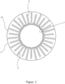
- Figure 2 shows the contact washer 1 of figure 1 in plan view.
- a set of inner slots 8 extends through the plate 2 from the first face 3 to the second face 4 and from the aperture edge 7 part way to the peripheral edge 5.
- the inner slots 8 are equally spaced around the aperture edge 7 and extend radially outwards.
- a set of outer slots 9 extends through the plate 2 from the first face 3 to the second face 4 and from the peripheral edge 5 part way to the aperture 6.
- the outer slots 9 are equally spaced around the peripheral edge 5 and extend radially inwards.
- the inner slots 8 and outer slots 9 are interdigitated as shown with each inner slot 8 spaced equally from the adjacent outer slots 9 and vice versa.
- the slots 8,9 divide the plate into a number of radially extending fingers 10.
- Shown in figure 3 is a device 11 for the transfer of electric current according to the invention.
- the device 11 comprises first and second electrically conductive members 12,13.
- the first member 12 is spaced apart from the second member 13.
- the second member 13 is adapted to rotate about a rotation axis 14 with respect to the first member 12.
- An electrically insulating rotation axle 15 extends along the rotation axis 14 between the first and second members 12,13.
- the rotation axle 15 extends through the central aperture 6.
- the first member 12 is connected to earth 16.
- the second member 13 is connected to a current source 17 adapted to provide a current to the second member 13.
- a current flows from the current source 17 to the second member 13. From there it flows through the contact washer 1 to the first member 12 and then to earth 16.
- each of the fingers 10 of the washer 1 defined by the inner and outer slots 8,9 abuts either the first member 12 or second member 13. This forces the current to flow along a series of substantially parallel paths radially outwards as shown.
- the current flowing through each point where the washer 1 contacts the first or second member 12,13 is therefore reduced. This reduces the heating at the contact points. More significantly, the repulsive force due to current constriction at each contact point is reduced.
- the repulsive force is a function of the current density. Having inner slots and outer slots 8,9 which divide the washer 1 into around ten fingers for example will typically reduce this repulsive force by a factor of greater than ten for a constant current flowing through the washer 1.
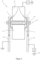
- Shown in figure 4 is a further embodiment of a device 11 for the transfer of electric current according to the invention.
- the device 11 comprises first and third spaced apart electrically conductive members 12,18 in the form of support fingers.
- a second electrically conductive member 13 is arranged between the first and third support fingers 12,18 as shown.
- the second member 13 is typically a wheel.
- the wheel 13 is free to rotate about a rotation axis 14 with respect to the first and third members 12,18.
- a rotation axle 15 extends along the rotation axis 14 from the first member 12, through an aperture 6 in the center of the wheel 13 to the third member 18.
- a first contact washer 1 is sandwiched the wheel 13 and the first member 12.
- a second contact washer 1 is sandwiched between the wheel 13 and the third member 18.
- a current is provided to the edge of the wheel 13 from a current source 17.
- the current flows through the wheel 13 then through the washers 1 and support fingers 12,18 to earth 16, typically via a load 19 as shown.
- the design of the washers 1 reduces the heating at the point of contact between the washers 1 and the members 12,18. it also reduces the repulsive force due to current constriction at the contact points.
- a significant consideration in the design of the device of figure 4 is the Lorentz force.
Landscapes
- Engineering & Computer Science (AREA)
- General Engineering & Computer Science (AREA)
- Mechanical Engineering (AREA)
- Connections Effected By Soldering, Adhesion, Or Permanent Deformation (AREA)
- Gasket Seals (AREA)
- Connections By Means Of Piercing Elements, Nuts, Or Screws (AREA)
Description
- The present invention relates to a device for the transfer of electric current comprising first and second spaced apart electrically conductive members and a contact washer sandwiched therebetween.
- It is often desired to transfer current from one electrically conductive member to another, where one of the members rotates relative to the other. For small angles of rotation a flexible connector can be used. This is difficult for large angles of rotation and impossible for continuous rotation.
- In the case of continuous rotation it is known to sandwich an electrically conductive washer between the two electrically conductive members. For high current applications, typically for currents over around 10,000 Amps) this arrangement has a number of drawbacks. Whilst the washer is substantially flat it tends to contact each member at only a very few discreet contact points. This results in a high joint resistance which in turn causes overheating. Further, current constriction at these contact points causes a repulsive force between the washer and the member. A large spring force is required to maintain the washer in contact with the member. This is typically achieved by compressing the washer. However, known washers exert a maximum restoring spring force in the region of the mid compression point which drops away sharply from this point. The spring force exerted by the washer can therefore be difficult to control and can change if the washer is compressed in use.
US3801753A discloses a known device for transferring electric current between two members. - The present invention seeks to overcome the problems of the prior art.
- The invention is as defined in claim 1.
- Accordingly, the invention provides a device comprising a contact washer comprising a metal plate defined by first and second faces and a peripheral edge, the metal plate having an aperture extending therethrough defined by an aperture edge of the plate;
the washer further comprising at least one of - - (a) a plurality of inner slots, each inner slot extending through the plate from the first face to the second face and from the aperture edge part way to the peripheral edge; and
- (b) a plurality of outer slots, each outer slot extending through the plate from the first face to the second face and from the peripheral edge part way to the aperture edge.
- The slots in the washer divide the washer into a number of fingers. In use each finger independently contacts the adjacent member. This forces the current flowing through the washer from the central aperture to the peripheral edge flow in a number of parallel radial paths. This significantly reduces the heating at the contact between washer and member. It also significantly reduces the repulsive force due to current constriction. Further, as the washer is compressed the fingers tend to twist. This produces a restoring spring force which is approximately linearly dependent on the degree of compression of the washer.
- The contact washer comprises a plurality of inner slots.
- According to the invention the inner slots are equally spaced apart around the aperture edge.
- The contact washer comprises a plurality of outer slots.
- According to the invention the outer slots are equally spaced apart around the peripheral edge.
- According to the invention the contact washer comprises a plurality of inner slots and a plurality of outer slots, the inner slots and outer slots being interdigitated.
- Preferably the inner slots are equally spaced apart around the aperture edge and the outer slots are equally spaced apart around the peripheral edge, each inner slot being equally spaced apart from the adjacent outer slots and vice versa.
- The metal plate is frustoconical.
- Preferably the contact washer further comprises an electrically conductive coating layer coating the metal plate, the electrical conductivity of the coating layer being higher than that of the metal plate.
- According to the invention the device for the transfer of electric current further comprises
- a first electrically conductive member;
- a second electrically conductive member spaced apart from the first;
- the second member being adapted to rotate with respect to the first about a rotation axis; and,
- a contact washer as described previously sandwiched between the first and second members with the rotation axis passing through the aperture, the peripheral edge abutting one member and the aperture edge abutting the other member.
- Preferably the device further comprises a third electrically conductive member arranged on the opposite side of the second electrically conductive member to the first; and,
a further contact washer as described previously sandwiched between the second and third members with the rotation axis passing through the aperture, the peripheral edge of the further contact washer abutting one of the second and third members and the aperture edge of the further contact washer abutting the other of the second and third members. - Preferably the device further comprises a rotation axle extending along the rotation axis from the first member, through an aperture in the second member to the third member.
- Preferably the second member is a wheel.
- Preferably the device further comprises a current source connected to one of the first and second members.
- Preferably the device further comprises a load connected to the other of the first and second members.
- The present invention will now be described by way of example only and not in any limitative sense with reference to the accompanying drawings in which
-
Figure 1 shows, in perspective view, a contact washer; -
Figure 2 shows the contact washer offigure 1 in plan view; -
Figure 3 shows a device for the transfer of electric current according to the invention; and -
Figure 4 shows a further embodiment of a device for the transfer of electric current according to the invention in cross section. - Shown in
figure 1 is a contact washer 1. The contact washer 1 comprises afrustoconical metal plate 2. Themetal plate 2 is typically a copper alloy, for example CW106 chromium, copper, zirconium. Themetal plate 2 is optionally coated in a metal film of a high electrical conductivity than the metal plate. The film can for example be a silver film which is preferred due to its hardness and low oxidation. - The
metal plate 2 is defined first andsecond faces peripheral edge 5. Anaperture 6 extends through the center of theplate 2 and is defined by anaperture edge 7 of theplate 2. -
Figure 2 shows the contact washer 1 offigure 1 in plan view. A set ofinner slots 8 extends through theplate 2 from thefirst face 3 to thesecond face 4 and from theaperture edge 7 part way to theperipheral edge 5. Theinner slots 8 are equally spaced around theaperture edge 7 and extend radially outwards. - A set of
outer slots 9 extends through theplate 2 from thefirst face 3 to thesecond face 4 and from theperipheral edge 5 part way to theaperture 6. Theouter slots 9 are equally spaced around theperipheral edge 5 and extend radially inwards. - The
inner slots 8 andouter slots 9 are interdigitated as shown with eachinner slot 8 spaced equally from the adjacentouter slots 9 and vice versa. Theslots fingers 10. - Shown in
figure 3 is adevice 11 for the transfer of electric current according to the invention. Thedevice 11 comprises first and second electricallyconductive members first member 12 is spaced apart from thesecond member 13. Thesecond member 13 is adapted to rotate about arotation axis 14 with respect to thefirst member 12. An electrically insulatingrotation axle 15 extends along therotation axis 14 between the first andsecond members - Sandwiched between the first and
second members - The
rotation axle 15 extends through thecentral aperture 6. Thefirst member 12 is connected toearth 16. Thesecond member 13 is connected to acurrent source 17 adapted to provide a current to thesecond member 13. - In use a current flows from the
current source 17 to thesecond member 13. From there it flows through the contact washer 1 to thefirst member 12 and then toearth 16. As previously described, each of thefingers 10 of the washer 1 defined by the inner andouter slots first member 12 orsecond member 13. This forces the current to flow along a series of substantially parallel paths radially outwards as shown. The current flowing through each point where the washer 1 contacts the first orsecond member outer slots - Shown in
figure 4 is a further embodiment of adevice 11 for the transfer of electric current according to the invention. Thedevice 11 comprises first and third spaced apart electricallyconductive members conductive member 13 is arranged between the first andthird support fingers second member 13 is typically a wheel. Thewheel 13 is free to rotate about arotation axis 14 with respect to the first andthird members rotation axle 15 extends along therotation axis 14 from thefirst member 12, through anaperture 6 in the center of thewheel 13 to thethird member 18. A first contact washer 1 is sandwiched thewheel 13 and thefirst member 12. A second contact washer 1 is sandwiched between thewheel 13 and thethird member 18. - in use a current is provided to the edge of the
wheel 13 from acurrent source 17. The current flows through thewheel 13 then through the washers 1 and supportfingers earth 16, typically via aload 19 as shown. As before, the design of the washers 1 reduces the heating at the point of contact between the washers 1 and themembers - A significant consideration in the design of the device of
figure 4 is the Lorentz force. Currents flow through the twosupport fingers support fingers support fingers - As the
wheel 13 turns then friction between thewheel 13 and the washers 1 produces a frictional force on theperipheral edge 5 of each washer 1. This twists the fingers of each washer 1 slightly. As discussed above, when the fingers of a contact washer 1 are twisted then when the washer 1 is compressed it produces a restoring spring force which only weakly depends on the degree of compression. Accordingly, even though thesupport fingers wheel 13 is therefore substantially unchanged.
Claims (8)
- A device (11) for the transfer of electric current comprisinga first electrically conductive member (12);a second electrically conductive member (13) spaced apart from the first (12);the second electrically conductive member (13) being adapted to rotate with respect to the first (12) about a rotation axis; anda contact washer (1), the contact washer (1) comprising a frustoconical metal plate (2) defined by first (3) and second (4) faces and a peripheral edge (5), the metal plate (2) having an aperture (6) extending therethrough defined by an aperture edge (7) of the plate (2) the washer (1) further comprising(a) a plurality of inner slots (8) equally spaced apart around the aperture edge (7), each inner slot (8) extending through the plate (2) from the first face (3) to the second face (4) and from the aperture edge (7) part way to the peripheral edge (5); and(b) a plurality of outer slots (9) equally spaced apart around the peripheral edge (5) and interdigitated with the inner slots (8), each outer slot (9) extending through the plate (2) from the first face (3) to the second face (4) and from the peripheral edge (5) part way to the aperture edge (7);the contact washer (1) being sandwiched between the first (12) and second (13) members with the rotation axis passing through the aperture (6), the peripheral edge (5) abutting one member and the aperture edge (7) abutting the other member.
- A device (11) as claimed in claim 1, further comprising a third electrically conductive member (18)arranged on the opposite side of the second electrically conductive member (13) to the first (12); and,a further contact washer (1) comprising, a frustoconical metal plate (2) defined by first (3) and second (4) faces and a peripheral edge (5), the metal plate (2) having an aperture (6) extending therethrough defined by an aperture edge (7) of the plate (2) the washer (1) further comprising (a) a plurality of inner slots (8) equally spaced apart around the aperture edge (7), each inner slot (8) extending through the plate (2) from the first face (3) to the second face (4) and from the aperture edge (7) part way to the peripheral edge (5); and (b) a plurality of outer slots (9) equally spaced apart around the peripheral edge (5) and interdigitated with the inner slots (8), each outer slot (9) extending through the plate (2) from the first face (3) to the second face (4) and from the peripheral edge (5) part way to the aperture edge (7), the further contact washer (1) being sandwiched between the second (13) and third (18)members with the rotation axis passing through the aperture (6), the peripheral edge (5) of the further contact washer (1) abutting one of the second (13) and third (18) members and the aperture edge (7) of the further contact washer (1) abutting the other of the second (13) and third (18) members.
- A device (11) as claimed in claim 2, further comprising a rotation axle (14) extending along the rotation axis from the first member (12), through an aperture in the second member (13) to the third member (18).
- A device (11) as claimed in any one of claims 1 to 3, wherein the second member (13) is a wheel.
- A device (11) as claimed in any one of claims 1 to 4, further comprising a current source (17) connected to one of the first (12) and second (13) members.
- A device (11) as claimed in claim 5, further comprising a load (19) connected to the other of the first (12) and second (13) members.
- A device (11) as claimed in claim 1 wherein each inner slot (8) is equally spaced apart from the adjacent outer slots (9) and vice versa.
- A device (11) as claimed in any one of claims 1 to 7, further comprising an electrically conductive coating layer coating the metal plate (2), the electrical conductivity of the coating layer being higher than that of the metal plate (2).
Applications Claiming Priority (2)
| Application Number | Priority Date | Filing Date | Title |
|---|---|---|---|
| GB1821168.0A GB2581322B (en) | 2018-12-23 | 2018-12-23 | A device for the transfer of electric current including a contact washer |
| PCT/GB2019/053685 WO2020136371A1 (en) | 2018-12-23 | 2019-12-23 | A contact washer and a device for the transfer of electric current including such a washer |
Publications (2)
| Publication Number | Publication Date |
|---|---|
| EP3899294A1 EP3899294A1 (en) | 2021-10-27 |
| EP3899294B1 true EP3899294B1 (en) | 2024-01-24 |
Family
ID=65364321
Family Applications (1)
| Application Number | Title | Priority Date | Filing Date |
|---|---|---|---|
| EP19831863.6A Active EP3899294B1 (en) | 2018-12-23 | 2019-12-23 | Device for the transfer of electric current including a contact washer |
Country Status (4)
| Country | Link |
|---|---|
| EP (1) | EP3899294B1 (en) |
| CN (1) | CN113454351B (en) |
| GB (1) | GB2581322B (en) |
| WO (1) | WO2020136371A1 (en) |
Family Cites Families (20)
| Publication number | Priority date | Publication date | Assignee | Title |
|---|---|---|---|---|
| US2177481A (en) * | 1934-10-05 | 1939-10-24 | Mallory & Co Inc P R | Switch |
| DE1690001B1 (en) * | 1967-07-24 | 1971-02-18 | Siemens Ag | CONTACT DISC FOR MINIATURE MULTIPLE STEP TURN SWITCHES |
| US3801753A (en) * | 1969-06-17 | 1974-04-02 | Gaf Corp | Dial type wafer printed circuit switch |
| CA981352A (en) * | 1972-04-08 | 1976-01-06 | Roberto Plana | Electrical connectors |
| US4347024A (en) * | 1980-08-22 | 1982-08-31 | Eaton Corporation | Tension indicating and lock cone washer |
| GB2124834B (en) * | 1982-07-26 | 1985-11-27 | Video Enterprises Limited | Improvements in or relating to an electrical connector |
| US4512623A (en) * | 1984-02-03 | 1985-04-23 | Allied Corporation | Electrical connector assembly having means for shielding electromagnetic interference |
| US5496142A (en) * | 1993-07-20 | 1996-03-05 | Applied Materials, Inc. | Slotted conical spring washer |
| JPH08167348A (en) * | 1994-12-14 | 1996-06-25 | Matsushita Electric Ind Co Ltd | Rotatable electronic components |
| EP0809264A1 (en) * | 1996-05-24 | 1997-11-26 | SIEMENS MATSUSHITA COMPONENTS GmbH & CO. KG | Device for mutually fixing of ferromagnetic cores and supports for electric windings in inductive components |
| FR2796426A1 (en) * | 1999-07-13 | 2001-01-19 | Gobin Daude | Fastener comprises flexible locking washer and bolt whose shaft fits into it, nut fitted to shaft allowing fastener to be undone and rivet removed |
| JP2005219650A (en) * | 2004-02-06 | 2005-08-18 | Ntn Corp | Bearing device for driving wheel |
| KR20060002075A (en) * | 2004-07-01 | 2006-01-09 | 현대자동차주식회사 | Washers for Seat Mounting |
| CN101385204A (en) * | 2006-02-17 | 2009-03-11 | 森蒂彼得系统有限公司 | High Performance Electrical Connectors |
| US8807601B2 (en) * | 2011-03-01 | 2014-08-19 | Evergreen Tool Co., Inc. | Compression seal assembly |
| JP2012202500A (en) * | 2011-03-25 | 2012-10-22 | Tokyo Electric Power Co Inc:The | Washer |
| CN102200209B (en) * | 2011-05-03 | 2013-08-14 | 吉林市红太阳地热采暖材料销售有限公司 | Interface card of water collecting and diversifying device |
| DE102011109788A1 (en) * | 2011-08-08 | 2013-02-14 | Festo Ag & Co. Kg | Connecting device for connecting a fluid line |
| CN202276022U (en) * | 2011-09-20 | 2012-06-13 | 中兴通讯股份有限公司 | Radio frequency connector |
| EP2987210A4 (en) * | 2013-04-18 | 2016-12-14 | Fci Asia Pte Ltd | Insulation displacement connector and contacts thereof |
-
2018
- 2018-12-23 GB GB1821168.0A patent/GB2581322B/en active Active
-
2019
- 2019-12-23 WO PCT/GB2019/053685 patent/WO2020136371A1/en not_active Ceased
- 2019-12-23 CN CN201980083502.6A patent/CN113454351B/en active Active
- 2019-12-23 EP EP19831863.6A patent/EP3899294B1/en active Active
Also Published As
| Publication number | Publication date |
|---|---|
| EP3899294A1 (en) | 2021-10-27 |
| GB2581322B (en) | 2022-09-21 |
| GB2581322A (en) | 2020-08-19 |
| GB201821168D0 (en) | 2019-02-06 |
| CN113454351B (en) | 2023-04-18 |
| WO2020136371A1 (en) | 2020-07-02 |
| CN113454351A (en) | 2021-09-28 |
Similar Documents
| Publication | Publication Date | Title |
|---|---|---|
| US7880582B2 (en) | Layered electrically conductive material | |
| US9543679B2 (en) | Electrical contact assembly | |
| US3259727A (en) | Low-resistance connector | |
| JP2012009411A (en) | Conductor connection washer, connection mechanism using it and method of manufacturing conductor connection washer | |
| CA2186970A1 (en) | Electronic Devices Having Reduced Destruction of Internal Elements Upon Malfunction | |
| US11450994B2 (en) | Plug connection having redundancy and vehicle having such a connection | |
| GB2581322A (en) | A contact washer and a device for the transfer of electric current including such a washer | |
| WO2019065515A1 (en) | Pressure-sensitive sensor | |
| US2870276A (en) | Rotary electric switch | |
| US12075702B2 (en) | Conductive particle interconnect switch | |
| WO2019075685A1 (en) | Surface mounted fuse device having positive temperature coefficient body | |
| GB2442545A (en) | Magnetic Transistor Structure | |
| US2177291A (en) | Variable resistance device | |
| USRE25510E (en) | Electrical resistor | |
| JP7206357B2 (en) | Contact rings for highly dynamic applications | |
| US3159722A (en) | Rotary switch | |
| US2885519A (en) | Potentiometer wiper arm | |
| DE3586994D1 (en) | ELECTRICAL CONTACT BETWEEN METALS AND RESISTANCE ELEMENTS. | |
| CN107240531A (en) | A kind of contact structures and switching device | |
| US2926229A (en) | Anti-chatter switching device | |
| SU968526A1 (en) | Spiral with non-linear characteristics | |
| JPS62105022A (en) | Electrical-mechanical converter | |
| JPH06260054A (en) | Pressure-sensitive switch | |
| US2906984A (en) | Contact assembly and control structure | |
| JP2025508246A (en) | Force Sensing Device |
Legal Events
| Date | Code | Title | Description |
|---|---|---|---|
| STAA | Information on the status of an ep patent application or granted ep patent |
Free format text: STATUS: UNKNOWN |
|
| STAA | Information on the status of an ep patent application or granted ep patent |
Free format text: STATUS: THE INTERNATIONAL PUBLICATION HAS BEEN MADE |
|
| PUAI | Public reference made under article 153(3) epc to a published international application that has entered the european phase |
Free format text: ORIGINAL CODE: 0009012 |
|
| STAA | Information on the status of an ep patent application or granted ep patent |
Free format text: STATUS: REQUEST FOR EXAMINATION WAS MADE |
|
| 17P | Request for examination filed |
Effective date: 20210521 |
|
| AK | Designated contracting states |
Kind code of ref document: A1 Designated state(s): AL AT BE BG CH CY CZ DE DK EE ES FI FR GB GR HR HU IE IS IT LI LT LU LV MC MK MT NL NO PL PT RO RS SE SI SK SM TR |
|
| DAV | Request for validation of the european patent (deleted) | ||
| DAX | Request for extension of the european patent (deleted) | ||
| GRAP | Despatch of communication of intention to grant a patent |
Free format text: ORIGINAL CODE: EPIDOSNIGR1 |
|
| STAA | Information on the status of an ep patent application or granted ep patent |
Free format text: STATUS: GRANT OF PATENT IS INTENDED |
|
| INTG | Intention to grant announced |
Effective date: 20230816 |
|
| GRAS | Grant fee paid |
Free format text: ORIGINAL CODE: EPIDOSNIGR3 |
|
| GRAA | (expected) grant |
Free format text: ORIGINAL CODE: 0009210 |
|
| STAA | Information on the status of an ep patent application or granted ep patent |
Free format text: STATUS: THE PATENT HAS BEEN GRANTED |
|
| RBV | Designated contracting states (corrected) |
Designated state(s): AL AT BE BG CH CY CZ DE DK EE ES FI FR GR HR HU IE IS IT LI LT LU LV MC MK MT NL NO PL PT RO RS SE SI SK SM TR |
|
| AK | Designated contracting states |
Kind code of ref document: B1 Designated state(s): AL AT BE BG CH CY CZ DE DK EE ES FI FR GR HR HU IE IS IT LI LT LU LV MC MK MT NL NO PL PT RO RS SE SI SK SM TR |
|
| REG | Reference to a national code |
Ref country code: CH Ref legal event code: EP |
|
| REG | Reference to a national code |
Ref country code: IE Ref legal event code: FG4D |
|
| REG | Reference to a national code |
Ref country code: DE Ref legal event code: R096 Ref document number: 602019045731 Country of ref document: DE |
|
| REG | Reference to a national code |
Ref country code: LT Ref legal event code: MG9D |
|
| REG | Reference to a national code |
Ref country code: NL Ref legal event code: MP Effective date: 20240124 |
|
| PG25 | Lapsed in a contracting state [announced via postgrant information from national office to epo] |
Ref country code: NL Free format text: LAPSE BECAUSE OF FAILURE TO SUBMIT A TRANSLATION OF THE DESCRIPTION OR TO PAY THE FEE WITHIN THE PRESCRIBED TIME-LIMIT Effective date: 20240124 |
|
| PG25 | Lapsed in a contracting state [announced via postgrant information from national office to epo] |
Ref country code: NL Free format text: LAPSE BECAUSE OF FAILURE TO SUBMIT A TRANSLATION OF THE DESCRIPTION OR TO PAY THE FEE WITHIN THE PRESCRIBED TIME-LIMIT Effective date: 20240124 |
|
| PG25 | Lapsed in a contracting state [announced via postgrant information from national office to epo] |
Ref country code: IS Free format text: LAPSE BECAUSE OF FAILURE TO SUBMIT A TRANSLATION OF THE DESCRIPTION OR TO PAY THE FEE WITHIN THE PRESCRIBED TIME-LIMIT Effective date: 20240524 |
|
| PG25 | Lapsed in a contracting state [announced via postgrant information from national office to epo] |
Ref country code: LT Free format text: LAPSE BECAUSE OF FAILURE TO SUBMIT A TRANSLATION OF THE DESCRIPTION OR TO PAY THE FEE WITHIN THE PRESCRIBED TIME-LIMIT Effective date: 20240124 |
|
| PG25 | Lapsed in a contracting state [announced via postgrant information from national office to epo] |
Ref country code: GR Free format text: LAPSE BECAUSE OF FAILURE TO SUBMIT A TRANSLATION OF THE DESCRIPTION OR TO PAY THE FEE WITHIN THE PRESCRIBED TIME-LIMIT Effective date: 20240425 |
|
| REG | Reference to a national code |
Ref country code: AT Ref legal event code: MK05 Ref document number: 1652404 Country of ref document: AT Kind code of ref document: T Effective date: 20240124 |
|
| PG25 | Lapsed in a contracting state [announced via postgrant information from national office to epo] |
Ref country code: HR Free format text: LAPSE BECAUSE OF FAILURE TO SUBMIT A TRANSLATION OF THE DESCRIPTION OR TO PAY THE FEE WITHIN THE PRESCRIBED TIME-LIMIT Effective date: 20240124 Ref country code: RS Free format text: LAPSE BECAUSE OF FAILURE TO SUBMIT A TRANSLATION OF THE DESCRIPTION OR TO PAY THE FEE WITHIN THE PRESCRIBED TIME-LIMIT Effective date: 20240424 |
|
| PG25 | Lapsed in a contracting state [announced via postgrant information from national office to epo] |
Ref country code: ES Free format text: LAPSE BECAUSE OF FAILURE TO SUBMIT A TRANSLATION OF THE DESCRIPTION OR TO PAY THE FEE WITHIN THE PRESCRIBED TIME-LIMIT Effective date: 20240124 |
|
| PG25 | Lapsed in a contracting state [announced via postgrant information from national office to epo] |
Ref country code: AT Free format text: LAPSE BECAUSE OF FAILURE TO SUBMIT A TRANSLATION OF THE DESCRIPTION OR TO PAY THE FEE WITHIN THE PRESCRIBED TIME-LIMIT Effective date: 20240124 |
|
| PG25 | Lapsed in a contracting state [announced via postgrant information from national office to epo] |
Ref country code: RS Free format text: LAPSE BECAUSE OF FAILURE TO SUBMIT A TRANSLATION OF THE DESCRIPTION OR TO PAY THE FEE WITHIN THE PRESCRIBED TIME-LIMIT Effective date: 20240424 Ref country code: NO Free format text: LAPSE BECAUSE OF FAILURE TO SUBMIT A TRANSLATION OF THE DESCRIPTION OR TO PAY THE FEE WITHIN THE PRESCRIBED TIME-LIMIT Effective date: 20240424 Ref country code: LT Free format text: LAPSE BECAUSE OF FAILURE TO SUBMIT A TRANSLATION OF THE DESCRIPTION OR TO PAY THE FEE WITHIN THE PRESCRIBED TIME-LIMIT Effective date: 20240124 Ref country code: IS Free format text: LAPSE BECAUSE OF FAILURE TO SUBMIT A TRANSLATION OF THE DESCRIPTION OR TO PAY THE FEE WITHIN THE PRESCRIBED TIME-LIMIT Effective date: 20240524 Ref country code: HR Free format text: LAPSE BECAUSE OF FAILURE TO SUBMIT A TRANSLATION OF THE DESCRIPTION OR TO PAY THE FEE WITHIN THE PRESCRIBED TIME-LIMIT Effective date: 20240124 Ref country code: GR Free format text: LAPSE BECAUSE OF FAILURE TO SUBMIT A TRANSLATION OF THE DESCRIPTION OR TO PAY THE FEE WITHIN THE PRESCRIBED TIME-LIMIT Effective date: 20240425 Ref country code: FI Free format text: LAPSE BECAUSE OF FAILURE TO SUBMIT A TRANSLATION OF THE DESCRIPTION OR TO PAY THE FEE WITHIN THE PRESCRIBED TIME-LIMIT Effective date: 20240124 Ref country code: ES Free format text: LAPSE BECAUSE OF FAILURE TO SUBMIT A TRANSLATION OF THE DESCRIPTION OR TO PAY THE FEE WITHIN THE PRESCRIBED TIME-LIMIT Effective date: 20240124 Ref country code: BG Free format text: LAPSE BECAUSE OF FAILURE TO SUBMIT A TRANSLATION OF THE DESCRIPTION OR TO PAY THE FEE WITHIN THE PRESCRIBED TIME-LIMIT Effective date: 20240124 Ref country code: AT Free format text: LAPSE BECAUSE OF FAILURE TO SUBMIT A TRANSLATION OF THE DESCRIPTION OR TO PAY THE FEE WITHIN THE PRESCRIBED TIME-LIMIT Effective date: 20240124 |
|
| PG25 | Lapsed in a contracting state [announced via postgrant information from national office to epo] |
Ref country code: PT Free format text: LAPSE BECAUSE OF FAILURE TO SUBMIT A TRANSLATION OF THE DESCRIPTION OR TO PAY THE FEE WITHIN THE PRESCRIBED TIME-LIMIT Effective date: 20240524 Ref country code: PL Free format text: LAPSE BECAUSE OF FAILURE TO SUBMIT A TRANSLATION OF THE DESCRIPTION OR TO PAY THE FEE WITHIN THE PRESCRIBED TIME-LIMIT Effective date: 20240124 |
|
| PG25 | Lapsed in a contracting state [announced via postgrant information from national office to epo] |
Ref country code: SE Free format text: LAPSE BECAUSE OF FAILURE TO SUBMIT A TRANSLATION OF THE DESCRIPTION OR TO PAY THE FEE WITHIN THE PRESCRIBED TIME-LIMIT Effective date: 20240124 Ref country code: PT Free format text: LAPSE BECAUSE OF FAILURE TO SUBMIT A TRANSLATION OF THE DESCRIPTION OR TO PAY THE FEE WITHIN THE PRESCRIBED TIME-LIMIT Effective date: 20240524 Ref country code: PL Free format text: LAPSE BECAUSE OF FAILURE TO SUBMIT A TRANSLATION OF THE DESCRIPTION OR TO PAY THE FEE WITHIN THE PRESCRIBED TIME-LIMIT Effective date: 20240124 Ref country code: LV Free format text: LAPSE BECAUSE OF FAILURE TO SUBMIT A TRANSLATION OF THE DESCRIPTION OR TO PAY THE FEE WITHIN THE PRESCRIBED TIME-LIMIT Effective date: 20240124 |
|
| PG25 | Lapsed in a contracting state [announced via postgrant information from national office to epo] |
Ref country code: DK Free format text: LAPSE BECAUSE OF FAILURE TO SUBMIT A TRANSLATION OF THE DESCRIPTION OR TO PAY THE FEE WITHIN THE PRESCRIBED TIME-LIMIT Effective date: 20240124 |
|
| PG25 | Lapsed in a contracting state [announced via postgrant information from national office to epo] |
Ref country code: SM Free format text: LAPSE BECAUSE OF FAILURE TO SUBMIT A TRANSLATION OF THE DESCRIPTION OR TO PAY THE FEE WITHIN THE PRESCRIBED TIME-LIMIT Effective date: 20240124 |
|
| PG25 | Lapsed in a contracting state [announced via postgrant information from national office to epo] |
Ref country code: CZ Free format text: LAPSE BECAUSE OF FAILURE TO SUBMIT A TRANSLATION OF THE DESCRIPTION OR TO PAY THE FEE WITHIN THE PRESCRIBED TIME-LIMIT Effective date: 20240124 Ref country code: EE Free format text: LAPSE BECAUSE OF FAILURE TO SUBMIT A TRANSLATION OF THE DESCRIPTION OR TO PAY THE FEE WITHIN THE PRESCRIBED TIME-LIMIT Effective date: 20240124 |
|
| REG | Reference to a national code |
Ref country code: DE Ref legal event code: R097 Ref document number: 602019045731 Country of ref document: DE |
|
| PG25 | Lapsed in a contracting state [announced via postgrant information from national office to epo] |
Ref country code: SK Free format text: LAPSE BECAUSE OF FAILURE TO SUBMIT A TRANSLATION OF THE DESCRIPTION OR TO PAY THE FEE WITHIN THE PRESCRIBED TIME-LIMIT Effective date: 20240124 |
|
| PG25 | Lapsed in a contracting state [announced via postgrant information from national office to epo] |
Ref country code: SM Free format text: LAPSE BECAUSE OF FAILURE TO SUBMIT A TRANSLATION OF THE DESCRIPTION OR TO PAY THE FEE WITHIN THE PRESCRIBED TIME-LIMIT Effective date: 20240124 Ref country code: SK Free format text: LAPSE BECAUSE OF FAILURE TO SUBMIT A TRANSLATION OF THE DESCRIPTION OR TO PAY THE FEE WITHIN THE PRESCRIBED TIME-LIMIT Effective date: 20240124 Ref country code: EE Free format text: LAPSE BECAUSE OF FAILURE TO SUBMIT A TRANSLATION OF THE DESCRIPTION OR TO PAY THE FEE WITHIN THE PRESCRIBED TIME-LIMIT Effective date: 20240124 Ref country code: DK Free format text: LAPSE BECAUSE OF FAILURE TO SUBMIT A TRANSLATION OF THE DESCRIPTION OR TO PAY THE FEE WITHIN THE PRESCRIBED TIME-LIMIT Effective date: 20240124 Ref country code: CZ Free format text: LAPSE BECAUSE OF FAILURE TO SUBMIT A TRANSLATION OF THE DESCRIPTION OR TO PAY THE FEE WITHIN THE PRESCRIBED TIME-LIMIT Effective date: 20240124 |
|
| PLBE | No opposition filed within time limit |
Free format text: ORIGINAL CODE: 0009261 |
|
| STAA | Information on the status of an ep patent application or granted ep patent |
Free format text: STATUS: NO OPPOSITION FILED WITHIN TIME LIMIT |
|
| 26N | No opposition filed |
Effective date: 20241025 |
|
| PG25 | Lapsed in a contracting state [announced via postgrant information from national office to epo] |
Ref country code: SI Free format text: LAPSE BECAUSE OF FAILURE TO SUBMIT A TRANSLATION OF THE DESCRIPTION OR TO PAY THE FEE WITHIN THE PRESCRIBED TIME-LIMIT Effective date: 20240124 |
|
| PG25 | Lapsed in a contracting state [announced via postgrant information from national office to epo] |
Ref country code: MC Free format text: LAPSE BECAUSE OF FAILURE TO SUBMIT A TRANSLATION OF THE DESCRIPTION OR TO PAY THE FEE WITHIN THE PRESCRIBED TIME-LIMIT Effective date: 20240124 |
|
| REG | Reference to a national code |
Ref country code: CH Ref legal event code: PL |
|
| PG25 | Lapsed in a contracting state [announced via postgrant information from national office to epo] |
Ref country code: LU Free format text: LAPSE BECAUSE OF NON-PAYMENT OF DUE FEES Effective date: 20241223 |
|
| REG | Reference to a national code |
Ref country code: BE Ref legal event code: MM Effective date: 20241231 |
|
| PG25 | Lapsed in a contracting state [announced via postgrant information from national office to epo] |
Ref country code: BE Free format text: LAPSE BECAUSE OF NON-PAYMENT OF DUE FEES Effective date: 20241231 |
|
| PG25 | Lapsed in a contracting state [announced via postgrant information from national office to epo] |
Ref country code: CH Free format text: LAPSE BECAUSE OF NON-PAYMENT OF DUE FEES Effective date: 20241231 |
|
| PG25 | Lapsed in a contracting state [announced via postgrant information from national office to epo] |
Ref country code: IE Free format text: LAPSE BECAUSE OF NON-PAYMENT OF DUE FEES Effective date: 20241223 |
|
| PG25 | Lapsed in a contracting state [announced via postgrant information from national office to epo] |
Ref country code: RO Free format text: LAPSE BECAUSE OF FAILURE TO SUBMIT A TRANSLATION OF THE DESCRIPTION OR TO PAY THE FEE WITHIN THE PRESCRIBED TIME-LIMIT Effective date: 20240124 |
|
| PGFP | Annual fee paid to national office [announced via postgrant information from national office to epo] |
Ref country code: IT Payment date: 20251217 Year of fee payment: 7 |
|
| PGFP | Annual fee paid to national office [announced via postgrant information from national office to epo] |
Ref country code: FR Payment date: 20251230 Year of fee payment: 7 |
|
| PGFP | Annual fee paid to national office [announced via postgrant information from national office to epo] |
Ref country code: DE Payment date: 20251216 Year of fee payment: 7 |
|
| PG25 | Lapsed in a contracting state [announced via postgrant information from national office to epo] |
Ref country code: CY Free format text: LAPSE BECAUSE OF FAILURE TO SUBMIT A TRANSLATION OF THE DESCRIPTION OR TO PAY THE FEE WITHIN THE PRESCRIBED TIME-LIMIT Effective date: 20240124 |