EP3899057B1 - Method and device for direct reduction with electrically heated reducing gas - Google Patents
Method and device for direct reduction with electrically heated reducing gas Download PDFInfo
- Publication number
- EP3899057B1 EP3899057B1 EP19827679.2A EP19827679A EP3899057B1 EP 3899057 B1 EP3899057 B1 EP 3899057B1 EP 19827679 A EP19827679 A EP 19827679A EP 3899057 B1 EP3899057 B1 EP 3899057B1
- Authority
- EP
- European Patent Office
- Prior art keywords
- gas
- reformer
- reduction
- heating chamber
- heating
- Prior art date
- Legal status (The legal status is an assumption and is not a legal conclusion. Google has not performed a legal analysis and makes no representation as to the accuracy of the status listed.)
- Active
Links
- 230000009467 reduction Effects 0.000 title claims description 125
- 238000000034 method Methods 0.000 title claims description 34
- 230000001603 reducing effect Effects 0.000 title description 120
- 239000007789 gas Substances 0.000 claims description 509
- 238000010438 heat treatment Methods 0.000 claims description 172
- 239000002243 precursor Substances 0.000 claims description 133
- 150000004706 metal oxides Chemical class 0.000 claims description 61
- 229910044991 metal oxide Inorganic materials 0.000 claims description 58
- 230000003197 catalytic effect Effects 0.000 claims description 12
- 238000011065 in-situ storage Methods 0.000 claims description 11
- 238000001833 catalytic reforming Methods 0.000 claims description 8
- 238000002360 preparation method Methods 0.000 claims description 7
- 238000004519 manufacturing process Methods 0.000 claims description 5
- 238000006722 reduction reaction Methods 0.000 description 104
- VNWKTOKETHGBQD-UHFFFAOYSA-N methane Chemical compound C VNWKTOKETHGBQD-UHFFFAOYSA-N 0.000 description 28
- 239000000203 mixture Substances 0.000 description 28
- 229930195733 hydrocarbon Natural products 0.000 description 24
- 150000002430 hydrocarbons Chemical class 0.000 description 22
- 239000000463 material Substances 0.000 description 19
- 239000004215 Carbon black (E152) Substances 0.000 description 17
- 239000012159 carrier gas Substances 0.000 description 14
- UQSXHKLRYXJYBZ-UHFFFAOYSA-N iron oxide Inorganic materials [Fe]=O UQSXHKLRYXJYBZ-UHFFFAOYSA-N 0.000 description 14
- 238000006243 chemical reaction Methods 0.000 description 12
- 235000013980 iron oxide Nutrition 0.000 description 12
- 238000002407 reforming Methods 0.000 description 11
- VBMVTYDPPZVILR-UHFFFAOYSA-N iron(2+);oxygen(2-) Chemical class [O-2].[Fe+2] VBMVTYDPPZVILR-UHFFFAOYSA-N 0.000 description 10
- 239000003345 natural gas Substances 0.000 description 10
- 239000003915 liquefied petroleum gas Substances 0.000 description 9
- 229910052760 oxygen Inorganic materials 0.000 description 8
- 239000000047 product Substances 0.000 description 8
- 230000008569 process Effects 0.000 description 7
- 238000011946 reduction process Methods 0.000 description 7
- UHOVQNZJYSORNB-UHFFFAOYSA-N Benzene Chemical compound C1=CC=CC=C1 UHOVQNZJYSORNB-UHFFFAOYSA-N 0.000 description 6
- XEEYBQQBJWHFJM-UHFFFAOYSA-N Iron Chemical compound [Fe] XEEYBQQBJWHFJM-UHFFFAOYSA-N 0.000 description 6
- YXFVVABEGXRONW-UHFFFAOYSA-N Toluene Chemical compound CC1=CC=CC=C1 YXFVVABEGXRONW-UHFFFAOYSA-N 0.000 description 6
- QVGXLLKOCUKJST-UHFFFAOYSA-N atomic oxygen Chemical compound [O] QVGXLLKOCUKJST-UHFFFAOYSA-N 0.000 description 6
- 230000008901 benefit Effects 0.000 description 6
- 229910002091 carbon monoxide Inorganic materials 0.000 description 6
- 230000006378 damage Effects 0.000 description 6
- 230000002349 favourable effect Effects 0.000 description 6
- 239000001301 oxygen Substances 0.000 description 6
- UGFAIRIUMAVXCW-UHFFFAOYSA-N Carbon monoxide Chemical compound [O+]#[C-] UGFAIRIUMAVXCW-UHFFFAOYSA-N 0.000 description 5
- 239000003054 catalyst Substances 0.000 description 5
- 238000002485 combustion reaction Methods 0.000 description 5
- OKTJSMMVPCPJKN-UHFFFAOYSA-N Carbon Chemical compound [C] OKTJSMMVPCPJKN-UHFFFAOYSA-N 0.000 description 4
- UFHFLCQGNIYNRP-UHFFFAOYSA-N Hydrogen Chemical compound [H][H] UFHFLCQGNIYNRP-UHFFFAOYSA-N 0.000 description 4
- 229910052799 carbon Inorganic materials 0.000 description 4
- 238000005255 carburizing Methods 0.000 description 4
- 239000000571 coke Substances 0.000 description 4
- 238000001816 cooling Methods 0.000 description 4
- 238000007599 discharging Methods 0.000 description 4
- 230000000694 effects Effects 0.000 description 4
- 229910052739 hydrogen Inorganic materials 0.000 description 4
- 238000012545 processing Methods 0.000 description 4
- 150000001875 compounds Chemical class 0.000 description 3
- 239000001257 hydrogen Substances 0.000 description 3
- 239000003949 liquefied natural gas Substances 0.000 description 3
- -1 methane Chemical class 0.000 description 3
- 238000002156 mixing Methods 0.000 description 3
- 230000003647 oxidation Effects 0.000 description 3
- 238000007254 oxidation reaction Methods 0.000 description 3
- 239000007787 solid Substances 0.000 description 3
- 238000012546 transfer Methods 0.000 description 3
- 238000011144 upstream manufacturing Methods 0.000 description 3
- 150000001338 aliphatic hydrocarbons Chemical class 0.000 description 2
- 150000004945 aromatic hydrocarbons Chemical class 0.000 description 2
- 230000015572 biosynthetic process Effects 0.000 description 2
- 239000007795 chemical reaction product Substances 0.000 description 2
- 239000011261 inert gas Substances 0.000 description 2
- 229910052742 iron Inorganic materials 0.000 description 2
- 239000008188 pellet Substances 0.000 description 2
- 230000005855 radiation Effects 0.000 description 2
- 230000001105 regulatory effect Effects 0.000 description 2
- 239000004071 soot Substances 0.000 description 2
- 239000000126 substance Substances 0.000 description 2
- MYMOFIZGZYHOMD-UHFFFAOYSA-N Dioxygen Chemical compound O=O MYMOFIZGZYHOMD-UHFFFAOYSA-N 0.000 description 1
- YZCKVEUIGOORGS-UHFFFAOYSA-N Hydrogen atom Chemical compound [H] YZCKVEUIGOORGS-UHFFFAOYSA-N 0.000 description 1
- 238000003723 Smelting Methods 0.000 description 1
- 238000005054 agglomeration Methods 0.000 description 1
- 230000002776 aggregation Effects 0.000 description 1
- 230000032683 aging Effects 0.000 description 1
- 239000011449 brick Substances 0.000 description 1
- 239000011203 carbon fibre reinforced carbon Substances 0.000 description 1
- 230000015556 catabolic process Effects 0.000 description 1
- 229910001567 cementite Inorganic materials 0.000 description 1
- 239000003638 chemical reducing agent Substances 0.000 description 1
- 239000011248 coating agent Substances 0.000 description 1
- 238000000576 coating method Methods 0.000 description 1
- 238000005056 compaction Methods 0.000 description 1
- 239000000498 cooling water Substances 0.000 description 1
- 230000009849 deactivation Effects 0.000 description 1
- 230000007423 decrease Effects 0.000 description 1
- 238000006731 degradation reaction Methods 0.000 description 1
- 238000013461 design Methods 0.000 description 1
- 229910001882 dioxygen Inorganic materials 0.000 description 1
- 238000010494 dissociation reaction Methods 0.000 description 1
- 230000005593 dissociations Effects 0.000 description 1
- 238000005265 energy consumption Methods 0.000 description 1
- 238000005516 engineering process Methods 0.000 description 1
- 239000002360 explosive Substances 0.000 description 1
- 238000011049 filling Methods 0.000 description 1
- 239000000446 fuel Substances 0.000 description 1
- 150000002431 hydrogen Chemical class 0.000 description 1
- 230000006872 improvement Effects 0.000 description 1
- 230000006698 induction Effects 0.000 description 1
- 238000003780 insertion Methods 0.000 description 1
- 230000037431 insertion Effects 0.000 description 1
- KSOKAHYVTMZFBJ-UHFFFAOYSA-N iron;methane Chemical compound C.[Fe].[Fe].[Fe] KSOKAHYVTMZFBJ-UHFFFAOYSA-N 0.000 description 1
- BKCAZRHVRSPNDV-UHFFFAOYSA-N lead;methane Chemical compound C.[Pb] BKCAZRHVRSPNDV-UHFFFAOYSA-N 0.000 description 1
- 239000007788 liquid Substances 0.000 description 1
- 238000012423 maintenance Methods 0.000 description 1
- 229910052751 metal Inorganic materials 0.000 description 1
- 239000002184 metal Substances 0.000 description 1
- 150000002739 metals Chemical class 0.000 description 1
- 230000001590 oxidative effect Effects 0.000 description 1
- 239000003208 petroleum Substances 0.000 description 1
- 239000002994 raw material Substances 0.000 description 1
- 230000006798 recombination Effects 0.000 description 1
- 238000005215 recombination Methods 0.000 description 1
- 239000011819 refractory material Substances 0.000 description 1
- 238000003860 storage Methods 0.000 description 1
Images


Classifications
-
- C—CHEMISTRY; METALLURGY
- C21—METALLURGY OF IRON
- C21B—MANUFACTURE OF IRON OR STEEL
- C21B13/00—Making spongy iron or liquid steel, by direct processes
- C21B13/0046—Making spongy iron or liquid steel, by direct processes making metallised agglomerates or iron oxide
-
- C—CHEMISTRY; METALLURGY
- C21—METALLURGY OF IRON
- C21B—MANUFACTURE OF IRON OR STEEL
- C21B13/00—Making spongy iron or liquid steel, by direct processes
- C21B13/004—Making spongy iron or liquid steel, by direct processes in a continuous way by reduction from ores
-
- C—CHEMISTRY; METALLURGY
- C21—METALLURGY OF IRON
- C21B—MANUFACTURE OF IRON OR STEEL
- C21B13/00—Making spongy iron or liquid steel, by direct processes
- C21B13/0073—Selection or treatment of the reducing gases
-
- C—CHEMISTRY; METALLURGY
- C21—METALLURGY OF IRON
- C21B—MANUFACTURE OF IRON OR STEEL
- C21B13/00—Making spongy iron or liquid steel, by direct processes
- C21B13/12—Making spongy iron or liquid steel, by direct processes in electric furnaces
-
- C—CHEMISTRY; METALLURGY
- C21—METALLURGY OF IRON
- C21B—MANUFACTURE OF IRON OR STEEL
- C21B2100/00—Handling of exhaust gases produced during the manufacture of iron or steel
- C21B2100/20—Increasing the gas reduction potential of recycled exhaust gases
- C21B2100/22—Increasing the gas reduction potential of recycled exhaust gases by reforming
-
- Y—GENERAL TAGGING OF NEW TECHNOLOGICAL DEVELOPMENTS; GENERAL TAGGING OF CROSS-SECTIONAL TECHNOLOGIES SPANNING OVER SEVERAL SECTIONS OF THE IPC; TECHNICAL SUBJECTS COVERED BY FORMER USPC CROSS-REFERENCE ART COLLECTIONS [XRACs] AND DIGESTS
- Y02—TECHNOLOGIES OR APPLICATIONS FOR MITIGATION OR ADAPTATION AGAINST CLIMATE CHANGE
- Y02P—CLIMATE CHANGE MITIGATION TECHNOLOGIES IN THE PRODUCTION OR PROCESSING OF GOODS
- Y02P10/00—Technologies related to metal processing
- Y02P10/10—Reduction of greenhouse gas [GHG] emissions
- Y02P10/134—Reduction of greenhouse gas [GHG] emissions by avoiding CO2, e.g. using hydrogen
-
- Y—GENERAL TAGGING OF NEW TECHNOLOGICAL DEVELOPMENTS; GENERAL TAGGING OF CROSS-SECTIONAL TECHNOLOGIES SPANNING OVER SEVERAL SECTIONS OF THE IPC; TECHNICAL SUBJECTS COVERED BY FORMER USPC CROSS-REFERENCE ART COLLECTIONS [XRACs] AND DIGESTS
- Y02—TECHNOLOGIES OR APPLICATIONS FOR MITIGATION OR ADAPTATION AGAINST CLIMATE CHANGE
- Y02P—CLIMATE CHANGE MITIGATION TECHNOLOGIES IN THE PRODUCTION OR PROCESSING OF GOODS
- Y02P10/00—Technologies related to metal processing
- Y02P10/10—Reduction of greenhouse gas [GHG] emissions
- Y02P10/143—Reduction of greenhouse gas [GHG] emissions of methane [CH4]
Definitions
- the invention relates to a method for the direct reduction of metal oxides using a reducing gas which is based on at least one precursor gas, at least one precursor gas being based on reformer gas obtained by catalytic reforming of hydrocarbon-containing gas in a reformer. It also relates to a device for the direct reduction of metal oxides by means of a reducing gas, comprising a catalytic reformer for producing a reformer gas, a reformer gas line for discharging reformer gas from the catalytic reformer, a reduction unit, and a reducing gas line for introducing reducing gas into the reduction unit.
- the production of metals by direct reduction of metal oxides by means of a reducing gas produced by reforming gases containing hydrocarbons is known - for example the MIDREX® process for the direct reduction of iron oxides is economically very important.
- the reducing gas is introduced into a reduction shaft filled with the metal oxide and reacts with the filling as it flows through.
- the reaction kinetics for the reduction are more favorable at a higher temperature of the reducing gas - in order to achieve a desired system output at a comparatively lower introduction temperature of the reducing gas, the specific
- the amount of reducing gas and possibly the system pressure must be increased, or raw materials that can be reduced more easily - for example pellets - would have to be used, which are associated with significantly higher costs.
- a method and a device are to be presented which allow the introduction temperature to be increased and the production output to be increased without the disadvantages of known methods.
- Reducing gas is a gas that is introduced into a reduction unit containing the metal oxides to be reduced—for example a reduction shaft or a fluidized bed unit—in order to at least partially reduce the metal oxides there.
- a reducing gas based on at least one precursor gas wherein at least one precursor gas is based on reformer gas obtained by catalytic reforming of hydrocarbon-containing gas in a reformer and is heated by means of electrical energy during the preparation of the reducing gas, is called reducing gas A, for example.
- reducing gas A can be used for direct reduction, or in addition to reducing gas A, another reducing gas or several further reducing gases - also called additional reducing gases - can be used - the conditions specified for reducing gas A do not have to apply to the further reducing gases.
- Catalytic reforming is the reaction of hydrocarbon-containing substances, in particular gases, with H 2 O and CO 2 in the presence of a catalyst in one catalytic reformer for the production of H 2 - and CO-containing gas, which is called reformer gas in this application.
- Reformer gas generally exits the reformer at an exit temperature in the range from 850°C to 970°C.
- the metal oxides preferably include iron oxides, more preferably they are iron oxides.
- Iron oxides are, for example, hematitic or magnetitic ores, or agglomerates such as iron ore pellets.
- At least one precursor gas is used in the preparation of the reducing gas.
- At least one precursor gas is based on the reformer gas; several precursor gases can also be based on the reformer gas.
- at least one precursor gas is heated using electrical energy.
- at least one precursor gas based on reformer gas is heated by means of electrical energy.
- Another precursor gas can, for example
- the reformer gas is the catalytic reforming of hydrocarbon-containing gas - such as natural gas, methane, liquefied natural gas LNG, liquefied petroleum gas LPG, coke oven gas COG, biogas; it can be a pure gas or a mixture of gases - product obtained in a reformer.
- Precursor gas based on the reformer gas can comprise at least a subset of the reformer gas, it can also comprise the entire reformer gas.
- Precursor gas based on the reformer gas can also consist of a subset of the reformer gas or the entire reformer gas.
- Precursor gas based on the reformer gas can also be produced by changing the reformer gas, for example by changing the pressure, temperature, composition.
- the composition can be changed, for example, by supplying other gases - such as natural gas - by separating gas components, by reactions in the reformer gas - such reactions can be caused, for example, by pressure or temperature changes or by supplying other gases.
- At least one precursor gas based on reformer gas is heated by means of electrical energy during the preparation of the reducing gas.
- a further precursor gas or several further precursor gases can also be heated by means of electrical energy.
- the precursor gas based on reformer gas is preferably heated by the electrical energy to a temperature which is to an extent of up to 200° C., preferably up to 100° C., particularly preferably up to 70° C., above that Outlet temperature from the reformer is.
- precursor gas based on reformer gas which exits the reformer at an exit temperature of 900°C, is heated to 970°C by the electrical energy.
- an upper limit of 200° C. preferably up to 100° C., particularly preferably up to 70° C., is provided for the temperature increase for the heating.
- the one further precursor gas or the several further precursor gases that are heated by electrical energy are preferably heated to a temperature which is up to 200° C. above the exit temperature of reformer gas from the reformer.
- the temperature must be increased by at least 10° C., particularly preferably at least 20° C., very particularly preferably at least 30° C., and extremely preferably at least 50° C. above the exit temperature preferred.
- the one further precursor gas or several further precursor gases that are heated by electrical energy are preferably heated to a temperature that is at least 10° C., particularly preferably at least 20° C., very particularly preferably at least 30° C. and most preferably at least 50°C above the outlet temperature.
- the reformer operation can be optimized without the associated lower temperature of the reformer gas having a negative effect on the productivity of the direct reduction.
- Changes in the temperature and also in the composition of the reducing gas favorable for improved productivity of the direct reduction can be carried out after the reforming.
- the reformer does not have to be operated beyond temperatures that are optimal for its function and favorable service life in order to ensure a desired reducing gas temperature or composition.
- the reformer can be operated carefully, which extends its service life, in particular the reformer tubes, due to less creeping in the longitudinal and diameter direction of the reformer tubes, or the service life of the catalyst in the reformer. This increases the efficiency of the direct reduction process.
- a reduced temperature level in the reformer also leads to a reduced temperature of the reformer exhaust gas and a reduced fuel requirement; the associated lower energy loss of the process increases the cost-effectiveness.
- aging-related degradation or deactivation of the catalyst in the reformer can be partially compensated for by the electrical heating, thereby delaying the need for complex and expensive replacement of the catalyst material.
- electrical heating can be used to heat up to temperatures that would not be achievable with heating in the reformer.
- the electrical heating according to the invention is advantageous especially when a direct reduction plant is put into operation for carrying out the method according to the invention. It opens up the possibility of in-situ reforming in a reducing gas that is based only or also on a reformer gas, in which only a few components are reformed - because the reformer is not yet fully operational when it is put into operation - by means of a quickly controllable temperature increase and/or after contact with the metal oxides.
- At least a portion of the electrical energy is introduced directly into the precursor gas to be heated by means of electrical energy, for example by means of resistance heating with a heating spiral, arc between electrodes.
- Direct introduction has the advantage that the efficiency is very high. This also has the advantage that nothing is added materially when the energy is introduced.
- the material composition of the reducing gas can be influenced because the energy input influences the kinetics of chemical reactions of components present in the precursor gas with one another, or, for example, reactions of components present in the precursor gas take place on electrode surfaces.
- the carrier gas will at least partially dissociate due to the high temperatures in the plasma torch and will normally partially recombine when mixed with the precursor gas.
- additional reducing gas components such as CO or H 2 can arise.
- Some plasma components - such as atomic hydrogen H - also react very quickly with metal oxide, preferably iron oxide.
- carrier gases which, after mixing, produce additional reducing compounds after recombination or which, in the plasma state, react very quickly with the metal oxide, preferably iron oxide.
- a carrier gas can be a process gas - including natural gas - or an exhaust gas from a direct reduction process or from the direct reduction process according to the invention - for example top gas from the reduction unit, for example a reduction shaft or a fluidized bed unit - or it can be a gas from an external Gas source - for example a coke oven gas COG, biogas, LNG, gas on Based on LPG - these gases can be used cooled or preheated, cleaned or uncleaned. Gases containing H 2 and/or CO and/or CO 2 and/or H 2 O and/or CH 4 and/or other hydrocarbon-containing gases, cooled or preheated gases, cleaned or uncleaned gases are suitable .
- the selection of the carrier medium can influence the composition of the reducing gas, since the carrier medium itself can also supply components for the reducing gas.
- a cleaned top gas can be used alone or mixed with other carrier media, for example coke oven gas COG, as the carrier medium.
- Temperatures in a plasma are usually very high.
- compounds whose thermal destruction is desired are part of the carrier medium, the benefit of their thermal destruction can be obtained.
- products of destruction can be used as reducing gas components, or as precursors for reducing gas components, of the reducing gas.
- natural gas may contain higher hydrocarbons that have to be separated off in a reformer before being reformed. Such separated components can then be used as carrier media or parts thereof.
- gases or gas mixtures as the carrier gas, the use of which avoids the formation of soot.
- precursor gas intended for electrical heating is already heated in a different way before heating by means of electrical energy, preferably to at least 700° C., particularly preferably to at least 750° C.
- the electrical heating is arranged in the direction of flow of the reformer gas after the reformer and according to another - non-electrical - heating method, for example to circumvent the temperature limitation of this other heating method or to increase the service life/economy of this other heating method.
- the precursor gas intended for electrical heating is heated to over 800° C., preferably to over 900° C., by means of electrical energy.
- the reduction reactions proceed with economically satisfactory efficiency at such temperatures of the reducing gas.
- inexpensive iron oxides with low reduction behavior/low reducibility can also be used economically because the increase in performance through temperature increase is even significantly higher for low-reducible substances.
- the reducing gas is introduced into a reduction unit containing the metal oxides to be reduced—or into the metal oxides in the reduction unit.
- a reduction shaft for example, in a material bed containing the metal oxides in the reduction shaft, and in the case of a fluidized bed unit in a fluidized bed containing the metal oxides in the fluidized bed unit.
- the temperature of the reducing gas when it is introduced into a reduction unit containing the metal oxides to be reduced is at least above 800° C., preferably at least above 900° C., particularly preferably at least 940° C., and up to 1100° C., preferably up to 1050 °C, more preferably up to 1000°C.
- the reduction reactions then take place in a temperature range with economically satisfactory efficiency.
- the temperature in the reduction unit - for example a reduction shaft or a fluidized bed unit - should be as high as possible for the direct reduction, but the upper range that can be used is limited by the agglomeration behavior - sticking, clustering - of the metal oxides, for example iron oxides.
- At least one precursor gas is based on the reformer gas, which means that it can also include other components in addition to the reformer gas.
- this precursor gas can, according to a variant of the method according to the invention, also be smelting works gases - such as coke oven gas, COREX / FINEX export gas - and/or other CO carbon monoxide - and/or H 2 hydrogen - and/or Hydrocarbon-containing, generally CmHn-containing, gases - such as aliphatic hydrocarbons such as methane, based on liquefied petroleum gas (LPG) and / or aromatic hydrocarbons such as benzene, toluene, polycyclic hydrocarbons - include.
- gases - such as coke oven gas, COREX / FINEX export gas - and/or other CO carbon monoxide - and/or H 2 hydrogen - and/or Hydrocarbon-containing, generally CmHn-containing, gases - such as aliphatic hydrocarbons such as methane,
- these also play a role in the preparation of the reducing gas and can contribute to increasing its reduction potential.
- they can be reformed in situ in the reduction unit—that is, for example, a reduction shaft or a fluidized bed unit—and thereby used for the reduction.
- a precursor gas that is heated by means of electrical energy for example the precursor gas based on the reformer gas - containing hydrocarbons, generally containing CmHn - such as aliphatic hydrocarbons such as methane, gas based on liquefied petroleum gas (LPG) and/or aromatic hydrocarbons such as benzene, toluene, polycyclic hydrocarbons -, additional gas is added before and/or during and/or after heating by means of electrical energy.
- This additional gas then also plays a role in the preparation of the reduction gas and can contribute to increasing its reduction potential.
- the carbon content in the product of the direct reduction - in the case of iron oxides, for example DRI direct reduced iron - can be adjusted by increasing the hydrocarbon content in the reduction gas.
- the reducing gas is introduced into a reduction unit containing the metal oxides to be reduced - in the case of a reduction shaft, for example, into a material bed containing the metal oxides in the reduction shaft, and in the case of a fluidized bed unit into a fluidized bed containing the metal oxides in the fluidized bed unit.
- At least a portion of the hydrocarbon-containing additional gas is reformed in situ before the reducing gas is introduced into a reduction unit containing the metal oxides.
- the in situ reforming thus takes place, for example, before it is introduced into a material bed containing the metal oxides in a reduction shaft, or before it is introduced into a fluidized bed containing the metal oxides in a fluidized bed unit.
- Careful operation of a catalytic reformer at a reduced temperature level and/or operation of the reformer with a degraded/deactivated catalyst can lead to a composition of the reformer gas that does not support optimal direct reduction; especially with regard to CH 4 slip and CO 2 content in the reformer gas. It is particularly advantageous if the most favorable composition of the reducing gas for the respective metal oxides present can be set by decoupling the composition of the reducing gas from the composition of the reformer gas, for example by adding in-situ reformed additional gas.
- the control range is larger and the control is faster compared to being influenced by the operation of reforming, or compared to being influenced by changing the gas to be reformed.
- the operation of the reforming and the operation of the direct reduction can thus be optimized independently of one another, which makes the process more economical overall.
- Endothermic in-situ conversion of hydrocarbon-containing gas with H 2 O and CO 2 can, of course, also take place in the reduction unit, ie for example a reduction shaft or a fluidized bed unit.
- the reduction unit Before entering the reduction unit, it can take place if H 2 O/CO 2 is contained in the gas; it can take place in the reduction unit if H 2 O/CO 2 are formed as reaction products during the reduction. The reaction is enhanced in the presence of a metalized iron bed.
- At least a portion of a hydrocarbon-containing precursor gas is reformed in situ before the reducing gas is introduced into a reduction unit containing the metal oxides.
- the in situ reforming thus takes place, for example, before the reducing gas is introduced into a material bed containing the metal oxides in a reduction shaft, or before the reducing gas is introduced into a fluidized bed containing the metal oxides in a fluidized bed unit.
- a precursor gas based on the reformer gas is heated using electrical energy.
- a precursor gas based on the reformer gas can also be heated by means of electrical energy, and one or more other precursor gases based on the reformer gas can not be heated by means of electrical energy.
- one or more precursor gases based on the reformer gas and one or more other precursor gases that are not based on the reformer gas can also be heated by means of electrical energy.
- the volume flow of at least one of the precursor gases is regulated.
- At least one additional reducing gas is used for the direct reduction of metal oxides.
- Additional reducing gas is a gas that is added to the reducing gas in a die to reducing unit containing reducing metal oxides - for example a reduction shaft or a fluidized bed unit - is introduced in order to at least partially reduce the metal oxides there.
- Additional reducing gas can be, for example, a precursor gas; for example a precursor gas that has not been heated by electrical energy.
- Additional reducing gas is introduced into the reduction unit at a different location than the reducing gas.
- the material to be reduced passes through the reduction unit from an input port to an output port.
- additional reducing gas is introduced in the direction of the material flow from the input opening to the removal opening before the reducing gas. It can thus be achieved that the additional reducing gas is used to reduce the metal oxides before—seen in the direction of the material flow—the reducing gas strikes the material.
- the additional reducing gas is introduced after the reducing gas in the direction of the material flow from the input opening to the removal opening.
- the reduction gas is well suited to be introduced at a high temperature because of the temperature increase that has taken place by means of electrical heating. This is particularly favorable when, in addition to direct reduction, the material is also carburized in the reduction unit.
- Carburization - insertion of carbon in elementary form, bound as cementite (Fe 3 C) or in the form of dissolved carbon - can possibly - for example when carburizing with CH 4 methane - lead to a temperature reduction due to an endothermic reaction, which ultimately results in a cooler product when it is removed from means the reduction unit.
- the highest possible temperature of the product is often desired for the purpose Improvement of processability through hot compaction and energy balance.
- Another subject of the present application is a device according to claim 10.
- Precursor gas lines are used for Feeding of precursor gas into the reducing gas line.
- the precursor gas lines open into the reducing gas line. At least one precursor gas line extends from the reformer gas line.
- At least one of the precursor gas lines extending from the reformer gas line includes an electric gas heater, where "a” in “an electric gas heater” is not a numeral but an indefinite article - precursor gas lines may each include a single or multiple electric gas heaters.
- one or more further precursor gas lines - which do not extend from the reformer gas line - can also include an electric gas heater, where "a" in “an electric gas heater” is not a numeral, but an indefinite article - precursor gas lines can each include a single or more electric gas heaters .
- the reduction unit is, for example, a reduction shaft or a fluidized bed unit.
- a solid bed of material containing the metal oxides is located in a reduction shaft;
- a fluidized bed containing the metal oxides is located in a fluidized bed unit.
- reformer gas is obtained by catalytic reforming of hydrocarbon-containing gas. This is discharged from the catalytic reformer via the reformer gas line and introduced into at least one precursor gas line.
- precursor gas is heated using electrical energy.
- the reducing gas is based on precursor gas.
- Each precursor gas line opens into the reduction gas line, via which the reduction gas is introduced into the reduction unit - the reduction gas is therefore on all precursor gases are based, which are introduced into the reducing gas line through the corresponding precursor gas lines.
- the metal oxides are directly reduced using the reducing gas.
- a precursor gas line which starts from the reformer gas line, includes an electric gas heater and opens into the reducing gas line
- a second precursor gas line which optionally also includes an electric gas heater and opens into the reducing gas line.
- the second precursor gas line can start from the reformer gas line, for example, or from a reformer feed line, through which the gas to be reformed is fed to the reformer.
- At least one additional gas line opens into at least one precursor gas line—if the precursor gas line includes an electrical gas heating device, for example upstream or downstream of the electrical gas heating device, or into the electrical gas heating device.
- Make-up gas lines are used to feed make-up gas into precursor gas.
- the precursor gas line comprising an electrical gas heating device comprises a non-electrical heating device upstream of the electrical gas heating device, viewed in the direction of flow of the precursor gas.
- the device for direct reduction comprises at least one additional reducing gas line for introducing additional reducing gas into the reduction unit.
- At least one additional reducing gas line starts from a precursor gas line.
- the device for the direct reduction of metal oxides by means of a reducing gas preferably comprises at least one device for regulating the volume flow of at least one precursor gas.
- a further subject matter of the present application is a signal processing device with a machine-readable program code, characterized in that it has control commands for carrying out a method according to the invention.
- a further object of the present application is a machine-readable program code for a signal processing device, characterized in that the program code has control commands which cause the signal processing device to carry out a method according to the invention.
- a further object of the present application is a storage medium with a machine-readable program code according to the invention stored thereon.
- the electric gas heater can heat, for example, by means of resistance heating via a heating coil, or by means of an arc between electrodes.
- the electric gas heating device comprises at least two plasma torches, very particularly preferably it comprises at least three plasma torches. At least two plasma torches can be operated independently of one another. As a rule, plasma torches have a relatively short service life in continuous operation - the high temperatures of the arc and the arc itself put a particularly heavy strain on the anode and cathode of the plasma torch - so that they often have to be serviced or replaced. Accordingly, it would be expected that no economical operation would be possible when the process was carried out with a plasma torch because replacement or maintenance of the plasma torch would interrupt the direct reduction process. If several plasma torches are present, one plasma torch can be serviced or replaced while other plasma torches are being operated, so that the direct reduction process does not have to be interrupted or changes in operation, such as power reduction of the direct reduction process, are not required.
- the electric gas heating device can comprise a heating chamber with several plasma torches, or several heating chambers each with one or more plasma torches.
- the electric gas heating device preferably comprises at least one heating chamber with a plasma torch, with at least one discharge opening for discharging heated gas, and with at least one inlet opening for introducing precursor gas, and with at least one longitudinal wall of the heating chamber in the longitudinal extension from the inlet opening to the discharge opening, with the plasma torch in the middle is arranged in the heating chamber, and wherein the inlet opening is arranged between the plasma torch and the longitudinal wall of the heating chamber.
- This arrangement reduces the high heat transfer--for example thermal radiation and/or convection of the plasma gas--to the longitudinal wall of the heating chamber, because the precursor gas has a lower temperature than the gas emerging from the plasma torch.
- a preferred variant is to provide a plurality of inlet openings, inlet openings being arranged, for example, between all of the longitudinal walls of the heating chamber and the plasma torch.
- cooling media such as, for example, sockets and pipelines that may be lined with bricks between plasma torches and longitudinal walls of the heating chamber to prevent direct contact of plasma with the walls.
- cooling media will ultimately enter the reducing gas with heated precursor gas.
- the electric gas heating device preferably comprises at least one heating chamber with a plasma torch, with at least one discharge opening for discharging heated gas, and with at least one inlet opening for introducing precursor gas, and with at least one longitudinal wall of the heating chamber in the longitudinal extension from the inlet opening to the outlet opening, with the inlet opening being so is arranged and the heating chamber is shaped in such a way that an introduced stream of the precursor gas flows spirally around the plasma torch between the plasma torch and the longitudinal wall of the heating chamber from the inlet opening to the outlet opening.
- the shape of the introduction can, for example, be curved, for example as part of an ellipse or based on a spline.
- This arrangement also reduces the high heat transfer - for example thermal radiation and/or convection of the plasma gas - to the wall of the heating chamber because the precursor gas has a lower temperature than the gas exiting the plasma torch. Excessive heat transfer to the wall of the heating chamber can lead to excessive wear or damage to the walls and thus to the heating chamber.
- the spiral vortex of the introduced current is cooler than the plasma or the gas heated by the plasma.
- the heating of the gas is inhomogeneous since primarily the gas molecules located in the vicinity of the plasma are heated, while the gas molecules located further away from the plasma, for example in the vicinity of the longitudinal wall of the heating chamber, are heated to a lesser extent. As the movement progresses towards the discharge opening, hotter and colder gas molecules mix and a homogeneous gas temperature is established.
- the temperature on the longitudinal wall of the heating chamber preferably does not rise above the homogeneous gas temperature as the mixing progresses.
- the arrangement of the inlet opening can, for example, be such that the inlet opening is not arranged symmetrically—that is to say asymmetrically—to the longitudinal axis of the heating chamber.
- the cross section of the inlet opening is not divided symmetrically from the longitudinal axis into two equal halves or is not divided at all.
- Such an arrangement of the inlet opening can also be referred to as eccentric, especially in the case of a symmetrical design of the heating chamber with respect to the longitudinal axis.
- the introduced stream of precursor gas can flow in a spiral shape along the longitudinal wall of the heating chamber; the current is not introduced aimed at the longitudinal axis but, for example, at least partially tangentially to the longitudinal wall of the heating chamber.
- the hydraulic diameter of the inlet opening is in the range of 25% to 75% of the hydraulic diameter of the heating chamber at the height of the inlet opening.
- the heating chamber comprises a cylindrical inlet part with inlet opening and a conical outlet part with outlet opening, it is preferable that the hydraulic diameter of the inlet opening is in the range of 25% to 75% of the inlet part diameter.
- the heating chamber comprises a cylindrical inlet part with an inlet opening and a conical outlet part with an outlet opening, it is preferred that the ratio of the height of the inlet part to the diameter of the inlet part is in the range from 1 to 10, preferably 1 to 5, particularly preferably 1 to 2. 5.
- the heating chamber comprises a cylindrical part inlet part with inlet opening and a conical outlet part with outlet opening, it is preferred that the angle of the heating chamber side wall of the outlet part to the longitudinal axis is in the range of 5° - 45°.
- the gas heating device preferably comprises at least one heating chamber in which a plurality of plasma torches are present.
- the energy for heating can therefore be introduced at several points. This has the effect of reducing the local heat load on the heating chamber; instead of introducing all the energy at one point, less energy is introduced at several points. As a result, the local temperature load is distributed over a larger area.
- the arrangement can also be several rings of plasma torches one behind the other in the direction of the longitudinal axis of the heating chamber, or only individual plasma torches one behind the other in the direction of the longitudinal axis of the heating chamber.
- the longitudinal axis of the heating chamber is in the direction of longitudinal extension from a gas inlet opening in the heating chamber to a gas outlet opening of the heating chamber; in operation, the precursor gas flows from the gas inlet port to the gas outlet port.
- the directional vector of the entering plasma torch flow may be either axial or at least partially axial and/or tangential or at least partially tangential to the flow of the precursor gas from the gas inlet port to the gas outlet port. It can be directed in such a way that the thermal load on the heating chamber is minimized and/or the gas mixing is maximized. For example, tangential flow, turbulent flow or other advantageous flow patterns can be achieved in a targeted manner.
- Heating chambers are usually lined with refractory material. At least one heating chamber preferably has cooling lines. Cooling can be carried out at least partially in front of or behind lining material or instead of lining material using cooling water, steam or other media.
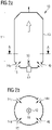
- figure 1 shows schematically an embodiment of a device according to the invention for the direct reduction 1 of metal oxides 2 by means of a reducing gas.
- reformer gas is produced by catalytic reforming of hydrocarbon-containing gas 4.
- the reformer gas is discharged from the catalytic reformer 3 through the reformer gas line 5 .
- a precursor gas line 6 extends from the reformer gas line 5 .
- the precursor gas line 6 includes an electric gas heater 7.
- the precursor gas is based on the reformer gas and is heated in the electrical gas heating device 7 by means of electrical energy.
- the precursor gas line 6 opens—in the flow direction away from the reformer behind the electric gas heating device 7—into a reducing gas line 8. This itself opens into a reduction unit 9, and reducing gas is introduced into the reduction unit 9 via it.
- the metal oxides are in the reduction unit 9;
- the reduction unit 9 is a reduction shaft, in which there is a solid bed of material comprising the metal oxides.
- the metal oxides 2 are directly reduced by means of the reducing gas flowing through the material bed.
- the reformer gas line 5 can also additionally have an opening into the reducing gas line 8; this is shown with a branch of reformer gas line 5 drawn in dashed lines. In this way, some reformer gas can be guided past the gas heating device 7 in the bypass and added to the heated precursor gas as additional gas.
- FIG. 1 In principle, further precursor gas lines could also be present in FIG. 1 for the purpose of preparing the reducing gas; this is not shown separately for the sake of clarity.
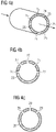
- FIGS 2a and 2b 12 show longitudinal and cross-sections through one embodiment of a portion of an electric gas heater 10 having a heating chamber 11 with a plasma torch 12.
- FIG. The plasma torch 12 is arranged in the center of the heating chamber 11 . This is made in cross-section along line AA Figure 2a in Figure 2b good to see.
- the cylindrical, round heating chamber in the example shown 11 is delimited by the longitudinal wall 13 of the heating chamber.
- Precursor gas is - shown as an arrow - introduced into the heating chamber 11 through the introduction openings 14a, 14b, 14c, 14d. Heated gas--represented by a block arrow--is discharged from the heating chamber 11 through a discharge opening, not shown separately--represented by an arrow.
- the precursor gas is introduced into the heating chamber 11 between the longitudinal wall 13 of the heating chamber and the plasma torch 12 .
- the flow of precursor gas 15 shown from the inlet opening 14a is thus located between the plasma 16 and the longitudinal wall 13 of the heating chamber.
- figure 3 12 shows a section through one embodiment of a portion of an electric gas heater 17 having a heating chamber 18 with a plasma torch 19.
- the heating chamber 18 is essentially cylindrical, with the plasma torch 19 lying essentially along the cylinder axis 20 .
- Precursor gas 22 is introduced tangentially into the heating chamber 18 through an introduction device 21 with an inlet opening and, after introduction, flows around the plasma torch 19 to the discharge opening 23.
- the cylinder axis 20 runs through the discharge opening 23 for discharging the heated gas.
- Several such heating chambers could also be used each with a plasma torch in the electric gas heating device.
- FIGS. 4 a - i show variants of the arrangement of plasma torches in a heating chamber of a gas heating device, in which there are several plasma torches.
- possible arrangement forms are ring-shaped, semi-circular or part-circle arranged radially around the longitudinal axis of the heating chamber, which in the Figures 4a, 4b, 4c is shown.
- Figure 4a shows an oblique view in a section through a cylindrical heating chamber 24 perpendicular to the longitudinal axis - that of the flow direction of the gas to be heated, with arrows indicated corresponds to - how ring-shaped several openings 25 are present for mounting plasma torches.
- the longitudinal axis of the plasma burners can, for example, be perpendicular or inclined to the longitudinal axis of the heating chamber 24 .
- Figure 4b shows in a section through a cylindrical heating chamber 26 perpendicular to the longitudinal axis - which corresponds to the direction of flow of the gas to be heated - how semicircular several openings 27 are present for mounting plasma torches.
- Figure 4c shows in a section through a cylindrical heating chamber 28 perpendicular to the longitudinal axis - which corresponds to the direction of flow of the gas to be heated - how semicircular there are several openings 29 for mounting plasma torches.
- Figure 4d shows a longitudinal section through a section of a heating chamber as in FIG Figure 4a how to install multiple rings of plasma torches;
- the openings 25 for assembly, the longitudinal axis 30 of the heating chamber and the gas flow direction 31 are shown.
- Figure 4e shows this in a corresponding view for an arrangement in which there is only one plasma torch per position along the longitudinal axis.
- Figure 4f shows in a corresponding view an example of how the plasma torches can be oriented with respect to the longitudinal axis.
- the arrows indicate that the plasma torches are inclined to the longitudinal axis.
- Figures 4g and 4h show in to the Figure 4a largely analogous view that the plasma torches indicated by arrows can be aimed at the center of the gas flow - in Figure 4g shown -, or practically tangential to the gas flow - in Figure 4h shown.
- the directional vector of the entering plasma torch flow - the directions of the arrows in the Figures 4g and 4h corresponds - can therefore be at least partially axial and / or at least partially tangential to the flow of gas from the gas inlet port to the gas outlet port.
- Figure 4i is shown schematically in a section perpendicular to the longitudinal axis of a variant of a heating chamber 32, such as the gas flow 33 to be heated between the plasma torch 34 and wall of the heating chamber 32 is introduced.
- Figure 5a shows a longitudinal section through a heating chamber 35, which includes a cylindrical part inlet part 36 with inlet opening 37 and a conical part outlet part 38 with outlet opening 39.
- the hydraulic diameter of the inlet opening 37 is 45% of the diameter of the inlet part.
- the ratio of the diameter of the inlet opening 37 to the radius of the inlet part 36 is 90%.
- the angle ⁇ of the heating chamber side wall of the discharge part to the longitudinal axis 40 is 35°.
- the plasma torch 41 is arranged centrally in the cover part 42, and a carrier gas line 43 for supplying carrier gas is also shown.
- the inlet opening is not symmetrical - ie asymmetrical - arranged to the longitudinal axis of the heating chamber.
- the flow of precursor gas that is introduced can flow in a spiral shape along the longitudinal wall of the heating chamber—in the inlet part and in the outlet part; the current is not introduced radially towards the longitudinal axis, but tangentially to the longitudinal wall of the heating chamber.
- Figure 5b shows a view of the in Figure 5a shown device from above. Analogous to Figure 5a outlines of variants of the inlet opening are also drawn in with dotted and dashed lines.
- Figure 6a and 6b show in to Figure 5a and 5b largely analogous views of an embodiment in which the introduction opening 45 on the introduction part 44 compared to Figure 5a is offset laterally.
- the gas flow to be heated is introduced into the cylindrical part, introduction part 44 spiral.
- FIG. 12 schematically shows, by means of a section along FF′, seen from above, how the inlet is drawn spirally around the cylindrical inlet part 44.
- FIG. The dashed line shows the outline of the edge C in the area where the inlet opening opens into the cylindrical inlet part.
- the helical portion could also extend less or more; it could also follow the shape of the entire lead-in portion of the spiral dictated by the lead-in 46.
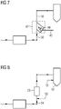
- figure 7 shows analogous to figure 1 , How in the electric gas heater 47 a plasma torch 48, whose plasma is generated with electrical energy using carrier gas from the carrier gas line 49, in the gas heater 47 the precursor gas reformer gas in the precursor gas line 50 is heated. The electrical energy is introduced into the precursor gas by means of a plasma.
- figure 8 shows largely analogous to figure 1 an embodiment of a device according to the invention, in which an additional reducing gas line 51 for introducing additional reducing gas into the reduction unit 52 is present.
- the optional addition of natural gas 53 to the precursor gas line 54 upstream of the electric gas heating device 55 is also shown in dashed lines.
- a precursor gas which is a mixture of natural gas 53 and reformer gas, is heated; this precursor gas is based on reformer gas.
Landscapes
- Engineering & Computer Science (AREA)
- Chemical & Material Sciences (AREA)
- Manufacturing & Machinery (AREA)
- Materials Engineering (AREA)
- Metallurgy (AREA)
- Organic Chemistry (AREA)
- Hydrogen, Water And Hydrids (AREA)
- Manufacture Of Iron (AREA)
- Manufacture And Refinement Of Metals (AREA)
Description
Die Erfindung betrifft ein Verfahren zur Direktreduktion von Metalloxiden unter Verwendung eines Reduktionsgases, das auf zumindest einem Vorläufergas basiert, wobei zumindest ein Vorläufergas auf durch katalytische Reformierung von kohlenwasserstoffhaltigem Gas in einem Reformer erhaltenem Reformergas basiert. Sie betrifft auch eine Vorrichtung zur Direktreduktion von Metalloxiden mittels eines Reduktionsgases, umfassend einen katalytischen Reformer zur Herstellung eines Reformergases, eine Reformergasleitung zur Ausleitung von Reformergas aus dem katalytischen Reformer, ein Reduktionsaggregat, und eine Reduktionsgasleitung zur Einleitung von Reduktionsgas in das Reduktionsaggregat.The invention relates to a method for the direct reduction of metal oxides using a reducing gas which is based on at least one precursor gas, at least one precursor gas being based on reformer gas obtained by catalytic reforming of hydrocarbon-containing gas in a reformer. It also relates to a device for the direct reduction of metal oxides by means of a reducing gas, comprising a catalytic reformer for producing a reformer gas, a reformer gas line for discharging reformer gas from the catalytic reformer, a reduction unit, and a reducing gas line for introducing reducing gas into the reduction unit.
Herstellung von Metallen mittels Direktreduktion von Metalloxiden durch ein mittels Reformierung von kohlenwasserstoffhaltigen Gasen hergestelltes Reduktionsgas ist bekannt - beispielsweise ist das MIDREX®-Verfahren zur Direktreduktion von Eisenoxiden wirtschaftlich sehr bedeutend. Das Reduktionsgas wird dabei zwecks Direktreduktion in einen mit dem Metalloxid befüllten Reduktionsschacht eingeleitet und reagiert beim Durchströmen mit der Füllung. Die Reaktionskinetik für die Reduktion ist bei höherer Temperatur des Reduktionsgases günstiger - um bei einer vergleichsweise tieferen Einleitungstemperatur des Reduktionsgases eine gewünschte Anlagenleistung zu erreichen, müsste bei einem gegebenem Reduktionsschacht die spezifische Reduktionsgasmenge und eventuell der Anlagendruck erhöht werden, oder leichter reduzierbare Rohstoffe - beispielsweise Pellets - müssten verwendet werden, welche mit bedeutend höheren Kosten verbunden sind. Dem maximal einstellbaren Anlagendruck und der maximal einleitbaren spezifischen Reduktionsgasmenge sind jedoch Grenzen gesetzt, da ansonsten der Druckverlust zu hoch wird und zu einer Behinderung des Materialflußes führt. Zur Einstellung einer gewünschten Einleitungstemperatur muss von dem Temperaturniveau des den Reformer verlassenden Gases ausgegangen werden. Einer Steigerung dieses Temperaturniveaus sind jedoch Temperaturgrenzen des Reformers gesetzt.The production of metals by direct reduction of metal oxides by means of a reducing gas produced by reforming gases containing hydrocarbons is known - for example the MIDREX® process for the direct reduction of iron oxides is economically very important. For the purpose of direct reduction, the reducing gas is introduced into a reduction shaft filled with the metal oxide and reacts with the filling as it flows through. The reaction kinetics for the reduction are more favorable at a higher temperature of the reducing gas - in order to achieve a desired system output at a comparatively lower introduction temperature of the reducing gas, the specific The amount of reducing gas and possibly the system pressure must be increased, or raw materials that can be reduced more easily - for example pellets - would have to be used, which are associated with significantly higher costs. However, there are limits to the maximum system pressure that can be set and the maximum specific amount of reducing gas that can be introduced, since otherwise the pressure loss would be too high and would impede the flow of material. In order to set a desired inlet temperature, the temperature level of the gas leaving the reformer must be taken as a starting point. However, temperature limits of the reformer are set for an increase in this temperature level.
Um die Produktionsleistung trotz solcher Randbedingungen von Reduktionsschacht und Reformer anheben zu können, werden oft zwischen Reformer und Reduktionsschacht Maßnahmen zur Erhöhung der Einleitungstemperatur durchgeführt. Beispielsweise ist es bekannt, durch Einbringung von Sauerstoff in den Gasstrom temperaturerhöhende Verbrennung von reduzierenden Bestandteilen einzuleiten. Das hat jedoch den Nachteil, dass die Reduktionskraft des eingeleiteten Reduktionsgases abnimmt, und sich der spezifische Energieverbrauch der Direktreduktion insgesamt erhöht. Temperaturerhöhung durch Verbrennung von zusätzlichem Erdgas mit Sauerstoff führt zwar zu einer gleichzeitigen Erhöhung der Reduktionsgasmenge, kann aber Probleme durch Veränderung der Reduktionsgaszusammensetzung, Rußbildung, ungünstige Gasströmungen verursachen, und muss genau kontrolliert werden.In order to be able to increase the production capacity despite such boundary conditions of the reduction shaft and reformer, measures to increase the inlet temperature are often carried out between the reformer and the reduction shaft. For example, it is known to initiate temperature-increasing combustion of reducing components by introducing oxygen into the gas stream. However, this has the disadvantage that the reducing power of the introduced reducing gas decreases and the specific energy consumption of the direct reduction increases overall. Temperature increase by burning additional natural gas with oxygen leads to a simultaneous increase in the amount of reducing gas, but can cause problems due to changes in the reducing gas composition, soot formation, unfavorable gas flows, and must be carefully controlled.
Es sollen ein Verfahren und eine Vorrichtung vorgestellt werden, die eine Erhöhung der Einleitungstemperatur und Steigerung der Produktionsleistung ohne die Nachteile bekannter Verfahren erlauben.A method and a device are to be presented which allow the introduction temperature to be increased and the production output to be increased without the disadvantages of known methods.
Diese Aufgabe wird gelöst durch ein Verfahren nach Anspruch 1.This object is achieved by a method according to claim 1.
Reduktionsgas ist ein Gas, das in ein die zu reduzierenden Metalloxide enthaltendes Reduktionsaggregat - beispielsweise ein Reduktionsschacht oder ein Wirbelschichtaggregat - eingeleitet wird, um dort die Metalloxide zumindest teilweise zu reduzieren.Reducing gas is a gas that is introduced into a reduction unit containing the metal oxides to be reduced—for example a reduction shaft or a fluidized bed unit—in order to at least partially reduce the metal oxides there.
Ein Reduktionsgas, das auf zumindest einem Vorläufergas basiert, wobei zumindest ein Vorläufergas auf durch katalytische Reformierung von kohlenwasserstoffhaltigem Gas in einem Reformer erhaltenem Reformergas basiert und bei der Zubereitung des Reduktionsgases mittels elektrischer Energie aufgeheizt wird, wird beispielsweise Reduktionsgas A genannt. Zur Direktreduktion kann entweder nur Reduktionsgas A verwendet werden, oder es können zusätzlich zu Reduktionsgas A noch ein weiteres Reduktionsgas oder mehrere weitere Reduktionsgase - auch genannt Zusatzreduktionsgase - verwendet werden - dabei müssen die für Reduktionsgas A genannten Bedingungen für die weiteren Reduktionsgase nicht gelten.A reducing gas based on at least one precursor gas, wherein at least one precursor gas is based on reformer gas obtained by catalytic reforming of hydrocarbon-containing gas in a reformer and is heated by means of electrical energy during the preparation of the reducing gas, is called reducing gas A, for example. Either only reducing gas A can be used for direct reduction, or in addition to reducing gas A, another reducing gas or several further reducing gases - also called additional reducing gases - can be used - the conditions specified for reducing gas A do not have to apply to the further reducing gases.
Als katalytische Reformierung bezeichnet man die Umsetzung von kohlenwasserstoffhältigen Stoffen, insbesondere Gasen, mit H2O und CO2 in Gegenwart eines Katalysators in einem katalytischen Reformer zur Herstellung von H2- und COhaltigem Gas, welches im Rahmen dieser Anmeldung Reformergas genannt wird.Catalytic reforming is the reaction of hydrocarbon-containing substances, in particular gases, with H 2 O and CO 2 in the presence of a catalyst in one catalytic reformer for the production of H 2 - and CO-containing gas, which is called reformer gas in this application.
Reformergas tritt aus dem Reformer in der Regel mit einer Austrittstemperatur im Bereich von 850°C bis 970°C aus.Reformer gas generally exits the reformer at an exit temperature in the range from 850°C to 970°C.
Die Metalloxide umfassen bevorzugterweise Eisenoxide, besonders bevorzugt sind sie Eisenoxide. Eisenoxide sind beispielsweise hämatitische oder magnetitische Erze, oder Agglomerate wie beispielsweise Eisenerzpellets.The metal oxides preferably include iron oxides, more preferably they are iron oxides. Iron oxides are, for example, hematitic or magnetitic ores, or agglomerates such as iron ore pellets.
Es wird unter Verwendung eines Reduktionsgases reduziert, das auf zumindest einem Vorläufergas basiert - bei der Zubereitung des Reduktionsgases wird also zumindest ein Vorläufergas verwendet. Zumindest ein Vorläufergas basiert auf dem Reformergas; es können auch mehrere Vorläufergase auf dem Reformergas basieren. Bei der Zubereitung dieses Reduktionsgases wird zumindest ein Vorläufergas mittels elektrischer Energie aufgeheizt. Erfindungsgemäß wird zumindest ein auf Reformergas basierendes Vorläufergas mittels elektrischer Energie aufgeheizt.It is reduced using a reducing gas that is based on at least one precursor gas—that is, at least one precursor gas is used in the preparation of the reducing gas. At least one precursor gas is based on the reformer gas; several precursor gases can also be based on the reformer gas. During the preparation of this reducing gas, at least one precursor gas is heated using electrical energy. According to the invention, at least one precursor gas based on reformer gas is heated by means of electrical energy.
- eine nicht reformierte Teilmenge eines für die Reformierung vorgesehenen kohlenwasserstoffhaltigen Gases,
- Wasserstoff H2,
- Kohlenmonoxid CO,
- kohlenwasserstoffhaltige Gase, wie beispielsweise auf Basis LPG, PAH, BTEX, CH4, CmHn, Erdgas, und/oder eine Mischung aus diesen Gasen,
- ein aus einem Reduktionsaggregat, in dem die Metalloxide reduziert werden, abgezogenes Topgas, oder aus dem bei Durchführung des erfindungsgemäßen Verfahrens aus dem Reduktionsaggregat, in dem die Metalloxide direktreduziert werden, abgezogenes Topgas,
- Inertgase, wie beispielsweise N2, Ar,
oder eine Mischung aus mehreren dieser beispielhaft angeführten Gase, oder eine Mischung eines anderen Gases mit einem oder mehreren dieser beispielhaft angeführten Gase. Zumindest ein weiteres Vorläufergas enthält gegenüber Metalloxiden, bevorzugt Eisenoxiden, reduzierend wirkende Gaskomponenten, oder besteht aus solchen Gaskomponenten. Weiteres Vorläufergas kann aber auch gegenüber Metalloxiden inerte Gaskomponenten, oder aufkohlend wirkende Gaskomponenten enthalten oder aus solchen Gaskomponenten bestehen.
- a non-reformed portion of a hydrocarbon-containing gas intended for reforming,
- hydrogen H2 ,
- carbon monoxide CO,
- Gases containing hydrocarbons, such as those based on LPG, PAH, BTEX, CH 4 , CmHn, natural gas, and/or a mixture of these gases,
- a top gas drawn off from a reduction unit in which the metal oxides are reduced, or from the top gas drawn off from the reduction unit in which the metal oxides are directly reduced when the method according to the invention is carried out,
- Inert gases such as N 2 , Ar,
or a mixture of several of these exemplified gases, or a mixture of another gas with one or more of these exemplified gases. At least one further precursor gas contains gas components that have a reducing effect compared to metal oxides, preferably iron oxides, or consists of such gas components. However, further precursor gas can also contain gas components which are inert towards metal oxides, or gas components which have a carburizing effect, or consist of such gas components.
Das Reformergas ist das bei katalytischer Reformierung von kohlenwasserstoffhaltigem Gas - wie beispielsweise Erdgas, Methan, liquified natural gas LNG, liquified petroleum gas LPG, Koksofengas COG, Biogas; es kann ein reines Gas sein oder ein Gasgemisch - in einem Reformer erhaltene Produkt. Auf dem Reformergas basierendes Vorläufergas kann zumindest eine Teilmenge des Reformergases umfassen, es kann auch das gesamte Reformergas umfassen. Auf dem Reformergas basierendes Vorläufergas kann auch aus einer Teilmenge des Reformergases oder dem gesamten Reformergas bestehen. Auf dem Reformergas basierendes Vorläufergas kann auch durch Veränderung des Reformergases hergestellt werden, beispielsweise durch Veränderung von Druck, Temperatur, Zusammensetzung. Die Zusammensetzung kann beispielsweise durch Zufuhr anderer Gase - wie beispielsweise Erdgas - verändert werden, durch Abtrennung von Gaskomponenten, durch Reaktionen im Reformergas - solche Reaktionen können beispielsweise durch Druck- oder Temperaturänderung beziehungsweise durch Zufuhr anderer Gase hervorgerufen werden.The reformer gas is the catalytic reforming of hydrocarbon-containing gas - such as natural gas, methane, liquefied natural gas LNG, liquefied petroleum gas LPG, coke oven gas COG, biogas; it can be a pure gas or a mixture of gases - product obtained in a reformer. Precursor gas based on the reformer gas can comprise at least a subset of the reformer gas, it can also comprise the entire reformer gas. Precursor gas based on the reformer gas can also consist of a subset of the reformer gas or the entire reformer gas. Precursor gas based on the reformer gas can also be produced by changing the reformer gas, for example by changing the pressure, temperature, composition. The composition can be changed, for example, by supplying other gases - such as natural gas - by separating gas components, by reactions in the reformer gas - such reactions can be caused, for example, by pressure or temperature changes or by supplying other gases.
Erfindungsgemäß wird bei der Zubereitung des Reduktionsgases zumindest ein auf Reformergas basierendes Vorläufergas mittels elektrischer Energie aufgeheizt.According to the invention, at least one precursor gas based on reformer gas is heated by means of electrical energy during the preparation of the reducing gas.
Das hat den Vorteil, dass zur Temperaturerhöhung kein Sauerstoff oder Verbrennungsprodukte eingebracht werden, und damit verbundene Probleme hinsichtlich Oxidation reduzierender Gaskomponenten oder Änderung der Gaszusammensetzung vermieden werden. Im Vergleich zu sauerstoffbasierten Verfahren zur Temperaturerhöhung kann die Leistung einer Direktreduktionsanlage deutlich vergrößert werden, da keine reduzierenden Gaskomponenten zur Temperaturerhöhung verbraucht werden. Je niedriger die Temperatur des Vorläufergases ist, desto ausgeprägter ist dabei der Vorteil einer elektrischen Aufheizung: bei einer größeren Differenz zu einer angestrebten Endtemperatur muss bei niedrigerer Vorläufergastemperatur mehr Gas verbrannt werden, um durch die Verbrennung die Temperatur entsprechend zu erhöhen - es würden also mehr reduzierende Gaskomponenten im Vorläufergas oxidiert werden, was das Reduktionspotential für Metalloxide verringert.This has the advantage that no oxygen or combustion products are introduced to increase the temperature, and associated problems with regard to oxidation of reducing gas components or changes in the gas composition are avoided. Compared to oxygen-based processes for increasing the temperature, the performance of a direct reduction system can be significantly increased, since no reducing gas components are used to increase the temperature. The lower the temperature of the precursor gas, the more pronounced is the advantage of electrical heating: with a larger difference to a desired final temperature, more gas has to be burned at a lower precursor gas temperature in order to increase the temperature accordingly through combustion - so there would be more reducing Gas components in the precursor gas are oxidized, reducing the reduction potential for metal oxides.
Auch die Sicherheit wird erhöht, weil sich keine explosionsfähigen Mischungen mit Sauerstoff bilden können. Die elektrische Aufheizung kann auch dazu führen, dass chemische Reaktionen rascher ablaufen und sich neue Gasgleichgewichte einstellen. Gemäß der Erfindung sind Plasma oder Radikale gebildet, die besonders reaktiv sind; gegebenenfalls wird dabei auch die Zusammensetzung eines Plasma-Trägergases durch chemische Reaktionen und/oder Moleküldissoziation verändert.Safety is also increased because no explosive mixtures with oxygen can form. Electrical heating can also lead to chemical reactions taking place more quickly and new gas equilibria being established. According to the invention, plasma or radicals are formed which are particularly reactive; where appropriate, the composition of a plasma carrier gas is also changed by chemical reactions and/or molecular dissociation.
Optional können zusätzlich auch ein weiteres Vorläufergas oder mehrere weitere Vorläufergase mittels elektrischer Energie aufgeheizt werden.Optionally, a further precursor gas or several further precursor gases can also be heated by means of electrical energy.
Bevorzugt wird durch die elektrische Energie das auf Reformergas basierende Vorläufergas auf eine Temperatur aufgeheizt, die in einem Ausmaß von bis zu 200°C, bevorzugt bis zu 100°C, besonders bevorzugt bis zu 70°C, über dessen Austrittstemperatur aus dem Reformer liegt. Beispielsweise wird auf Reformergas basierendes Vorläufergas, das mit einer Austrittstemperatur von 900°C aus dem Reformer austritt, durch die elektrische Energie auf 970°C erhitzt.The precursor gas based on reformer gas is preferably heated by the electrical energy to a temperature which is to an extent of up to 200° C., preferably up to 100° C., particularly preferably up to 70° C., above that Outlet temperature from the reformer is. For example, precursor gas based on reformer gas, which exits the reformer at an exit temperature of 900°C, is heated to 970°C by the electrical energy.
Je größer die durch Aufheizung mittels elektrischer Energie hervorzurufende Temperaturerhöhung ist, desto unwirtschaftlicher wird diese Aufheizung im Vergleich zu einer übermäßigen Temperaturerhöhung im Reformer; daher ist eine Obergrenze von 200°C, bevorzugt bis zu 100°C, besonders bevorzugt bis zu 70°C, Temperaturerhöhung für die Aufheizung vorgesehen.The greater the temperature increase to be brought about by heating by means of electrical energy, the more uneconomical this heating becomes in comparison to an excessive temperature increase in the reformer; therefore, an upper limit of 200° C., preferably up to 100° C., particularly preferably up to 70° C., is provided for the temperature increase for the heating.
Bevorzugt wird das eine weitere Vorläufergas oder die mehreren weiteren Vorläufergase, die durch elektrische Energie aufgeheizt werden, dabei auf eine Temperatur aufgeheizt, die in einem Ausmaß von bis zu 200 °C über der Austrittstemperatur von Reformergas aus dem Reformer liegt.The one further precursor gas or the several further precursor gases that are heated by electrical energy are preferably heated to a temperature which is up to 200° C. above the exit temperature of reformer gas from the reformer.
Vom Austritt aus dem Reformer bis zur Einleitung in ein die zu reduzierenden Metalloxide enthaltendes Reduktionsaggregat kann Wärme an die Umgebung verloren gehen. Einspeisung von anderen Gasen - beispielsweise Zusatzgas oder weiteres Vorläufergas - mit gegenüber Reformergas geringerer Temperatur, die gegebenenfalls zur Herstellung des Reduktionsgases erfolgt, führt zu geringerer Temperatur des Reduktionsgases. Durch Aufheizung mittels elektrischer Energie kann ein Wärmeverlust an die Umgebung beziehungsweise Temperaturerniedrigung infolge Einspeisung zumindest teilweise kompensiert werden, und dem Reduktionsgas die gewünschte Temperatur für den Eintritt in das die zu reduzierenden Metalloxide enthaltende Reduktionsaggregat gegeben werden.From leaving the reformer to being introduced into a reduction unit containing the metal oxides to be reduced, heat can be lost to the environment. Feeding in other gases--for example additional gas or further precursor gas--with a lower temperature than reformer gas, which may be carried out to produce the reducing gas, leads to a lower temperature of the reducing gas. By heating with electrical energy, a heat loss to the environment or temperature reduction due to feeding can be at least partially compensated, and the reducing gas can be given the desired temperature for entry into the reduction unit containing the metal oxides to be reduced.
Damit das Reduktionsgas beim Einleiten zumindest nicht wesentlich kühler als die Austrittstemperatur aus dem Reformer ist, ist Temperaturerhöhung um zumindest 10°C, besonders bevorzugt zumindest 20°C, ganz besonders bevorzugt zumindest 30°C, und überaus bevorzugt zumindest 50°C über die Austrittstemperatur bevorzugt.So that the reducing gas is at least not significantly cooler than the exit temperature from the reformer when it is introduced, the temperature must be increased by at least 10° C., particularly preferably at least 20° C., very particularly preferably at least 30° C., and extremely preferably at least 50° C. above the exit temperature preferred.
Bevorzugt wird das eine weitere Vorläufergas oder die mehreren weiteren Vorläufergase, die durch elektrische Energie aufgeheizt werden, dabei auf eine Temperatur aufgeheizt, die in einem Ausmaß von zumindest 10°C, besonders bevorzugt zumindest 20°C, ganz besonders bevorzugt zumindest 30°C, und überaus bevorzugt zumindest 50°C über der Austrittstemperatur bevorzugt.The one further precursor gas or several further precursor gases that are heated by electrical energy are preferably heated to a temperature that is at least 10° C., particularly preferably at least 20° C., very particularly preferably at least 30° C. and most preferably at least 50°C above the outlet temperature.
Bei elektrischer Aufheizung von auf dem Reformergas basierenden Vorläufergas nach Reformierung, beziehungsweise bei elektrischer Aufheizung eines anderen Vorläufergases, kann der Reformerbetrieb optimiert werden, ohne dass damit gegebenenfalls verbundene geringere Temperatur des Reformergases sich auf die Produktivität der Direktreduktion negativ auswirkt. Für verbesserte Produktivität der Direktreduktion günstige Änderungen der Temperatur und auch der Zusammensetzung des Reduktionsgases können nach der Reformierung durchgeführt werden. Der Reformer muss also beispielsweise nicht jenseits von für seine Funktion und günstigen Standzeiten optimalen Temperaturen betrieben werden, um eine gewünschte Reduktionsgastemperatur oder -zusammensetzung sicherzustellen. Stattdessen kann der Reformer schonend betrieben werden, was seine Lebensdauer, im speziellen der Reformerrohre, aufgrund geringeren Kriechens in Längs- und Durchmesserrichtung der Reformerrohre, beziehungsweise die Lebensdauer des Katalysators im Reformer verlängert. Das steigert die Wirtschaftlichkeit des Verfahrens zur Direktreduktion. Vermindertes Temperaturniveau im Reformer führt auch zu verminderter Temperatur des Reformerabgases und vermindertem Brennstoffbedarf; der damit verbundene geringere Energieverlust des Verfahrens steigert die Wirtschaftlichkeit.With electrical heating of the precursor gas based on the reformer gas after reforming, or with electrical heating of another precursor gas, the reformer operation can be optimized without the associated lower temperature of the reformer gas having a negative effect on the productivity of the direct reduction. Changes in the temperature and also in the composition of the reducing gas favorable for improved productivity of the direct reduction can be carried out after the reforming. For example, the reformer does not have to be operated beyond temperatures that are optimal for its function and favorable service life in order to ensure a desired reducing gas temperature or composition. Instead, the reformer can be operated carefully, which extends its service life, in particular the reformer tubes, due to less creeping in the longitudinal and diameter direction of the reformer tubes, or the service life of the catalyst in the reformer. This increases the efficiency of the direct reduction process. A reduced temperature level in the reformer also leads to a reduced temperature of the reformer exhaust gas and a reduced fuel requirement; the associated lower energy loss of the process increases the cost-effectiveness.
Schonende Fahrweise eines katalytischen Reformers bei vermindertem Temperaturniveau kann zu einer eine optimale Direktreduktion nicht unterstützenden Zusammensetzung des Reformergases führen; speziell hinsichtlich CH4-Schlupf und CO2-Gehalt im Reformergas.Gentle operation of a catalytic reformer at a reduced temperature level can lead to a composition of the reformer gas that does not support optimal direct reduction; specifically with regard to CH 4 slip and CO 2 content in the reformer gas.
Durch Aufheizung mittels elektrischer Energie kann beispielsweise die - aufgrund von CH4-Schlupf und damit verbundenem höheren CH4-Gehalt im Reduktionsgas - verminderte Leistung bei der Reduktion kompensiert werden. Elektrische Aufheizung für ein solches Reformergas hat den Vorteil, dass das Reduktionspotential nicht auch noch durch Umsetzung reduzierender Gaskomponenten zwecks Aufheizung vermindert wird.By heating by means of electrical energy, for example, the reduced output during the reduction—due to CH 4 slip and the associated higher CH 4 content in the reduction gas—can be compensated for. Electrical heating for such a reformer gas has the advantage that the reduction potential is not also reduced by the conversion of reducing gas components for the purpose of heating.
Ebenso kann alterungsbedingte Degradierung beziehungsweise Deaktivierung des Katalysators im Reformer durch die elektrische Aufheizung teilweise kompensiert werden, und dadurch die Notwendigkeit von aufwändigem und teurem Austausch des Katalysatormaterials hinausgezögert werden. Zudem kann mittels elektrischer Aufheizung auf Temperaturen aufgeheizt werden, die bei Aufheizung im Reformer nicht erreichbar wären.Likewise, aging-related degradation or deactivation of the catalyst in the reformer can be partially compensated for by the electrical heating, thereby delaying the need for complex and expensive replacement of the catalyst material. In addition, electrical heating can be used to heat up to temperatures that would not be achievable with heating in the reformer.
Vorteilhaft ist es auch, dass durch die Entkopplung der Temperatur des Reduktionsgases von der Temperatur des Reformergases - und indirekt dadurch gegebenenfalls auch Entkopplung der Zusammensetzung des Reduktionsgases von der Zusammensetzung des Reformergases - einfach und schnell die beste Temperatur für die jeweils vorliegenden Metalloxide und die aktuelle Coatingmenge eingestellt werden kann. Der Regelbereich der elektrischen Aufheizung ist größer und die Regelung ist schneller im Vergleich zu einer Beeinflussung im Reformer. Der Betrieb der Reformierung und der Betrieb der Direktreduktion können so unabhängig voneinander optimiert werden, was das Verfahren insgesamt wirtschaftlicher macht. Im Vergleich zu Erhitzung mittels Verbrennung mit partieller Oxidation ist elektrische Erhitzung schneller und genauer regelbar, da nicht auf Verbrennungsreaktionen Rücksicht genommen werden muss. Im Vergleich zu Erhitzung mittels indirekter Aufheizung über Wärmetauscher ist elektrische Erhitzung schneller und genauer regelbar.It is also advantageous that by decoupling the temperature of the reducing gas from the temperature of the reformer gas - and indirectly thereby possibly also decoupling the composition of the reducing gas from the composition of the reformer gas - the best temperature for the metal oxides present in each case and the current coating quantity can be easily and quickly determined can be adjusted. The control range of the electrical heating is larger and the control is faster compared to an influence in the reformer. The operation of the reforming and the operation of the direct reduction can thus be optimized independently of one another, which makes the process more economical overall. Compared to heating by means of combustion with partial oxidation, electrical heating can be controlled more quickly and precisely, since combustion reactions do not have to be taken into account. Compared to heating by means of indirect heating via heat exchangers, electrical heating is faster and can be controlled more precisely.
Speziell bei Inbetriebnahme einer Direktreduktionsanlage zur Durchführung des erfindungsgemäßen Verfahrens ist die erfindungsgemäße elektrische Aufheizung günstig. Sie eröffnet die Möglichkeit, in einem Reduktionsgas, das nur oder auch auf einem Reformergas basiert, in dem noch wenige Bestandteile reformiert sind - weil der Reformer bei der Inbetriebnahme noch nicht in vollem Umfang arbeitet -, durch schnell regelbare Temperaturerhöhung in-situ-Reformierung vor und/oder nach Kontakt mit den Metalloxiden zu begünstigen.The electrical heating according to the invention is advantageous especially when a direct reduction plant is put into operation for carrying out the method according to the invention. It opens up the possibility of in-situ reforming in a reducing gas that is based only or also on a reformer gas, in which only a few components are reformed - because the reformer is not yet fully operational when it is put into operation - by means of a quickly controllable temperature increase and/or after contact with the metal oxides.
Nach einer Variante wird zumindest eine Teilmenge der elektrischen Energie direkt in das mittels elektrischer Energie aufzuheizende Vorläufergas eingebracht, beispielsweise mittels Widerstandsheizung mit Heizspirale, Lichtbogen zwischen Elektroden. Direkte Einbringung hat den Vorteil, dass der Wirkungsgrad sehr hoch ist. Das hat auch den Vorteil, dass bei der Einbringung der Energie stofflich nichts hinzufügt wird. Einfluss auf die stoffliche Zusammensetzung des Reduktionsgases kann bestehen, da der Energieeintrag die Kinetik chemischer Reaktionen von im Vorläufergas vorhandenen Komponenten miteinander beeinflusst, beziehungsweise beispielsweise an Elektrodenoberflächen Umsetzungen von im Vorläufergas vorhandenen Komponenten ablaufen.According to one variant, at least a portion of the electrical energy is introduced directly into the precursor gas to be heated by means of electrical energy, for example by means of resistance heating with a heating spiral, arc between electrodes. Direct introduction has the advantage that the efficiency is very high. This also has the advantage that nothing is added materially when the energy is introduced. The material composition of the reducing gas can be influenced because the energy input influences the kinetics of chemical reactions of components present in the precursor gas with one another, or, for example, reactions of components present in the precursor gas take place on electrode surfaces.
Nach der Erfindung gemäß Anspruch 1 wird zumindest eine Teilmenge der elektrischen Energie mittels Plasma, in das Vorläufergas eingebracht. Dabei kann die stoffliche Zusammensetzung des Reduktionsgases beeinflusst werden durch entsprechende Zusammensetzung des Trägermediums. Das Trägermedium kann Gas und/oder Flüssigkeit - beispielsweise Erdöl - und/oder Feststoff sein. Das Trägermedium ist bevorzugt frei von molekularem Sauerstoff. Wenn es sich um ein Plasma handelt, das mit einem Trägergas betrieben wird, ist es eine bevorzugte Variante, dass zumindest ein Teil des Trägergases ein Mitglied der folgenden Gruppe von Bestandteilen ist:
- ein durch katalytische Reformierung von kohlenwasserstoffhaltigem Gas in einem Reformer erhaltenes Reformergas,
- eine nicht reformierte Teilmenge eines für die Reformierung vorgesehenen kohlenwasserstoffhaltigen Gases,
- Wasserstoff H2,
- Kohlenmonoxid CO,
- kohlenwasserstoffhaltige Gase, wie beispielsweise auf Basis LPG, PAH, BTEX, CH4, CmHn, Erdgas, und/oder eine Mischung aus diesen Gasen,
- ein aus einem Reduktionsaggregat, in dem die Metalloxide reduziert werden, abgezogenes Topgas, oder aus dem bei Durchführung des erfindungsgemäßen Verfahrens aus dem Reduktionsaggregat, in dem die Metalloxide direktreduziert werden, abgezogenes Topgas,
- Inertgase, wie beispielsweise N2, Ar.
- a reformer gas obtained by catalytic reforming of hydrocarbon-containing gas in a reformer,
- a non-reformed portion of a hydrocarbon-containing gas intended for reforming,
- hydrogen H2 ,
- carbon monoxide CO,
- Gases containing hydrocarbons, such as those based on LPG, PAH, BTEX, CH 4 , CmHn, natural gas, and/or a mixture of these gases,
- a top gas drawn off from a reduction unit in which the metal oxides are reduced, or from the top gas drawn off from the reduction unit in which the metal oxides are directly reduced when the method according to the invention is carried out,
- Inert gases such as N2, Ar.
Das Trägergas wird nämlich durch die hohen Temperaturen im Plasmabrenner zumindest teilweise dissoziieren und bei der Mischung mit dem Vorläufergas normalerweise teilweise wieder rekombinieren. Durch geeignetes Wählen des Trägergases können zusätzliche reduzierende Gaskomponenten wie CO oder H2 entstehen. Einige Plasmakomponenten - wie beispielsweise atomarer Wasserstoff H - reagieren auch sehr schnell mit Metalloxid, bevorzugt Eisenoxid. Besonders bevorzugt sind Trägergase, welche nach der Mischung zusätzliche reduzierende Verbindungen nach der Rekombination erzeugen oder im Plasmazustand sehr schnell mit dem Metalloxid, bevorzugt Eisenoxid, reagieren.This is because the carrier gas will at least partially dissociate due to the high temperatures in the plasma torch and will normally partially recombine when mixed with the precursor gas. By suitably selecting the carrier gas, additional reducing gas components such as CO or H 2 can arise. Some plasma components - such as atomic hydrogen H - also react very quickly with metal oxide, preferably iron oxide. Particular preference is given to carrier gases which, after mixing, produce additional reducing compounds after recombination or which, in the plasma state, react very quickly with the metal oxide, preferably iron oxide.
Grundsätzlich kann ein Trägergas ein Prozessgas - Erdgas eingeschlossen - oder ein Abgas aus einem Verfahren zur Direktreduktion oder aus dem erfindungsgemäßen Verfahren zur Direktreduktion - beispielsweise Topgas aus dem Reduktionsaggregat, also beispielsweise einem Reduktionsschacht oder einem Wirbelschichtaggregat- sein, oder es kann ein Gas aus einer externen Gasquelle - beispielsweise ein Koksofengas COG, Biogas, LNG, Gas auf Basis LPG - sein, wobei diese Gase gekühlt oder vorgewärmt, gereinigte oder ungereinigt eingesetzt werden können. Es kommen in Frage H2- und/oder CO- und/oder CO2- und/oder H2O-haltige und/oder CH4-haltige Gase und/oder andere kohlenwasserstoffhaltige Gase, gekühlte oder vorgewärmte Gase, gereinigte oder ungereinigte Gase.In principle, a carrier gas can be a process gas - including natural gas - or an exhaust gas from a direct reduction process or from the direct reduction process according to the invention - for example top gas from the reduction unit, for example a reduction shaft or a fluidized bed unit - or it can be a gas from an external Gas source - for example a coke oven gas COG, biogas, LNG, gas on Based on LPG - these gases can be used cooled or preheated, cleaned or uncleaned. Gases containing H 2 and/or CO and/or CO 2 and/or H 2 O and/or CH 4 and/or other hydrocarbon-containing gases, cooled or preheated gases, cleaned or uncleaned gases are suitable .
Durch die Wahl des Trägermediums kann Einfluss auf die Zusammensetzung des Reduktionsgases ausgeübt werden, da das Trägermedium selbst auch Komponenten zum Reduktionsgas liefern kann. Beispielsweise kann ein gereinigtes Topgas alleine oder in Mischung mit anderen Trägermedien, beispielsweise Koksofengas COG, als Trägermedium genutzt werden. Temperaturen in einem Plasma sind in der Regel sehr hoch. Wenn Verbindungen, deren thermische Zerstörung erwünscht ist, Teil des Trägermediums sind, lässt sich einerseits der Nutzen ihrer thermischen Zerstörung ziehen. Andererseits können Zerstörungsprodukte als reduzierende Gaskomponenten, oder als Vorprodukte für reduzierende Gaskomponenten, des Reduktionsgases genutzt werden. Besonders vorteilhaft ist es auch, Verbindungen, die in einem Reformer schwierig zu reformieren sind, nicht dem Reformer zuzuführen, sondern als Bestandteil des Trägermediums zu nutzen, um Zerstörungsprodukte als reduzierende Gaskomponenten, oder als Vorprodukte für reduzierende Gaskomponenten des Reduktionsgases einer Nutzung zuzuführen. Es kann beispielsweise sein, dass Erdgas höhere Kohlenwasserstoffe beinhaltet, die vor Reformierung in einem Reformer abgetrennt werden müssen. Solche abgetrennten Komponenten können dann als Trägermedien oder Teile davon genutzt werden.The selection of the carrier medium can influence the composition of the reducing gas, since the carrier medium itself can also supply components for the reducing gas. For example, a cleaned top gas can be used alone or mixed with other carrier media, for example coke oven gas COG, as the carrier medium. Temperatures in a plasma are usually very high. On the one hand, if compounds whose thermal destruction is desired are part of the carrier medium, the benefit of their thermal destruction can be obtained. On the other hand, products of destruction can be used as reducing gas components, or as precursors for reducing gas components, of the reducing gas. It is also particularly advantageous not to feed compounds that are difficult to reform in a reformer to the reformer, but to use them as a component of the carrier medium in order to use destruction products as reducing gas components or as precursors for reducing gas components of the reducing gas. For example, natural gas may contain higher hydrocarbons that have to be separated off in a reformer before being reformed. Such separated components can then be used as carrier media or parts thereof.
Bevorzugt ist es, als Trägergas Gase beziehungsweise Gasmischungen zu verwenden, deren Einsatz Rußbildung vermeidet. Dazu wird das Verhältnis von kohlenstoffbeziehungsweise kohlenwasserstoffhaltigen Gasbestandteilen zu oxidierenden Gasbestandteilen, wie beispielsweise CO2, H2O, sowie die elektrische Leistung und die Größe der Trägermedien- beziehungsweise Gasströme entsprechend kontrolliert.It is preferred to use gases or gas mixtures as the carrier gas, the use of which avoids the formation of soot. For this purpose, the ratio of carbon or hydrocarbon-containing gas components to oxidizing gas components, such as CO 2 , H 2 O, and the electrical power and the size of the Carrier media or gas flows controlled accordingly.
Der hohe Bedarf elektrischer Energie zum Betrieb von Plasmabrennern würde erwarten lassen, dass Einsatz von Plasmabrennern zur elektrischen Aufheizung des Vorläufergases wirtschaftlich nicht tragbar ist. Es zeigt sich nun unerwarteterweise, dass sich auch bei elektrischer Aufheizung mittels Plasma bei der Verfahrensführung der Direktreduktion im höheren Temperaturbereich wirtschaftlich günstige Ergebnisse erzielen lassen.The high electrical energy requirement for the operation of plasma torches would lead one to expect that the use of plasma torches for the electrical heating of the precursor gas would not be economically viable. It has now unexpectedly turned out that economically favorable results can also be achieved with electrical heating by means of plasma when carrying out the direct reduction process in the higher temperature range.
Nach einer Variante wird für elektrische Aufheizung vorgesehenes Vorläufergas vor der Aufheizung mittels elektrischer Energie bereits auf andere Weise aufgeheizt, bevorzugt auf zumindest 700 °C, besonders bevorzugt auf zumindest 750 °C. Im Falle von Reformergas als Vorläufergas ist die elektrische Aufheizung also in Flussrichtung des Reformergases nach dem Reformer und nach einer anderen - nicht elektrischen - Aufheizmethode angeordnet, um beispielsweise die Temperaturbegrenzung dieser anderen Aufheizmethode zu umgehen oder die Lebensdauer/Wirtschaftlichkeit dieser anderen Aufheizmethode zu erhöhen.According to one variant, precursor gas intended for electrical heating is already heated in a different way before heating by means of electrical energy, preferably to at least 700° C., particularly preferably to at least 750° C. In the case of reformer gas as the precursor gas, the electrical heating is arranged in the direction of flow of the reformer gas after the reformer and according to another - non-electrical - heating method, for example to circumvent the temperature limitation of this other heating method or to increase the service life/economy of this other heating method.
Nach einer Variante wird für elektrische Aufheizung vorgesehenes Vorläufergas mittels elektrischer Energie auf über 800°C, bevorzugt auf über 900°C, aufgeheizt. Bei Eisenoxiden laufen die Reduktionsreaktionen bei solchen Temperaturen des Reduktionsgases mit wirtschaftlich zufriedenstellender Effizienz ab. Weiters können dadurch auch kostengünstige Eisenoxide mit geringem Reduzierverhalten/geringer Reduzierbarkeit wirtschaftlich eingesetzt werden, weil die Leistungssteigerung durch Temperaturerhöhung für niedrigreduzierbare Stoffen sogar deutlich höher ist.According to one variant, the precursor gas intended for electrical heating is heated to over 800° C., preferably to over 900° C., by means of electrical energy. In the case of iron oxides, the reduction reactions proceed with economically satisfactory efficiency at such temperatures of the reducing gas. Furthermore, inexpensive iron oxides with low reduction behavior/low reducibility can also be used economically because the increase in performance through temperature increase is even significantly higher for low-reducible substances.
Das Reduktionsgas wird in ein die zu reduzierenden Metalloxide enthaltendes Reduktionsaggregat - beziehungsweise in die Metalloxide im Reduktionsaggregat - eingeleitet. Im Falle eines Reduktionsschachtes also beispielsweise in ein die Metalloxide enthaltendes Materialbett im Reduktionsschacht, und im Falle eines Wirbelschichtaggregates in eine die Metalloxide enthaltende Wirbelschicht im Wirbelschichtaggregat.The reducing gas is introduced into a reduction unit containing the metal oxides to be reduced—or into the metal oxides in the reduction unit. In the case of a reduction shaft, for example, in a material bed containing the metal oxides in the reduction shaft, and in the case of a fluidized bed unit in a fluidized bed containing the metal oxides in the fluidized bed unit.
Nach einer Variante beträgt die Temperatur des Reduktionsgases bei der Einleitung in ein die zur reduzierenden Metalloxide enthaltendes Reduktionsaggregat zumindest über 800 °C, bevorzugt zumindest über 900°C, besonders bevorzugt zumindest 940°C, und bis zu 1100°C, bevorzugt bis zu 1050°C, besonders bevorzugt bis zu 1000°C. Bei Eisenoxiden laufen die Reduktionsreaktionen in einem Temperaturbereich dann mit wirtschaftlich zufriedenstellender Effizienz ab. Grundsätzlich soll die Temperatur im Reduktionsaggregat - also beispielsweise einem Reduktionsschacht oder einem Wirbelschichtaggregat - für die Direktreduktion möglichst hoch sein, allerdings wird der verwendbare Bereich nach oben durch das Agglomerationsverhalten - Sticking, Clustering - der Metalloxide, beispielsweise Eisenoxide, begrenzt. Außerdem kann höhere Temperatur bei entsprechender Zusammensetzung des Reduktionsgases dazu beitragen, dass im Reduktionsaggregat Gaskomponenten in-situ reformiert werden. Dies bewirkt eine Erhöhung der Reduktionsgasmenge verbunden mit einer Erhöhung der Reduktanten und damit eine höhere Anlagenleistung und/oder eine Entlastung des katalytischen Reformers und/oder eine höhere Reduktion der Metalloxide.According to one variant, the temperature of the reducing gas when it is introduced into a reduction unit containing the metal oxides to be reduced is at least above 800° C., preferably at least above 900° C., particularly preferably at least 940° C., and up to 1100° C., preferably up to 1050 °C, more preferably up to 1000°C. In the case of iron oxides, the reduction reactions then take place in a temperature range with economically satisfactory efficiency. In principle, the temperature in the reduction unit - for example a reduction shaft or a fluidized bed unit - should be as high as possible for the direct reduction, but the upper range that can be used is limited by the agglomeration behavior - sticking, clustering - of the metal oxides, for example iron oxides. In addition, with a corresponding composition of the reduction gas, higher temperatures can contribute to gas components being reformed in situ in the reduction unit. This causes an increase in the amount of reduction gas combined with an increase in the reductants and thus a higher system output and/or a relief of the catalytic reformer and/or a higher reduction of the metal oxides.
Zumindest ein Vorläufergas basiert auf dem Reformergas, das heißt, es kann neben dem Reformergas auch andere Bestandteile umfassen. Neben Reformergas kann dieses Vorläufergas nach einer Variante des erfindungsgemäßen Verfahrens auch Hüttenwerksgase - wie beispielsweise Koksofengas, COREX / FINEX Exportgas - und/oder anderen CO Kohlenmonoxid - und/oder H2 Wasserstoff - und/oder
Kohlenwasserstoff- hältige, allgemein CmHn-hältige, Gase - wie beispielsweise aliphatische Kohlenwasserstoffe wie Methan, auf Basis Liquefied Petroleum Gas (LPG) und/oder aromatische Kohlenwasserstoffe wie Benzol, Toluol, polyzyklische Kohlenwasserstoffe - umfassen. Diese spielen dann zusätzlich zum Reformergas bei der Bereitung des Reduktionsgases ebenfalls eine Rolle und können zur Erhöhung seines Reduktionspotentials beitragen. Beispielsweise können sie im Reduktionsaggregat - also beispielsweise einem Reduktionsschacht oder einem Wirbelschichtaggregat - in-situ reformiert und dadurch für die Reduktion genutzt werden.At least one precursor gas is based on the reformer gas, which means that it can also include other components in addition to the reformer gas. In addition to reformer gas, this precursor gas can, according to a variant of the method according to the invention, also be smelting works gases - such as coke oven gas, COREX / FINEX export gas - and/or other CO carbon monoxide - and/or H 2 hydrogen - and/or
Hydrocarbon-containing, generally CmHn-containing, gases - such as aliphatic hydrocarbons such as methane, based on liquefied petroleum gas (LPG) and / or aromatic hydrocarbons such as benzene, toluene, polycyclic hydrocarbons - include. In addition to the reformer gas, these also play a role in the preparation of the reducing gas and can contribute to increasing its reduction potential. For example, they can be reformed in situ in the reduction unit—that is, for example, a reduction shaft or a fluidized bed unit—and thereby used for the reduction.
Nach einer Variante wird einem Vorläufergas, das mittels elektrischer Energie aufgeheizt wird - beispielsweise dem auf dem Reformergas basierende Vorläufergas -, kohlenwasserstoffhaltiges, allgemein CmHn haltiges - wie beispielsweise aliphatische Kohlenwasserstoffe wie Methan, Gas auf Basis Liquefied Petroleum Gas (LPG) und/oder aromatische Kohlenwasserstoffe wie Benzol, Toluol, polyzyklische Kohlenwasserstoffe -, Zusatzgas zugegeben vor und/oder während und/oder nachdem mittels elektrischer Energie aufgeheizt wird. Dann spielt dieses Zusatzgas bei der Bereitung des Reduktionsgases ebenfalls eine Rolle und kann zur Erhöhung seines Reduktionspotentials beitragen. Außerdem kann der Kohlenstoffgehalt im Produkt der Direktreduktion - bei Eisenoxiden beispielsweise DRI direct reduced iron - durch Erhöhung des Kohlenwasserstoffgehaltes im Reduktionsgas eingestellt werden.According to one variant, a precursor gas that is heated by means of electrical energy - for example the precursor gas based on the reformer gas - containing hydrocarbons, generally containing CmHn - such as aliphatic hydrocarbons such as methane, gas based on liquefied petroleum gas (LPG) and/or aromatic hydrocarbons such as benzene, toluene, polycyclic hydrocarbons -, additional gas is added before and/or during and/or after heating by means of electrical energy. This additional gas then also plays a role in the preparation of the reduction gas and can contribute to increasing its reduction potential. In addition, the carbon content in the product of the direct reduction - in the case of iron oxides, for example DRI direct reduced iron - can be adjusted by increasing the hydrocarbon content in the reduction gas.
Das Reduktionsgas wird in ein die zu reduzierenden Metalloxide enthaltendes Reduktionsaggregat eingeleitet - im Falle eines Reduktionsschachtes also beispielsweise in ein die Metalloxide enthaltendes Materialbett im Reduktionsschacht, und im Falle eines Wirbelschichtaggregates in eine die Metalloxide enthaltende Wirbelschicht im Wirbelschichtaggregat.The reducing gas is introduced into a reduction unit containing the metal oxides to be reduced - in the case of a reduction shaft, for example, into a material bed containing the metal oxides in the reduction shaft, and in the case of a fluidized bed unit into a fluidized bed containing the metal oxides in the fluidized bed unit.
Nach einer bevorzugten Variante wird zumindest eine Teilmenge des kohlenwasserstoffhaltigen Zusatzgases in-situ reformiert, bevor das Reduktionsgas in ein die Metalloxide enthaltendes Reduktionsaggregat eingeleitet wird. Dadurch entstehen zusätzliche reduzierende Gaskomponenten. Die in situ Reformierung erfolgt also beispielsweise, bevor in ein die Metalloxide enthaltendes Materialbett in einem Reduktionsschacht eingeleitet wird, oder bevor in eine die Metalloxide enthaltende Wirbelschicht in einem Wirbelschichtaggregat eingeleitet wird.According to a preferred variant, at least a portion of the hydrocarbon-containing additional gas is reformed in situ before the reducing gas is introduced into a reduction unit containing the metal oxides. This creates additional reducing gas components. The in situ reforming thus takes place, for example, before it is introduced into a material bed containing the metal oxides in a reduction shaft, or before it is introduced into a fluidized bed containing the metal oxides in a fluidized bed unit.
Schonende Fahrweise eines katalytischen Reformers bei vermindertem Temperaturniveau und/oder der Betrieb des Reformers mit degradierten/deaktivierten Katalysator kann zu einer eine optimale Direktreduktion nicht unterstützenden Zusammensetzung des Reformergases führen; speziell hinsichtlich CH4-Schlupf und CO2-Gehalt im Reformergas. Besonders dann ist es vorteilhaft, wenn durch, beispielsweise durch Zugabe von gegebenenfalls in-situ reformiertem Zusatzgas geförderte, Entkopplung der Zusammensetzung des Reduktionsgases von der Zusammensetzung des Reformergases die günstigste Zusammensetzung des Reduktionsgases für die jeweils vorliegenden Metalloxide eingestellt werden kann. Der Regelbereich ist größer und die Regelung ist schneller im Vergleich zu einer Beeinflussung durch die Betriebsweise der Reformierung, oder im Vergleich zu einer Beeinflussung durch Änderung des zu reformierenden Gases. Der Betrieb der Reformierung und der Betrieb der Direktreduktion können so unabhängig voneinander optimiert werden, was das Verfahren insgesamt wirtschaftlicher macht.Careful operation of a catalytic reformer at a reduced temperature level and/or operation of the reformer with a degraded/deactivated catalyst can lead to a composition of the reformer gas that does not support optimal direct reduction; especially with regard to CH 4 slip and CO 2 content in the reformer gas. It is particularly advantageous if the most favorable composition of the reducing gas for the respective metal oxides present can be set by decoupling the composition of the reducing gas from the composition of the reformer gas, for example by adding in-situ reformed additional gas. The control range is larger and the control is faster compared to being influenced by the operation of reforming, or compared to being influenced by changing the gas to be reformed. The operation of the reforming and the operation of the direct reduction can thus be optimized independently of one another, which makes the process more economical overall.
Endotherme in-situ Umsetzung von kohlenwasserstoffhaltigem Gas mit H2O und CO2 kann natürlich auch im Reduktionsaggregat - also beispielsweise einem Reduktionsschacht oder einem Wirbelschichtaggregat - ablaufen. Vor Eintritt in das Reduktionsaggregat kann sie stattfinden, wenn H2O/CO2 im Gas enthalten ist; im Reduktionsaggregat kann sie stattfinden, wenn H2O/CO2 als Reaktionsprodukte bei der Reduktion entstehen. Die Umsetzung läuft in Gegenwart eines metallisierten Eisenbettes verstärkt ab.Endothermic in-situ conversion of hydrocarbon-containing gas with H 2 O and CO 2 can, of course, also take place in the reduction unit, ie for example a reduction shaft or a fluidized bed unit. Before entering the reduction unit, it can take place if H 2 O/CO 2 is contained in the gas; it can take place in the reduction unit if H 2 O/CO 2 are formed as reaction products during the reduction. The reaction is enhanced in the presence of a metalized iron bed.
Nach einer bevorzugten Variante wird zumindest eine Teilmenge eines kohlenwasserstoffhaltigen Vorläufergases in situ reformiert, bevor das Reduktionsgas in ein die Metalloxide enthaltendes Reduktionsaggregat eingeleitet wird. Dadurch entstehen zusätzliche reduzierende Gaskomponenten. Die in situ Reformierung erfolgt also beispielsweise, bevor das Reduktionsgas in ein die Metalloxide enthaltendes Materialbett in einem Reduktionsschacht eingeleitet wird, oder bevor das Reduktionsgas in eine die Metalloxide enthaltende Wirbelschicht in einem Wirbelschichtaggregat eingeleitet wird.According to a preferred variant, at least a portion of a hydrocarbon-containing precursor gas is reformed in situ before the reducing gas is introduced into a reduction unit containing the metal oxides. This creates additional reducing gas components. The in situ reforming thus takes place, for example, before the reducing gas is introduced into a material bed containing the metal oxides in a reduction shaft, or before the reducing gas is introduced into a fluidized bed containing the metal oxides in a fluidized bed unit.
Bei der Zubereitung des Reduktionsgases wird ein auf dem Reformergas basierendes Vorläufergas mittels elektrischer Energie aufgeheizt.When preparing the reducing gas, a precursor gas based on the reformer gas is heated using electrical energy.
Es können bei der Zubereitung des Reduktionsgases mehrere auf dem Reformergas basierende Vorläufergase mittels elektrischer Energie aufgeheizt werden.When preparing the reducing gas, several precursor gases based on the reformer gas can be heated by means of electrical energy.
Es kann bei der Zubereitung des Reduktionsgases auch ein auf dem Reformergas basierendes Vorläufergas mittels elektrischer Energie aufgeheizt werden, und ein oder mehrere weitere auf dem Reformergas basierende Vorläufergase nicht mittels elektrischer Energie aufgeheizt werden.When preparing the reducing gas, a precursor gas based on the reformer gas can also be heated by means of electrical energy, and one or more other precursor gases based on the reformer gas can not be heated by means of electrical energy.
Es können bei der Zubereitung des Reduktionsgases auch ein oder mehrere auf dem Reformergas basierende Vorläufergase, und zusätzlich auch ein oder mehrere weitere Vorläufergase, die nicht auf dem Reformergas basieren, aufgeheizt werden mittels elektrischer Energie.When preparing the reducing gas, one or more precursor gases based on the reformer gas and one or more other precursor gases that are not based on the reformer gas can also be heated by means of electrical energy.
Nach einer Variante des erfindungsgemäßen Verfahrens wird der Volumenstrom zumindest eines der Vorläufergase geregelt.According to a variant of the method according to the invention, the volume flow of at least one of the precursor gases is regulated.
Nach einer Variante des erfindungsgemäßen Verfahrens wird zur Direktreduktion von Metalloxiden zumindest ein Zusatzreduktionsgas verwendet. Zusatzreduktionsgas ist ein Gas, das zusätzlich zum Reduktionsgas in ein die zu reduzierenden Metalloxide enthaltendes Reduktionsaggregat - beispielsweise ein Reduktionsschacht oder ein Wirbelschichtaggregat - eingeleitet wird, um dort die Metalloxide zumindest teilweise zu reduzieren. Zusatzreduktionsgas kann beispielsweise ein Vorläufergas sein; beispielsweise ein Vorläufergas, das nicht mittels elektrischer Energie aufgeheizt wurde.According to a variant of the method according to the invention, at least one additional reducing gas is used for the direct reduction of metal oxides. Additional reducing gas is a gas that is added to the reducing gas in a die to reducing unit containing reducing metal oxides - for example a reduction shaft or a fluidized bed unit - is introduced in order to at least partially reduce the metal oxides there. Additional reducing gas can be, for example, a precursor gas; for example a precursor gas that has not been heated by electrical energy.
Zusatzreduktionsgas wird an einem anderen Ort als das Reduktionsgas in das Reduktionsaggregat eingeleitet.Additional reducing gas is introduced into the reduction unit at a different location than the reducing gas.
Das zu reduzierende Material Metalloxide durchläuft das Reduktionsaggregat von einer Eingabeöffnung zu einer Entnahmeöffnung.The material to be reduced, metal oxides, passes through the reduction unit from an input port to an output port.
Nach einer Ausführungsform wird Zusatzreduktionsgas in Richtung des Materialflusses von Eingabeöffnung zu Entnahmeöffnung vor dem Reduktionsgas eingeleitet. Damit kann erreicht werden, dass das Zusatzreduktionsgas zur Reduktion der Metalloxide genutzt wird, bevor - in Richtung des Materialflusses gesehen - das Reduktionsgas auf das Material trifft.According to one embodiment, additional reducing gas is introduced in the direction of the material flow from the input opening to the removal opening before the reducing gas. It can thus be achieved that the additional reducing gas is used to reduce the metal oxides before—seen in the direction of the material flow—the reducing gas strikes the material.
Nach einer anderen Ausführungsform wird das Zusatzreduktionsgas in Richtung des Materialflusses von Eingabeöffnung zu Entnahmeöffnung nach dem Reduktionsgas eingeleitet.According to another embodiment, the additional reducing gas is introduced after the reducing gas in the direction of the material flow from the input opening to the removal opening.
Das Reduktionsgas eignet sich aufgrund der mittels elektrischer Aufheizung erfolgten Temperaturerhöhung gut dazu, mit hoher Temperatur eingeleitet zu werden. Das ist besonders dann günstig, wenn neben Direktreduktion auch Aufkohlung des Materials im Reduktionsaggregat stattfindet. Aufkohlung - Einfügung von Kohlenstoff in elementarer Form, gebunden als Zementit (Fe3C) oder in Form von gelöstem Kohlenstoff - kann gegebenenfalls - beispielsweise bei Aufkohlung mit CH4 Methan - aufgrund endothermer Reaktion zu Temperaturerniedrigung führen, was letztendlich kühleres Produkt bei der Entnahme aus dem Reduktionsaggregat bedeutet. Für weitere Verarbeitung des Produktes ist jedoch oft eine möglichst hohe Temperatur des Produktes gewünscht zwecks Verbesserung von Verarbeitbarkeit durch Heißkompaktierung und von Energiebilanz. Elektrische Aufheizung erlaubt es, Temperaturerniedrigung durch Aufkohlung auszugleichen, indem mit entsprechend höherer Temperatur Reduktionsgas eingeleitet wird - das Endprodukt kann dann trotz Aufkohlung mit der gewünschten Temperatur entnommen werden. Bei Verfahren zur Aufheizung des Reduktionsgases, die auf Oxidation mit Sauerstoff und damit verbunden mit Verminderung der Reduktionskraft des Reduktionsgases basieren, würde eine entsprechend hohe Aufheizung einen wirtschaftlich inakzeptabel hohen Verlust an Reduktionskraft - und damit höheren Reduktionsgasverbrauch - bedeuten.The reduction gas is well suited to be introduced at a high temperature because of the temperature increase that has taken place by means of electrical heating. This is particularly favorable when, in addition to direct reduction, the material is also carburized in the reduction unit. Carburization - insertion of carbon in elementary form, bound as cementite (Fe 3 C) or in the form of dissolved carbon - can possibly - for example when carburizing with CH 4 methane - lead to a temperature reduction due to an endothermic reaction, which ultimately results in a cooler product when it is removed from means the reduction unit. For further processing of the product, however, the highest possible temperature of the product is often desired for the purpose Improvement of processability through hot compaction and energy balance. Electrical heating makes it possible to compensate for the drop in temperature caused by carburizing by introducing reducing gas at a correspondingly higher temperature - the end product can then be removed at the desired temperature despite carburizing. In methods for heating the reducing gas, which are based on oxidation with oxygen and the associated reduction in the reducing power of the reducing gas, a correspondingly high level of heating would mean an economically unacceptably high loss of reducing power—and thus higher consumption of reducing gas.
Ein weiterer Gegenstand der vorliegenden Anmeldung ist eine Vorrichtung gemäß Anspruch 10.Another subject of the present application is a device according to
Es kann eine Vorläufergasleitung vorhanden sein oder mehrere Vorläufergasleitungen. Vorläufergasleitungen dienen zur Zufuhr von Vorläufergas in die Reduktionsgasleitung.There may be one precursor gas line or multiple precursor gas lines. Precursor gas lines are used for Feeding of precursor gas into the reducing gas line.
Die Vorläufergasleitungen münden in die Reduktionsgasleitung. Zumindest eine Vorläufergasleitung geht von der Reformergasleitung aus.The precursor gas lines open into the reducing gas line. At least one precursor gas line extends from the reformer gas line.
Zumindest eine der von der Reformergasleitung ausgehenden Vorläufergasleitungen umfasst eine elektrische Gasheizvorrichtung, wobei "eine" in "eine elektrische Gasheizvorrichtung" nicht Zahlwort, sondern unbestimmter Artikel ist - Vorläufergasleitungen können jeweils eine einzige oder mehrere elektrische Gasheizvorrichtungen umfassen.At least one of the precursor gas lines extending from the reformer gas line includes an electric gas heater, where "a" in "an electric gas heater" is not a numeral but an indefinite article - precursor gas lines may each include a single or multiple electric gas heaters.
Optional können zusätzlich auch eine oder mehrere weitere Vorläufergasleitungen - die nicht von der Reformergasleitung ausgehen - eine elektrische Gasheizvorrichtung umfassen, wobei "eine" in "eine elektrische Gasheizvorrichtung" nicht Zahlwort, sondern unbestimmter Artikel ist - Vorläufergasleitungen können jeweils eine einzige oder mehrere elektrische Gasheizvorrichtungen umfassen.Optionally, one or more further precursor gas lines - which do not extend from the reformer gas line - can also include an electric gas heater, where "a" in "an electric gas heater" is not a numeral, but an indefinite article - precursor gas lines can each include a single or more electric gas heaters .
Das Reduktionsaggregat ist beispielsweise ein Reduktionsschacht oder ein Wirbelschichtaggregat. In einem Reduktionsschacht befindet sich ein festes, die Metalloxide umfassendes Materialbett; in einem Wirbelschichtaggregat befindet sich eine die Metalloxide enthaltende Wirbelschicht.The reduction unit is, for example, a reduction shaft or a fluidized bed unit. A solid bed of material containing the metal oxides is located in a reduction shaft; A fluidized bed containing the metal oxides is located in a fluidized bed unit.
Im katalytischen Reformer wird durch katalytische Reformierung von kohlenwasserstoffhaltigem Gas Reformergas erhalten. Dieses wird über die Reformergasleitung aus dem katalytischen Reformer ausgeleitet und in zumindest eine Vorläufergasleitung eingeleitet.In the catalytic reformer, reformer gas is obtained by catalytic reforming of hydrocarbon-containing gas. This is discharged from the catalytic reformer via the reformer gas line and introduced into at least one precursor gas line.
In elektrischen Gasheizvorrichtungen wird Vorläufergas mittels elektrischer Energie aufgeheizt.In gas electric heaters, precursor gas is heated using electrical energy.
Das Reduktionsgas basiert auf Vorläufergas. Jede Vorläufergasleitung mündet in die Reduktionsgasleitung, über die das Reduktionsgas in das Reduktionsaggregat einleitet wird - das Reduktionsgas wird also auf allen Vorläufergasen basieren, die durch die entsprechenden Vorläufergasleitungen in die Reduktionsgasleitung eingeleitet werden. Im Reduktionsaggregat werden die Metalloxide mittels des Reduktionsgases direktreduziert.The reducing gas is based on precursor gas. Each precursor gas line opens into the reduction gas line, via which the reduction gas is introduced into the reduction unit - the reduction gas is therefore on all precursor gases are based, which are introduced into the reducing gas line through the corresponding precursor gas lines. In the reduction unit, the metal oxides are directly reduced using the reducing gas.
Es kann beispielsweise eine einzige Vorläufergasleitung vorhanden sein; diese geht von der Reformergasleitung aus, mündet in die Reduktionsgasleitung, und umfasst zumindest eine elektrische Gasheizvorrichtung.For example, there may be a single precursor gas line; this starts from the reformer gas line, opens into the reducing gas line, and comprises at least one electric gas heating device.
Es kann auch eine Vorläufergasleitung vorhanden sein, die von der Reformergasleitung ausgeht, eine elektrische Gasheizvorrichtung umfasst, und in die Reduktionsgasleitung mündet, sowie eine zweite Vorläufergasleitung, die gegebenenfalls auch eine elektrische Gasheizvorrichtung umfasst und in die Reduktionsgasleitung mündet. Dabei kann die zweite Vorläufergasleitung beispielsweise von der Reformergasleitung ausgehen, oder von einer Reformerspeisleitung, durch die zu reformierendes Gas dem Reformer zugeführt wird.There can also be a precursor gas line, which starts from the reformer gas line, includes an electric gas heater and opens into the reducing gas line, and a second precursor gas line, which optionally also includes an electric gas heater and opens into the reducing gas line. The second precursor gas line can start from the reformer gas line, for example, or from a reformer feed line, through which the gas to be reformed is fed to the reformer.
Nach einer Variante mündet zumindest eine Zusatzgasleitung in zumindest eine Vorläufergasleitung - wenn von der Vorläufergasleitung eine elektrische Gasheizvorrichtung umfasst ist, beispielsweise vor oder nach der elektrischen Gasheizvorrichtung, oder in die elektrische Gasheizvorrichtung. Zusatzgasleitungen dienen zur Zufuhr von Zusatzgas in Vorläufergas.According to one variant, at least one additional gas line opens into at least one precursor gas line—if the precursor gas line includes an electrical gas heating device, for example upstream or downstream of the electrical gas heating device, or into the electrical gas heating device. Make-up gas lines are used to feed make-up gas into precursor gas.
Nach einer Variante umfasst die eine elektrische Gasheizvorrichtung umfassende Vorläufergasleitung in Strömungsrichtung des Vorläufergases gesehen vor der elektrischen Gasheizvorrichtung eine nicht-elektrische Aufheizvorrichtung.According to one variant, the precursor gas line comprising an electrical gas heating device comprises a non-electrical heating device upstream of the electrical gas heating device, viewed in the direction of flow of the precursor gas.
Nach einer Variante umfasst die Vorrichtung zur Direktreduktion zumindest eine Zusatzreduktionsgasleitung zur Einleitung von Zusatzreduktionsgas in das Reduktionsaggregat.According to one variant, the device for direct reduction comprises at least one additional reducing gas line for introducing additional reducing gas into the reduction unit.
Nach einer Variante geht zumindest eine Zusatzreduktionsgasleitung von einer Vorläufergasleitung aus. Bevorzugt umfasst die Vorrichtung zur Direktreduktion von Metalloxiden mittels eines Reduktionsgases zumindest eine Vorrichtung zur Regelung des Volumenstromes zumindest eines Vorläufergases.According to a variant, at least one additional reducing gas line starts from a precursor gas line. The device for the direct reduction of metal oxides by means of a reducing gas preferably comprises at least one device for regulating the volume flow of at least one precursor gas.
Ein weiterer Gegenstand der vorliegenden Anmeldung ist eine Signalverarbeitungseinrichtung mit einem maschinenlesbaren Programmcode, dadurch gekennzeichnet, dass er Regelbefehle zur Durchführung eines erfindungsgemäßen Verfahrens aufweist. Ein weiterer Gegenstand der vorliegenden Anmeldung ist ein maschinenlesbarer Programmcode für eine Signalverarbeitungseinrichtung, dadurch gekennzeichnet, dass der Programmcode Regelbefehle aufweist, welche die Signalverarbeitungseinrichtung zur Durchführung eines erfindungsgemäßen Verfahrens veranlassen.A further subject matter of the present application is a signal processing device with a machine-readable program code, characterized in that it has control commands for carrying out a method according to the invention. A further object of the present application is a machine-readable program code for a signal processing device, characterized in that the program code has control commands which cause the signal processing device to carry out a method according to the invention.
Ein weiterer Gegenstand der vorliegenden Anmeldung ist ein Speichermedium mit einem darauf gespeicherten erfindungsgemäßen maschinenlesbaren Programmcode.A further object of the present application is a storage medium with a machine-readable program code according to the invention stored thereon.
Die elektrische Gasheizvorrichtung kann beispielsweise mittels Widerstandsheizung über Heizspirale heizen, oder mittels Lichtbogen zwischen Elektroden.The electric gas heater can heat, for example, by means of resistance heating via a heating coil, or by means of an arc between electrodes.
Gemäß der Erfindung umfasst die elektrische Gasheizvorrichtung zumindest zwei Plasmabrenner, ganz besonders bevorzugt umfasst sie zumindest drei Plasmabrenner. Zumindest zwei Plasmabrenner sind unabhängig voneinander betreibbar. Plasmabrenner haben in der Regel bei Dauerbetrieb relativ geringe Standzeiten - die hohen Temperaturen des Lichtbogens und der Lichtbogen an sich beanspruchen besonders die Anode und Kathode des Plasmabrenners stark -, so dass sie oft gewartet beziehungsweise ausgetauscht werden müssen. Entsprechend wäre zu erwarten, dass bei Verfahrensführung mit einem Plasmabrenner kein wirtschaftlicher Betrieb möglich sei, da Austausch beziehungsweise Wartung des Plasmabrenners das Direktreduktionsverfahren unterbrechen würde. Wenn mehrere Plasmabrenner vorhanden sind, kann Wartung beziehungsweise Austausch eines Plasmabrenners erfolgen, während andere Plasmabrenner betrieben werden, so dass das Direktreduktionsverfahren nicht unterbrochen werden muss beziehungsweise Änderungen des Betriebes wie beispielsweise Leistungsreduktion des Direktreduktionsverfahrens nicht erforderlich sind.According to the invention, the electric gas heating device comprises at least two plasma torches, very particularly preferably it comprises at least three plasma torches. At least two plasma torches can be operated independently of one another. As a rule, plasma torches have a relatively short service life in continuous operation - the high temperatures of the arc and the arc itself put a particularly heavy strain on the anode and cathode of the plasma torch - so that they often have to be serviced or replaced. Accordingly, it would be expected that no economical operation would be possible when the process was carried out with a plasma torch because replacement or maintenance of the plasma torch would interrupt the direct reduction process. If several plasma torches are present, one plasma torch can be serviced or replaced while other plasma torches are being operated, so that the direct reduction process does not have to be interrupted or changes in operation, such as power reduction of the direct reduction process, are not required.
Die elektrische Gasheizvorrichtung kann eine Heizkammer mit mehreren Plasmabrennern umfassen, oder mehrere Heizkammern mit jeweils einem oder mehreren Plasmabrennern.The electric gas heating device can comprise a heating chamber with several plasma torches, or several heating chambers each with one or more plasma torches.
Vorzugsweise umfasst die elektrische Gasheizvorrichtung zumindest eine Heizkammer mit einem Plasmabrenner, mit zumindest einer Ausleitöffnung zur Ausleitung von erhitztem Gas, und mit zumindest einer Einleitöffnung zur Einleitung von Vorläufergas, und mit zumindest einer Heizkammerlängswand in Längserstreckung von der Einleitöffnung zur Ausleitöffnung gesehen, wobei der Plasmabrenner mittig in der Heizkammer angeordnet ist, und wobei die Einleitöffnung zwischen Plasmabrenner und Heizkammerlängswand angeordnet ist. Durch diese Anordnung wird die hohe Wärmeübertragung - beispielsweise Wärmestrahlung und/oder Konvektion des Plasmagases - an die Heizkammerlängswand reduziert, weil das Vorläufergas eine geringere Temperatur als das aus dem Plasmabrenner austretende Gas aufweist. Zu hohe Wärmeübertragung an die Heizkammerlängswand kann zu einem hohen Verschleiß oder Beschädigung der Wände und somit der Heizkammer führen. Eine bevorzugte Variante ist, mehrere Einleitöffnungen vorzusehen, wobei beispielsweise zwischen allen Heizkammerlängswänden und dem Plasmabrenner Einleitöffnungen angeordnet sind.The electric gas heating device preferably comprises at least one heating chamber with a plasma torch, with at least one discharge opening for discharging heated gas, and with at least one inlet opening for introducing precursor gas, and with at least one longitudinal wall of the heating chamber in the longitudinal extension from the inlet opening to the discharge opening, with the plasma torch in the middle is arranged in the heating chamber, and wherein the inlet opening is arranged between the plasma torch and the longitudinal wall of the heating chamber. This arrangement reduces the high heat transfer--for example thermal radiation and/or convection of the plasma gas--to the longitudinal wall of the heating chamber, because the precursor gas has a lower temperature than the gas emerging from the plasma torch. Excessive heat transfer to the longitudinal wall of the heating chamber can lead to high wear or damage to the walls and thus to the heating chamber. A preferred variant is to provide a plurality of inlet openings, inlet openings being arranged, for example, between all of the longitudinal walls of the heating chamber and the plasma torch.
Grundsätzlich kann auch vorgesehen werden, Einlassöffnungen für Kühlmedien - wie beispielsweise gegebenenfalls ausgemauerte Stutzen und Rohrleitungen zwischen Plasmabrenner und Heizkammerlängswänden vorzusehen, um einen direkten Kontakt von Plasma mit den Wänden zu verhindern. Solche Kühlmedien werden letztendlich mit aufgeheiztem Vorläufergas in das Reduktionsgas eingehen.In principle, it is also possible to provide inlet openings for cooling media—such as, for example, sockets and pipelines that may be lined with bricks between plasma torches and longitudinal walls of the heating chamber to prevent direct contact of plasma with the walls. Such cooling media will ultimately enter the reducing gas with heated precursor gas.
Vorzugsweise umfasst die elektrische Gasheizvorrichtung zumindest eine Heizkammer mit einem Plasmabrenner, mit zumindest einer Ausleitöffnung zur Ausleitung von erhitztem Gas, und mit zumindest einer Einleitöffnung zur Einleitung von Vorläufergas, und mit zumindest einer Heizkammerlängswand in Längserstreckung von der Einleitöffnung zur Ausleitöffnung gesehen, wobei die Einleitöffnung so angeordnet ist und die Heizkammer so ausgeformt ist, dass ein eingeleiteter Strom des Vorläufergases spiralförmig um den Plasmabrenner herum zwischen Plasmabrenner und Heizkammerlängswand von der Einleitöffnung zur Ausleitöffnung strömt. Die Form der Einleitung kann dazu beispielsweise gebogen sein, beispielsweise als Teil einer Ellipse oder auf Grundlage eines Splines. Auch durch diese Anordnung wird die hohe Wärmeübertragung - beispielsweise Wärmestrahlung und/oder Konvektion des Plasmagases - an die Wand der Heizkammer reduziert, weil das Vorläufergas eine geringere Temperatur als das aus dem Plasmabrenner austretende Gas aufweist. Zu hohe Wärmeübertragung an die Wand der Heizkammer kann zu einem hohen Verschleiß oder Beschädigung der Wände und somit der Heizkammer führen. Der spiralförmige Wirbel des eingeleiteten Stromes ist kühler als das Plasma beziehungsweise das vom Plasma erhitzte Gas. Die Erhitzung des Gases ist inhomogen, da in erster Linie die sich in der Nähe des Plasmas befindenden Gasmoleküle erhitzt werden, während die sich weiter vom Plasma weg - also beispielsweise in Nähe der Heizkammerlängswand befindenden Gasmoleküle weniger stark erhitzt werden. Mit fortschreitender Bewegung zur Ausleitöffnung hin vermischen sich heißere und kältere Gasmoleküle und eine homogene Gastemperatur stellt sich ein. Vorzugsweise steigt die Temperatur an der Heizkammerlängswand mit fortschreitender Vermischung nicht über die homogene Gastemperatur.The electric gas heating device preferably comprises at least one heating chamber with a plasma torch, with at least one discharge opening for discharging heated gas, and with at least one inlet opening for introducing precursor gas, and with at least one longitudinal wall of the heating chamber in the longitudinal extension from the inlet opening to the outlet opening, with the inlet opening being so is arranged and the heating chamber is shaped in such a way that an introduced stream of the precursor gas flows spirally around the plasma torch between the plasma torch and the longitudinal wall of the heating chamber from the inlet opening to the outlet opening. For this purpose, the shape of the introduction can, for example, be curved, for example as part of an ellipse or based on a spline. This arrangement also reduces the high heat transfer - for example thermal radiation and/or convection of the plasma gas - to the wall of the heating chamber because the precursor gas has a lower temperature than the gas exiting the plasma torch. Excessive heat transfer to the wall of the heating chamber can lead to excessive wear or damage to the walls and thus to the heating chamber. The spiral vortex of the introduced current is cooler than the plasma or the gas heated by the plasma. The heating of the gas is inhomogeneous since primarily the gas molecules located in the vicinity of the plasma are heated, while the gas molecules located further away from the plasma, for example in the vicinity of the longitudinal wall of the heating chamber, are heated to a lesser extent. As the movement progresses towards the discharge opening, hotter and colder gas molecules mix and a homogeneous gas temperature is established. The temperature on the longitudinal wall of the heating chamber preferably does not rise above the homogeneous gas temperature as the mixing progresses.
Die Anordnung der Einleitöffnung kann beispielsweise so sein, dass die Einleitöffnung nicht symmetrisch - also unsymmetrisch - zur Längsachse der Heizkammer angeordnet ist. Bei Betrachtung des Querschnitts der Einleitöffnung in Richtung Heizkammer senkrecht zur Längsachse der Heizkammer ist der Querschnitt also nicht von der Längsachse symmetrisch in zwei gleiche Hälften geteilt beziehungsweise überhaupt nicht geteilt. Eine derartige Anordnung der Einleitöffnung kann auch als außermittig bezeichnet werden, speziell bei einer bezüglich der Längsachse symmetrischen Ausbildung der Heizkammer. Bei einer solchen außermittigen Anordnung kann der eingeleitete Strom des Vorläufergases spiralförmig an der Heizkammerlängswand entlang strömen; der Strom wird nicht auf die Längsachse zielend eingeleitet, sondern beispielsweise zumindest teilweise tangential zur Heizkammerlängswand. Dabei ist es bevorzugt, dass der hydraulische Durchmesser der Einleitöffnung im Bereich von 25% bis 75% des hydraulischen Heizkammerdurchmessers auf der Höhe der Einleitöffnung liegt. Wenn die Heizkammer einen zylindrischen Teil Einleitteil mit Einleitöffnung und einen konischen Ausleitteil mit Ausleitöffnung umfasst, ist es bevorzugt, dass der hydraulische Durchmesser der Einleitöffnung im Bereich von 25% bis 75% des Durchmessers des Einleitteils liegt.The arrangement of the inlet opening can, for example, be such that the inlet opening is not arranged symmetrically—that is to say asymmetrically—to the longitudinal axis of the heating chamber. When considering the cross section of the inlet opening in the direction of the heating chamber perpendicular to the longitudinal axis of the heating chamber, the cross section is not divided symmetrically from the longitudinal axis into two equal halves or is not divided at all. Such an arrangement of the inlet opening can also be referred to as eccentric, especially in the case of a symmetrical design of the heating chamber with respect to the longitudinal axis. With such an off-centre arrangement, the introduced stream of precursor gas can flow in a spiral shape along the longitudinal wall of the heating chamber; the current is not introduced aimed at the longitudinal axis but, for example, at least partially tangentially to the longitudinal wall of the heating chamber. It is preferred that the hydraulic diameter of the inlet opening is in the range of 25% to 75% of the hydraulic diameter of the heating chamber at the height of the inlet opening. When the heating chamber comprises a cylindrical inlet part with inlet opening and a conical outlet part with outlet opening, it is preferable that the hydraulic diameter of the inlet opening is in the range of 25% to 75% of the inlet part diameter.
Wenn die Heizkammer einen zylindrischen Teil Einleitteil mit Einleitöffnung und einen konischen Ausleitteil mit Ausleitöffnung umfasst, ist es bevorzugt, dass das Verhältnis Höhe des Einleitteils zum Durchmesser des Einleitteils im Bereich von 1 bis 10 liegt, bevorzugt 1 bis 5, besonders bevorzugt 1 bis 2,5.If the heating chamber comprises a cylindrical inlet part with an inlet opening and a conical outlet part with an outlet opening, it is preferred that the ratio of the height of the inlet part to the diameter of the inlet part is in the range from 1 to 10, preferably 1 to 5, particularly preferably 1 to 2. 5.
Wenn die Heizkammer einen zylindrischen Teil Einleitteil mit Einleitöffnung und einen konischen Ausleitteil mit Ausleitöffnung umfasst, ist es bevorzugt, dass der Winkel der Heizkammerseitenwand des Ausleitteils zur Längsachse im Bereich 5° - 45° liegt.If the heating chamber comprises a cylindrical part inlet part with inlet opening and a conical outlet part with outlet opening, it is preferred that the angle of the heating chamber side wall of the outlet part to the longitudinal axis is in the range of 5° - 45°.
Vorzugsweise umfasst die Gasheizvorrichtung zumindest eine Heizkammer, in der mehrere Plasmabrenner vorhanden sind. Die Energie zum Heizen kann also an mehreren Stellen eingebracht werden. Dass hat den Effekt, dass die lokale Hitzebelastung der Heizkammer reduziert wird; statt die gesamte Energie an einer Stelle einzubringen, wird an mehreren Stellen jeweils weniger Energie eingebracht. Dadurch wird die lokale Temperaturbelastung auf eine größere Fläche aufgeteilt. Für die Anordnung der Plasmabrenner gibt es eine Vielzahl von Möglichkeiten. Insbesondere sind mögliche Anordnungsformen ringförmig, halb- oder teilkreisförmig radial um die Längsachse der Heizkammer angeordnet. Die Anordnung kann auch mehrere Ringe von Plasmabrennern in Richtung der Längsachse der Heizkammer hintereinander sein, oder auch nur einzelne Plasmabrenner in Richtung der Längsachse der Heizkammer hintereinander. Die Längsachse der Heizkammer ist in Richtung der Längserstreckung von einer Gaseinlassöffnung in die Heizkammer zu einer Gasauslassöffnung der Heizkammer; im Betrieb fließt das Vorläufergas von der Gaseinlassöffnung zur Gasauslassöffnung.The gas heating device preferably comprises at least one heating chamber in which a plurality of plasma torches are present. The energy for heating can therefore be introduced at several points. This has the effect of reducing the local heat load on the heating chamber; instead of introducing all the energy at one point, less energy is introduced at several points. As a result, the local temperature load is distributed over a larger area. There are a number of options for arranging the plasma torches. In particular, possible configurations are ring-shaped, semi-circular or part-circular, arranged radially around the longitudinal axis of the heating chamber. The arrangement can also be several rings of plasma torches one behind the other in the direction of the longitudinal axis of the heating chamber, or only individual plasma torches one behind the other in the direction of the longitudinal axis of the heating chamber. The longitudinal axis of the heating chamber is in the direction of longitudinal extension from a gas inlet opening in the heating chamber to a gas outlet opening of the heating chamber; in operation, the precursor gas flows from the gas inlet port to the gas outlet port.
Der Richtungsvektor der eintretenden Plasmabrennerströmung kann entweder axial oder zumindest teilweise axial und/oder tangential oder zumindest teilweise tangential zur Strömung des Vorläufergases von der Gaseinlassöffnung zur Gasauslassöffnung erfolgen. Dabei kann sie so gerichtet werden, dass die thermische Belastung der Heizkammer minimiert und/oder die Gasdurchmischung maximiert wird. Dabei können beispielsweise gezielt Tangentialströmung, Wirbelströmungen oder auch andere vorteilhafte Strömungsmuster erzielt werden.The directional vector of the entering plasma torch flow may be either axial or at least partially axial and/or tangential or at least partially tangential to the flow of the precursor gas from the gas inlet port to the gas outlet port. It can be directed in such a way that the thermal load on the heating chamber is minimized and/or the gas mixing is maximized. For example, tangential flow, turbulent flow or other advantageous flow patterns can be achieved in a targeted manner.
Heizkammern sind üblicherweise mit Feuerfestmaterial ausgemauert. Vorzugsweise weist zumindest eine Heizkammer Kühlleitungen auf. So kann zumindest teilweise vor oder hinter Ausmauerungsmaterial oder anstelle Ausmauerungsmaterial mittel Kühlwasser, Dampf oder anderen Medien gekühlt werden.Heating chambers are usually lined with refractory material. At least one heating chamber preferably has cooling lines. Cooling can be carried out at least partially in front of or behind lining material or instead of lining material using cooling water, steam or other media.
Die Erfindung wird anhand schematischer beispielhafter Darstellungen von Ausführungsformen erläutert.
-
Figur 1 zeigt schematisch eine Ausführungsform eines erfindungsgemäßen Verfahrens und einer erfindungsgemäßen Vorrichtung zur Direktreduktion von Metalloxiden mittels eines Reduktionsgases. -
Figuren 2a und 2b zeigen schematisch Längs- und Querschnitte durch eine Ausführungsform eines Teils einer elektrischen Gasheizvorrichtung. -
Figur 3 -
Figuren 4a bis 4i zeigen schematisch Varianten der Anordnung von Plasmabrennern in einer Heizkammer einer Gasheizvorrichtung. -
Figuren 5a und 5b zeigen schematisch Längs- und Querschnitte durch eine Heizkammer in einer Ausführungsform. -
Figuren 6a und 6b zeigen schematisch Längs- und Querschnitte durch eine Heizkammer in einer anderen Ausführungsform. -
Figuren 7 und 8Figur 1 .
-
figure 1 shows schematically an embodiment of a method according to the invention and a device according to the invention for the direct reduction of metal oxides by means of a reducing gas. -
Figures 2a and 2b Figure 12 shows schematically longitudinal and cross-sections through an embodiment of part of an electric gas heater. -
figure 3 shows schematically a section through an embodiment of a part of an electric gas heating device. -
Figures 4a to 4i show schematic variants of the arrangement of plasma torches in a heating chamber of a gas heating device. -
Figures 5a and 5b show schematic longitudinal and cross sections through a heating chamber in one embodiment. -
Figures 6a and 6b show schematic longitudinal and cross sections through a heating chamber in another embodiment. -
Figures 7 and 8 show other embodiments largely analogous tofigure 1 .
In einem katalytischen Reformer 3 wird Reformergas hergestellt durch katalytische Reformierung von kohlenwasserstoffhaltigem Gas 4.In a
Das Reformergas wird durch die Reformergasleitung 5 aus dem katalytischen Reformer 3 ausgeleitet.The reformer gas is discharged from the
Von der Reformergasleitung 5 geht eine Vorläufergasleitung 6 aus. Die Vorläufergasleitung 6 umfasst eine elektrische Gasheizvorrichtung 7.A
Das Vorläufergas basiert auf dem Reformergas und wird in der elektrischen Gasheizvorrichtung 7 mittels elektrischer Energie aufgeheizt. Die Vorläufergasleitung 6 mündet - in Strömungsrichtung vom Reformer weg gesehen hinter der elektrischen Gasheizvorrichtung 7 - in eine Reduktionsgasleitung 8. Diese mündet selber in ein Reduktionsaggregat 9, über sie wird Reduktionsgas in das Reduktionsaggregat 9 eingeleitet.The precursor gas is based on the reformer gas and is heated in the electrical
In dem Reduktionsaggregat 9 befinden sich die Metalloxide; im dargestellten Fall ist das Reduktionsaggregat 9 ein Reduktionsschacht, in dem ein festes, die Metalloxide umfassendes Materialbett liegt. Im Reduktionsaggregat 9 werden die Metalloxide 2 mittels des das Materialbett durchströmenden Reduktionsgases direktreduziert.The metal oxides are in the
Optional kann die Reformergasleitung 5 auch zusätzlich eine Mündung in die Reduktionsgasleitung 8 aufweisen; das ist mit einer strichliert eingezeichneten Abzweigung von Reformergasleitung 5 dargestellt. Auf diese Weise kann etwas Reformergas im Bypass an der Gasheizvorrichtung 7 vorbei geführt und als Zusatzgas dem aufgeheizten Vorläufergas zugegeben werden.Optionally, the reformer gas line 5 can also additionally have an opening into the reducing
Grundsätzlich könnten in Figur lzwecks Zubereitung des Reduktionsgases auch noch weitere Vorläufergasleitungen vorhanden sein zur Zuführung weiterer Vorläufergase; das ist zur besseren Übersichtlichkeit nicht extra dargestellt.In principle, further precursor gas lines could also be present in FIG. 1 for the purpose of preparing the reducing gas; this is not shown separately for the sake of clarity.
In
Der hydraulische Durchmesser der Einleitöffnung 37 beträgt 45% des Durchmessers des Einleitteils.The hydraulic diameter of the
Das Verhältnis Durchmesser der Einleitöffnung 37 zum Radius des Einleitteils 36 beträgt 90%.The ratio of the diameter of the inlet opening 37 to the radius of the
Der Winkel α der Heizkammerseitenwand des Ausleitteils zur Längsachse 40 beträgt 35°.The angle α of the heating chamber side wall of the discharge part to the
Der Plasmabrenner 41 ist mittig im Deckelteil 42 angeordnet, eine Trägergasleitung 43 zur Zufuhr von Trägergas ist auch eingezeichnet.The
Die Einleitöffnung ist nicht symmetrisch - also unsymmetrisch - zur Längsachse der Heizkammer angeordnet. Bei einer solchen außermittigen Anordnung kann der eingeleitete Strom des Vorläufergases spiralförmig an der Heizkammerlängswand - im Einleitteil und im Ausleitteil - entlang strömen; der Strom wird nicht radial auf die Längsachse zielend eingeleitet, sondern tangential zur Heizkammerlängswand.The inlet opening is not symmetrical - ie asymmetrical - arranged to the longitudinal axis of the heating chamber. With such an off-centre arrangement, the flow of precursor gas that is introduced can flow in a spiral shape along the longitudinal wall of the heating chamber—in the inlet part and in the outlet part; the current is not introduced radially towards the longitudinal axis, but tangentially to the longitudinal wall of the heating chamber.
Zur Illustration einer Auswahl von anderen Möglichkeiten der Form der Einleitöffnung beziehungsweise ihrer Positionierung bezüglich der Längsachse 40 sind Umrisse einer runden Einleitöffnung mit gepunkteter Linie und einer rechteckigen Einleitöffnung mit strichlierter Linie eingezeichnet.To illustrate a selection of other options for the shape of the inlet opening or its positioning with respect to the
Der spiralförmige Teil könnte sich auch weniger weit oder weiter erstrecken; es könnte auch die Form des gesamten Einleitteils der durch die Einleitung 46 vorgegebenen Spirale folgen.The helical portion could also extend less or more; it could also follow the shape of the entire lead-in portion of the spiral dictated by the lead-
Obwohl die Erfindung im Detail durch die bevorzugten Ausführungsbeispiele näher illustriert und beschrieben wurde, ist die Erfindung nicht durch die offenbarten Beispiele eingeschränkt und andere Variationen können vom Fachmann hieraus abgeleitet werden, ohne von dem durch die beigefügten Ansprüche definierten Schutzumfang der Erfindung zu verlassen.Although the invention has been illustrated and described in detail by the preferred embodiments, the invention is not limited by the disclosed examples and other variations may be derived therefrom by those skilled in the art without departing from the scope of the invention as defined by the appended claims.
- 11
- Vorrichtung zur DirektreduktionDevice for direct reduction
- 22
- Metalloxidemetal oxides
- 33
- Reformerreformer
- 44
- kohlenwasserstoffhaltiges Gashydrocarbon gas
- 55
- Reformergasleitungreformer gas line
- 6,6',6",6‴6,6',6",6‴
- Vorläufergasleitungprecursor gas line
- 77
- Gasheizvorrichtunggas heater
- 88th
- Reduktionsgasleitungreducing gas line
- 99
- Reduktionsaggregatreduction unit
- 1010
- Gasheizvorrichtunggas heater
- 1111
- Heizkammerheating chamber
- 1212
- Plasmabrennerplasma torch
- 1313
- HeizkammerlängswandLongitudinal wall of the heating chamber
- 14a,14b,14c,14d14a, 14b, 14c, 14d
- Einleitöffnungeninlet openings
- 1515
- Vorläufergasprecursor gas
- 1616
- Plasmaplasma
- 1717
- Gasheizvorrichtunggas heater
- 1818
- Heizkammerheating chamber
- 1919
- Plasmabrennerplasma torch
- 2020
- Zylinderachsecylinder axis
- 2121
- Einleitvorrichtunginduction device
- 2222
- Vorläufergasprecursor gas
- 2323
- Ausleitöffnungdischarge opening
- 2424
- Heizkammerheating chamber
- 2525
- Öffnungen zur Montage von PlasmabrennernOpenings for mounting plasma torches
- 2626
- Heizkammerheating chamber
- 2727
- Öffnungen zur Montage von PlasmabrennernOpenings for mounting plasma torches
- 2828
- Heizkammerheating chamber
- 2929
- Öffnungen zur Montage von PlasmabrennernOpenings for mounting plasma torches
- 3030
- Längsachselongitudinal axis
- 3131
- Gasflussrichtunggas flow direction
- 3232
- Heizkammerheating chamber
- 3333
- aufzuheizender Gasstromgas flow to be heated
- 3434
- Plasmabrennerplasma torch
- 3535
- Heizkammerheating chamber
- 3636
- Einleitteilintroductory part
- 3737
- Einleitöffnunginlet opening
- 3838
- Ausleitteilrejection part
- 3939
- Ausleitöffnungdischarge opening
- 4040
- Längsachselongitudinal axis
- 4141
- Plasmabrennerplasma torch
- 4242
- Deckelteilcover part
- 4343
- Trägergasleitungcarrier gas line
- 4444
- Einleitteilintroductory part
- 4545
- Einleitöffnunginlet opening
- 4646
- Einleitungintroduction
- 4747
- Gasheizvorrichtunggas heater
- 4848
- Plasmabrennerplasma torch
- 4949
- Trägergasleitungcarrier gas line
- 5050
- Vorläufergasleitungprecursor gas line
- 5151
- ZusatzreduktionsgasleitungAuxiliary reducing gas line
- 5252
- Reduktionsaggregatreduction unit
- 5353
- Erdgasnatural gas
- 5454
- Vorläufergasleitungprecursor gas line
- 5555
- Gasheizvorrichtunggas heater
Claims (19)
- Method of direct reduction of metal oxides (2) using a reduction gas based on at least one precursor gas,wherein at least one precursor gas (15, 22) is based on reformer gas obtained by catalytic reforming of hydrocarbonaceous gas (4) in a reformer (3),characterized in thatpreparation of the reduction gas involves heating at least one precursor gas based on reformer gas, and optionally additionally also one or more further precursor gases, by means of electrical energy,wherein at least a portion of the electrical energy is introduced into the precursor gas (15, 22) by means of plasma (16).
- Method according to Claim 1, characterized in that the precursor gas based on reformer gas is heated by the electrical energy to a temperature within a range of up to 200°C above its exit temperature from the reformer.
- Method according to either of Claims 1 and 2, characterized in that precursor gas (15, 22) envisaged for electrical heating, prior to the heating by means of electrical energy, is already heated in another way, preferably to at least 700°C, more preferably to at least 750°C.
- Method according to any of Claims 1 to 3, characterized in that precursor gas (15, 22) envisaged for electrical heating is heated up by means of electrical energy to more than 800°C, preferably to more than 900°C.
- Method according to any of Claims 1 to 4, characterized in that the temperature of the reduction gas on introduction into a reduction unit (9) containing the metal oxides to be reduced is at least above 800°C, preferably at least above 900°C, more preferably at least 940°C, and up to 1100°C, preferably up to 1050°C, more preferably up to 1000°C.
- Method according to any of Claims 1 to 5, characterized in that hydrocarbonaceous additional gas is added to a precursor gas (15, 22) which is heated by means of electrical energy before and/or during and/or after heating by means of electrical energy.
- Method according to any of Claims 1 to 6, characterized in that at least a portion of the hydrocarbonaceous additional gas is reformed in situ before the reduction gas is introduced into a reduction unit (9) containing the metal oxides (2).
- Method according to any of Claims 1 to 7, characterized in that at least a portion of a hydrocarbonaceous precursor gas is reformed in situ before the reduction gas is introduced into a reduction unit (9) containing the metal oxides (2).
- Method according to any of Claims 1 to 8, characterized in that direct reduction of metal oxides (2) is accomplished using at least one additional reduction gas.
- Apparatus for direct reduction (1) of metal oxides (2) by means of a reduction gas, comprisinga catalytic reformer (3) for production of a reformer gas, a reformer gas conduit (5) for discharge of reformer gas from the catalytic reformer (3),a reduction unit (9),a reduction gas conduit (8) for introduction of reduction gas into the reduction unit (9),characterized in that the apparatus comprises at least one precursor gas conduit (6), and at least one precursor gas conduit (6) comprises an electrical gas heating apparatus (7, 10, 17), and at least one precursor gas conduit (6) proceeds from the reformer gas conduit (5),wherein at least one precursor gas conduit that proceeds from the reformer gas conduit comprises an electrical gas heating apparatus,and wherein each precursor gas conduit (6) opens into the reduction gas conduit (8), and wherein the electrical gas heating apparatus (10) comprises at least two plasma burners, most preferably at least three plasma burners.
- Apparatus according to Claim 10, characterized in that the apparatus for direct reduction (1) comprises at least one additional reduction gas conduit (35) for introduction of additional reduction gas into the reduction unit (9).
- Apparatus according to any of Claims 10 to 12, characterized in that the electrical gas heating apparatus (10) comprises at least one heating chamber (11) having a plasma burner (12), having at least one exit opening for exit of heated gas, and having at least one entry opening (14a, 14b) for entry of precursor gas (15), and having at least one longitudinal heating chamber wall (13) extending longitudinally when viewed from the entry opening toward the exit opening, wherein the plasma burner (12) is disposed in the middle of the heating chamber (11), and wherein the entry opening (14a, 14b) is disposed between plasma burner (12) and longitudinal heating chamber wall (13).
- Apparatus according to any of Claims 10 to 13, characterized in that the electrical gas heating apparatus (17) comprises at least one heating chamber (18) having a plasma burner (19), having at least one exit opening (23) for exit of heated gas, and having at least one entry opening for entry of precursor gas (22), and having at least one longitudinal heating chamber wall extending longitudinally when viewed from the entry opening toward the exit opening (23), wherein the entry opening is disposed and the heating chamber (18) shaped such that an introduced stream of the precursor gas (22) flows from the entry opening to the exit opening (23) in spiral form around the plasma burner (19) between plasma burner (19) and longitudinal heating chamber wall.
- Apparatus according to Claim 14, characterized in that the entry opening is in an unsymmetric arrangement relative to the longitudinal axis of the heating chamber, and is capable of guiding precursor gas into the heating chamber tangentially to the longitudinal heating chamber wall.
- Apparatus according to Claim 14 or 15, characterized in that the hydraulic diameter of the entry opening is in the range from 25% to 75% of the hydraulic heating chamber diameter.
- Apparatus according to Claim 14 or 15, characterized in that the heating chamber comprises a cylindrical entry section with entry opening and a conical exit section with exit opening, and the hydraulic diameter of the entry opening is in the range from 25% to 75% of the diameter of the entry section.
- Apparatus according to any of Claims 13, 14 and 16, characterized in that the heating chamber comprises a cylindrical entry section with entry opening and a conical exit section with exit opening, where the ratio of height of the entry section to the diameter of the entry section is in the range from 1 to 10, preferably 1 to 5, more preferably 1 to 2.5.
- Apparatus according to any of Claims 13, 14, 16 and 17, characterized in that the heating chamber comprises a cylindrical entry section with entry opening and a conical exit section with exit opening, where the angle of the lateral heating chamber wall of the exit section to the longitudinal axis is in the range of 5°-45°.
- Apparatus according to any of Claims 10 to 18, characterized in that the gas heating apparatus (7, 10, 17) comprises at least one heating chamber in which there are multiple plasma burners.
Applications Claiming Priority (2)
| Application Number | Priority Date | Filing Date | Title |
|---|---|---|---|
| EP18213141.7A EP3670676A1 (en) | 2018-12-17 | 2018-12-17 | Method and device for direct reduction with electrically heated reducing gas |
| PCT/EP2019/085350 WO2020127049A1 (en) | 2018-12-17 | 2019-12-16 | Process and apparatus for direct reduction with electrically heated-up reduction gas |
Publications (2)
| Publication Number | Publication Date |
|---|---|
| EP3899057A1 EP3899057A1 (en) | 2021-10-27 |
| EP3899057B1 true EP3899057B1 (en) | 2022-12-14 |
Family
ID=64744482
Family Applications (2)
| Application Number | Title | Priority Date | Filing Date |
|---|---|---|---|
| EP18213141.7A Withdrawn EP3670676A1 (en) | 2018-12-17 | 2018-12-17 | Method and device for direct reduction with electrically heated reducing gas |
| EP19827679.2A Active EP3899057B1 (en) | 2018-12-17 | 2019-12-16 | Method and device for direct reduction with electrically heated reducing gas |
Family Applications Before (1)
| Application Number | Title | Priority Date | Filing Date |
|---|---|---|---|
| EP18213141.7A Withdrawn EP3670676A1 (en) | 2018-12-17 | 2018-12-17 | Method and device for direct reduction with electrically heated reducing gas |
Country Status (8)
| Country | Link |
|---|---|
| US (1) | US20220074006A1 (en) |
| EP (2) | EP3670676A1 (en) |
| CA (1) | CA3121597A1 (en) |
| ES (1) | ES2940209T3 (en) |
| MX (1) | MX2021006611A (en) |
| RU (1) | RU2771127C1 (en) |
| SA (1) | SA521422308B1 (en) |
| WO (1) | WO2020127049A1 (en) |
Families Citing this family (2)
| Publication number | Priority date | Publication date | Assignee | Title |
|---|---|---|---|---|
| CN115896378B (en) * | 2022-10-24 | 2023-05-23 | 中国科学院过程工程研究所 | Electric energy heating hydrogen direct reduction iron-making method |
| EP4379069A1 (en) * | 2022-11-30 | 2024-06-05 | Primetals Technologies Austria GmbH | Hydrogen-based fluidized bed reduction |
Family Cites Families (6)
| Publication number | Priority date | Publication date | Assignee | Title |
|---|---|---|---|---|
| US5997596A (en) * | 1997-09-05 | 1999-12-07 | Spectrum Design & Consulting International, Inc. | Oxygen-fuel boost reformer process and apparatus |
| WO2004101829A2 (en) * | 2003-05-15 | 2004-11-25 | Hylsa, S.A. De C.V. | Method and apparatus for improved use of primary energy sources in integrated steel plants |
| BE1016305A6 (en) * | 2004-11-10 | 2006-07-04 | Allard Georges | Spongy iron manufacturing process uses fine ore particles mixed with coal or coke fines preheated with combustible gases and reduced in reactor |
| US20070084116A1 (en) * | 2005-10-13 | 2007-04-19 | Bayerische Motoren Werke Aktiengesellschaft | Reformer system having electrical heating devices |
| JP2015532948A (en) * | 2012-09-14 | 2015-11-16 | フェストアルピネ シュタール ゲーエムベーハーVoestalpine Stahl Gmbh | Method of heating process gas for direct reduction system |
| CN207567268U (en) * | 2017-08-31 | 2018-07-03 | 江苏省冶金设计院有限公司 | For the heating system of the also Primordial Qi of gas-based shaft kiln directly reduced system |
-
2018
- 2018-12-17 EP EP18213141.7A patent/EP3670676A1/en not_active Withdrawn
-
2019
- 2019-12-16 US US17/414,368 patent/US20220074006A1/en active Pending
- 2019-12-16 MX MX2021006611A patent/MX2021006611A/en unknown
- 2019-12-16 EP EP19827679.2A patent/EP3899057B1/en active Active
- 2019-12-16 RU RU2021120201A patent/RU2771127C1/en active
- 2019-12-16 CA CA3121597A patent/CA3121597A1/en active Pending
- 2019-12-16 ES ES19827679T patent/ES2940209T3/en active Active
- 2019-12-16 WO PCT/EP2019/085350 patent/WO2020127049A1/en active Search and Examination
-
2021
- 2021-06-17 SA SA521422308A patent/SA521422308B1/en unknown
Also Published As
| Publication number | Publication date |
|---|---|
| ES2940209T3 (en) | 2023-05-04 |
| EP3670676A1 (en) | 2020-06-24 |
| WO2020127049A1 (en) | 2020-06-25 |
| RU2771127C1 (en) | 2022-04-26 |
| MX2021006611A (en) | 2021-07-07 |
| US20220074006A1 (en) | 2022-03-10 |
| EP3899057A1 (en) | 2021-10-27 |
| SA521422308B1 (en) | 2024-01-09 |
| CA3121597A1 (en) | 2020-06-25 |
Similar Documents
| Publication | Publication Date | Title |
|---|---|---|
| EP0157758B1 (en) | Method for producing synthetic gases, in particular reduction gases, and device for carrying out the method | |
| DE1417796C3 (en) | Process for producing a hydrogen-rich gas | |
| EP3008218B1 (en) | Blast furnace and method for operating a blast furnace | |
| EP3899057B1 (en) | Method and device for direct reduction with electrically heated reducing gas | |
| EP2729404A2 (en) | Method for the parallel production of hydrogen and carbon-containing products | |
| EP3581663A1 (en) | Preparation of carburised sponge iron by hydrogen-based direct reduction | |
| EP3212566B1 (en) | Method and plant for the production of synthesis gas | |
| WO2017092873A1 (en) | Method for producing synthesis gas | |
| EP3194333A1 (en) | Method for generating syngas | |
| EP3172164B1 (en) | Method for producing hydrogen | |
| DE3033336A1 (en) | METHOD FOR PRODUCING SPOON IRON | |
| WO2017186782A1 (en) | Method for producing liquid pig iron | |
| AT510955A4 (en) | REDUCTION OF METAL OXIDES USING A BOTH HYDROCARBONS AND HYDROGEN CONTAINING GAS STREAM | |
| EP0920352B1 (en) | Method for conducting reactions in fluidized particle layers | |
| DD208373A5 (en) | METHOD FOR REDUCING PARTICULAR METAL ORDER | |
| WO2021094464A1 (en) | Method and device for producing hydrogen and pyrolytic carbon from hydrocarbons | |
| DE102015015968A1 (en) | Process for the production of synthesis gas | |
| DE3205851C2 (en) | ||
| EP3578909A1 (en) | Device and method for inserting a replacement reduction agent into a blast furnace | |
| AT504073A1 (en) | METHOD FOR REPROCESSING METALLURGIC DUST OR GRINDING DUST AND DEVICE FOR CARRYING OUT THIS METHOD | |
| EP4379069A1 (en) | Hydrogen-based fluidized bed reduction | |
| EP1458895B1 (en) | Method and device for treating a fine-particled feedstock especially containing metal | |
| EP4316638A1 (en) | Method and installation for carrying out a gas phase reaction | |
| AT351002B (en) | METHOD FOR ELECTRO-INDUCTIVE WARMING OF FLUID BED LAYERS AND DEVICE FOR IMPLEMENTING THE METHOD | |
| WO2017186482A1 (en) | Method and device for producing syngas |
Legal Events
| Date | Code | Title | Description |
|---|---|---|---|
| STAA | Information on the status of an ep patent application or granted ep patent |
Free format text: STATUS: UNKNOWN |
|
| STAA | Information on the status of an ep patent application or granted ep patent |
Free format text: STATUS: THE INTERNATIONAL PUBLICATION HAS BEEN MADE |
|
| STAA | Information on the status of an ep patent application or granted ep patent |
Free format text: STATUS: THE INTERNATIONAL PUBLICATION HAS BEEN MADE |
|
| PUAI | Public reference made under article 153(3) epc to a published international application that has entered the european phase |
Free format text: ORIGINAL CODE: 0009012 |
|
| STAA | Information on the status of an ep patent application or granted ep patent |
Free format text: STATUS: REQUEST FOR EXAMINATION WAS MADE |
|
| 17P | Request for examination filed |
Effective date: 20210719 |
|
| AK | Designated contracting states |
Kind code of ref document: A1 Designated state(s): AL AT BE BG CH CY CZ DE DK EE ES FI FR GB GR HR HU IE IS IT LI LT LU LV MC MK MT NL NO PL PT RO RS SE SI SK SM TR |
|
| DAV | Request for validation of the european patent (deleted) | ||
| DAX | Request for extension of the european patent (deleted) | ||
| GRAP | Despatch of communication of intention to grant a patent |
Free format text: ORIGINAL CODE: EPIDOSNIGR1 |
|
| STAA | Information on the status of an ep patent application or granted ep patent |
Free format text: STATUS: GRANT OF PATENT IS INTENDED |
|
| INTG | Intention to grant announced |
Effective date: 20220722 |
|
| GRAS | Grant fee paid |
Free format text: ORIGINAL CODE: EPIDOSNIGR3 |
|
| GRAA | (expected) grant |
Free format text: ORIGINAL CODE: 0009210 |
|
| STAA | Information on the status of an ep patent application or granted ep patent |
Free format text: STATUS: THE PATENT HAS BEEN GRANTED |
|
| AK | Designated contracting states |
Kind code of ref document: B1 Designated state(s): AL AT BE BG CH CY CZ DE DK EE ES FI FR GB GR HR HU IE IS IT LI LT LU LV MC MK MT NL NO PL PT RO RS SE SI SK SM TR |
|
| REG | Reference to a national code |
Ref country code: GB Ref legal event code: FG4D Free format text: NOT ENGLISH |
|
| REG | Reference to a national code |
Ref country code: CH Ref legal event code: EP |
|
| REG | Reference to a national code |
Ref country code: DE Ref legal event code: R096 Ref document number: 502019006546 Country of ref document: DE |
|
| REG | Reference to a national code |
Ref country code: IE Ref legal event code: FG4D Free format text: LANGUAGE OF EP DOCUMENT: GERMAN |
|
| REG | Reference to a national code |
Ref country code: AT Ref legal event code: REF Ref document number: 1537692 Country of ref document: AT Kind code of ref document: T Effective date: 20230115 |
|
| REG | Reference to a national code |
Ref country code: SE Ref legal event code: TRGR |
|
| REG | Reference to a national code |
Ref country code: NL Ref legal event code: FP |
|
| REG | Reference to a national code |
Ref country code: NO Ref legal event code: T2 Effective date: 20221214 |
|
| REG | Reference to a national code |
Ref country code: LT Ref legal event code: MG9D |
|
| PG25 | Lapsed in a contracting state [announced via postgrant information from national office to epo] |
Ref country code: LT Free format text: LAPSE BECAUSE OF FAILURE TO SUBMIT A TRANSLATION OF THE DESCRIPTION OR TO PAY THE FEE WITHIN THE PRESCRIBED TIME-LIMIT Effective date: 20221214 Ref country code: FI Free format text: LAPSE BECAUSE OF FAILURE TO SUBMIT A TRANSLATION OF THE DESCRIPTION OR TO PAY THE FEE WITHIN THE PRESCRIBED TIME-LIMIT Effective date: 20221214 |
|
| REG | Reference to a national code |
Ref country code: ES Ref legal event code: FG2A Ref document number: 2940209 Country of ref document: ES Kind code of ref document: T3 Effective date: 20230504 |
|
| PG25 | Lapsed in a contracting state [announced via postgrant information from national office to epo] |
Ref country code: RS Free format text: LAPSE BECAUSE OF FAILURE TO SUBMIT A TRANSLATION OF THE DESCRIPTION OR TO PAY THE FEE WITHIN THE PRESCRIBED TIME-LIMIT Effective date: 20221214 Ref country code: LV Free format text: LAPSE BECAUSE OF FAILURE TO SUBMIT A TRANSLATION OF THE DESCRIPTION OR TO PAY THE FEE WITHIN THE PRESCRIBED TIME-LIMIT Effective date: 20221214 Ref country code: HR Free format text: LAPSE BECAUSE OF FAILURE TO SUBMIT A TRANSLATION OF THE DESCRIPTION OR TO PAY THE FEE WITHIN THE PRESCRIBED TIME-LIMIT Effective date: 20221214 Ref country code: GR Free format text: LAPSE BECAUSE OF FAILURE TO SUBMIT A TRANSLATION OF THE DESCRIPTION OR TO PAY THE FEE WITHIN THE PRESCRIBED TIME-LIMIT Effective date: 20230315 |
|
| PG25 | Lapsed in a contracting state [announced via postgrant information from national office to epo] |
Ref country code: SM Free format text: LAPSE BECAUSE OF FAILURE TO SUBMIT A TRANSLATION OF THE DESCRIPTION OR TO PAY THE FEE WITHIN THE PRESCRIBED TIME-LIMIT Effective date: 20221214 Ref country code: RO Free format text: LAPSE BECAUSE OF FAILURE TO SUBMIT A TRANSLATION OF THE DESCRIPTION OR TO PAY THE FEE WITHIN THE PRESCRIBED TIME-LIMIT Effective date: 20221214 Ref country code: PT Free format text: LAPSE BECAUSE OF FAILURE TO SUBMIT A TRANSLATION OF THE DESCRIPTION OR TO PAY THE FEE WITHIN THE PRESCRIBED TIME-LIMIT Effective date: 20230414 Ref country code: IT Free format text: LAPSE BECAUSE OF NON-PAYMENT OF DUE FEES Effective date: 20221216 Ref country code: EE Free format text: LAPSE BECAUSE OF FAILURE TO SUBMIT A TRANSLATION OF THE DESCRIPTION OR TO PAY THE FEE WITHIN THE PRESCRIBED TIME-LIMIT Effective date: 20221214 Ref country code: CZ Free format text: LAPSE BECAUSE OF FAILURE TO SUBMIT A TRANSLATION OF THE DESCRIPTION OR TO PAY THE FEE WITHIN THE PRESCRIBED TIME-LIMIT Effective date: 20221214 |
|
| REG | Reference to a national code |
Ref country code: CH Ref legal event code: PL |
|
| REG | Reference to a national code |
Ref country code: BE Ref legal event code: MM Effective date: 20221231 |
|
| PG25 | Lapsed in a contracting state [announced via postgrant information from national office to epo] |
Ref country code: SK Free format text: LAPSE BECAUSE OF FAILURE TO SUBMIT A TRANSLATION OF THE DESCRIPTION OR TO PAY THE FEE WITHIN THE PRESCRIBED TIME-LIMIT Effective date: 20221214 Ref country code: PL Free format text: LAPSE BECAUSE OF FAILURE TO SUBMIT A TRANSLATION OF THE DESCRIPTION OR TO PAY THE FEE WITHIN THE PRESCRIBED TIME-LIMIT Effective date: 20221214 Ref country code: LU Free format text: LAPSE BECAUSE OF NON-PAYMENT OF DUE FEES Effective date: 20221216 Ref country code: IS Free format text: LAPSE BECAUSE OF FAILURE TO SUBMIT A TRANSLATION OF THE DESCRIPTION OR TO PAY THE FEE WITHIN THE PRESCRIBED TIME-LIMIT Effective date: 20230414 Ref country code: AL Free format text: LAPSE BECAUSE OF FAILURE TO SUBMIT A TRANSLATION OF THE DESCRIPTION OR TO PAY THE FEE WITHIN THE PRESCRIBED TIME-LIMIT Effective date: 20221214 |
|
| REG | Reference to a national code |
Ref country code: DE Ref legal event code: R097 Ref document number: 502019006546 Country of ref document: DE |
|
| PG25 | Lapsed in a contracting state [announced via postgrant information from national office to epo] |
Ref country code: MC Free format text: LAPSE BECAUSE OF FAILURE TO SUBMIT A TRANSLATION OF THE DESCRIPTION OR TO PAY THE FEE WITHIN THE PRESCRIBED TIME-LIMIT Effective date: 20221214 |
|
| PLBE | No opposition filed within time limit |
Free format text: ORIGINAL CODE: 0009261 |
|
| STAA | Information on the status of an ep patent application or granted ep patent |
Free format text: STATUS: NO OPPOSITION FILED WITHIN TIME LIMIT |
|
| PG25 | Lapsed in a contracting state [announced via postgrant information from national office to epo] |
Ref country code: LI Free format text: LAPSE BECAUSE OF NON-PAYMENT OF DUE FEES Effective date: 20221231 Ref country code: IE Free format text: LAPSE BECAUSE OF NON-PAYMENT OF DUE FEES Effective date: 20221216 Ref country code: DK Free format text: LAPSE BECAUSE OF FAILURE TO SUBMIT A TRANSLATION OF THE DESCRIPTION OR TO PAY THE FEE WITHIN THE PRESCRIBED TIME-LIMIT Effective date: 20221214 Ref country code: CH Free format text: LAPSE BECAUSE OF NON-PAYMENT OF DUE FEES Effective date: 20221231 |
|
| 26N | No opposition filed |
Effective date: 20230915 |
|
| PG25 | Lapsed in a contracting state [announced via postgrant information from national office to epo] |
Ref country code: SI Free format text: LAPSE BECAUSE OF FAILURE TO SUBMIT A TRANSLATION OF THE DESCRIPTION OR TO PAY THE FEE WITHIN THE PRESCRIBED TIME-LIMIT Effective date: 20221214 Ref country code: BE Free format text: LAPSE BECAUSE OF NON-PAYMENT OF DUE FEES Effective date: 20221231 |
|
| PG25 | Lapsed in a contracting state [announced via postgrant information from national office to epo] |
Ref country code: IT Free format text: LAPSE BECAUSE OF NON-PAYMENT OF DUE FEES Effective date: 20221216 |
|
| PGFP | Annual fee paid to national office [announced via postgrant information from national office to epo] |
Ref country code: SE Payment date: 20231220 Year of fee payment: 5 Ref country code: NO Payment date: 20231222 Year of fee payment: 5 Ref country code: NL Payment date: 20231220 Year of fee payment: 5 Ref country code: IT Payment date: 20231228 Year of fee payment: 5 Ref country code: FR Payment date: 20231222 Year of fee payment: 5 Ref country code: DE Payment date: 20231214 Year of fee payment: 5 |
|
| PGRI | Patent reinstated in contracting state [announced from national office to epo] |
Ref country code: IT Effective date: 20221231 |
|
| PGFP | Annual fee paid to national office [announced via postgrant information from national office to epo] |
Ref country code: ES Payment date: 20240131 Year of fee payment: 5 |
|
| PG25 | Lapsed in a contracting state [announced via postgrant information from national office to epo] |
Ref country code: CY Free format text: LAPSE BECAUSE OF FAILURE TO SUBMIT A TRANSLATION OF THE DESCRIPTION OR TO PAY THE FEE WITHIN THE PRESCRIBED TIME-LIMIT Effective date: 20221214 |
|
| PG25 | Lapsed in a contracting state [announced via postgrant information from national office to epo] |
Ref country code: MK Free format text: LAPSE BECAUSE OF FAILURE TO SUBMIT A TRANSLATION OF THE DESCRIPTION OR TO PAY THE FEE WITHIN THE PRESCRIBED TIME-LIMIT Effective date: 20221214 Ref country code: HU Free format text: LAPSE BECAUSE OF FAILURE TO SUBMIT A TRANSLATION OF THE DESCRIPTION OR TO PAY THE FEE WITHIN THE PRESCRIBED TIME-LIMIT; INVALID AB INITIO Effective date: 20191216 |
|
| PG25 | Lapsed in a contracting state [announced via postgrant information from national office to epo] |
Ref country code: BG Free format text: LAPSE BECAUSE OF FAILURE TO SUBMIT A TRANSLATION OF THE DESCRIPTION OR TO PAY THE FEE WITHIN THE PRESCRIBED TIME-LIMIT Effective date: 20221214 |
|
| GBPC | Gb: european patent ceased through non-payment of renewal fee |
Effective date: 20231216 |