EP3898409B1 - Flugzeuganordnung mit integrierter holmabdeckung - Google Patents
Flugzeuganordnung mit integrierter holmabdeckung Download PDFInfo
- Publication number
- EP3898409B1 EP3898409B1 EP20732124.1A EP20732124A EP3898409B1 EP 3898409 B1 EP3898409 B1 EP 3898409B1 EP 20732124 A EP20732124 A EP 20732124A EP 3898409 B1 EP3898409 B1 EP 3898409B1
- Authority
- EP
- European Patent Office
- Prior art keywords
- spar
- cover
- end region
- region
- aircraft assembly
- Prior art date
- Legal status (The legal status is an assumption and is not a legal conclusion. Google has not performed a legal analysis and makes no representation as to the accuracy of the status listed.)
- Active
Links
- 230000002787 reinforcement Effects 0.000 claims description 33
- 239000002131 composite material Substances 0.000 claims description 24
- 239000002648 laminated material Substances 0.000 claims description 9
- 238000000034 method Methods 0.000 claims description 8
- 239000002184 metal Substances 0.000 claims description 3
- 238000005452 bending Methods 0.000 claims description 2
- 230000008878 coupling Effects 0.000 claims description 2
- 238000010168 coupling process Methods 0.000 claims description 2
- 238000005859 coupling reaction Methods 0.000 claims description 2
- 238000004519 manufacturing process Methods 0.000 description 4
- 239000000463 material Substances 0.000 description 3
- 230000003014 reinforcing effect Effects 0.000 description 3
- 230000008901 benefit Effects 0.000 description 2
- 238000013036 cure process Methods 0.000 description 2
- OKTJSMMVPCPJKN-UHFFFAOYSA-N Carbon Chemical compound [C] OKTJSMMVPCPJKN-UHFFFAOYSA-N 0.000 description 1
- 229920002430 Fibre-reinforced plastic Polymers 0.000 description 1
- 241000597800 Gulella radius Species 0.000 description 1
- 239000000853 adhesive Substances 0.000 description 1
- 230000001070 adhesive effect Effects 0.000 description 1
- 229910052799 carbon Inorganic materials 0.000 description 1
- 230000007423 decrease Effects 0.000 description 1
- 239000011151 fibre-reinforced plastic Substances 0.000 description 1
- 230000010354 integration Effects 0.000 description 1
- 238000003754 machining Methods 0.000 description 1
- 238000012986 modification Methods 0.000 description 1
- 230000004048 modification Effects 0.000 description 1
- 230000008569 process Effects 0.000 description 1
- 230000008439 repair process Effects 0.000 description 1
Images


Classifications
-
- B—PERFORMING OPERATIONS; TRANSPORTING
- B64—AIRCRAFT; AVIATION; COSMONAUTICS
- B64C—AEROPLANES; HELICOPTERS
- B64C3/00—Wings
- B64C3/18—Spars; Ribs; Stringers
-
- B—PERFORMING OPERATIONS; TRANSPORTING
- B64—AIRCRAFT; AVIATION; COSMONAUTICS
- B64C—AEROPLANES; HELICOPTERS
- B64C3/00—Wings
- B64C3/18—Spars; Ribs; Stringers
- B64C3/185—Spars
-
- B—PERFORMING OPERATIONS; TRANSPORTING
- B64—AIRCRAFT; AVIATION; COSMONAUTICS
- B64C—AEROPLANES; HELICOPTERS
- B64C3/00—Wings
- B64C3/20—Integral or sandwich constructions
-
- B—PERFORMING OPERATIONS; TRANSPORTING
- B64—AIRCRAFT; AVIATION; COSMONAUTICS
- B64C—AEROPLANES; HELICOPTERS
- B64C1/00—Fuselages; Constructional features common to fuselages, wings, stabilising surfaces or the like
- B64C1/06—Frames; Stringers; Longerons ; Fuselage sections
- B64C1/065—Spars
-
- B—PERFORMING OPERATIONS; TRANSPORTING
- B64—AIRCRAFT; AVIATION; COSMONAUTICS
- B64C—AEROPLANES; HELICOPTERS
- B64C3/00—Wings
- B64C3/18—Spars; Ribs; Stringers
- B64C3/187—Ribs
-
- B—PERFORMING OPERATIONS; TRANSPORTING
- B64—AIRCRAFT; AVIATION; COSMONAUTICS
- B64C—AEROPLANES; HELICOPTERS
- B64C3/00—Wings
- B64C3/26—Construction, shape, or attachment of separate skins, e.g. panels
-
- B—PERFORMING OPERATIONS; TRANSPORTING
- B64—AIRCRAFT; AVIATION; COSMONAUTICS
- B64F—GROUND OR AIRCRAFT-CARRIER-DECK INSTALLATIONS SPECIALLY ADAPTED FOR USE IN CONNECTION WITH AIRCRAFT; DESIGNING, MANUFACTURING, ASSEMBLING, CLEANING, MAINTAINING OR REPAIRING AIRCRAFT, NOT OTHERWISE PROVIDED FOR; HANDLING, TRANSPORTING, TESTING OR INSPECTING AIRCRAFT COMPONENTS, NOT OTHERWISE PROVIDED FOR
- B64F5/00—Designing, manufacturing, assembling, cleaning, maintaining or repairing aircraft, not otherwise provided for; Handling, transporting, testing or inspecting aircraft components, not otherwise provided for
- B64F5/10—Manufacturing or assembling aircraft, e.g. jigs therefor
-
- B—PERFORMING OPERATIONS; TRANSPORTING
- B64—AIRCRAFT; AVIATION; COSMONAUTICS
- B64C—AEROPLANES; HELICOPTERS
- B64C1/00—Fuselages; Constructional features common to fuselages, wings, stabilising surfaces or the like
- B64C1/06—Frames; Stringers; Longerons ; Fuselage sections
Definitions
- the present invention relates to an aircraft assembly having an integral spar-cover, an aircraft comprising the aircraft assembly, and a method of assembling an aircraft assembly.
- EP3254950 A1 describes an aerofoil shaped body in which one of the spars is integral with one of the covers to form a spar-cover.
- US2018/155004 A1 describes a component for an aerofoil structure including a unitary member having a spar; a cover panel; and a substantially flat intermediate section which connects the spar to the cover panel.
- EP3287362 A1 describes a wing box with interconnecting spars.
- US2016/176499 A1 describes an aircraft torsion box including a support member having a front spar and a rear spar and a connecting portion between the front and rear spars.
- a first aspect of the invention provides an aircraft assembly comprising: a longitudinal spar and an aerofoil cover, the spar and cover being integrally formed from a composite laminate material to form a spar-cover such that the composite material of the spar extends continuously into the cover through a fold region created between the spar and the cover, the spar having a spar end region and the cover having a cover end region separated by a recess at a longitudinal end of the fold region, and wherein a reinforcement element extends between the spar end region and the cover end region to couple the spar end region with the cover end region.
- the recess provides additional flexibility to the end regions by decoupling the cover and spar along a portion of the length of the spar-cover, allowing the end regions to flex relative to each other and the remaining sections of the spar-cover, and therefore facilitates them to be deflected and thereby more easily aligned with the structural member.
- the recess allows the spar to deflect in two orthogonal directions. The two orthogonal directions are perpendicular to the axis of the fold region. As a result, the need for time consuming and costly shimming operations is reduced or eliminated, as is the requirement for expensive thickness control measures.
- the recess is a discontinuity in the shear continuity between the spar and cover of the spar-cover.
- the discontinuity is reinforced by a reinforcement element that re-introduces the shear continuity between the spar and cover at the spanwise location of the recess, in order to restore/repair any loss of load-carrying ability due to the inclusion of the recess.
- a further aspect of the invention provides an aircraft comprising the aircraft assembly of the first aspect.
- Another aspect of the invention provides a method of assembling an aircraft assembly, the aircraft assembly comprising: a structural member, a longitudinal spar, and an aerofoil cover, the spar and cover being integrally formed from a composite laminate material to form a spar-cover such that the composite material of the spar extends continuously into the cover through a fold region created between the spar and the cover, the spar having a spar end region and the cover having a cover end region, the method comprising: forming a recess in the fold region to separate the spar and cover at a longitudinal end of the integrally formed spar-cover, attaching the spar end region to the structural member, attaching the cover end region to the structural member, and coupling the cover end region to the spar end region with a reinforcement element.
- the aircraft assembly may be an aerofoil shaped body, such as a wing, horizontal tail plane or vertical tail plane.
- An aerofoil shaped body is a three dimensional body having an aerofoil cross-section (2-D), and is otherwise known as a 3-D aerofoil.
- Aerofoil bodies, such as wings typically include a torsion box comprising upper and lower covers (or skins) on either side of a frame comprising spanwise spars and chordwise ribs. At least one spar is provided for each wing, although two or more is more common. In an aircraft wing, the torsion box is otherwise known as a wing box.
- the covers may also be reinforced with stringers, extending generally spanwise.
- the integral spar-cover is a monolithic spar-cover, such that the composite laminate material of the spar extends continuously into the cover panel.
- the spar and cover are not manufactured as separate components that are then joined together, but are manufactured as one component, with the composite laminate material of the spar extending continuously into the cover without a break.
- the composite laminate material will include several plies, not all plies are required to extend from the spar into the cover and vice versa. It is sufficient that at least some plies, or composite fibres, extend from the spar into the cover through the fold region.
- Reference to the fold region refers to an angle or out-of-plane curvature formed between the spar and cover.
- the fold region may be a sharp vertex or a smoothly blended arcuate corner.
- longitudinal spar refers to a spar running along the length of the wing in a substantially spanwise direction from the wing root to the wing tip.
- the longitudinal spar may be substantially perpendicular to the longitudinal axis of the fuselage, although may be slightly inclined to the fuselage longitudinal axis due to, for example, the aspect ratio, twist or sweep of the wing.
- the aerofoil cover may be an upper aerofoil cover and the aircraft assembly may comprise a lower aerofoil cover and a structural member, the structural member extending between the cover end region of the upper cover and the lower cover.
- the cover end region may be held in a deflected position to fix the structural member between the cover end region of the upper cover and the lower cover.
- the spar end region may be held in a deflected position.
- Reference to the deflected position refers to, for example, the cover end region being deflected relative to the spar-cover inboard of the juncture and/or the spar end region, or alternatively the spar end region being deflected relative to the spar-cover inboard of the juncture and/or the cover end region.
- the structural member may be a rib at an outboard end of the aircraft assembly. This is advantageous, as the inboard end of the wing is typically used as a datum point, causing any tolerance variations to be exacerbated further outboard of the wing. These tolerance variations can be compensated for by decoupling the integrated spar and cover over a discrete length at the outboard end.
- the aircraft assembly may be a wing assembly and the structural member may be arranged to mount a winglet.
- the spar-cover may have a first limb corresponding to the upper cover, a second limb corresponding to a spar web, and a third limb corresponding to a spar flange for attachment to the lower cover.
- the reinforcement element may abut the structural member.
- the reinforcement element may overlap the structural member.
- the reinforcement element may be coupled to the structural member.
- the fold region may have a curved fold axis extending substantially in the longitudinal direction of the spar, and the recess may extend in the direction of the curved fold axis.
- the reinforcement element may hold at least one of the spar end region and the cover end region in a deflected position.
- the spar may comprise a spar web and a spar flange, and the reinforcement element may hold at least one of the spar web and spar flange in a deflected position.
- the reinforcement element may overlap a juncture between the longitudinal end of the fold region and the recess. Reinforcing at the juncture with the reinforcing element helps to control the strains in the recess at this stress concentration zone, maintaining the juncture dimensions, as well as preventing crack propagation and unfolding at the recess.
- the juncture may be arcuate. With this arrangement, the peak stresses at the juncture are reduced.
- the reinforcement element may comprise a metal.
- the reinforcement element may comprise a composite material.
- the spar may be a first spar and the aircraft assembly may comprise a second spar, the second spar and cover being integrally formed from a composite laminate material such that the composite material of the second spar extends continuously into the cover through a second fold region created between the second spar and the cover, wherein a second spar end region of the second spar and a cover end region of the cover are separated by a second recess at a longitudinal end of the second fold region, and wherein a second reinforcement element extends between the second spar end region and the cover end region to couple the second spar end region with the cover end region.
- the method of assembling an aircraft assembly may further comprise aligning the spar end region with a lower end of the structural member and bending the cover end region to a deflected position to align with an upper end of the structural member.
- upper cover refers to the cover on the side of the wing in which the lift component is directed.
- cover panel and cover panel are used interchangeably.
- Figure 1 illustrates a typical configuration for a fixed wing passenger transonic jet transport aircraft 1.
- the aircraft 1 comprises a fuselage 2, wings 3, main engines 4, horizontal tail planes 5, and vertical tail planes 6.
- the aircraft may be for commercial or military purposes, may be for transporting passengers or cargo, may have jets, propeller or other engine propulsion systems, may have a variety of fuselage/wing configurations, for example a high wing, low wing or blended wing body, and may be designed to fly at subsonic, transonic or supersonic speeds.
- FIG 2 illustrates a schematic view of the wing box 10 of the port side wing 3 of the aircraft 1.
- the starboard and port wings 3 of the aircraft 1 are substantially identical, and so only the port wing 3 will be described in detail.
- the wing 3 is tapered from the inboard root end of the wing 3 to the outboard tip end of the wing 3 such that the chord length of the wing 3 decreases from the inboard end to the outboard end.
- the wing box 10 is also tapered.
- the wing box 10 is a support structure arranged to support a significant proportion of the loads on the wing 3.
- the wing box 10 has an integrated spar-cover 11, the spar-cover 11 being integrally formed from an upper cover 12 and a leading edge spar 14.
- the spar-cover 11 extends substantially the entire length of wing 3, from the wing root to the wing tip.
- the spar-cover 11 is a monolithic structure, having a fold axis between the upper cover 12 and leading edge spar 14 such that the material of the spar 14 extends continuously into the upper cover 12 through a fold region 17.
- the fold region 17 extends substantially in the longitudinal direction of the spar-cover 11.
- the leading edge spar 14 is a longitudinal spar extending in the spanwise direction of the wing 3, and includes a spar web 15 and a spar flange 16.
- the integrated spar-cover 11 is substantially Z-shaped, wherein the first limb corresponds to the upper cover 12, the second limb corresponds to the spar web 15, and the third limb corresponds to the spar flange 16.
- the spar flange 16 of the leading edge spar 14 is attached to a lower cover 18.
- a trailing edge spar 20 extends between the upper and lower cover panels 12, 18.
- the trailing edge spar 20 is substantially C-shaped, wherein the first limb corresponds to an upper attachment flange 21 that attaches to the upper cover panel 12, the second limb corresponds to a spar web 22, and the third limb corresponds to a lower attachment flange 23 that attaches to the lower cover panel 18.
- the arrangement of the trailing edge spar 20 may differ.
- the trailing edge spar 20 in some examples is integrated with one of the upper and lower covers 12, 18.
- the upper cover panel 12 and lower cover panel 18 have outer aerodynamic surfaces.
- the wing 3 also includes a leading edge structure (not shown) and a trailing edge structure (not shown) that are aerodynamically shaped to combine with the wing box 10 to form an aerofoil shaped body.
- the covers 12, 18 may be reinforced with stringers. Stringers are spanwise extending reinforcing members attached to the inside of the covers 12, 18.
- the wing box 10 of the wing 3 will also typically include a plurality of chordwise ribs extending between the spars 14, 20 and between the covers 12, 18.
- the stringers and ribs are of a conventional type and so will not be described in further detail.
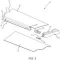
- FIG 3 an exploded view of the wing box 10 is shown (note that Figure 3 does not show the trailing edge spar 20) in which the wing box 10 includes an outboard end rib 25 located at the outboard end of the wing 3.
- the rib is a metal rib, although the skilled person will realise that the rib could be made of other materials known in the art, such as a composite material.
- the outboard rib 25 includes an attachment portion (not shown) that attaches to a wing tip device (not shown).
- the assembly includes a recess 30 at a longitudinal end of the fold region 17 of the integrated spar-cover 11 that separates a portion of the cover 12 and the spar 14.
- the recess 30 extends in the direction of the curved fold axis between the cover 12 and spar 14.
- a reinforcement element 35 extends between the cover 12 and the spar 14 across the recess 30 to reinforce the recess.
- the reinforcement element 35 is attached to the end rib 25.
- the assembly also includes an attachment bracket 28 that spans across the spar-flange 16 and lower attachment portion 27 of the end-rib 25, as will be explained in further detail with reference to Figure 6 .
- the wing box 10 assembly involves attaching the spar-cover 11 to the end rib 25 by attaching the upper cover 12 of the spar-cover 11 to a corresponding upper attachment portion 26 of the end rib 25, and attaching the flange 16 of the leading edge spar 14 to a corresponding lower attachment portion 27 of the end rib 25.
- the design and assembly of the wings 3 is typically undertaken by using the inboard end of the wing 3 and the lower cover 18 of the wing box 10 as a datum.
- any variations in the tolerances of the wing box 10 dimensions are exacerbated at the outboard end of the wing 3 towards the connection of the wing box 10 with the end rib 25. Consequently, tolerance control in the sizes of the spar-cover 11, particularly the height of the spar-web 15, needs to be carefully maintained in order that the upper cover 12 aligns well with the upper attachment portion 26 of the end rib 25.
- the spar-cover 11 comprises composite material, such as carbon fibre reinforced polymer. It is desirable to make the spar-cover 11 continuous along its length, without any discontinuity in the structure, so that the load path of the stresses in the wings 3 is relatively uninterrupted.
- tolerance control of composite material parts can be particularly challenging due to the reliance on accurate tooling, and the increased costs of that tooling as the part size increases, as well as the need to manage and control shrinkage of the composite parts during and after the cure process.
- the out-of-plane curvature of the spar-cover 11, in this case Z-shaped makes the spar-cover 11 relatively inflexible and not tolerant to geometrical inaccuracies during assembly. As a result, it is particularly important to control and/or mitigate the tolerances of the spar-cover 11.
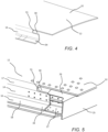
- a recess 30 is formed in the fold region 17 between the spar 14 and cover 12, to form a spar end region 34 and a cover end region 32 separated by the recess 30, as shown in more detail in Figure 4 .
- the recess 30 is located at a longitudinal end of the fold region 17 on the integrated spar-cover 11 adjacent to the attachment location of the end rib 25, as shown in Figure 5 .
- the recess 30 extends in the direction of the curved fold axis between the cover 12 and spar 14, i.e. substantially in the spanwise direction of the wing 3.
- a juncture 31 exists between the recess 30 and the longitudinal end of the fold region 17.
- the juncture 31 is arcuate such that the recess 30 has a curved interface with the fold region 17.
- the juncture may have other shapes, for example the juncture 31 may be stepped and/or tapered.
- the recess 30 provides additional flexibility to the end regions 32, 34 by decoupling the cover 12 and spar 14 along a portion of the length of the spar-cover 11, allowing the end regions 32, 34 some flexibility relative to each other and the remaining sections of the spar-cover 11, and therefore facilitates them to be deflected and thereby aligned with the attachment portions 26, 27 of the end rib 25.
- the recess 30 allows the spar 14 to deflect in the vertical and chordwise directions, thereby assisting in the alignment of the spar-cover 11 with the end rib 25.
- Decoupling of the cover 12 and spar 14 of the integral spar-cover 11 reduces or eliminates the need for time consuming and costly shimming operations at the interfaces between the spar-cover 11, end rib 25, and lower cover 18.
- the decoupling resulting from the recess 30 also reduces the requirement for expensive thickness control measures being built into the spar-cover manufacturing process.
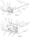
- the assembly of the wing box 10 to the end rib 25 is shown in Figures 5 to 7 .
- the wing box 10 is assembled by aligning the spar-flange 16 with the lower attachment portion 27 of the end rib 25, for example by taking a plane of the lower cover 18 as a datum from which to build up from.
- the cover end region 32 is then bent into a deflected position with respect to the spar end region 34 and inboard sections of the spar-cover 11 in order to align the cover end region 32 with an upper end of the end rib 25, such as the upper attachment portion 26.
- the spar end region 34 is attached to the end rib 25 using the attachment bracket 28 shown in Figure 6 , which spans between the spar end region 34 and a lower attachment portion 27 of the end rib 25.
- the attachment bracket 28 varies in thickness along its extent, such that the portion abutting the end rib 25 is thicker than the portion abutting the leading edge spar 14, so as to align the flange 16 of the leading edge spar 14 to the lower attachment portion 27 of the end rib 25.
- the dimensions of the attachment bracket 28 may be tailored to the particular requirements of the individual wing box 10 being assembled, i.e. matched machining, and may or may not vary in thickness.
- the flange 16 of the leading edge spar 14 may be attached directly to the lower attachment portion 27 of the end rib 25, without the use of an attachment bracket.
- the cover 12 may be attached indirectly to the end rib 25 using an attachment bracket 28.
- the spar-web 15 may attach to a corresponding attachment portion of the end rib 25 in addition or instead of the aforementioned attachment between the spar-cover 11 and end rib 25.
- the cover end region 32 is attached to the upper attachment portion 26 of the end rib 25.
- Fasteners 40 can be used to couple the components together, some of which are shown in Figures 6 and 7 .
- Other fastening means such as adhesive, may be used in conjunction or as an alternative.
- the decoupling of the cover 12 and spar 14 assists in aligning the horizontally inclined spar-flange 16 and upper cover 12, in order that they can be attached to the end rib 25, by making use of the vertical compliance of the spar end region 34 and cover end region 32 relative to the spar-cover 11 region inboard of the juncture.
- the spar-web 15 may also be attached to the end rib 25, and in this case the assembly process makes use of the fore-aft compliance available to the spar end region 34 relative to the spar-cover 11 region inboard of the juncture.
- the recess 30 creates a discontinuity in the composite spar-cover 11.
- Figures 8 and 9 show that the recess 30 is reinforced with a reinforcement element 35 that extends between the cover end region 32 and the spar end region 34 to couple the spar end region 34 with the cover end region 32.
- the reinforcement element 35 bridges between the cover end region 32 and spar end region 34, and may be referred to as a bridging member.
- the reinforcement element 35 is located on the inner side of the fold region 17, although in other examples it may be on the outside of the fold region 17.
- the reinforcement element 35 overlaps the juncture 31 between the longitudinal end of the fold region 17 and the recess 30.
- the reinforcement element 35 extends from a location inboard of the juncture 31 and extends outboard to abut the end rib 25.
- the reinforcement element 35 helps to restore the shear continuity between the spar-web 15 and cover 12 of the spar-cover 11.
- the reinforcement element 35 attaches to the end rib 25 with a plurality of fasteners to form a vertical shear joint between the spar-web 15 and end rib 25 and a horizontal shear joint between the upper cover 12 and the end rib 25.
- the reinforcement element 35 reinforces the juncture region 31 in order to control the composite strains in the recess 30, maintain the juncture dimensions (e.g. radius) and prevent unfolding at the recess 30 (particularly at the juncture 31).
- the recess 30 is a discrete recess 30, such that the cover 12 and spar 14 are integral components.
- the recess 30 may extend up to 0.5%, 1%, 2%, 5%, 10% or 20% of the total length of the spar-cover 11.
- the recess 30 is a cutaway.
- the recess 30 is a discontinuity between the cover 12 and spar 14.
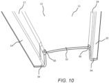
- Figure 10 shows a further example in which the integrated spar-cover is substantially Omega-shaped (alternatively referred to as U-shaped) due to the trailing edge spar 20 being integrally formed with the cover panel 12 through a second fold region 19 created between the trailing edge spar 20 and the upper cover 12 such that the material of the leading edge spar 14 extends continuously into the upper cover 12 through the first fold region 17 and continues to extend into the trailing edge spar 20 through the second fold region 19.
- the first and second fold regions 17, 19 extend substantially in the longitudinal spanwise direction of the wing 3.
- the integrated spars 14, 20 are decoupled from the upper cover panel 12 by first and second recesses 30, to form spar end regions 34 and a cover end region 32 separated by the recess 30.
- the recesses 30 are located at a longitudinal end of the fold regions 17, 19 on the integrated spar-cover 11 adjacent to the position the end rib 25 is attached.
- the recesses 30 provide additional flexibility to the end regions 32, 34 by decoupling the cover 12 from the leading edge spar 14 and trailing edge spar 20 along a portion of the length of the spar-cover 11, allowing the end regions 32, 34 some flexibility relative to each other and the remaining sections of the spar-cover 11.
- the relative flexibility of the end regions 32, 34 of the spar-cover 11 may have advantages in terms of reparability.
- a new component introduced to replace a damaged component, such as an end rib may be sized differently due to tolerancing or other factors.
- the decoupling of the spar and cover allows any tolerance variation of the new end rib compared to the replaced end rib to be accommodated for.
- the reinforcement element 35 is shown to be attached to the end rib 25.
- the reinforcement may extend between the cover end region 32 and the spar end region 34 to couple the spar end region 34 with the cover end region 32 but not be attached directly to the end rib 25.
- the integrated Z-shaped spar-cover 11 may include a lower cover and a trailing edge spar, or a lower cover and a leading edge spar, or an upper cover and a trailing edge spar.
- the omega-shaped spar-cover may include a lower cover integrated with a leading edge spar and a trailing edge spar, or one of the leading and trailing edge spars integrated with the upper and lower covers.
- the spar-cover 11 is shown connecting to an end-rib 25.
- the rib may be a mid-rib located at a mid-span location on the wing 3 inboard of the end-rib 25.
Landscapes
- Engineering & Computer Science (AREA)
- Aviation & Aerospace Engineering (AREA)
- Mechanical Engineering (AREA)
- Manufacturing & Machinery (AREA)
- Transportation (AREA)
- Structures Of Non-Positive Displacement Pumps (AREA)
- Connection Of Plates (AREA)
Claims (15)
- Flugzeuganordnung, umfassendeinen Längsholm (14) undeine Flügelabdeckung (12),wobei der Holm (14) und die Abdeckung (12) integral aus einem Verbundlaminatmaterial gebildet sind, um eine Holmabdeckung (11) derart zu bilden, dass sich das Verbundmaterial des Holms (14) kontinuierlich in die Abdeckung (12) durch einen Faltbereich (17) erstreckt, der zwischen dem Holm (14) und der Abdeckung (12) erzeugt wird,wobei der Holm (14) einen Holmendbereich (34) aufweist und die Abdeckung (12) einen Abdeckungsendbereich (32) aufweist,dadurch gekennzeichnet, dass der Holmendbereich (34) und der Abdeckungsendbereich (32) durch eine Vertiefung (30) an einem Längsende des Faltbereichs (17) getrennt sind undwobei sich ein Verstärkungselement (35) zwischen dem Holmendbereich (34) und dem Abdeckungsendbereich (32) erstreckt, so dass der Holmendbereich (34) mit dem Abdeckungsendbereich (32) verbunden wird.
- Flugzeuganordnung nach Anspruch 1, wobei die Flügelabdeckung (12) eine obere Flügelabdeckung ist und die Flugzeuganordnung eine untere Flügelabdeckung (18) und ein Strukturelement (25) umfasst, wobei sich das Strukturelement (25) zwischen dem Abdeckungsendbereich (32) der oberen Abdeckung und der unteren Abdeckung (18) erstreckt.
- Flugzeuganordnung nach Anspruch 2, wobei der Abdeckungsendbereich (32) in einer ausgelenkten Position gehalten wird, um das Strukturelement (25) zwischen dem Abdeckungsendbereich der oberen Abdeckung und der unteren Abdeckung zu fixieren.
- Flugzeuganordnung nach Anspruch 2 oder 3, wobei das Strukturelement (25) ein Spant an einem Außenende der Flugzeuganordnung ist.
- Flugzeuganordnung nach einem der vorherigen Ansprüche, wobei die Flugzeuganordnung eine Flügelanordnung ist und das Strukturelement (25) angeordnet ist, um ein Winglet zu montieren.
- Flugzeuganordnung nach einem der Ansprüche 2 bis 5, wobei die Holmabdeckung (11) einen ersten Schenkel entsprechend der oberen Abdeckung (12), einen zweiten Schenkel entsprechend einem Holmsteg (15) und einen dritten Schenkel entsprechend einem Holmflansch (16) zur Anbringung an der unteren Abdeckung (18) aufweist.
- Flugzeuganordnung nach einem der Ansprüche 2 bis 6, wobei das Verstärkungselement (35) an dem Strukturelement (25) anliegt.
- Flugzeuganordnung nach einem der vorherigen Ansprüche, wobei der Faltbereich (17) eine gekrümmte Faltachse aufweist, die sich im Wesentlichen in der Längsrichtung des Holms (14) erstreckt, und sich die Vertiefung (30) in der Richtung der gekrümmten Faltachse erstreckt.
- Flugzeuganordnung nach einem der vorherigen Ansprüche, wobei das Verstärkungselement (35) den Holmendbereich (34) und/oder den Deckelendbereich (32) in einer ausgelenkten Position hält.
- Flugzeuganordnung nach einem der vorherigen Ansprüche, wobei das Verstärkungselement (35) eine Verbindungsstelle (31) zwischen dem Längsende des Faltbereichs (17) und der Vertiefung (30) überlappt, wobei die Verbindungsstelle (31) optional bogenförmig ist.
- Flugzeuganordnung nach einem der vorherigen Ansprüche, wobei das Verstärkungselement (35) ein Metall umfasst.
- Flugzeuganordnung nach einem der vorherigen Ansprüche, wobei der Holm (14) ein erster Holm ist und die Anordnung einen zweiten Holm (20) umfasst, wobei der zweite Holm (20) und die Abdeckung (12) integral aus einem Verbundlaminatmaterial derart gebildet sind, dass sich das Verbundmaterial des zweiten Holms (20) kontinuierlich in die Abdeckung (12) durch einen zweiten Faltbereich (19) erstreckt, der zwischen dem zweiten Holm (20) und der Abdeckung (12) erzeugt wird, wobei ein zweiter Holmendbereich (34) des zweiten Holms (20) und ein Abdeckungsendbereich (32) der Abdeckung (12) durch eine zweite Vertiefung (30) an einem Längsende des zweiten Faltbereichs (19) getrennt sind und wobei sich ein zweites Verstärkungselement (25) zwischen dem zweiten Holmendbereich (34) und dem Abdeckungsendbereich (32) erstreckt, so dass der zweite Holmendbereich (34) mit dem Abdeckungsendbereich (32) verbunden wird.
- Flugzeug (1), umfassend die Flugzeuganordnung nach einem der vorherigen Ansprüche.
- Verfahren zum Zusammenbau einer Flugzeuganordnung, die Flugzeuganordnung umfassend:ein Strukturelement (25), einen Längsholm (14) und eine Flügelabdeckung (12),wobei der Holm (14) und die Abdeckung (12) integral aus einem Verbundlaminatmaterial gebildet sind, um eine Holmabdeckung (11) derart zu bilden, dass sich das Verbundmaterial des Holms (14) kontinuierlich in die Abdeckung (12) durch einen Faltbereich (17) erstreckt, der zwischen dem Holm und der Abdeckung erzeugt wird, wobei der Holm (14) einen Holmendbereich (34) aufweist und die Abdeckung (12) einen Abdeckungsendbereich (32) aufweist,wobei das Verfahren gekennzeichnet ist durch:Ausbilden einer Vertiefung (30) in dem Faltbereich (17), um den Holm (14) und die Abdeckung (12) an einem Längsende der integral ausgebildeten Holmabdeckung (11) zu trennen,Anbringen des Holmendbereichs (34) an dem Strukturelement,Anbringen des Abdeckungsendbereichs (32) an dem Strukturelement,Verbinden des Abdeckungsendbereichs (32) mit dem Holmendbereich (34) mit einem Verstärkungselement (35).
- Verfahren nach Anspruch 14, umfassend die Schritte: Ausrichten des HolmEndbereichs mit einem unteren Ende des Strukturelements, Biegen des Abdeckungs-Endbereichs, so dass es mit einem oberen Ende des Strukturelements ausgerichtet ist.
Applications Claiming Priority (2)
| Application Number | Priority Date | Filing Date | Title |
|---|---|---|---|
| GB1907797.3A GB2584634A (en) | 2019-05-31 | 2019-05-31 | Aircraft assembly having an integral spar-cover |
| PCT/EP2020/064796 WO2020239888A1 (en) | 2019-05-31 | 2020-05-28 | Aircraft assembly having an integral spar-cover |
Publications (2)
| Publication Number | Publication Date |
|---|---|
| EP3898409A1 EP3898409A1 (de) | 2021-10-27 |
| EP3898409B1 true EP3898409B1 (de) | 2023-05-17 |
Family
ID=67385743
Family Applications (1)
| Application Number | Title | Priority Date | Filing Date |
|---|---|---|---|
| EP20732124.1A Active EP3898409B1 (de) | 2019-05-31 | 2020-05-28 | Flugzeuganordnung mit integrierter holmabdeckung |
Country Status (5)
| Country | Link |
|---|---|
| US (1) | US12077289B2 (de) |
| EP (1) | EP3898409B1 (de) |
| CN (1) | CN113365912A (de) |
| GB (1) | GB2584634A (de) |
| WO (1) | WO2020239888A1 (de) |
Family Cites Families (14)
| Publication number | Priority date | Publication date | Assignee | Title |
|---|---|---|---|---|
| US2496024A (en) | 1946-03-12 | 1950-01-31 | Grumman Aircraft Engineering C | Airplane wing structure |
| DE2109692C3 (de) * | 1971-03-02 | 1981-06-04 | Vereinigte Flugtechnische Werke Gmbh, 2800 Bremen | Flügelkasten für Luftfahrzeuge in Verbundbauweise |
| US4437426A (en) | 1981-12-21 | 1984-03-20 | Fiberglass Unlimited, Inc. | Wing type air foil assembly |
| GB0906952D0 (en) * | 2009-04-23 | 2009-06-03 | Airbus Uk Ltd | Aircraft assembly and spar |
| GB201103122D0 (en) * | 2011-02-23 | 2011-04-06 | Airbus Uk Ltd | Composite structure |
| GB201307066D0 (en) * | 2013-04-18 | 2013-05-29 | Airbus Operations Ltd | Winglet and braided composite spar |
| GB2533582A (en) * | 2014-12-22 | 2016-06-29 | Airbus Operations Ltd | Aircraft wing box, aircraft wing, aircraft and supporting member for use therein |
| EP3095691A1 (de) * | 2015-05-22 | 2016-11-23 | Airbus Operations, S.L. | Mehrholmtorsionskastenstruktur |
| EP3170742B1 (de) * | 2015-11-18 | 2018-02-21 | Airbus Operations GmbH | Klappbare flügel für ein flugzeug und flugzeug mit einem klappbaren flügel |
| GB2550403A (en) * | 2016-05-19 | 2017-11-22 | Airbus Operations Ltd | Aerofoil body with integral curved spar-cover |
| GB2552216A (en) * | 2016-07-14 | 2018-01-17 | Airbus Operations Ltd | Stiffened aerospace structure and method of manufacture |
| US10179640B2 (en) * | 2016-08-24 | 2019-01-15 | The Boeing Company | Wing and method of manufacturing |
| GB2557274A (en) * | 2016-12-02 | 2018-06-20 | Airbus Operations Ltd | Aerofoil structure components |
| GB201709891D0 (en) * | 2017-06-21 | 2017-08-02 | Elson Space Eng Ese Ltd | Aerial vehicle |
-
2019
- 2019-05-31 GB GB1907797.3A patent/GB2584634A/en not_active Withdrawn
-
2020
- 2020-05-28 EP EP20732124.1A patent/EP3898409B1/de active Active
- 2020-05-28 CN CN202080011646.3A patent/CN113365912A/zh active Pending
- 2020-05-28 US US17/426,494 patent/US12077289B2/en active Active
- 2020-05-28 WO PCT/EP2020/064796 patent/WO2020239888A1/en unknown
Also Published As
| Publication number | Publication date |
|---|---|
| EP3898409A1 (de) | 2021-10-27 |
| US20220097820A1 (en) | 2022-03-31 |
| GB201907797D0 (en) | 2019-07-17 |
| GB2584634A (en) | 2020-12-16 |
| WO2020239888A1 (en) | 2020-12-03 |
| CN113365912A (zh) | 2021-09-07 |
| US12077289B2 (en) | 2024-09-03 |
Similar Documents
| Publication | Publication Date | Title |
|---|---|---|
| KR102126090B1 (ko) | 부하 운반용 박스 구조체 및 그 제조 방법 | |
| US7887009B2 (en) | Methods and systems for attaching aircraft wings to fuselages | |
| US9580164B2 (en) | Apparatus and methods for joining aircraft composite structures | |
| EP3395671B1 (de) | Tragflächenkörper mit integrierter holmabdeckung | |
| EP1999013B1 (de) | Flugzeugkomponente | |
| EP3243744B1 (de) | Flugzeugverbindung | |
| EP3599157B1 (de) | Flügelanordnung mit flüssigkeitsleitung | |
| EP2786932A2 (de) | Kontinuierlich gekrümmter Holm und Verfahren zur Herstellung | |
| US12091155B2 (en) | Structural arrangement for strut-braced wing assembly of an aircraft | |
| EP3546343A1 (de) | Flügelklappe mit drehmomentelement und verfahren zur formung davon | |
| EP3891064B1 (de) | Rippenbefestigungsanordnung | |
| EP2626291B1 (de) | Strukturelle Verbindung mit durchgehendem Hautfeld und Innen- und Außenanschlussstringern | |
| EP3424813B1 (de) | Paneel-aussenhautschnittstelle eines luftfahrzeugs | |
| US10364017B2 (en) | Structural component | |
| EP2540618B1 (de) | Ausgleichplatte für die Verbindung zwischen Schottwand und Haut von Integraltanks | |
| EP3898409B1 (de) | Flugzeuganordnung mit integrierter holmabdeckung | |
| US7677496B2 (en) | Stringer for an aircraft wing and a method of reinforcing thereof | |
| US20230373610A1 (en) | A cover panel | |
| US20240174344A1 (en) | Flow body for an aircraft with split ribs |
Legal Events
| Date | Code | Title | Description |
|---|---|---|---|
| STAA | Information on the status of an ep patent application or granted ep patent |
Free format text: STATUS: UNKNOWN |
|
| STAA | Information on the status of an ep patent application or granted ep patent |
Free format text: STATUS: THE INTERNATIONAL PUBLICATION HAS BEEN MADE |
|
| PUAI | Public reference made under article 153(3) epc to a published international application that has entered the european phase |
Free format text: ORIGINAL CODE: 0009012 |
|
| STAA | Information on the status of an ep patent application or granted ep patent |
Free format text: STATUS: REQUEST FOR EXAMINATION WAS MADE |
|
| 17P | Request for examination filed |
Effective date: 20210722 |
|
| AK | Designated contracting states |
Kind code of ref document: A1 Designated state(s): AL AT BE BG CH CY CZ DE DK EE ES FI FR GB GR HR HU IE IS IT LI LT LU LV MC MK MT NL NO PL PT RO RS SE SI SK SM TR |
|
| DAV | Request for validation of the european patent (deleted) | ||
| DAX | Request for extension of the european patent (deleted) | ||
| GRAP | Despatch of communication of intention to grant a patent |
Free format text: ORIGINAL CODE: EPIDOSNIGR1 |
|
| STAA | Information on the status of an ep patent application or granted ep patent |
Free format text: STATUS: GRANT OF PATENT IS INTENDED |
|
| INTG | Intention to grant announced |
Effective date: 20230131 |
|
| GRAS | Grant fee paid |
Free format text: ORIGINAL CODE: EPIDOSNIGR3 |
|
| GRAA | (expected) grant |
Free format text: ORIGINAL CODE: 0009210 |
|
| STAA | Information on the status of an ep patent application or granted ep patent |
Free format text: STATUS: THE PATENT HAS BEEN GRANTED |
|
| AK | Designated contracting states |
Kind code of ref document: B1 Designated state(s): AL AT BE BG CH CY CZ DE DK EE ES FI FR GB GR HR HU IE IS IT LI LT LU LV MC MK MT NL NO PL PT RO RS SE SI SK SM TR |
|
| REG | Reference to a national code |
Ref country code: GB Ref legal event code: FG4D |
|
| REG | Reference to a national code |
Ref country code: DE Ref legal event code: R096 Ref document number: 602020010962 Country of ref document: DE |
|
| REG | Reference to a national code |
Ref country code: CH Ref legal event code: EP |
|
| REG | Reference to a national code |
Ref country code: IE Ref legal event code: FG4D |
|
| REG | Reference to a national code |
Ref country code: AT Ref legal event code: REF Ref document number: 1568293 Country of ref document: AT Kind code of ref document: T Effective date: 20230615 |
|
| REG | Reference to a national code |
Ref country code: LT Ref legal event code: MG9D |
|
| REG | Reference to a national code |
Ref country code: NL Ref legal event code: MP Effective date: 20230517 |
|
| REG | Reference to a national code |
Ref country code: AT Ref legal event code: MK05 Ref document number: 1568293 Country of ref document: AT Kind code of ref document: T Effective date: 20230517 |
|
| PG25 | Lapsed in a contracting state [announced via postgrant information from national office to epo] |
Ref country code: SE Free format text: LAPSE BECAUSE OF FAILURE TO SUBMIT A TRANSLATION OF THE DESCRIPTION OR TO PAY THE FEE WITHIN THE PRESCRIBED TIME-LIMIT Effective date: 20230517 Ref country code: PT Free format text: LAPSE BECAUSE OF FAILURE TO SUBMIT A TRANSLATION OF THE DESCRIPTION OR TO PAY THE FEE WITHIN THE PRESCRIBED TIME-LIMIT Effective date: 20230918 Ref country code: NO Free format text: LAPSE BECAUSE OF FAILURE TO SUBMIT A TRANSLATION OF THE DESCRIPTION OR TO PAY THE FEE WITHIN THE PRESCRIBED TIME-LIMIT Effective date: 20230817 Ref country code: NL Free format text: LAPSE BECAUSE OF FAILURE TO SUBMIT A TRANSLATION OF THE DESCRIPTION OR TO PAY THE FEE WITHIN THE PRESCRIBED TIME-LIMIT Effective date: 20230517 Ref country code: ES Free format text: LAPSE BECAUSE OF FAILURE TO SUBMIT A TRANSLATION OF THE DESCRIPTION OR TO PAY THE FEE WITHIN THE PRESCRIBED TIME-LIMIT Effective date: 20230517 Ref country code: AT Free format text: LAPSE BECAUSE OF FAILURE TO SUBMIT A TRANSLATION OF THE DESCRIPTION OR TO PAY THE FEE WITHIN THE PRESCRIBED TIME-LIMIT Effective date: 20230517 |
|
| PG25 | Lapsed in a contracting state [announced via postgrant information from national office to epo] |
Ref country code: RS Free format text: LAPSE BECAUSE OF FAILURE TO SUBMIT A TRANSLATION OF THE DESCRIPTION OR TO PAY THE FEE WITHIN THE PRESCRIBED TIME-LIMIT Effective date: 20230517 Ref country code: PL Free format text: LAPSE BECAUSE OF FAILURE TO SUBMIT A TRANSLATION OF THE DESCRIPTION OR TO PAY THE FEE WITHIN THE PRESCRIBED TIME-LIMIT Effective date: 20230517 Ref country code: LV Free format text: LAPSE BECAUSE OF FAILURE TO SUBMIT A TRANSLATION OF THE DESCRIPTION OR TO PAY THE FEE WITHIN THE PRESCRIBED TIME-LIMIT Effective date: 20230517 Ref country code: LT Free format text: LAPSE BECAUSE OF FAILURE TO SUBMIT A TRANSLATION OF THE DESCRIPTION OR TO PAY THE FEE WITHIN THE PRESCRIBED TIME-LIMIT Effective date: 20230517 Ref country code: IS Free format text: LAPSE BECAUSE OF FAILURE TO SUBMIT A TRANSLATION OF THE DESCRIPTION OR TO PAY THE FEE WITHIN THE PRESCRIBED TIME-LIMIT Effective date: 20230917 Ref country code: HR Free format text: LAPSE BECAUSE OF FAILURE TO SUBMIT A TRANSLATION OF THE DESCRIPTION OR TO PAY THE FEE WITHIN THE PRESCRIBED TIME-LIMIT Effective date: 20230517 Ref country code: GR Free format text: LAPSE BECAUSE OF FAILURE TO SUBMIT A TRANSLATION OF THE DESCRIPTION OR TO PAY THE FEE WITHIN THE PRESCRIBED TIME-LIMIT Effective date: 20230818 |
|
| PG25 | Lapsed in a contracting state [announced via postgrant information from national office to epo] |
Ref country code: FI Free format text: LAPSE BECAUSE OF FAILURE TO SUBMIT A TRANSLATION OF THE DESCRIPTION OR TO PAY THE FEE WITHIN THE PRESCRIBED TIME-LIMIT Effective date: 20230517 |
|
| REG | Reference to a national code |
Ref country code: CH Ref legal event code: PL |
|
| PG25 | Lapsed in a contracting state [announced via postgrant information from national office to epo] |
Ref country code: SK Free format text: LAPSE BECAUSE OF FAILURE TO SUBMIT A TRANSLATION OF THE DESCRIPTION OR TO PAY THE FEE WITHIN THE PRESCRIBED TIME-LIMIT Effective date: 20230517 |
|
| REG | Reference to a national code |
Ref country code: BE Ref legal event code: MM Effective date: 20230531 |
|
| PG25 | Lapsed in a contracting state [announced via postgrant information from national office to epo] |
Ref country code: SM Free format text: LAPSE BECAUSE OF FAILURE TO SUBMIT A TRANSLATION OF THE DESCRIPTION OR TO PAY THE FEE WITHIN THE PRESCRIBED TIME-LIMIT Effective date: 20230517 Ref country code: SK Free format text: LAPSE BECAUSE OF FAILURE TO SUBMIT A TRANSLATION OF THE DESCRIPTION OR TO PAY THE FEE WITHIN THE PRESCRIBED TIME-LIMIT Effective date: 20230517 Ref country code: RO Free format text: LAPSE BECAUSE OF FAILURE TO SUBMIT A TRANSLATION OF THE DESCRIPTION OR TO PAY THE FEE WITHIN THE PRESCRIBED TIME-LIMIT Effective date: 20230517 Ref country code: LU Free format text: LAPSE BECAUSE OF NON-PAYMENT OF DUE FEES Effective date: 20230528 Ref country code: LI Free format text: LAPSE BECAUSE OF NON-PAYMENT OF DUE FEES Effective date: 20230531 Ref country code: EE Free format text: LAPSE BECAUSE OF FAILURE TO SUBMIT A TRANSLATION OF THE DESCRIPTION OR TO PAY THE FEE WITHIN THE PRESCRIBED TIME-LIMIT Effective date: 20230517 Ref country code: DK Free format text: LAPSE BECAUSE OF FAILURE TO SUBMIT A TRANSLATION OF THE DESCRIPTION OR TO PAY THE FEE WITHIN THE PRESCRIBED TIME-LIMIT Effective date: 20230517 Ref country code: CZ Free format text: LAPSE BECAUSE OF FAILURE TO SUBMIT A TRANSLATION OF THE DESCRIPTION OR TO PAY THE FEE WITHIN THE PRESCRIBED TIME-LIMIT Effective date: 20230517 Ref country code: CH Free format text: LAPSE BECAUSE OF NON-PAYMENT OF DUE FEES Effective date: 20230531 |
|
| REG | Reference to a national code |
Ref country code: DE Ref legal event code: R097 Ref document number: 602020010962 Country of ref document: DE |
|
| PG25 | Lapsed in a contracting state [announced via postgrant information from national office to epo] |
Ref country code: MC Free format text: LAPSE BECAUSE OF FAILURE TO SUBMIT A TRANSLATION OF THE DESCRIPTION OR TO PAY THE FEE WITHIN THE PRESCRIBED TIME-LIMIT Effective date: 20230517 |
|
| REG | Reference to a national code |
Ref country code: IE Ref legal event code: MM4A |
|
| PG25 | Lapsed in a contracting state [announced via postgrant information from national office to epo] |
Ref country code: MC Free format text: LAPSE BECAUSE OF FAILURE TO SUBMIT A TRANSLATION OF THE DESCRIPTION OR TO PAY THE FEE WITHIN THE PRESCRIBED TIME-LIMIT Effective date: 20230517 |
|
| PLBE | No opposition filed within time limit |
Free format text: ORIGINAL CODE: 0009261 |
|
| STAA | Information on the status of an ep patent application or granted ep patent |
Free format text: STATUS: NO OPPOSITION FILED WITHIN TIME LIMIT |
|
| PG25 | Lapsed in a contracting state [announced via postgrant information from national office to epo] |
Ref country code: IE Free format text: LAPSE BECAUSE OF NON-PAYMENT OF DUE FEES Effective date: 20230528 |
|
| 26N | No opposition filed |
Effective date: 20240220 |
|
| PG25 | Lapsed in a contracting state [announced via postgrant information from national office to epo] |
Ref country code: IE Free format text: LAPSE BECAUSE OF NON-PAYMENT OF DUE FEES Effective date: 20230528 |
|
| PG25 | Lapsed in a contracting state [announced via postgrant information from national office to epo] |
Ref country code: SI Free format text: LAPSE BECAUSE OF FAILURE TO SUBMIT A TRANSLATION OF THE DESCRIPTION OR TO PAY THE FEE WITHIN THE PRESCRIBED TIME-LIMIT Effective date: 20230517 |
|
| PG25 | Lapsed in a contracting state [announced via postgrant information from national office to epo] |
Ref country code: SI Free format text: LAPSE BECAUSE OF FAILURE TO SUBMIT A TRANSLATION OF THE DESCRIPTION OR TO PAY THE FEE WITHIN THE PRESCRIBED TIME-LIMIT Effective date: 20230517 Ref country code: IT Free format text: LAPSE BECAUSE OF FAILURE TO SUBMIT A TRANSLATION OF THE DESCRIPTION OR TO PAY THE FEE WITHIN THE PRESCRIBED TIME-LIMIT Effective date: 20230517 Ref country code: BE Free format text: LAPSE BECAUSE OF NON-PAYMENT OF DUE FEES Effective date: 20230531 |
|
| PGFP | Annual fee paid to national office [announced via postgrant information from national office to epo] |
Ref country code: GB Payment date: 20240521 Year of fee payment: 5 |
|
| PGFP | Annual fee paid to national office [announced via postgrant information from national office to epo] |
Ref country code: DE Payment date: 20240521 Year of fee payment: 5 |
|
| PGFP | Annual fee paid to national office [announced via postgrant information from national office to epo] |
Ref country code: FR Payment date: 20240527 Year of fee payment: 5 |