EP3897901B1 - Device for distributing a flow - Google Patents
Device for distributing a flow Download PDFInfo
- Publication number
- EP3897901B1 EP3897901B1 EP19817695.0A EP19817695A EP3897901B1 EP 3897901 B1 EP3897901 B1 EP 3897901B1 EP 19817695 A EP19817695 A EP 19817695A EP 3897901 B1 EP3897901 B1 EP 3897901B1
- Authority
- EP
- European Patent Office
- Prior art keywords
- fluid connection
- flow distribution
- fluid
- distribution device
- membrane
- Prior art date
- Legal status (The legal status is an assumption and is not a legal conclusion. Google has not performed a legal analysis and makes no representation as to the accuracy of the status listed.)
- Active
Links
Images





Classifications
-
- F—MECHANICAL ENGINEERING; LIGHTING; HEATING; WEAPONS; BLASTING
- F16—ENGINEERING ELEMENTS AND UNITS; GENERAL MEASURES FOR PRODUCING AND MAINTAINING EFFECTIVE FUNCTIONING OF MACHINES OR INSTALLATIONS; THERMAL INSULATION IN GENERAL
- F16K—VALVES; TAPS; COCKS; ACTUATING-FLOATS; DEVICES FOR VENTING OR AERATING
- F16K11/00—Multiple-way valves, e.g. mixing valves; Pipe fittings incorporating such valves
- F16K11/10—Multiple-way valves, e.g. mixing valves; Pipe fittings incorporating such valves with two or more closure members not moving as a unit
- F16K11/20—Multiple-way valves, e.g. mixing valves; Pipe fittings incorporating such valves with two or more closure members not moving as a unit operated by separate actuating members
- F16K11/22—Multiple-way valves, e.g. mixing valves; Pipe fittings incorporating such valves with two or more closure members not moving as a unit operated by separate actuating members with an actuating member for each valve, e.g. interconnected to form multiple-way valves
-
- C—CHEMISTRY; METALLURGY
- C12—BIOCHEMISTRY; BEER; SPIRITS; WINE; VINEGAR; MICROBIOLOGY; ENZYMOLOGY; MUTATION OR GENETIC ENGINEERING
- C12M—APPARATUS FOR ENZYMOLOGY OR MICROBIOLOGY; APPARATUS FOR CULTURING MICROORGANISMS FOR PRODUCING BIOMASS, FOR GROWING CELLS OR FOR OBTAINING FERMENTATION OR METABOLIC PRODUCTS, i.e. BIOREACTORS OR FERMENTERS
- C12M23/00—Constructional details, e.g. recesses, hinges
- C12M23/40—Manifolds; Distribution pieces
-
- C—CHEMISTRY; METALLURGY
- C12—BIOCHEMISTRY; BEER; SPIRITS; WINE; VINEGAR; MICROBIOLOGY; ENZYMOLOGY; MUTATION OR GENETIC ENGINEERING
- C12M—APPARATUS FOR ENZYMOLOGY OR MICROBIOLOGY; APPARATUS FOR CULTURING MICROORGANISMS FOR PRODUCING BIOMASS, FOR GROWING CELLS OR FOR OBTAINING FERMENTATION OR METABOLIC PRODUCTS, i.e. BIOREACTORS OR FERMENTERS
- C12M23/00—Constructional details, e.g. recesses, hinges
- C12M23/26—Constructional details, e.g. recesses, hinges flexible
-
- C—CHEMISTRY; METALLURGY
- C12—BIOCHEMISTRY; BEER; SPIRITS; WINE; VINEGAR; MICROBIOLOGY; ENZYMOLOGY; MUTATION OR GENETIC ENGINEERING
- C12M—APPARATUS FOR ENZYMOLOGY OR MICROBIOLOGY; APPARATUS FOR CULTURING MICROORGANISMS FOR PRODUCING BIOMASS, FOR GROWING CELLS OR FOR OBTAINING FERMENTATION OR METABOLIC PRODUCTS, i.e. BIOREACTORS OR FERMENTERS
- C12M23/00—Constructional details, e.g. recesses, hinges
- C12M23/28—Constructional details, e.g. recesses, hinges disposable or single use
-
- C—CHEMISTRY; METALLURGY
- C12—BIOCHEMISTRY; BEER; SPIRITS; WINE; VINEGAR; MICROBIOLOGY; ENZYMOLOGY; MUTATION OR GENETIC ENGINEERING
- C12M—APPARATUS FOR ENZYMOLOGY OR MICROBIOLOGY; APPARATUS FOR CULTURING MICROORGANISMS FOR PRODUCING BIOMASS, FOR GROWING CELLS OR FOR OBTAINING FERMENTATION OR METABOLIC PRODUCTS, i.e. BIOREACTORS OR FERMENTERS
- C12M41/00—Means for regulation, monitoring, measurement or control, e.g. flow regulation
- C12M41/40—Means for regulation, monitoring, measurement or control, e.g. flow regulation of pressure
-
- F—MECHANICAL ENGINEERING; LIGHTING; HEATING; WEAPONS; BLASTING
- F16—ENGINEERING ELEMENTS AND UNITS; GENERAL MEASURES FOR PRODUCING AND MAINTAINING EFFECTIVE FUNCTIONING OF MACHINES OR INSTALLATIONS; THERMAL INSULATION IN GENERAL
- F16K—VALVES; TAPS; COCKS; ACTUATING-FLOATS; DEVICES FOR VENTING OR AERATING
- F16K11/00—Multiple-way valves, e.g. mixing valves; Pipe fittings incorporating such valves
- F16K11/02—Multiple-way valves, e.g. mixing valves; Pipe fittings incorporating such valves with all movable sealing faces moving as one unit
- F16K11/022—Multiple-way valves, e.g. mixing valves; Pipe fittings incorporating such valves with all movable sealing faces moving as one unit comprising a deformable member
-
- F—MECHANICAL ENGINEERING; LIGHTING; HEATING; WEAPONS; BLASTING
- F16—ENGINEERING ELEMENTS AND UNITS; GENERAL MEASURES FOR PRODUCING AND MAINTAINING EFFECTIVE FUNCTIONING OF MACHINES OR INSTALLATIONS; THERMAL INSULATION IN GENERAL
- F16K—VALVES; TAPS; COCKS; ACTUATING-FLOATS; DEVICES FOR VENTING OR AERATING
- F16K27/00—Construction of housing; Use of materials therefor
- F16K27/02—Construction of housing; Use of materials therefor of lift valves
- F16K27/0236—Diaphragm cut-off apparatus
-
- F—MECHANICAL ENGINEERING; LIGHTING; HEATING; WEAPONS; BLASTING
- F16—ENGINEERING ELEMENTS AND UNITS; GENERAL MEASURES FOR PRODUCING AND MAINTAINING EFFECTIVE FUNCTIONING OF MACHINES OR INSTALLATIONS; THERMAL INSULATION IN GENERAL
- F16K—VALVES; TAPS; COCKS; ACTUATING-FLOATS; DEVICES FOR VENTING OR AERATING
- F16K31/00—Actuating devices; Operating means; Releasing devices
- F16K31/12—Actuating devices; Operating means; Releasing devices actuated by fluid
- F16K31/126—Actuating devices; Operating means; Releasing devices actuated by fluid the fluid acting on a diaphragm, bellows, or the like
- F16K31/1266—Actuating devices; Operating means; Releasing devices actuated by fluid the fluid acting on a diaphragm, bellows, or the like one side of the diaphragm being acted upon by the circulating fluid
-
- F—MECHANICAL ENGINEERING; LIGHTING; HEATING; WEAPONS; BLASTING
- F16—ENGINEERING ELEMENTS AND UNITS; GENERAL MEASURES FOR PRODUCING AND MAINTAINING EFFECTIVE FUNCTIONING OF MACHINES OR INSTALLATIONS; THERMAL INSULATION IN GENERAL
- F16K—VALVES; TAPS; COCKS; ACTUATING-FLOATS; DEVICES FOR VENTING OR AERATING
- F16K7/00—Diaphragm valves or cut-off apparatus, e.g. with a member deformed, but not moved bodily, to close the passage ; Pinch valves
- F16K7/12—Diaphragm valves or cut-off apparatus, e.g. with a member deformed, but not moved bodily, to close the passage ; Pinch valves with flat, dished, or bowl-shaped diaphragm
- F16K7/126—Diaphragm valves or cut-off apparatus, e.g. with a member deformed, but not moved bodily, to close the passage ; Pinch valves with flat, dished, or bowl-shaped diaphragm the seat being formed on a rib perpendicular to the fluid line
-
- B—PERFORMING OPERATIONS; TRANSPORTING
- B01—PHYSICAL OR CHEMICAL PROCESSES OR APPARATUS IN GENERAL
- B01D—SEPARATION
- B01D15/00—Separating processes involving the treatment of liquids with solid sorbents; Apparatus therefor
- B01D15/08—Selective adsorption, e.g. chromatography
-
- G—PHYSICS
- G01—MEASURING; TESTING
- G01N—INVESTIGATING OR ANALYSING MATERIALS BY DETERMINING THEIR CHEMICAL OR PHYSICAL PROPERTIES
- G01N30/00—Investigating or analysing materials by separation into components using adsorption, absorption or similar phenomena or using ion-exchange, e.g. chromatography or field flow fractionation
- G01N30/02—Column chromatography
- G01N30/04—Preparation or injection of sample to be analysed
- G01N30/16—Injection
- G01N30/20—Injection using a sampling valve
- G01N2030/205—Diaphragm valves, e.g. deformed member closing the passage
Definitions
- the present invention relates to a flow distribution device, a bioprocess separation system and a single use flow path for bioprocess systems.
- Diaphragm valves may be used in such liquid handling systems.
- a schematic illustration of a liquid handling system using diaphragm valves according to prior art is shown in Figure 1 .
- Four fluid modules 300 each comprising a T-shaped fluid conduit 302, two diaphragm valves 304 and two connectors 306 are shown connected to each other and to an external fluid conduit 308 and a pump P.
- four different fluid sources can for example be connected to an inlet of a chromatography system and, thanks to the provision of two diaphragm valves for each fluid source inlet, backflow and mixing can be avoided.
- Figures 2a-2d show views of a fluid distribution device 10 and a fluid distribution manifold 12 according to one embodiment of the invention.
- Figures 3a-3d show different views of a fluid distribution device 110 and a fluid distribution manifold 112 according to another embodiment of the invention.
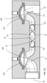
- Figures 2a and 3a show exploded perspective views of the fluid distribution device 10; 110, Figures 2b and 3b are cross section side views of the fluid distribution manifolds 12; 112 along the dotted lines of Figures 2c and 3c respectively.
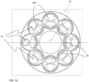
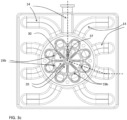
- Figures 2c and 3c are top views of the fluid distribution manifolds 12; 112 without membranes provided and
- Figures 2d and 3d are perspective view of the fluid distribution manifolds 12; 112 as mounted.
- the two different embodiments will be described together below and the same reference numbers will be used for corresponding parts in the two different embodiments.
- fluid connection conduits 14 can comprise a membrane 19a and a valve seat 19b or optionally also all fluid conduits except two comprise a membrane 19a and a valve seat 19b. It can also be expressed, as in the claims, that at least three of the fluid connection conduits 14 when there are at least four fluid connection conduits 14 comprise a membrane 19a and a valve seat 19b. Actuation of the membranes 19a into the at least two different positions is provided from membrane actuation members 41 provided in the fluid distribution device 10; 110 as will be further described below.
- the membranes 19a may comprise double-layered membranes. As shown in Figure 5 , a membrane 19a can then comprise the two membrane components 19a' and 19a". This mitigates the risk for inappropriate fluid flows in case one membrane component ruptures. Further, the components 19a' and 19a" may be spaced apart by a pattern of spacer elements 200, which can e.g. be studs, pillars, ribs etc. In the space 201 between the components a fluid sensor 202 (e.g. a conductivity sensor, pressure sensor etc.) can then be inserted to detect the presence of fluid due to the rupture of one of the components 19a' and 19a".
- a fluid sensor 202 e.g. a conductivity sensor, pressure sensor etc.
- central common compartment 30 has a form of a sphere or a spheroid which is the case in the embodiment as shown in Figures 2a-2d or is annular as is the case in the embodiment shown in Figures 3a-3d .
- the flow distribution device 10; 110 further comprises at least three membrane actuation members 41 which are provided in connection with one membrane 19a of the flow distribution manifold 12; 112 each.
- one membrane actuation member 41 is provided for each fluid connection conduit 14, i.e. eight membrane actuation members 41 are provided in the flow distribution device 12.
- all fluid connection conduits 14 except one are provided with a membrane actuation member 41.
- Each of said membrane actuation members 41 is configured for actuating the membrane 19a to be in at least two different positions in relation to the valve seat 19b, wherein a first position of the membrane 19a allows flow between the first end 18 and the second end 20 of the fluid connection conduit 14 and a second position of the membrane 19a prevents flow between the first end 18 and the second end 20 of the fluid connection conduit 14.
- the membrane actuation members 41 can be for example pressure controlling members such as tubes through which pressurized air or suction can be provided. Hereby the membranes can be controlled into the at least two different positions by controlling pressure in the membrane actuation members 41.
- Another alternative of membrane actuation members 41 can be some kind of rods in mechanical connection with the membranes whereby a displacement of the rod can be transferred to displacement of the membranes.
- the membranes 19a and valve seats 19b are suitably provided at a position of the fluid connection conduits 14 close to the second ends 20 of the fluid connection conduits 14.
- the distance d1 between the valve seat 19b and the second end 20 of the fluid connection conduit 14 can for example be less than four or less than three or less than two fluid connection tube 14 inner diameters ID.
- the distances between the second ends 20 of each of the fluid connection conduits 14 and a central point 37 of the central common compartment 30 will not differ by more than 3 or 2 or 1 times an inner diameter, ID, of the fluid connection conduits 14.
- the central common compartment 30 is symmetrical and the fluid connection conduits 14 are positioned symmetrical around the central common compartment 30 at substantially the same distance from a central point 37 of the central common compartment 30, i.e. a distance between the second end 20 of each of the fluid connection conduits 14 and a central point 37 of the central common compartment 20 is substantially the same for each fluid connection conduit 14.
- a difference from prior art flow delivery manifolds is that in prior art the fluid connections were provided in parallel while in this new invention at least some of the fluid connection conduits are provided in different directions, i.e. at least some of the fluid connection conduits 14 are spread out from the central common compartment 30.
- a distance from a center of the second end 20 of at least one of the fluid connection conduits 14 to a center of the second end 20 of an adjacent fluid connection conduit 14 is smaller than the distance between central points of two membranes 19a provided to the same two fluid connection conduits 14.
- the flow distribution manifold 12; 112 can be a single-use component. It can be molded from a suitable material, such as for example a polymer, and it can be provided with aseptic connectors for aseptic connection in a system.
- the flow distribution manifold 12; 112 can be pre-sterilized for example by gamma radiation or other sterilization methods, optionally together with other parts of a single-use flow path to be used for example in a bioprocess separation system, such as a chromatography system or a filter system as will be further described below.
- the flow distribution manifold 12; 112 can comprise three parts as disclosed in the exploded views is Figures 2a and 3a .
- a first part 20a comprises the fluid connection conduits 14, the valve seats 19b and the common compartment 30.
- one of the fluid connection conduits 14 has its first end 18 entering towards a side edge 22a of the first part 20a and all the other fluid connection conduits 14 have their first ends 18 entering towards a bottom side 22b of the first part 20a, see Figures 2d and 3d .
- This may be suitable when connecting the fluid distribution device 10; 110 in a system, for example to an inlet or an outlet of a bioprocess separation system as will be further described in relation to Figure 4 below.
- a second part 20b of the flow distribution manifold 12; 112 comprises the membranes 19a and a third part 20c of the flow distribution manifold 12; 112 comprises connections 24 for allowing connection to membrane actuation members 41 and mating them to one membrane 19a each.
- the present invention also relates to a bioprocess separation system 71 as schematically shown in Figure 4 , such as a chromatography system or a filter system, which comprises one or more fluid distribution devices 10; 110 as described above.
- One fluid distribution device 10; 110 can be connected to an inlet 75 of a separation device 73 provided in the bioprocess separation system 71 and/or one fluid distribution device 10; 110 can be connected to an outlet 77 of the separation device 73.
- the separation device 73 can for example be a chromatography column or a filter.
- At least one pump 79 is also provided in the bioprocess separation system 71.
- Other components such as valves and sensors are normally also provided in the bioprocess separation system 71 but will not be described in further detail here.
- a single-use flow path 81 comprising flow paths, the flow distribution manifold 12; 112 according to the invention and optionally also the separation device 73 is also part of the present invention, i.e. the flow distribution manifold 12; 112 can be connected to other flow paths of a bioprocess separation system and be pre-sterilized for easy connection and exchange in a bioprocess separation system 71.
- Reusable parts of the bioprocess separation system 71 are for example pump heads 79 and the membrane actuation members 41 of the flow distribution device 10; 110.
- the central common compartment 30 of the fluid distribution manifold 12; 112 according to the invention can optionally be provided with a sensor, for example an air sensor, pressure sensor or a conductivity sensor.
- a sensor for example an air sensor, pressure sensor or a conductivity sensor.
- the fluid distribution device 10; 110 is compact and flexible. It can be positioned remote from a system where it is used because of the valve control provided by pressurized air.
- the flow distribution manifold is suitable for single-use applications.
- the flow distribution manifold, and optionally a single use flow path to which it can be connected can be pre-sterilized by for example gamma radiation and can be provided with aseptic connectors for aseptic connection in a system.
- the single-use technology is important in the bioprocess industry in order to reduce production cost, increase production throughput and quality and to increase safety.
- wetted parts that are in contact with the process fluid and drug product during processing such as for example fluid storage vessels, tubing, separation equipment etc., are provided as clean and ready to use consumables which are to be installed and used for a specific process, product or over a limited time only and to be disposed thereafter.
- SUT consumables are typically produced, configured and packaged in clean room environments to avoid contamination with microorganisms, particulates etc.
- SUT wetted parts can further be provided clean and pre-sterilized, thus allowing for aseptic and/or sterile processing, hereby reducing above mentioned risks relevant for product, operator or patient safety.
- SUT wetted parts are subjected to a sterilizing gamma irradiation treatment prior to use in the biomanufacturing process, and when doing so they are deployed as 'pre-sterilized' at the point of use.
- SUT single-use technology
- the advantage of using single-use technology (SUT) fluid handling equipment is primarily that cross-contamination in between production batches and campaigns is eliminated when the SUT equipment is used for a single drug product only.
- the SUT equipment is disposed of after use, which can be after a single run, batch or campaign comprising multiple runs and batches.
- initial cleaning and sanitization for example by contacting the flow path with sodium hydroxide solutions
- sterilization can be avoided.
- This enables a LEAN manufacturing approach, because time consuming, costly and non-value adding steps can be omitted.
- cleaning post-use may be omitted.
- the elimination of cleaning procedures and required cleaning fluids further reduces clean water requirements to prepare cleaning solutions in the first place, fluid handling and waste treatment, which translates to reduced facility size and complexity.
- SUT systems provide higher flexibility in (re-)configuring a manufacturing facility and adapting it to different processes and products by design, i.e. through the reduced need for fixed installations compared to traditional processing systems and installations, which for example required auxiliary systems for CIP (Cleaning in Place) and SIP (Sterilization in place).
- CIP Cleaning in Place
- SIP Sterilization in place
- SUT equipment and SUT processing regimes are therefore available or are being made available for the majority of all types of equipment and/or unit operations, among them bioreactors for cell culture or fermentation, buffer bags for liquid storage, tubing and pumps for liquid transfer and filling operations, filters, chromatography columns and related systems for separations.
- SUT equipment does provide improved efficiency, safety and convenience compared to traditional installations and systems.
- Traditional installations and systems for processing are typically made from stainless steel and/or plastic and are not produced under controlled (or clean room) conditions reducing bioburden.
- Traditional systems are typically cleaned in place (CIP), sometimes also sterilized in place (SIP), which not only requires auxiliary installations, equipment and fluids, but involves also substantial time for validation, execution, and quality control of CIP and SIP procedures.
- CIP cleaned in place
- SIP sterilized in place
- the size, cost and complexity of facilities relying on traditional equipment and installations is significantly larger compared to production facilities deploying SUT.
- SUT facilities and processes can be planned, built and started up in significantly shorter time compared to traditional manufacturing technology, and SUT reduces capital investments and financial risk associated with a typically highly dynamic portfolio of drug products as well as risk and uncertainty related to the testing and approval of drug candidates and their product demand.
Landscapes
- Engineering & Computer Science (AREA)
- General Engineering & Computer Science (AREA)
- Health & Medical Sciences (AREA)
- Chemical & Material Sciences (AREA)
- Wood Science & Technology (AREA)
- Bioinformatics & Cheminformatics (AREA)
- Life Sciences & Earth Sciences (AREA)
- Zoology (AREA)
- Organic Chemistry (AREA)
- Mechanical Engineering (AREA)
- Biomedical Technology (AREA)
- Biotechnology (AREA)
- Microbiology (AREA)
- Sustainable Development (AREA)
- Biochemistry (AREA)
- General Health & Medical Sciences (AREA)
- Genetics & Genomics (AREA)
- Clinical Laboratory Science (AREA)
- Analytical Chemistry (AREA)
- Separation Using Semi-Permeable Membranes (AREA)
- Apparatus Associated With Microorganisms And Enzymes (AREA)
- Feeding, Discharge, Calcimining, Fusing, And Gas-Generation Devices (AREA)
- Multiple-Way Valves (AREA)
Description
- The present invention relates to a flow distribution device, a bioprocess separation system and a single use flow path for bioprocess systems.
- Valve operated fluid delivery devices are for example used in liquid handling systems applied in the bioprocess field, for example in chromatography systems or filter systems. See, for example,
US 4,879,029 A ,CN 108 757 995 A ,CN 106 499 841 A andWO 2013/147697 A1 . The valves can e.g. be diaphragm valves or pinch valves. For example, at an inlet to a chromatography column there may be a need to connect a number of different fluid sources, such as for example different samples, washing fluids and elution fluid. Likewise, at an outlet of a chromatography column there may be a need to connect to a number of different fraction collectors. Diaphragm valves may be used in such liquid handling systems. A schematic illustration of a liquid handling system using diaphragm valves according to prior art is shown inFigure 1 . Fourfluid modules 300 each comprising a T-shaped fluid conduit 302, twodiaphragm valves 304 and twoconnectors 306 are shown connected to each other and to anexternal fluid conduit 308 and a pump P. With such a liquid handling system, four different fluid sources can for example be connected to an inlet of a chromatography system and, thanks to the provision of two diaphragm valves for each fluid source inlet, backflow and mixing can be avoided. - A problem with such a liquid handling system is that it is complex and comprises many valves. It may also be difficult to clean.
- An object of the present invention is to provide an improved flow distribution device.
- A further object of the invention is to provide a flow distribution device with reduced risk for contamination and carry over.
- The present invention, as defined by the appended claims, is thus provided.
- Thereby a flow distribution device is provided with a reduced number of diaphragm valves compared to prior art devices. Furthermore, cleaning of the flow distribution device is facilitated and the risk for contamination and carry over is hereby decreased thanks to the design comprising a central common compartment into which the fluid connections are entering from different directions, i.e. there is a common compartment provided in the middle of the device. Hereby a "distance" between different connections can be the same.
-
-
Figure 1 shows schematically a device for delivery of fluid according to prior art. -
Figure 2a is an exploded perspective view of a flow distribution device comprising a flow distribution manifold according to one embodiment of the invention. -
Figure 2b is a cross section side view of the flow distribution manifold as shown inFigure 2a as mounted. -
Figure 2c is a top view of the flow distribution manifold as shown inFigures 2a and2b without a cover and without membranes. -
Figure 2d is a perspective view of the flow distribution manifold as shown inFigures 2a-2c as mounted. -
Figure 3a is an exploded perspective view of a flow distribution device comprising a flow distribution manifold according to another embodiment of the invention. -
Figure 3b is a cross section along the dotted lines inFigure 3c of the flow distribution manifold as shown inFigure 3a as mounted. -
Figure 3c is a top view of the flow distribution manifold as shown inFigures 3a and3b without a cover and without membranes. -
Figure 3d is a perspective view of the flow distribution manifold as shown inFigures 3a-3c as mounted. -
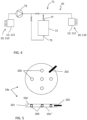
Figure 4 shows schematically a bioprocess separation system in which a flow distribution device according to the invention can be used. -
Figure 5 shows a double-layer membrane according to an embodiment of the invention. -
Figures 2a-2d show views of afluid distribution device 10 and afluid distribution manifold 12 according to one embodiment of the invention.Figures 3a-3d show different views of afluid distribution device 110 and afluid distribution manifold 112 according to another embodiment of the invention.Figures 2a and3a show exploded perspective views of thefluid distribution device 10; 110,Figures 2b and3b are cross section side views of the fluid distribution manifolds 12; 112 along the dotted lines ofFigures 2c and3c respectively.Figures 2c and3c are top views of thefluid distribution manifolds 12; 112 without membranes provided andFigures 2d and3d are perspective view of the fluid distribution manifolds 12; 112 as mounted. The two different embodiments will be described together below and the same reference numbers will be used for corresponding parts in the two different embodiments. - The
fluid distribution device 10; 110 comprises one part which can be a single-use part. This is called afluid distribution manifold 12; 112 and comprises at least fourfluid connection conduits 14. In another embodiment the fluid distribution manifold comprises at least five or at least sixfluid connection conduits 14. Eachfluid connection conduit 14 comprises afirst end 18 for fluid connection and an oppositesecond end 20. In the embodiment as shown inFigures 2a-2d eightfluid connection conduits 14 are shown and in the embodiment as shown inFigures 3a-3d ninefluid connection conduits 14 are shown, however the number of fluid connection conduits can of course be different. InFigure 2b two of the eightfluid connection conduits 14 of this embodiment are shown in cross section. Thefirst ends 18 and thesecond ends 20 of these twofluid connection conduits 14 can also be seen inFigure 2b . InFigure 3a , ninefluid connection conduits 14 can be seen. InFigures 2d and3d , all thefirst ends 18 of thefluid connection conduits 14 can be seen. In one embodiment of the invention at least all fluid connection conduits 14 except one comprise amembrane 19a and avalve seat 19b, whichmembrane 19a can be put in at least two different positions in relation to thevalve seat 19b for allowing or preventing fluid flow between thefirst end 18 and thesecond end 20 of this fluid connection conduit 14. In alternative language,membrane 19a is movable between an open position (at a distance fromvalve seat 19b) and a closed position (in sealing abutment withvalve seat 19b). In the open position, fluid flow betweenfirst end 18 andsecond end 20 is allowed and in the closed position it is prevented. Of course also allfluid connection conduits 14 can comprise amembrane 19a and avalve seat 19b or optionally also all fluid conduits except two comprise amembrane 19a and avalve seat 19b. It can also be expressed, as in the claims, that at least three of the fluid connection conduits 14 when there are at least fourfluid connection conduits 14 comprise amembrane 19a and avalve seat 19b. Actuation of themembranes 19a into the at least two different positions is provided frommembrane actuation members 41 provided in thefluid distribution device 10; 110 as will be further described below. - In certain embodiments, the
membranes 19a, such as eachmembrane 19a, may comprise double-layered membranes. As shown inFigure 5 , amembrane 19a can then comprise the twomembrane components 19a' and 19a". This mitigates the risk for inappropriate fluid flows in case one membrane component ruptures. Further, thecomponents 19a' and 19a" may be spaced apart by a pattern ofspacer elements 200, which can e.g. be studs, pillars, ribs etc. In thespace 201 between the components a fluid sensor 202 (e.g. a conductivity sensor, pressure sensor etc.) can then be inserted to detect the presence of fluid due to the rupture of one of thecomponents 19a' and 19a". - According to the invention the
fluid distribution manifold 12; 112 further comprises a centralcommon compartment 30 to which thesecond ends 20 of each of thefluid connection conduits 14 are connected, whereby thefirst ends 18 of each of thefluid connection conduits 14 can be in fluid communication with the centralcommon compartment 30, i.e. when thecorresponding membranes 19a are in the first (open) position. Furthermore, according to the invention thefluid connection conduits 14 are entering the centralcommon compartment 30 from at least three different directions. In another embodiment of the invention thefluid connection conduits 14 are entering the centralcommon compartment 30 from at least four or at least five different directions. In the embodiments shown inFigures 2a-2d and inFigures 3a-3d all thefluid connection conduits 14 are entering the centralcommon compartment 30 from different directions and thefluid distribution manifold 12 has a star-like configuration with the fluid connection conduits 14 pointing away from the centralcommon compartment 30 in different directions. In the embodiments shown inFigures 2 and3 thefluid connection conduits 14 are all provided in one and the same plane when entering into the centralcommon compartment 30 but they could as well be provided in different planes, i.e. thesecond ends 20 of thefluid connection conduits 14 can be connected to the centralcommon compartment 30 distributed around an enclosingwall 33 of the centralcommon compartment 30, which enclosingwall 33 is enclosing aninner room 35 of the centralcommon compartment 30, wherein each of thefluid connection conduits 14 can be in fluid communication with theinner room 35 of the centralcommon compartment 30, when thecorresponding membranes 19a are in the first (open) position), and wherein thefluid connection conduits 14 are entering the enclosingwall 33 of the centralcommon compartment 30 from at least two or three or four different directions. In the embodiments of the invention shown inFigures 2 and3 thefluid connection conduits 14 are entering the enclosingwall 33 of the centralcommon compartment 30 from eight and nine different directions respectively. As discussed above, fluid connection conduits could as well be provided entering the centralcommon compartment 30 from all directions, i.e. for example entering the central common compartment in a direction being substantially perpendicular in relation to the fluid connection conduits as shown inFigures 2 and3 . The centralcommon compartment 30 has a form of a sphere or a spheroid which is the case in the embodiment as shown inFigures 2a-2d or is annular as is the case in the embodiment shown inFigures 3a-3d . - The
flow distribution device 10; 110 further comprises at least threemembrane actuation members 41 which are provided in connection with onemembrane 19a of theflow distribution manifold 12; 112 each. In the embodiment of the invention as shown inFigures 2a-2d onemembrane actuation member 41 is provided for eachfluid connection conduit 14, i.e. eightmembrane actuation members 41 are provided in theflow distribution device 12. In the embodiment of the invention as shown inFigures 3a-3d allfluid connection conduits 14 except one are provided with amembrane actuation member 41. - Each of said
membrane actuation members 41 is configured for actuating themembrane 19a to be in at least two different positions in relation to thevalve seat 19b, wherein a first position of themembrane 19a allows flow between thefirst end 18 and thesecond end 20 of thefluid connection conduit 14 and a second position of themembrane 19a prevents flow between thefirst end 18 and thesecond end 20 of thefluid connection conduit 14. - The
membrane actuation members 41 can be for example pressure controlling members such as tubes through which pressurized air or suction can be provided. Hereby the membranes can be controlled into the at least two different positions by controlling pressure in themembrane actuation members 41. Another alternative ofmembrane actuation members 41 can be some kind of rods in mechanical connection with the membranes whereby a displacement of the rod can be transferred to displacement of the membranes. - The
membrane actuation members 41 can be configured for being controlled by a connected control system, whereby the positions of themembranes 19a in thefluid distribution manifold 12; 112 can be controlled form the control system such that thefirst end 18 of one of thefluid connection conduits 14 can be fluidly connected with thefirst end 18 of another one of thefluid connection conduits 14. In one embodiment of the invention thefirst end 18 of any one of the differentfluid connection conduits 14 can be connected with thefirst end 18 of any one of the otherfluid connection conduits 14. - The
membranes 19a andvalve seats 19b are suitably provided at a position of thefluid connection conduits 14 close to the second ends 20 of thefluid connection conduits 14. The distance d1 between thevalve seat 19b and thesecond end 20 of thefluid connection conduit 14 can for example be less than four or less than three or less than twofluid connection tube 14 inner diameters ID. - In some embodiments of the invention the distances between the second ends 20 of each of the
fluid connection conduits 14 and acentral point 37 of the centralcommon compartment 30 will not differ by more than 3 or 2 or 1 times an inner diameter, ID, of thefluid connection conduits 14. In the embodiments as shown inFigures 2a-2d and inFigures 3a-3d the centralcommon compartment 30 is symmetrical and thefluid connection conduits 14 are positioned symmetrical around the centralcommon compartment 30 at substantially the same distance from acentral point 37 of the centralcommon compartment 30, i.e. a distance between thesecond end 20 of each of thefluid connection conduits 14 and acentral point 37 of the centralcommon compartment 20 is substantially the same for eachfluid connection conduit 14. - A difference from prior art flow delivery manifolds is that in prior art the fluid connections were provided in parallel while in this new invention at least some of the fluid connection conduits are provided in different directions, i.e. at least some of the
fluid connection conduits 14 are spread out from the centralcommon compartment 30. Hereby a distance from a center of thesecond end 20 of at least one of thefluid connection conduits 14 to a center of thesecond end 20 of an adjacentfluid connection conduit 14 is smaller than the distance between central points of twomembranes 19a provided to the same twofluid connection conduits 14. - The
flow distribution manifold 12; 112 can be a single-use component. It can be molded from a suitable material, such as for example a polymer, and it can be provided with aseptic connectors for aseptic connection in a system. Theflow distribution manifold 12; 112 can be pre-sterilized for example by gamma radiation or other sterilization methods, optionally together with other parts of a single-use flow path to be used for example in a bioprocess separation system, such as a chromatography system or a filter system as will be further described below. - Another part of the
flow distribution device 10; 110 can be a reusable part and this part comprises themembrane actuation members 41. - The
flow distribution manifold 12; 112 can comprise three parts as disclosed in the exploded views isFigures 2a and3a . Afirst part 20a comprises thefluid connection conduits 14, the valve seats 19b and thecommon compartment 30. In both the embodiment shown inFigures 2a-2d and the embodiment shown inFigures 3a-3d one of thefluid connection conduits 14 has itsfirst end 18 entering towards aside edge 22a of thefirst part 20a and all the otherfluid connection conduits 14 have their first ends 18 entering towards abottom side 22b of thefirst part 20a, seeFigures 2d and3d . This may be suitable when connecting thefluid distribution device 10; 110 in a system, for example to an inlet or an outlet of a bioprocess separation system as will be further described in relation toFigure 4 below. Asecond part 20b of theflow distribution manifold 12; 112 comprises themembranes 19a and athird part 20c of theflow distribution manifold 12; 112 comprisesconnections 24 for allowing connection tomembrane actuation members 41 and mating them to onemembrane 19a each. - The present invention also relates to a
bioprocess separation system 71 as schematically shown inFigure 4 , such as a chromatography system or a filter system, which comprises one or morefluid distribution devices 10; 110 as described above. Onefluid distribution device 10; 110 can be connected to aninlet 75 of aseparation device 73 provided in thebioprocess separation system 71 and/or onefluid distribution device 10; 110 can be connected to anoutlet 77 of theseparation device 73. Theseparation device 73 can for example be a chromatography column or a filter. At least onepump 79 is also provided in thebioprocess separation system 71. Other components such as valves and sensors are normally also provided in thebioprocess separation system 71 but will not be described in further detail here. A single-use flow path 81 comprising flow paths, theflow distribution manifold 12; 112 according to the invention and optionally also theseparation device 73 is also part of the present invention, i.e. theflow distribution manifold 12; 112 can be connected to other flow paths of a bioprocess separation system and be pre-sterilized for easy connection and exchange in abioprocess separation system 71. Reusable parts of thebioprocess separation system 71 are for example pump heads 79 and themembrane actuation members 41 of theflow distribution device 10; 110. - The central
common compartment 30 of thefluid distribution manifold 12; 112 according to the invention can optionally be provided with a sensor, for example an air sensor, pressure sensor or a conductivity sensor. - The
fluid distribution device 10; 110 according to the invention is compact and flexible. It can be positioned remote from a system where it is used because of the valve control provided by pressurized air. - As discussed above the flow distribution manifold is suitable for single-use applications. The flow distribution manifold, and optionally a single use flow path to which it can be connected, can be pre-sterilized by for example gamma radiation and can be provided with aseptic connectors for aseptic connection in a system.
- The single-use technology (SUT) is important in the bioprocess industry in order to reduce production cost, increase production throughput and quality and to increase safety. With single-use processing technology and equipment, wetted parts that are in contact with the process fluid and drug product during processing, such as for example fluid storage vessels, tubing, separation equipment etc., are provided as clean and ready to use consumables which are to be installed and used for a specific process, product or over a limited time only and to be disposed thereafter.
- SUT consumables are typically produced, configured and packaged in clean room environments to avoid contamination with microorganisms, particulates etc. SUT wetted parts can further be provided clean and pre-sterilized, thus allowing for aseptic and/or sterile processing, hereby reducing above mentioned risks relevant for product, operator or patient safety. Typically, SUT wetted parts are subjected to a sterilizing gamma irradiation treatment prior to use in the biomanufacturing process, and when doing so they are deployed as 'pre-sterilized' at the point of use. This may involve providing the consumable with a formal and validated sterile claim after the sterilizing treatment, however, it may alternatively involve providing a consumable that has undergone a sterilizing treatment but is provided without a formal sterile claim. With controlled and rigorous manufacturing conditions, SUT consumables may also be deployed non-sterile and/or with treatments that controls the state and condition of the consumable. Hereby, contamination levels by microorganisms, generally called 'bioburden', or levels of contamination or presence of contaminating substances or particles may be controlled and maintained within pre-defined levels.
- The advantage of using single-use technology (SUT) fluid handling equipment is primarily that cross-contamination in between production batches and campaigns is eliminated when the SUT equipment is used for a single drug product only. The SUT equipment is disposed of after use, which can be after a single run, batch or campaign comprising multiple runs and batches. When providing SUT equipment pre-sterilized or by other means bioburden controlled, initial cleaning and sanitization (for example by contacting the flow path with sodium hydroxide solutions) or sterilization can be avoided. This enables a LEAN manufacturing approach, because time consuming, costly and non-value adding steps can be omitted. When using the SUT for a single run or batch only, even cleaning post-use may be omitted. The elimination of cleaning procedures and required cleaning fluids further reduces clean water requirements to prepare cleaning solutions in the first place, fluid handling and waste treatment, which translates to reduced facility size and complexity.
- Single-use equipment may be provided with fluid connectors that enable closed processing and thereby protect the process fluid line and/or the operator and environment from contamination or exposure to hazardous substances. Alternatively, fluid connectors may be providing aseptic connectivity features, hereby providing strict and complete closure of the fluid lines. When using aseptic connectors or disconnectors, sterility of a fluid line, two connected lines or components, or two disconnected lines or components can be maintained, provided that the fluid lines or components involved in the operation have been provided sterile. With these features, SUT equipment allows not only for more efficient processing, it may also allow for reducing requirements on classification and containment of facilities, thereby reducing cost and risk for contamination or infection of the process fluid and drug product, and/or contamination and infection of the process environment, facility or the operator.
- SUT systems provide higher flexibility in (re-)configuring a manufacturing facility and adapting it to different processes and products by design, i.e. through the reduced need for fixed installations compared to traditional processing systems and installations, which for example required auxiliary systems for CIP (Cleaning in Place) and SIP (Sterilization in place). Nowadays, SUT equipment and SUT processing regimes are therefore available or are being made available for the majority of all types of equipment and/or unit operations, among them bioreactors for cell culture or fermentation, buffer bags for liquid storage, tubing and pumps for liquid transfer and filling operations, filters, chromatography columns and related systems for separations.
- With these features, SUT equipment does provide improved efficiency, safety and convenience compared to traditional installations and systems. Traditional installations and systems for processing are typically made from stainless steel and/or plastic and are not produced under controlled (or clean room) conditions reducing bioburden. Traditional systems are typically cleaned in place (CIP), sometimes also sterilized in place (SIP), which not only requires auxiliary installations, equipment and fluids, but involves also substantial time for validation, execution, and quality control of CIP and SIP procedures. The size, cost and complexity of facilities relying on traditional equipment and installations is significantly larger compared to production facilities deploying SUT. SUT facilities and processes can be planned, built and started up in significantly shorter time compared to traditional manufacturing technology, and SUT reduces capital investments and financial risk associated with a typically highly dynamic portfolio of drug products as well as risk and uncertainty related to the testing and approval of drug candidates and their product demand.
Claims (15)
- A flow distribution device (10; 110) for bioprocess systems, comprising:- a flow distribution manifold (12; 112) comprising:∘ at least four fluid connection conduits (14), wherein each fluid connection conduit (14) comprises a first end (18) for fluid connection and an opposite second end (20), and wherein at least three of the fluid connection conduits comprise a respective membrane (19a) and a respective valve seat (19b), which membranes (19a) are configured to be put in at least two different positions in relation to the respective valve seat (19b) for allowing or preventing fluid flow between the first end (18) and the second end (20) of the fluid connection conduit (14); and∘ a central common compartment (30) to which the second ends (20) of each of the fluid connection conduits (14) are connected, whereby the first ends (18) of each of the fluid connection conduits (14) are in fluid communication with the central common compartment (30) and wherein the fluid connection conduits (14) are entering the central common compartment (30) from at least three different directions;wherein said flow distribution device (10) further comprises:- at least three membrane actuation members (41) which are provided in connection with one respective membrane (19a) of the flow distribution manifold (12; 112) each, wherein each of said membrane actuation members (41) is configured for actuating the respective membrane (19a) to be in at least two different positions in relation to the respective valve seat (19b), wherein a first position of the respective membrane (19a) allows flow between the first end (18) and the second end (20) of the fluid connection conduit (14) and a second position of the respective membrane (19a) prevents flow between the first end (18) and the second end (20) of the fluid connection conduit (14),wherein the distances between the second ends (20) of each of the fluid connection conduits (14) and a central point (37) of the central common compartment (30) will not differ by more than 3 or 2 or 1 times an inner diameter (ID) of the fluid connection conduits (14) or wherein a distance between the second end (20) of each of the fluid connection conduits (14) and a central point (37) of the central common compartment (30) is substantially the same for each fluid connection conduit (14), andwherein the flow distribution manifold (12; 112) comprises three parts, a first part (20a) comprising the fluid connection conduits (14), the respective valve seats (19b) and the central common compartment (30), a second part (20b) comprising the membranes (19a) and a third part (20c) comprising connections (24) for connection to respective membrane actuation members (41) and mating to a respective membrane (19a), characterised in that said central compartment (30) has a form of a sphere or a spheroid, or is annular.
- The flow distribution device (10; 110) according to claim 1, wherein at least five or at least six fluid connection conduits (14) are provided in the flow distribution manifold (12; 112).
- The flow distribution device (10; 110) according to claim 1 or 2, wherein the fluid connection conduits (14) are entering the central common compartment (30) from at least four or at least five different directions.
- The flow distribution device (10; 110) according to any one of the preceding claims, wherein:i) the fluid distribution manifold (12) has a star-like configuration with the fluid connection conduits (14) pointing away from the central common compartment (30) in different directions;ii) the central common compartment (30) is symmetrical, and the fluid connection conduits (14) are positioned symmetrically around the central common compartment (30) at substantially the same distance from the central point (37) of the central common compartment (30);iii) the flow distribution device (10; 110) can be molded of a suitable material and it is provided with aseptic connectors; and/oriv) the central common compartment (30) of the fluid distribution manifold (12; 112) comprises a sensor.
- The flow distribution device (10; 110) according to any one of the preceding claims, wherein the flow distribution device (10; 110) comprises either the same number of membrane actuation members (41) as the number of fluid connection conduits (14) provided in the flow distribution manifold or one less, wherein one membrane actuation member (41) is provided in connection with each fluid connection conduit (14) or with each fluid connection conduit (14) except one, whereby the flow through either all fluid connection conduits (14) or all except one are be controlled by a membrane actuation member (41).
- The flow distribution device (10; 110) according to any one of the preceding claims, wherein said flow distribution manifold (12; 112) is a single-use component.
- The flow distribution device (10; 110) according to any one of the preceding claims, wherein said membrane actuation members (41) are pressure controlling members.
- The flow distribution device (10; 110) according to any one of the preceding claims, wherein said membrane actuation members (41) are configured for being controlled by a control system, whereby the membrane actuation members (41) are controlled to actuate the membranes (19a) such that the first end (18) of one of the fluid connection conduits (14) is fluidly connected with the first end (18) of another one of the fluid connection conduits (14).
- The flow distribution device (10; 110) according to any one of the preceding claims, wherein each membrane (19a) is a double-layered membrane, optionally wherein two membrane components thereof (19a', 19a'') are spaced apart by a pattern of spacer elements (200), further optionally wherein a space (201) between the components (19a', 19a") comprises a fluid sensor (202) to detect the presence of fluid due to the rupture of one of the components.
- A bioprocess separation system comprising a separation device (73) and at least one flow distribution device (10; 110) according to any one of the preceding claims connected to an inlet (75) and/or an outlet (77) of the separation device (73).
- The bioprocess separation system according to claim 10, wherein the flow distribution device (10; 110) is connected to an inlet (75) of the separation device (73), wherein one fluid connection conduit (14) of the flow distribution device (10; 110) is connected to the inlet (75) of the separation device (73) and at least three fluid connection conduits (14) of the flow distribution device (10; 110) are connected to different fluid sources comprising fluids to be fed to the separation device (73).
- The bioprocess separation system according to claim 10 or 11, wherein the flow distribution device (10; 110) is connected to an outlet (77) of the separation device (73), wherein one fluid connection conduit (14) of the flow distribution device (10; 110) is connected to the outlet (77) of the separation device (73) and at least three fluid connection conduits (14) of the flow distribution device (10; 110) are connected to different fraction collectors collecting different fractions from the separation device (73).
- The bioprocess separation system according to any one of claims 10-12, wherein the bioprocess separation system (71) comprises:a) a reusable part comprising the membrane actuation members (41) of the flow distribution device (10; 110) and at least one pump head andb) a single-use part comprising a single use flow path (81) comprising the flow distribution manifold (12; 112) of the flow distribution device (10; 110) and optionally the separation device (73).
- A single use flow path for use in the bioprocess separation system (71) according to any one of the claims 10-13 comprising a flow distribution device (10; 110) according to any one of the claims 1-9.
- The single use flow path according to claim 14, wherein said single use flow path (81) is pre-sterilized.
Applications Claiming Priority (2)
| Application Number | Priority Date | Filing Date | Title |
|---|---|---|---|
| GBGB1820691.2A GB201820691D0 (en) | 2018-12-19 | 2018-12-19 | Device for distributing a flow |
| PCT/EP2019/084322 WO2020126639A1 (en) | 2018-12-19 | 2019-12-10 | Device for distributing a flow |
Publications (2)
| Publication Number | Publication Date |
|---|---|
| EP3897901A1 EP3897901A1 (en) | 2021-10-27 |
| EP3897901B1 true EP3897901B1 (en) | 2025-06-25 |
Family
ID=65147321
Family Applications (1)
| Application Number | Title | Priority Date | Filing Date |
|---|---|---|---|
| EP19817695.0A Active EP3897901B1 (en) | 2018-12-19 | 2019-12-10 | Device for distributing a flow |
Country Status (6)
| Country | Link |
|---|---|
| US (1) | US20220033750A1 (en) |
| EP (1) | EP3897901B1 (en) |
| JP (1) | JP7460247B2 (en) |
| CN (1) | CN113164831A (en) |
| GB (1) | GB201820691D0 (en) |
| WO (1) | WO2020126639A1 (en) |
Families Citing this family (7)
| Publication number | Priority date | Publication date | Assignee | Title |
|---|---|---|---|---|
| GB201820690D0 (en) | 2018-12-19 | 2019-01-30 | Ge Healthcare Bio Sciences Ab | Device for distributing a flow |
| DE102020110209A1 (en) * | 2020-04-14 | 2021-10-14 | Bürkert Werke GmbH & Co. KG | Fluid module, fluid system and method for cleaning a fluid module |
| CN212455616U (en) * | 2020-05-27 | 2021-02-02 | 北京科勒有限公司 | Switching valve |
| DE202020104788U1 (en) * | 2020-08-18 | 2020-11-18 | Sartorius Stedim Biotech Gmbh | Valve block for single use in a bioprocess |
| CN215257991U (en) | 2021-05-31 | 2021-12-21 | 南昌科勒有限公司 | switch valve |
| EP4098915B1 (en) | 2021-05-31 | 2024-06-12 | Nanchang Kohler Ltd | Switching valve |
| DE102024117850A1 (en) * | 2024-06-25 | 2026-01-08 | Gemü Gebr. Müller Apparatebau Gmbh & Co. Kommanditgesellschaft | Valve block body and fitting arrangement |
Family Cites Families (13)
| Publication number | Priority date | Publication date | Assignee | Title |
|---|---|---|---|---|
| GB2195266B (en) * | 1986-09-17 | 1990-06-20 | Philips Electronic Associated | Liquid chromatograph apparatus including a proportioning arrangement. |
| SE510074C2 (en) * | 1997-04-04 | 1999-04-19 | Robovalve Ab | Multipath type diaphragm valve |
| JP2008139022A (en) * | 2005-03-23 | 2008-06-19 | Daicel Chem Ind Ltd | Block valve and simulated moving bed chromatography separation apparatus having the same |
| EP1775001A1 (en) * | 2005-10-13 | 2007-04-18 | Xendo Holding B.V. | Device for chromatographic separations |
| JP2010209962A (en) * | 2009-03-09 | 2010-09-24 | Nippon Soken Inc | Fluid selector valve |
| US10094481B2 (en) * | 2012-03-30 | 2018-10-09 | Ge Healthcare Bio-Sciences Ab | Device for delivery of sample fluid |
| DE102013020585A1 (en) * | 2013-12-13 | 2015-06-18 | Hydac Fluidtechnik Gmbh | valve device |
| DE102014226692A1 (en) * | 2014-12-19 | 2016-06-23 | Hamilton Bonaduz Ag | Fluid supply interface, in particular for the supply of cell culture containers, with alternating fluid channels connectable to the fluid line |
| CN107106929B (en) * | 2014-12-31 | 2020-06-09 | 通用电气健康护理生物科学股份公司 | Valve manifold for simulated moving bed chromatography |
| CN106499841B (en) * | 2016-12-14 | 2019-02-01 | 广州中国科学院先进技术研究所 | A kind of improved miniaturization film valve |
| WO2018172811A1 (en) * | 2017-03-20 | 2018-09-27 | Sartorius Stedim North America Inc. | A fluid transfer assembly, a fluid transfer system, and a related method |
| CN108757995B (en) * | 2018-07-24 | 2023-07-28 | 凯铭科技(杭州)有限公司 | Multi-channel flow control valve |
| GB201820690D0 (en) * | 2018-12-19 | 2019-01-30 | Ge Healthcare Bio Sciences Ab | Device for distributing a flow |
-
2018
- 2018-12-19 GB GBGB1820691.2A patent/GB201820691D0/en not_active Ceased
-
2019
- 2019-12-10 EP EP19817695.0A patent/EP3897901B1/en active Active
- 2019-12-10 US US17/296,726 patent/US20220033750A1/en active Pending
- 2019-12-10 CN CN201980084491.3A patent/CN113164831A/en active Pending
- 2019-12-10 WO PCT/EP2019/084322 patent/WO2020126639A1/en not_active Ceased
- 2019-12-10 JP JP2021534143A patent/JP7460247B2/en active Active
Also Published As
| Publication number | Publication date |
|---|---|
| GB201820691D0 (en) | 2019-01-30 |
| CN113164831A (en) | 2021-07-23 |
| WO2020126639A1 (en) | 2020-06-25 |
| JP2022514247A (en) | 2022-02-10 |
| US20220033750A1 (en) | 2022-02-03 |
| EP3897901A1 (en) | 2021-10-27 |
| JP7460247B2 (en) | 2024-04-02 |
Similar Documents
| Publication | Publication Date | Title |
|---|---|---|
| US20220033750A1 (en) | Device for Distributing a Flow | |
| US12264306B2 (en) | Device for distributing a flow | |
| US12140235B2 (en) | Valve block for single use in a bio process | |
| EP3241021A1 (en) | Valve manifolds for simulated moving bed chromatography | |
| EP3391042B1 (en) | Stackable chromatography column modules with inlet and outlet valves | |
| KR20220117279A (en) | bioprocessing device | |
| US20250339856A1 (en) | System and Method for a Pharmaceutical Product | |
| US10208277B2 (en) | Flow-path control method, and cell culture device | |
| US20210387189A1 (en) | A Bioprocessing Fluid Sensor Arrangement | |
| CN219168137U (en) | Production equipment for biomacromolecular substance products | |
| CN104353282A (en) | Filling closed system sterile-filtration equipment | |
| CN111111484A (en) | A collaborative continuous pH inactivation liquid mixing system and its application | |
| US12616918B2 (en) | Connection device for a separation system such as a chromatography system | |
| CN115715319A (en) | Intelligent tank for biological pharmaceutical process | |
| EP3824209B1 (en) | Valve for a bioprocess liquid | |
| CN220556060U (en) | Disposable small pipe diameter valve | |
| CN115920639A (en) | Production equipment for biomacromolecular substance products | |
| Jornitz | The Review of Flexible Production Platforms for the Future | |
| WO2023188937A1 (en) | Method for producing active pharmaceutical ingredient of biopharmaceutical, system for producing active pharmaceutical ingredient of biopharmaceutical, and active pharmaceutical ingredient of biopharmaceutical |
Legal Events
| Date | Code | Title | Description |
|---|---|---|---|
| STAA | Information on the status of an ep patent application or granted ep patent |
Free format text: STATUS: UNKNOWN |
|
| STAA | Information on the status of an ep patent application or granted ep patent |
Free format text: STATUS: THE INTERNATIONAL PUBLICATION HAS BEEN MADE |
|
| PUAI | Public reference made under article 153(3) epc to a published international application that has entered the european phase |
Free format text: ORIGINAL CODE: 0009012 |
|
| STAA | Information on the status of an ep patent application or granted ep patent |
Free format text: STATUS: REQUEST FOR EXAMINATION WAS MADE |
|
| 17P | Request for examination filed |
Effective date: 20210519 |
|
| AK | Designated contracting states |
Kind code of ref document: A1 Designated state(s): AL AT BE BG CH CY CZ DE DK EE ES FI FR GB GR HR HU IE IS IT LI LT LU LV MC MK MT NL NO PL PT RO RS SE SI SK SM TR |
|
| DAV | Request for validation of the european patent (deleted) | ||
| DAX | Request for extension of the european patent (deleted) | ||
| STAA | Information on the status of an ep patent application or granted ep patent |
Free format text: STATUS: EXAMINATION IS IN PROGRESS |
|
| 17Q | First examination report despatched |
Effective date: 20230601 |
|
| P01 | Opt-out of the competence of the unified patent court (upc) registered |
Effective date: 20230526 |
|
| GRAP | Despatch of communication of intention to grant a patent |
Free format text: ORIGINAL CODE: EPIDOSNIGR1 |
|
| STAA | Information on the status of an ep patent application or granted ep patent |
Free format text: STATUS: GRANT OF PATENT IS INTENDED |
|
| RIC1 | Information provided on ipc code assigned before grant |
Ipc: F16K 31/126 20060101ALI20250404BHEP Ipc: G01N 30/00 20060101ALI20250404BHEP Ipc: F16K 27/02 20060101ALI20250404BHEP Ipc: F16K 11/22 20060101ALI20250404BHEP Ipc: F16K 11/02 20060101ALI20250404BHEP Ipc: F16K 7/12 20060101ALI20250404BHEP Ipc: B01D 15/08 20060101AFI20250404BHEP |
|
| GRAS | Grant fee paid |
Free format text: ORIGINAL CODE: EPIDOSNIGR3 |
|
| INTG | Intention to grant announced |
Effective date: 20250416 |
|
| GRAA | (expected) grant |
Free format text: ORIGINAL CODE: 0009210 |
|
| STAA | Information on the status of an ep patent application or granted ep patent |
Free format text: STATUS: THE PATENT HAS BEEN GRANTED |
|
| AK | Designated contracting states |
Kind code of ref document: B1 Designated state(s): AL AT BE BG CH CY CZ DE DK EE ES FI FR GB GR HR HU IE IS IT LI LT LU LV MC MK MT NL NO PL PT RO RS SE SI SK SM TR |
|
| REG | Reference to a national code |
Ref country code: GB Ref legal event code: FG4D |
|
| REG | Reference to a national code |
Ref country code: CH Ref legal event code: EP |
|
| REG | Reference to a national code |
Ref country code: DE Ref legal event code: R096 Ref document number: 602019071658 Country of ref document: DE |
|
| REG | Reference to a national code |
Ref country code: CH Ref legal event code: EP |
|
| REG | Reference to a national code |
Ref country code: IE Ref legal event code: FG4D |
|
| PG25 | Lapsed in a contracting state [announced via postgrant information from national office to epo] |
Ref country code: FI Free format text: LAPSE BECAUSE OF FAILURE TO SUBMIT A TRANSLATION OF THE DESCRIPTION OR TO PAY THE FEE WITHIN THE PRESCRIBED TIME-LIMIT Effective date: 20250625 |
|
| REG | Reference to a national code |
Ref country code: LT Ref legal event code: MG9D |
|
| PG25 | Lapsed in a contracting state [announced via postgrant information from national office to epo] |
Ref country code: NO Free format text: LAPSE BECAUSE OF FAILURE TO SUBMIT A TRANSLATION OF THE DESCRIPTION OR TO PAY THE FEE WITHIN THE PRESCRIBED TIME-LIMIT Effective date: 20250925 Ref country code: GR Free format text: LAPSE BECAUSE OF FAILURE TO SUBMIT A TRANSLATION OF THE DESCRIPTION OR TO PAY THE FEE WITHIN THE PRESCRIBED TIME-LIMIT Effective date: 20250926 |
|
| PG25 | Lapsed in a contracting state [announced via postgrant information from national office to epo] |
Ref country code: BG Free format text: LAPSE BECAUSE OF FAILURE TO SUBMIT A TRANSLATION OF THE DESCRIPTION OR TO PAY THE FEE WITHIN THE PRESCRIBED TIME-LIMIT Effective date: 20250625 |
|
| PG25 | Lapsed in a contracting state [announced via postgrant information from national office to epo] |
Ref country code: HR Free format text: LAPSE BECAUSE OF FAILURE TO SUBMIT A TRANSLATION OF THE DESCRIPTION OR TO PAY THE FEE WITHIN THE PRESCRIBED TIME-LIMIT Effective date: 20250625 |
|
| PG25 | Lapsed in a contracting state [announced via postgrant information from national office to epo] |
Ref country code: RS Free format text: LAPSE BECAUSE OF FAILURE TO SUBMIT A TRANSLATION OF THE DESCRIPTION OR TO PAY THE FEE WITHIN THE PRESCRIBED TIME-LIMIT Effective date: 20250925 |
|
| PG25 | Lapsed in a contracting state [announced via postgrant information from national office to epo] |
Ref country code: LV Free format text: LAPSE BECAUSE OF FAILURE TO SUBMIT A TRANSLATION OF THE DESCRIPTION OR TO PAY THE FEE WITHIN THE PRESCRIBED TIME-LIMIT Effective date: 20250625 |
|
| REG | Reference to a national code |
Ref country code: NL Ref legal event code: MP Effective date: 20250625 |
|
| PG25 | Lapsed in a contracting state [announced via postgrant information from national office to epo] |
Ref country code: NL Free format text: LAPSE BECAUSE OF FAILURE TO SUBMIT A TRANSLATION OF THE DESCRIPTION OR TO PAY THE FEE WITHIN THE PRESCRIBED TIME-LIMIT Effective date: 20250625 |
|
| PG25 | Lapsed in a contracting state [announced via postgrant information from national office to epo] |
Ref country code: PT Free format text: LAPSE BECAUSE OF FAILURE TO SUBMIT A TRANSLATION OF THE DESCRIPTION OR TO PAY THE FEE WITHIN THE PRESCRIBED TIME-LIMIT Effective date: 20251027 |
|
| REG | Reference to a national code |
Ref country code: AT Ref legal event code: MK05 Ref document number: 1805900 Country of ref document: AT Kind code of ref document: T Effective date: 20250625 |
|
| PG25 | Lapsed in a contracting state [announced via postgrant information from national office to epo] |
Ref country code: IS Free format text: LAPSE BECAUSE OF FAILURE TO SUBMIT A TRANSLATION OF THE DESCRIPTION OR TO PAY THE FEE WITHIN THE PRESCRIBED TIME-LIMIT Effective date: 20251025 |
|
| PGFP | Annual fee paid to national office [announced via postgrant information from national office to epo] |
Ref country code: GB Payment date: 20251223 Year of fee payment: 7 |
|
| PG25 | Lapsed in a contracting state [announced via postgrant information from national office to epo] |
Ref country code: AT Free format text: LAPSE BECAUSE OF FAILURE TO SUBMIT A TRANSLATION OF THE DESCRIPTION OR TO PAY THE FEE WITHIN THE PRESCRIBED TIME-LIMIT Effective date: 20250625 Ref country code: SM Free format text: LAPSE BECAUSE OF FAILURE TO SUBMIT A TRANSLATION OF THE DESCRIPTION OR TO PAY THE FEE WITHIN THE PRESCRIBED TIME-LIMIT Effective date: 20250625 |
|
| PGFP | Annual fee paid to national office [announced via postgrant information from national office to epo] |
Ref country code: FR Payment date: 20251230 Year of fee payment: 7 |
|
| PG25 | Lapsed in a contracting state [announced via postgrant information from national office to epo] |
Ref country code: CZ Free format text: LAPSE BECAUSE OF FAILURE TO SUBMIT A TRANSLATION OF THE DESCRIPTION OR TO PAY THE FEE WITHIN THE PRESCRIBED TIME-LIMIT Effective date: 20250625 |
|
| PG25 | Lapsed in a contracting state [announced via postgrant information from national office to epo] |
Ref country code: PL Free format text: LAPSE BECAUSE OF FAILURE TO SUBMIT A TRANSLATION OF THE DESCRIPTION OR TO PAY THE FEE WITHIN THE PRESCRIBED TIME-LIMIT Effective date: 20250625 |
|
| PG25 | Lapsed in a contracting state [announced via postgrant information from national office to epo] |
Ref country code: EE Free format text: LAPSE BECAUSE OF FAILURE TO SUBMIT A TRANSLATION OF THE DESCRIPTION OR TO PAY THE FEE WITHIN THE PRESCRIBED TIME-LIMIT Effective date: 20250625 |
|
| PG25 | Lapsed in a contracting state [announced via postgrant information from national office to epo] |
Ref country code: SK Free format text: LAPSE BECAUSE OF FAILURE TO SUBMIT A TRANSLATION OF THE DESCRIPTION OR TO PAY THE FEE WITHIN THE PRESCRIBED TIME-LIMIT Effective date: 20250625 |
|
| PG25 | Lapsed in a contracting state [announced via postgrant information from national office to epo] |
Ref country code: ES Free format text: LAPSE BECAUSE OF FAILURE TO SUBMIT A TRANSLATION OF THE DESCRIPTION OR TO PAY THE FEE WITHIN THE PRESCRIBED TIME-LIMIT Effective date: 20250625 |
|
| PG25 | Lapsed in a contracting state [announced via postgrant information from national office to epo] |
Ref country code: RO Free format text: LAPSE BECAUSE OF FAILURE TO SUBMIT A TRANSLATION OF THE DESCRIPTION OR TO PAY THE FEE WITHIN THE PRESCRIBED TIME-LIMIT Effective date: 20250625 |
|
| PG25 | Lapsed in a contracting state [announced via postgrant information from national office to epo] |
Ref country code: DK Free format text: LAPSE BECAUSE OF FAILURE TO SUBMIT A TRANSLATION OF THE DESCRIPTION OR TO PAY THE FEE WITHIN THE PRESCRIBED TIME-LIMIT Effective date: 20250625 |
|
| PGFP | Annual fee paid to national office [announced via postgrant information from national office to epo] |
Ref country code: DE Payment date: 20251229 Year of fee payment: 7 |
|
| PG25 | Lapsed in a contracting state [announced via postgrant information from national office to epo] |
Ref country code: IT Free format text: LAPSE BECAUSE OF FAILURE TO SUBMIT A TRANSLATION OF THE DESCRIPTION OR TO PAY THE FEE WITHIN THE PRESCRIBED TIME-LIMIT Effective date: 20250625 |
|
| PLBE | No opposition filed within time limit |
Free format text: ORIGINAL CODE: 0009261 |
|
| STAA | Information on the status of an ep patent application or granted ep patent |
Free format text: STATUS: NO OPPOSITION FILED WITHIN TIME LIMIT |
|
| REG | Reference to a national code |
Ref country code: CH Ref legal event code: L10 Free format text: ST27 STATUS EVENT CODE: U-0-0-L10-L00 (AS PROVIDED BY THE NATIONAL OFFICE) Effective date: 20260507 |