EP3897337B1 - A household appliance having reinforced and height adjustable feet mechanism - Google Patents
A household appliance having reinforced and height adjustable feet mechanism Download PDFInfo
- Publication number
- EP3897337B1 EP3897337B1 EP19816272.9A EP19816272A EP3897337B1 EP 3897337 B1 EP3897337 B1 EP 3897337B1 EP 19816272 A EP19816272 A EP 19816272A EP 3897337 B1 EP3897337 B1 EP 3897337B1
- Authority
- EP
- European Patent Office
- Prior art keywords
- household appliance
- vertical shaft
- gear
- support plate
- foot
- Prior art date
- Legal status (The legal status is an assumption and is not a legal conclusion. Google has not performed a legal analysis and makes no representation as to the accuracy of the status listed.)
- Active
Links
- 230000007246 mechanism Effects 0.000 title claims description 63
- 238000001816 cooling Methods 0.000 claims description 4
- 230000008878 coupling Effects 0.000 claims description 2
- 238000010168 coupling process Methods 0.000 claims description 2
- 238000005859 coupling reaction Methods 0.000 claims description 2
- 238000012423 maintenance Methods 0.000 description 3
- 238000005452 bending Methods 0.000 description 2
- 230000003213 activating effect Effects 0.000 description 1
- 230000000694 effects Effects 0.000 description 1
- 230000003028 elevating effect Effects 0.000 description 1
- 230000002452 interceptive effect Effects 0.000 description 1
- 238000005406 washing Methods 0.000 description 1
Images


Classifications
-
- F—MECHANICAL ENGINEERING; LIGHTING; HEATING; WEAPONS; BLASTING
- F25—REFRIGERATION OR COOLING; COMBINED HEATING AND REFRIGERATION SYSTEMS; HEAT PUMP SYSTEMS; MANUFACTURE OR STORAGE OF ICE; LIQUEFACTION SOLIDIFICATION OF GASES
- F25D—REFRIGERATORS; COLD ROOMS; ICE-BOXES; COOLING OR FREEZING APPARATUS NOT OTHERWISE PROVIDED FOR
- F25D23/00—General constructional features
-
- A—HUMAN NECESSITIES
- A47—FURNITURE; DOMESTIC ARTICLES OR APPLIANCES; COFFEE MILLS; SPICE MILLS; SUCTION CLEANERS IN GENERAL
- A47L—DOMESTIC WASHING OR CLEANING; SUCTION CLEANERS IN GENERAL
- A47L15/00—Washing or rinsing machines for crockery or tableware
- A47L15/42—Details
- A47L15/4251—Details of the casing
- A47L15/4253—Supporting arrangements for the casing, e.g. rollers or supporting legs
-
- D—TEXTILES; PAPER
- D06—TREATMENT OF TEXTILES OR THE LIKE; LAUNDERING; FLEXIBLE MATERIALS NOT OTHERWISE PROVIDED FOR
- D06F—LAUNDERING, DRYING, IRONING, PRESSING OR FOLDING TEXTILE ARTICLES
- D06F39/00—Details of washing machines not specific to a single type of machines covered by groups D06F9/00 - D06F27/00
- D06F39/12—Casings; Tubs
- D06F39/125—Supporting arrangements for the casing, e.g. rollers or legs
-
- F—MECHANICAL ENGINEERING; LIGHTING; HEATING; WEAPONS; BLASTING
- F16—ENGINEERING ELEMENTS AND UNITS; GENERAL MEASURES FOR PRODUCING AND MAINTAINING EFFECTIVE FUNCTIONING OF MACHINES OR INSTALLATIONS; THERMAL INSULATION IN GENERAL
- F16M—FRAMES, CASINGS OR BEDS OF ENGINES, MACHINES OR APPARATUS, NOT SPECIFIC TO ENGINES, MACHINES OR APPARATUS PROVIDED FOR ELSEWHERE; STANDS; SUPPORTS
- F16M7/00—Details of attaching or adjusting engine beds, frames, or supporting-legs on foundation or base; Attaching non-moving engine parts, e.g. cylinder blocks
-
- F—MECHANICAL ENGINEERING; LIGHTING; HEATING; WEAPONS; BLASTING
- F25—REFRIGERATION OR COOLING; COMBINED HEATING AND REFRIGERATION SYSTEMS; HEAT PUMP SYSTEMS; MANUFACTURE OR STORAGE OF ICE; LIQUEFACTION SOLIDIFICATION OF GASES
- F25D—REFRIGERATORS; COLD ROOMS; ICE-BOXES; COOLING OR FREEZING APPARATUS NOT OTHERWISE PROVIDED FOR
- F25D2323/00—General constructional features not provided for in other groups of this subclass
- F25D2323/0011—Means for leveling refrigerators
Definitions
- the present invention relates to a household appliance, in particular to a household appliance having reinforced and height adjustable foot mechanism.
- the feet on which the body of the household appliance is carried and supported may require height adjustment.
- the household appliance is typically balanced by leveling the feet.
- built-in household appliances may require height adjustment after being placed in a cabin.
- the height adjustment of the feet can be made by rotating the foot around its axis by means of a wrench. In most cases, adjustment of the height of the rear feet is enough for accurately leveling the household appliance. In case of need for repair or maintenance of the household appliance, or if adjusting the height of the appliance is required, for instance due to change of place, interfering with the housing by way of removing a plurality of bearings may become an unnecessarily long practice on the part of the maintenance staff.
- the feet may be rotated more than the total length of the vertical shaft therefore creating the problem of the feet being removed from the body by accident.
- the vertical shaft that is carrying the household appliance may be damaged due to the heavy weight of the household appliance. Therefore a practically quick, fail proof and safe manner of height adjustment is desirable for avoiding longer maintenance times.
- a household appliance readily and instantly connectible with a foot mechanism, the latter being height-adjustable in a rotatable manner such that its height is adjusted externally wherein the foot mechanism is fail proof and safe to use is required.
- EP2991534B1 A prior art publication in the technical field of the present invention may be referred to as EP2991534B1 among others, the document disclosing a household appliance having improved height profile adjustable feet.
- An objective of the present invention is to prevent the household appliance from being freed off the feet mechanism and at the same time protecting the feet mechanism from getting damaged due to the weight as the height of the household appliance is being changed.
- the household appliance realized in order to attain the aim of the present invention, explicated in the first claim and the respective claims thereof, comprises a body, plurality of feet attached to the bottom of the body, elevating the body from the ground.
- a vertical shaft is attached to each of the feet and extends in vertical direction towards the body.
- a foot mechanism is placed onto the feet wherein the vertical shaft passes through.
- a horizontal shaft passes through at least two feet mechanism in horizontal direction and along the depth of the household appliance, mechanically connecting the foot mechanisms.
- An end of the horizontal shaft is exposed on the bottom front section of the body via which the user rotates the horizontal shaft.
- a screw gear is placed inside the foot mechanism and mainly comprises of two parts, the parts being a first gear and a second gear.
- the first gear and the second gear are splined to each other and are configured to rotate together.
- the vertical shaft and the horizontal shaft pass through the first gear and the second gear respectively. Meaning that the rotational axes of the first gear and the second gear are perpendicular and parallel to the ground respectively.
- the second gear starts to rotate along with the horizontal shaft, transferring the rotation to the first gear.
- the vertical shaft has a threaded surface and upon rotation of the first gear, the first gear starts to climb up along the vertical shaft and abuts against the foot mechanism. Should the rotation of the horizontal shaft continue, the first gear forces the foot mechanism to move upwards along the vertical shaft.
- the foot mechanisms are attached to the body of the household appliance.
- a support plate is provided so as to extend in parallel with the vertical shaft and is connected to the shaft via a bolt.
- structural support and strength is provided for the vertical shaft. Therefore, the vertical shaft is protected from getting damaged or bent.
- the foot mechanism is prevented from getting tipped over the vertical shaft, should the user rotate the horizontal shaft more than the allowed length provided by the vertical shaft. As a result, structural strength is provided for the height adjusting foot mechanism and safety of the household appliance is improved.
- the household appliance of the present invention comprises the support plate wherein the support plate originates from the foot mechanism.
- the support plate preferably in the shape of a rectangle, is attached onto the foot mechanism, extending parallel and in close vicinity of the vertical shaft.
- the household appliance of the present invention comprises the bolt wherein the bolt connects the support plate to the vertical shaft in close vicinity of the upper terminal points. Therefore, the height difference between the lowermost and the uppermost position the household appliance can be secured increases, providing flexible use for the user.
- the household appliance of the present invention comprises a washer placed onto the foot mechanism and through which the vertical shaft passes through.
- the washer abuts against the bolt in the uppermost position of the household appliance.
- the washer levels the foot mechanism in the uppermost position of the household appliance and also provides further structural support for the foot mechanism.
- the household appliance of the present invention comprises a groove in the form of a slit provided along the support plate.
- the washer comprises a protrusion wherein the protrusion is placed inside the groove. As the foot mechanism and therefore the washer move upwards along the vertical shaft, the protrusion slides along and inside the groove. The protrusion provides guiding for the washer.
- the household appliance of the present invention comprises the foot mechanism wherein the foot mechanism comprises a lower part and an upper part. Both of the lower part and the upper part has a bore wherein the vertical shaft passes.
- the household appliance of the present invention comprises the lower part and the upper part wherein the upper part after being placed onto the lower part forms a circular conduit.
- the circular conduit is used as a bedding means for the second gear.
- the household appliance of the present invention is a household appliance.
- the strength of the foot mechanism is improved via the support plate and meanwhile by use of the bolt the possibility of the foot mechanism getting freed from the vertical shaft is eliminated which in turn improves stability and the safety of the household appliance.
- the present invention relates to a household appliance (1) comprising; a body (2), a plurality of feet (3), a threaded vertical shaft (4) extending in vertical direction and originating from each of the feet (3), a foot mechanism (5) placed on to the respective feet (3) wherein the vertical shaft (4) passes through, a horizontal shaft (6) passing through and mechanically coupling the foot mechanisms (5) along the depth of the cooling appliance (1) wherein the horizontal shaft (6) is exposed on the bottom front section of the body (2), a screw gear (7) inside the foot mechanism (5), comprising a first gear (8) and a second gear (9) splined to each other and are configured to rotate around axes perpendicular to each other and into which the vertical shaft (4) and the horizontal shaft (6) are respectively and form fittingly inserted, wherein the first gear (8) abuts against and forces the foot mechanisms (5) to move upwards along the vertical shaft (4) upon rotation of the horizontal shaft (6).
- the present invention relates to a household appliance (1) further comprising; a support plate (10) extending in parallel with the vertical shaft (4) and by a bolt (11) connecting the support plate (10) to the vertical shaft (4).
- the household appliance (1) comprises the body (2) wherein the body (2) is placed onto the ground via the plurality of foot (3). Preferably, the feet (3) are placed under each corner of the household appliance (1).
- the vertical shaft (4) that is extending in a perpendicular direction is placed onto each feet (3).
- the foot mechanism (5) is placed onto the feet (3) and the vertical shaft (4) passes through.
- the vertical shaft (4) is threaded so as to be coupled with gears.
- the horizontal shaft (6) connects at least two foot mechanisms (5) by passing through the said foot mechanisms (5).
- the screw gear (7) is placed inside the foot mechanisms (5) and mainly comprises of two parts, the parts being; the first gear (8) and the second gear (9) wherein the said gears (8,9) are splined to each other.
- the first gear (8) rotates around a first axis which is perpendicular to the ground whereas the second gear (9) rotates around a second axis which is parallel to the ground.
- the first axis and the second axis are perpendicular to each other.
- the vertical shaft (4) passes through the first gear (8) and is coupled with the first gear (8) via the threads provided along its length.
- the horizontal shaft (6) passes through the second gear (9) and are configured to rotate together with the second gear (9) around the second axis.
- the second gear (9) starts to rotate which in turn forces the first gear (8) to rotate as they are splined to each other.
- the first gear (8) has a canal extending through its central axis having threads configured to match with the threads provided along the length of the vertical shaft (4).
- the vertical shaft (4) is unmovable attached onto the foot (3) meaning that the first gear (8) climbs along the vertical shaft (4) as it rotates.
- the first gear (8) abuts against the foot mechanism (5) from inside and forces it to move in a vertical direction as the horizontal shaft (6) rotates.
- the horizontal shaft (6) extends along the depth of the household appliance (1) linearly and passes through multiple foot mechanisms (5) therefore activating multiple foot mechanisms (5) at the same time.
- the support plate (10) is provided so as to extend parallel with the vertical shaft (4). As the elevation of the foot mechanism (5) increases, the support plate (10) and the vertical shaft (4) remains parallel.
- the foot mechanism (5) is attached to the body (2) therefore as the foot mechanism (5) moves upwards so does the household appliance (1).
- the bolt (11) extends in between the support plate (10) and the vertical shaft (4) connecting them to each other.
- a major advantageous effect of using the support plate (10) is that it structurally supports the vertical shaft (4) therefore protecting the vertical shaft (4) from bending.
- the bolt (11) bars the foot mechanism (5) from exceeding a predetermined elevation. By this means, the foot mechanism (5) remains seated onto the vertical shaft (4) eliminating the possibility of the foot mechanism (5) getting off the vertical shaft (4).
- the support plate (10) originates from the foot mechanism (5).
- the support plate (10) is formed onto the body (2) of the household appliance (1).
- the support plate (10) is formed on the bottom side section of the body.
- the bolt (11) connects the support plate (10) to the vertical shaft (4) in close vicinity of the respective upper terminal points of the support plate (10) and the vertical shaft (4).
- the bolt (11) is used as a means of limiting the vertical movement of the foot mechanism (5).
- the bolt (11) is configured to extend between the upper terminal points of the support plate (10) and the vertical shaft (4). Therefore, total elevation of the household appliance (1) can be increased.
- a washer (12) placed on to the feet mechanism (5), through which the vertical shaft (4) passes through.
- the washer (1) upon abutting against the bolt (11) stops the movement of the foot mechanism (5).
- a groove (13) extending almost along the support plate (10) in vertical direction into which a protrusion (14) originating from the washer (12) is slidably placed.
- the groove (13) extends along the support plate (5) forming a slit along it.
- the washer (12) comprises the protrusion (14) which moves slidably inside the groove (13) therefore guiding the movement of the washer (12).
- the foot mechanism (5) comprises a lower part (15) and an upper part (16) each having a bore (17) arranged to be coaxial with the first gear (8) through which the vertical shaft (4) passes.
- the foot mechanism (5) is mainly composed of the lower part (15) and the upper part (16). Both the lower part (15) and the upper part (16) have the bore (17) configured to lie along the first axis through which the vertical shaft (4) passes through.
- the upper part (16) upon placement onto the lower part (15) forms a circular conduit (18) serving as a bedding means for the second gear (9).
- the circular conduit (18) is in the form of a canal and extends parallel to the ground.
- the second gear (9) has circular ends used to rotatably attach the second gear (9) inside the circular conduit (18).
- the circular conduit (18), the second gear (9) and the horizontal shaft (6) are concentric and coincides with then second axis.
- the household appliance (1) is a cooling appliance.
- the height of the household appliance (1) can be adjusted via the horizontal shaft (6) extending along the depth of the household appliance (1) wherein the horizontal shaft (6) is exposed on the bottom front section of the body (2) which upon being rotated forces the foot mechanisms (5) to move upwards and wherein the upward movement of the foot mechanisms (5) is limited by the bolt (11) therefore eliminating the possibility of the foot mechanism (5) getting off the vertical shaft (4). Also the support plate (10) protects the vertical shaft (4) from bending.
Description
- The present invention relates to a household appliance, in particular to a household appliance having reinforced and height adjustable foot mechanism.
- In household appliances such as dishwashers, washing machines or cooling appliances, the feet on which the body of the household appliance is carried and supported may require height adjustment. The household appliance is typically balanced by leveling the feet. Particularly, built-in household appliances may require height adjustment after being placed in a cabin.
- The height adjustment of the feet can be made by rotating the foot around its axis by means of a wrench. In most cases, adjustment of the height of the rear feet is enough for accurately leveling the household appliance. In case of need for repair or maintenance of the household appliance, or if adjusting the height of the appliance is required, for instance due to change of place, interfering with the housing by way of removing a plurality of bearings may become an unnecessarily long practice on the part of the maintenance staff.
- During the height adjustment, the feet may be rotated more than the total length of the vertical shaft therefore creating the problem of the feet being removed from the body by accident. The vertical shaft that is carrying the household appliance may be damaged due to the heavy weight of the household appliance. Therefore a practically quick, fail proof and safe manner of height adjustment is desirable for avoiding longer maintenance times. To this end, a household appliance readily and instantly connectible with a foot mechanism, the latter being height-adjustable in a rotatable manner such that its height is adjusted externally wherein the foot mechanism is fail proof and safe to use is required.
- A prior art publication in the technical field of the present invention may be referred to as
EP2991534B1 among others, the document disclosing a household appliance having improved height profile adjustable feet. - An objective of the present invention is to prevent the household appliance from being freed off the feet mechanism and at the same time protecting the feet mechanism from getting damaged due to the weight as the height of the household appliance is being changed.
- The household appliance realized in order to attain the aim of the present invention, explicated in the first claim and the respective claims thereof, comprises a body, plurality of feet attached to the bottom of the body, elevating the body from the ground. A vertical shaft is attached to each of the feet and extends in vertical direction towards the body. A foot mechanism is placed onto the feet wherein the vertical shaft passes through. A horizontal shaft passes through at least two feet mechanism in horizontal direction and along the depth of the household appliance, mechanically connecting the foot mechanisms. An end of the horizontal shaft is exposed on the bottom front section of the body via which the user rotates the horizontal shaft. A screw gear is placed inside the foot mechanism and mainly comprises of two parts, the parts being a first gear and a second gear. The first gear and the second gear are splined to each other and are configured to rotate together. The vertical shaft and the horizontal shaft pass through the first gear and the second gear respectively. Meaning that the rotational axes of the first gear and the second gear are perpendicular and parallel to the ground respectively. Upon rotating the horizontal shaft, the second gear starts to rotate along with the horizontal shaft, transferring the rotation to the first gear. The vertical shaft has a threaded surface and upon rotation of the first gear, the first gear starts to climb up along the vertical shaft and abuts against the foot mechanism. Should the rotation of the horizontal shaft continue, the first gear forces the foot mechanism to move upwards along the vertical shaft. The foot mechanisms are attached to the body of the household appliance. In other words, as the foot mechanisms move upwards, the body is elevated to a higher height or depending on the direction of rotation the body is lowered to a lower height. Therefore, the user can change the elevation of the household appliance. A support plate is provided so as to extend in parallel with the vertical shaft and is connected to the shaft via a bolt. By means of the support plate, structural support and strength is provided for the vertical shaft. Therefore, the vertical shaft is protected from getting damaged or bent. By means of the bolt, the foot mechanism is prevented from getting tipped over the vertical shaft, should the user rotate the horizontal shaft more than the allowed length provided by the vertical shaft. As a result, structural strength is provided for the height adjusting foot mechanism and safety of the household appliance is improved.
- The household appliance of the present invention comprises the support plate wherein the support plate originates from the foot mechanism. The support plate, preferably in the shape of a rectangle, is attached onto the foot mechanism, extending parallel and in close vicinity of the vertical shaft.
- The household appliance of the present invention comprises the bolt wherein the bolt connects the support plate to the vertical shaft in close vicinity of the upper terminal points. Therefore, the height difference between the lowermost and the uppermost position the household appliance can be secured increases, providing flexible use for the user.
- The household appliance of the present invention comprises a washer placed onto the foot mechanism and through which the vertical shaft passes through. The washer abuts against the bolt in the uppermost position of the household appliance. The washer levels the foot mechanism in the uppermost position of the household appliance and also provides further structural support for the foot mechanism.
- The household appliance of the present invention comprises a groove in the form of a slit provided along the support plate. The washer comprises a protrusion wherein the protrusion is placed inside the groove. As the foot mechanism and therefore the washer move upwards along the vertical shaft, the protrusion slides along and inside the groove. The protrusion provides guiding for the washer.
- The household appliance of the present invention comprises the foot mechanism wherein the foot mechanism comprises a lower part and an upper part. Both of the lower part and the upper part has a bore wherein the vertical shaft passes.
- The household appliance of the present invention comprises the lower part and the upper part wherein the upper part after being placed onto the lower part forms a circular conduit. The circular conduit is used as a bedding means for the second gear.
- The household appliance of the present invention is a household appliance.
- In the household appliance of the present invention, the strength of the foot mechanism is improved via the support plate and meanwhile by use of the bolt the possibility of the foot mechanism getting freed from the vertical shaft is eliminated which in turn improves stability and the safety of the household appliance.
- The drawings are not meant to delimit the scope of protection as identified in the claims nor should they be referred to alone in an effort to interpret the scope identified in the claims without recourse to the technical disclosure in the description of the present invention.
-
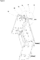
Figure 1 - is a side view of the household appliance -
Figure 2 - is a side view of the bottom of the household appliance -
Figure 3 - is an enlarged view of the dashed line A-A inFigure 2 -
Figure 4 - is an isolated view of the foot mechanisms -
Figure 5 - is an isolated view of the foot mechanism -
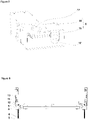
Figure 6 - is a side view of the bottom of the household appliance -
Figure 7 - is an exploded view of the foot mechanism - The following numerals are assigned to different parts demonstrated in the drawings and referred to in the present detailed description of the invention:
- 1. Household appliance
- 2. Body
- 3. Foot
- 4. Vertical shaft
- 5. Foot mechanism
- 6. Horizontal shaft
- 7. Screw gear
- 8. First gear
- 9. Second gear
- 10. Support plate
- 11. Bolt
- 12. Washer
- 13. Groove
- 14. Protrusion
- 15. Lower part
- 16. Upper part
- 17. Bore
- 18. Conduit
- The present invention relates to a household appliance (1) comprising; a body (2), a plurality of feet (3), a threaded vertical shaft (4) extending in vertical direction and originating from each of the feet (3), a foot mechanism (5) placed on to the respective feet (3) wherein the vertical shaft (4) passes through, a horizontal shaft (6) passing through and mechanically coupling the foot mechanisms (5) along the depth of the cooling appliance (1) wherein the horizontal shaft (6) is exposed on the bottom front section of the body (2), a screw gear (7) inside the foot mechanism (5), comprising a first gear (8) and a second gear (9) splined to each other and are configured to rotate around axes perpendicular to each other and into which the vertical shaft (4) and the horizontal shaft (6) are respectively and form fittingly inserted, wherein the first gear (8) abuts against and forces the foot mechanisms (5) to move upwards along the vertical shaft (4) upon rotation of the horizontal shaft (6).
- The present invention relates to a household appliance (1) further comprising; a support plate (10) extending in parallel with the vertical shaft (4) and by a bolt (11) connecting the support plate (10) to the vertical shaft (4). The household appliance (1) comprises the body (2) wherein the body (2) is placed onto the ground via the plurality of foot (3). Preferably, the feet (3) are placed under each corner of the household appliance (1). The vertical shaft (4) that is extending in a perpendicular direction is placed onto each feet (3). The foot mechanism (5) is placed onto the feet (3) and the vertical shaft (4) passes through. The vertical shaft (4) is threaded so as to be coupled with gears. The horizontal shaft (6) connects at least two foot mechanisms (5) by passing through the said foot mechanisms (5). A part of the horizontal shaft (6) is exposed on the bottom front surface of the household appliance (1) via which the user may rotate the horizontal shaft (6). The screw gear (7) is placed inside the foot mechanisms (5) and mainly comprises of two parts, the parts being; the first gear (8) and the second gear (9) wherein the said gears (8,9) are splined to each other. The first gear (8) rotates around a first axis which is perpendicular to the ground whereas the second gear (9) rotates around a second axis which is parallel to the ground. The first axis and the second axis are perpendicular to each other. The vertical shaft (4) passes through the first gear (8) and is coupled with the first gear (8) via the threads provided along its length. The horizontal shaft (6) passes through the second gear (9) and are configured to rotate together with the second gear (9) around the second axis. Upon rotating the horizontal shaft (6), the second gear (9) starts to rotate which in turn forces the first gear (8) to rotate as they are splined to each other. The first gear (8) has a canal extending through its central axis having threads configured to match with the threads provided along the length of the vertical shaft (4). The vertical shaft (4) is unmovable attached onto the foot (3) meaning that the first gear (8) climbs along the vertical shaft (4) as it rotates. The first gear (8) abuts against the foot mechanism (5) from inside and forces it to move in a vertical direction as the horizontal shaft (6) rotates. The horizontal shaft (6) extends along the depth of the household appliance (1) linearly and passes through multiple foot mechanisms (5) therefore activating multiple foot mechanisms (5) at the same time. The support plate (10) is provided so as to extend parallel with the vertical shaft (4). As the elevation of the foot mechanism (5) increases, the support plate (10) and the vertical shaft (4) remains parallel. The foot mechanism (5) is attached to the body (2) therefore as the foot mechanism (5) moves upwards so does the household appliance (1). The bolt (11) extends in between the support plate (10) and the vertical shaft (4) connecting them to each other. A major advantageous effect of using the support plate (10) is that it structurally supports the vertical shaft (4) therefore protecting the vertical shaft (4) from bending. The bolt (11) bars the foot mechanism (5) from exceeding a predetermined elevation. By this means, the foot mechanism (5) remains seated onto the vertical shaft (4) eliminating the possibility of the foot mechanism (5) getting off the vertical shaft (4).
- In another embodiment, the support plate (10) originates from the foot mechanism (5).
- In another embodiment, the support plate (10) is formed onto the body (2) of the household appliance (1). The support plate (10) is formed on the bottom side section of the body.
- In another embodiment, the bolt (11) connects the support plate (10) to the vertical shaft (4) in close vicinity of the respective upper terminal points of the support plate (10) and the vertical shaft (4). The bolt (11) is used as a means of limiting the vertical movement of the foot mechanism (5). The bolt (11) is configured to extend between the upper terminal points of the support plate (10) and the vertical shaft (4). Therefore, total elevation of the household appliance (1) can be increased.
- In another embodiment, a washer (12) placed on to the feet mechanism (5), through which the vertical shaft (4) passes through. The washer (1) upon abutting against the bolt (11) stops the movement of the foot mechanism (5).
- In another embodiment, a groove (13) extending almost along the support plate (10) in vertical direction into which a protrusion (14) originating from the washer (12) is slidably placed. The groove (13) extends along the support plate (5) forming a slit along it. The washer (12) comprises the protrusion (14) which moves slidably inside the groove (13) therefore guiding the movement of the washer (12).
- In another embodiment, the foot mechanism (5) comprises a lower part (15) and an upper part (16) each having a bore (17) arranged to be coaxial with the first gear (8) through which the vertical shaft (4) passes. The foot mechanism (5) is mainly composed of the lower part (15) and the upper part (16). Both the lower part (15) and the upper part (16) have the bore (17) configured to lie along the first axis through which the vertical shaft (4) passes through.
- In another embodiment, the upper part (16) upon placement onto the lower part (15) forms a circular conduit (18) serving as a bedding means for the second gear (9). The circular conduit (18) is in the form of a canal and extends parallel to the ground. The second gear (9) has circular ends used to rotatably attach the second gear (9) inside the circular conduit (18). The circular conduit (18), the second gear (9) and the horizontal shaft (6) are concentric and coincides with then second axis. By this means, a robust assembly is achieved.
- In a preferred embodiment the household appliance (1) is a cooling appliance.
- In the household appliance (1) of the present invention, the height of the household appliance (1) can be adjusted via the horizontal shaft (6) extending along the depth of the household appliance (1) wherein the horizontal shaft (6) is exposed on the bottom front section of the body (2) which upon being rotated forces the foot mechanisms (5) to move upwards and wherein the upward movement of the foot mechanisms (5) is limited by the bolt (11) therefore eliminating the possibility of the foot mechanism (5) getting off the vertical shaft (4). Also the support plate (10) protects the vertical shaft (4) from bending.
Claims (8)
- A household appliance (1) comprising;a body (2),a plurality of feet (3),a threaded vertical shaft (4) extending in vertical direction and originating from each of the feet (3),a foot mechanism (5) placed on to the respective feet (3) wherein the vertical shaft (4) passes through,a horizontal shaft (6) passing through and mechanically coupling the foot mechanisms (5) along the depth of the appliance (1) wherein thehorizontal shaft (6) is exposed on the bottom front section of the body (2),a screw gear (7) inside the foot mechanism (5), comprising a first gear (8) and a second gear (9) splined to each other and are configured to rotate around axes perpendicular to each other and into which the vertical shaft (4) and the horizontal shaft (6) are respectively and form fittingly inserted, wherein the first gear (8) abuts against and forces the foot mechanisms (5) to move upwards along the vertical shaft (4) upon rotation of the horizontal shaft (6),characterized bya support plate (10) extending in parallel with the vertical shaft (4) and by a bolt (11) connecting the support plate (10) to the vertical shaft (4).
- A household appliance (1) according to claim 1, characterized in that the support plate (10) originates from the foot mechanism (5).
- A household appliance (1) according to any of the preceding claims, characterized in that the bolt (11) connects the support plate (10) to the vertical shaft (4) in close vicinity of the respective upper terminal points of the support plate (10) and the vertical shaft (4).
- A household appliance (1) according to any of the preceding claims, characterized by a washer (12) placed on to the foot mechanism (5), through which the vertical shaft (4) passes through.
- A household appliance (1) according to claim 4, characterized by a groove (13) extending almost along the support plate (10) in vertical direction into which a protrusion (14) originating from the washer (12) is slidably placed.
- A household appliance (1) according to any of the preceding claims, characterized in that the foot mechanism (5) comprises a lower part (15) and an upper part (16) each having a bore (17) arranged to be coaxial with the first gear (8) through which the vertical shaft (4) passes.
- A household appliance (1) according to claim 6, characterized in that the upper part (16) upon placement onto the lower part (15) forms a circular conduit (18) serving as a bedding means for the second gear (9).
- A household appliance (1) according to claim 1, wherein the household appliance (1) is a cooling appliance.
Applications Claiming Priority (2)
| Application Number | Priority Date | Filing Date | Title |
|---|---|---|---|
| TR201820104 | 2018-12-21 | ||
| PCT/EP2019/083462 WO2020126470A1 (en) | 2018-12-21 | 2019-12-03 | A household appliance having reinforced and height adjustable feet mechanism |
Publications (2)
| Publication Number | Publication Date |
|---|---|
| EP3897337A1 EP3897337A1 (en) | 2021-10-27 |
| EP3897337B1 true EP3897337B1 (en) | 2022-09-07 |
Family
ID=68806748
Family Applications (1)
| Application Number | Title | Priority Date | Filing Date |
|---|---|---|---|
| EP19816272.9A Active EP3897337B1 (en) | 2018-12-21 | 2019-12-03 | A household appliance having reinforced and height adjustable feet mechanism |
Country Status (3)
| Country | Link |
|---|---|
| EP (1) | EP3897337B1 (en) |
| PL (1) | PL3897337T3 (en) |
| WO (1) | WO2020126470A1 (en) |
Families Citing this family (1)
| Publication number | Priority date | Publication date | Assignee | Title |
|---|---|---|---|---|
| CN113865223B (en) * | 2020-06-30 | 2023-02-17 | 青岛海尔电冰箱有限公司 | Footing adjustment system and refrigerator with same |
Citations (1)
| Publication number | Priority date | Publication date | Assignee | Title |
|---|---|---|---|---|
| EP2468136B1 (en) * | 2010-12-22 | 2014-03-19 | BSH Bosch und Siemens Hausgeräte GmbH | Household appliance, in particular free standing cooker |
Family Cites Families (4)
| Publication number | Priority date | Publication date | Assignee | Title |
|---|---|---|---|---|
| ATE369768T1 (en) * | 2003-06-04 | 2007-09-15 | Arcelik As | HOUSEHOLD APPLIANCE |
| EP2991534B1 (en) | 2013-05-03 | 2017-03-08 | Arçelik Anonim Sirketi | Household appliance having improved height profile adjustable feet |
| PL3074688T3 (en) * | 2013-11-29 | 2020-07-27 | Arçelik Anonim Şirketi | Height adjustable foot for household appliance |
| CN108049123B (en) * | 2018-01-04 | 2020-05-19 | 无锡小天鹅电器有限公司 | Footing structure and domestic appliance |
-
2019
- 2019-12-03 EP EP19816272.9A patent/EP3897337B1/en active Active
- 2019-12-03 WO PCT/EP2019/083462 patent/WO2020126470A1/en unknown
- 2019-12-03 PL PL19816272.9T patent/PL3897337T3/en unknown
Patent Citations (1)
| Publication number | Priority date | Publication date | Assignee | Title |
|---|---|---|---|---|
| EP2468136B1 (en) * | 2010-12-22 | 2014-03-19 | BSH Bosch und Siemens Hausgeräte GmbH | Household appliance, in particular free standing cooker |
Also Published As
| Publication number | Publication date |
|---|---|
| PL3897337T3 (en) | 2023-01-09 |
| EP3897337A1 (en) | 2021-10-27 |
| WO2020126470A1 (en) | 2020-06-25 |
Similar Documents
| Publication | Publication Date | Title |
|---|---|---|
| EP3897337B1 (en) | A household appliance having reinforced and height adjustable feet mechanism | |
| KR100549719B1 (en) | The height control-rail of veranda | |
| US20160360925A1 (en) | Charcoal Grill Comprising a Height-Adjustable Charcoal Rack | |
| EP3138445B1 (en) | Equipment for adjusting support feet for furniture units relative to a supporting surface | |
| KR20160069706A (en) | Bridge rail using buoyancy | |
| GB2497608A (en) | Telescopic loft ladder | |
| DE102010015968B4 (en) | Kitchen cabinet and turntable for this | |
| DE102009000189A1 (en) | Dishwasher, particularly household dishwasher, has adjustable foot, which comprises upward pointing shank supported in holding device, and extension tube is fastened on lower end area of adjustable foot | |
| US11246413B2 (en) | Furniture base and a piece of furniture comprising such a furniture base | |
| CN107795265A (en) | A kind of multifunction power maintenance ladder | |
| CH684925A5 (en) | Built-in domestic appliance with Nivellierorganen. | |
| DE3604838C2 (en) | ||
| DE102010001903B4 (en) | Lift table | |
| SE455153B (en) | DEVICE FOR CABINET EQUIPMENT | |
| CN209523996U (en) | A kind of mechanical bearing seat | |
| KR20110049008A (en) | Horizontal controller | |
| DE102014006254B4 (en) | LEVEL - EQUALIZATION DEVICE | |
| CN207379098U (en) | A kind of height adjustable solar stent | |
| EP2281611B1 (en) | Device for tilting a hoop used in basketball | |
| GB2576113A (en) | Sports goal wheel assembly, sports goal wheel system and sports goal | |
| US1928245A (en) | Counterbalancing mechanism | |
| CN108930886A (en) | A kind of adjustable type man electric support | |
| CN109057402A (en) | A kind of height tunable arrangement of the safe ladder cage of engineering | |
| DK2989271T3 (en) | HANGING UNIT AND SIMILAR COLUMN | |
| US1605855A (en) | Assiotob |
Legal Events
| Date | Code | Title | Description |
|---|---|---|---|
| STAA | Information on the status of an ep patent application or granted ep patent |
Free format text: STATUS: UNKNOWN |
|
| STAA | Information on the status of an ep patent application or granted ep patent |
Free format text: STATUS: THE INTERNATIONAL PUBLICATION HAS BEEN MADE |
|
| PUAI | Public reference made under article 153(3) epc to a published international application that has entered the european phase |
Free format text: ORIGINAL CODE: 0009012 |
|
| STAA | Information on the status of an ep patent application or granted ep patent |
Free format text: STATUS: REQUEST FOR EXAMINATION WAS MADE |
|
| 17P | Request for examination filed |
Effective date: 20210628 |
|
| AK | Designated contracting states |
Kind code of ref document: A1 Designated state(s): AL AT BE BG CH CY CZ DE DK EE ES FI FR GB GR HR HU IE IS IT LI LT LU LV MC MK MT NL NO PL PT RO RS SE SI SK SM TR |
|
| DAV | Request for validation of the european patent (deleted) | ||
| DAX | Request for extension of the european patent (deleted) | ||
| GRAP | Despatch of communication of intention to grant a patent |
Free format text: ORIGINAL CODE: EPIDOSNIGR1 |
|
| STAA | Information on the status of an ep patent application or granted ep patent |
Free format text: STATUS: GRANT OF PATENT IS INTENDED |
|
| GRAS | Grant fee paid |
Free format text: ORIGINAL CODE: EPIDOSNIGR3 |
|
| GRAA | (expected) grant |
Free format text: ORIGINAL CODE: 0009210 |
|
| STAA | Information on the status of an ep patent application or granted ep patent |
Free format text: STATUS: THE PATENT HAS BEEN GRANTED |
|
| INTG | Intention to grant announced |
Effective date: 20220718 |
|
| AK | Designated contracting states |
Kind code of ref document: B1 Designated state(s): AL AT BE BG CH CY CZ DE DK EE ES FI FR GB GR HR HU IE IS IT LI LT LU LV MC MK MT NL NO PL PT RO RS SE SI SK SM TR |
|
| REG | Reference to a national code |
Ref country code: GB Ref legal event code: FG4D |
|
| REG | Reference to a national code |
Ref country code: CH Ref legal event code: EP Ref country code: AT Ref legal event code: REF Ref document number: 1516381 Country of ref document: AT Kind code of ref document: T Effective date: 20220915 |
|
| REG | Reference to a national code |
Ref country code: IE Ref legal event code: FG4D |
|
| REG | Reference to a national code |
Ref country code: DE Ref legal event code: R096 Ref document number: 602019019409 Country of ref document: DE |
|
| REG | Reference to a national code |
Ref country code: LT Ref legal event code: MG9D |
|
| REG | Reference to a national code |
Ref country code: NL Ref legal event code: MP Effective date: 20220907 |
|
| PG25 | Lapsed in a contracting state [announced via postgrant information from national office to epo] |
Ref country code: SE Free format text: LAPSE BECAUSE OF FAILURE TO SUBMIT A TRANSLATION OF THE DESCRIPTION OR TO PAY THE FEE WITHIN THE PRESCRIBED TIME-LIMIT Effective date: 20220907 Ref country code: RS Free format text: LAPSE BECAUSE OF FAILURE TO SUBMIT A TRANSLATION OF THE DESCRIPTION OR TO PAY THE FEE WITHIN THE PRESCRIBED TIME-LIMIT Effective date: 20220907 Ref country code: NO Free format text: LAPSE BECAUSE OF FAILURE TO SUBMIT A TRANSLATION OF THE DESCRIPTION OR TO PAY THE FEE WITHIN THE PRESCRIBED TIME-LIMIT Effective date: 20221207 Ref country code: LV Free format text: LAPSE BECAUSE OF FAILURE TO SUBMIT A TRANSLATION OF THE DESCRIPTION OR TO PAY THE FEE WITHIN THE PRESCRIBED TIME-LIMIT Effective date: 20220907 Ref country code: LT Free format text: LAPSE BECAUSE OF FAILURE TO SUBMIT A TRANSLATION OF THE DESCRIPTION OR TO PAY THE FEE WITHIN THE PRESCRIBED TIME-LIMIT Effective date: 20220907 Ref country code: FI Free format text: LAPSE BECAUSE OF FAILURE TO SUBMIT A TRANSLATION OF THE DESCRIPTION OR TO PAY THE FEE WITHIN THE PRESCRIBED TIME-LIMIT Effective date: 20220907 |
|
| REG | Reference to a national code |
Ref country code: AT Ref legal event code: MK05 Ref document number: 1516381 Country of ref document: AT Kind code of ref document: T Effective date: 20220907 |
|
| PG25 | Lapsed in a contracting state [announced via postgrant information from national office to epo] |
Ref country code: HR Free format text: LAPSE BECAUSE OF FAILURE TO SUBMIT A TRANSLATION OF THE DESCRIPTION OR TO PAY THE FEE WITHIN THE PRESCRIBED TIME-LIMIT Effective date: 20220907 Ref country code: GR Free format text: LAPSE BECAUSE OF FAILURE TO SUBMIT A TRANSLATION OF THE DESCRIPTION OR TO PAY THE FEE WITHIN THE PRESCRIBED TIME-LIMIT Effective date: 20221208 |
|
| PG25 | Lapsed in a contracting state [announced via postgrant information from national office to epo] |
Ref country code: SM Free format text: LAPSE BECAUSE OF FAILURE TO SUBMIT A TRANSLATION OF THE DESCRIPTION OR TO PAY THE FEE WITHIN THE PRESCRIBED TIME-LIMIT Effective date: 20220907 Ref country code: RO Free format text: LAPSE BECAUSE OF FAILURE TO SUBMIT A TRANSLATION OF THE DESCRIPTION OR TO PAY THE FEE WITHIN THE PRESCRIBED TIME-LIMIT Effective date: 20220907 Ref country code: PT Free format text: LAPSE BECAUSE OF FAILURE TO SUBMIT A TRANSLATION OF THE DESCRIPTION OR TO PAY THE FEE WITHIN THE PRESCRIBED TIME-LIMIT Effective date: 20230109 Ref country code: ES Free format text: LAPSE BECAUSE OF FAILURE TO SUBMIT A TRANSLATION OF THE DESCRIPTION OR TO PAY THE FEE WITHIN THE PRESCRIBED TIME-LIMIT Effective date: 20220907 Ref country code: CZ Free format text: LAPSE BECAUSE OF FAILURE TO SUBMIT A TRANSLATION OF THE DESCRIPTION OR TO PAY THE FEE WITHIN THE PRESCRIBED TIME-LIMIT Effective date: 20220907 Ref country code: AT Free format text: LAPSE BECAUSE OF FAILURE TO SUBMIT A TRANSLATION OF THE DESCRIPTION OR TO PAY THE FEE WITHIN THE PRESCRIBED TIME-LIMIT Effective date: 20220907 |
|
| PG25 | Lapsed in a contracting state [announced via postgrant information from national office to epo] |
Ref country code: SK Free format text: LAPSE BECAUSE OF FAILURE TO SUBMIT A TRANSLATION OF THE DESCRIPTION OR TO PAY THE FEE WITHIN THE PRESCRIBED TIME-LIMIT Effective date: 20220907 Ref country code: IS Free format text: LAPSE BECAUSE OF FAILURE TO SUBMIT A TRANSLATION OF THE DESCRIPTION OR TO PAY THE FEE WITHIN THE PRESCRIBED TIME-LIMIT Effective date: 20230107 Ref country code: EE Free format text: LAPSE BECAUSE OF FAILURE TO SUBMIT A TRANSLATION OF THE DESCRIPTION OR TO PAY THE FEE WITHIN THE PRESCRIBED TIME-LIMIT Effective date: 20220907 |
|
| REG | Reference to a national code |
Ref country code: DE Ref legal event code: R097 Ref document number: 602019019409 Country of ref document: DE |
|
| PG25 | Lapsed in a contracting state [announced via postgrant information from national office to epo] |
Ref country code: NL Free format text: LAPSE BECAUSE OF FAILURE TO SUBMIT A TRANSLATION OF THE DESCRIPTION OR TO PAY THE FEE WITHIN THE PRESCRIBED TIME-LIMIT Effective date: 20220907 Ref country code: AL Free format text: LAPSE BECAUSE OF FAILURE TO SUBMIT A TRANSLATION OF THE DESCRIPTION OR TO PAY THE FEE WITHIN THE PRESCRIBED TIME-LIMIT Effective date: 20220907 |
|
| PLBE | No opposition filed within time limit |
Free format text: ORIGINAL CODE: 0009261 |
|
| STAA | Information on the status of an ep patent application or granted ep patent |
Free format text: STATUS: NO OPPOSITION FILED WITHIN TIME LIMIT |
|
| PG25 | Lapsed in a contracting state [announced via postgrant information from national office to epo] |
Ref country code: DK Free format text: LAPSE BECAUSE OF FAILURE TO SUBMIT A TRANSLATION OF THE DESCRIPTION OR TO PAY THE FEE WITHIN THE PRESCRIBED TIME-LIMIT Effective date: 20220907 |
|
| REG | Reference to a national code |
Ref country code: CH Ref legal event code: PL |
|
| 26N | No opposition filed |
Effective date: 20230608 |
|
| REG | Reference to a national code |
Ref country code: BE Ref legal event code: MM Effective date: 20221231 |
|
| PG25 | Lapsed in a contracting state [announced via postgrant information from national office to epo] |
Ref country code: SI Free format text: LAPSE BECAUSE OF FAILURE TO SUBMIT A TRANSLATION OF THE DESCRIPTION OR TO PAY THE FEE WITHIN THE PRESCRIBED TIME-LIMIT Effective date: 20220907 Ref country code: LU Free format text: LAPSE BECAUSE OF NON-PAYMENT OF DUE FEES Effective date: 20221203 |
|
| PG25 | Lapsed in a contracting state [announced via postgrant information from national office to epo] |
Ref country code: LI Free format text: LAPSE BECAUSE OF NON-PAYMENT OF DUE FEES Effective date: 20221231 Ref country code: IE Free format text: LAPSE BECAUSE OF NON-PAYMENT OF DUE FEES Effective date: 20221203 Ref country code: CH Free format text: LAPSE BECAUSE OF NON-PAYMENT OF DUE FEES Effective date: 20221231 |
|
| PG25 | Lapsed in a contracting state [announced via postgrant information from national office to epo] |
Ref country code: FR Free format text: LAPSE BECAUSE OF NON-PAYMENT OF DUE FEES Effective date: 20221231 Ref country code: BE Free format text: LAPSE BECAUSE OF NON-PAYMENT OF DUE FEES Effective date: 20221231 |
|
| PGFP | Annual fee paid to national office [announced via postgrant information from national office to epo] |
Ref country code: TR Payment date: 20231121 Year of fee payment: 5 Ref country code: DE Payment date: 20231214 Year of fee payment: 5 |
|
| PGFP | Annual fee paid to national office [announced via postgrant information from national office to epo] |
Ref country code: PL Payment date: 20231123 Year of fee payment: 5 |
|
| PG25 | Lapsed in a contracting state [announced via postgrant information from national office to epo] |
Ref country code: CY Free format text: LAPSE BECAUSE OF FAILURE TO SUBMIT A TRANSLATION OF THE DESCRIPTION OR TO PAY THE FEE WITHIN THE PRESCRIBED TIME-LIMIT Effective date: 20220907 |