EP3897238B1 - Aerosol generating article for use with an aerosol generating device - Google Patents
Aerosol generating article for use with an aerosol generating device Download PDFInfo
- Publication number
- EP3897238B1 EP3897238B1 EP19828257.6A EP19828257A EP3897238B1 EP 3897238 B1 EP3897238 B1 EP 3897238B1 EP 19828257 A EP19828257 A EP 19828257A EP 3897238 B1 EP3897238 B1 EP 3897238B1
- Authority
- EP
- European Patent Office
- Prior art keywords
- gel
- aerosol generating
- generating article
- fluid
- wrapper
- Prior art date
- Legal status (The legal status is an assumption and is not a legal conclusion. Google has not performed a legal analysis and makes no representation as to the accuracy of the status listed.)
- Active
Links
Images


Classifications
-
- A—HUMAN NECESSITIES
- A24—TOBACCO; CIGARS; CIGARETTES; SIMULATED SMOKING DEVICES; SMOKERS' REQUISITES
- A24F—SMOKERS' REQUISITES; MATCH BOXES; SIMULATED SMOKING DEVICES
- A24F40/00—Electrically operated smoking devices; Component parts thereof; Manufacture thereof; Maintenance or testing thereof; Charging means specially adapted therefor
- A24F40/40—Constructional details, e.g. connection of cartridges and battery parts
- A24F40/48—Fluid transfer means, e.g. pumps
-
- A—HUMAN NECESSITIES
- A24—TOBACCO; CIGARS; CIGARETTES; SIMULATED SMOKING DEVICES; SMOKERS' REQUISITES
- A24B—MANUFACTURE OR PREPARATION OF TOBACCO FOR SMOKING OR CHEWING; TOBACCO; SNUFF
- A24B15/00—Chemical features or treatment of tobacco; Tobacco substitutes, e.g. in liquid form
- A24B15/10—Chemical features of tobacco products or tobacco substitutes
- A24B15/16—Chemical features of tobacco products or tobacco substitutes of tobacco substitutes
-
- A—HUMAN NECESSITIES
- A24—TOBACCO; CIGARS; CIGARETTES; SIMULATED SMOKING DEVICES; SMOKERS' REQUISITES
- A24C—MACHINES FOR MAKING CIGARS OR CIGARETTES
- A24C5/00—Making cigarettes; Making tipping materials for, or attaching filters or mouthpieces to, cigars or cigarettes
- A24C5/01—Making cigarettes for simulated smoking devices
-
- A—HUMAN NECESSITIES
- A24—TOBACCO; CIGARS; CIGARETTES; SIMULATED SMOKING DEVICES; SMOKERS' REQUISITES
- A24C—MACHINES FOR MAKING CIGARS OR CIGARETTES
- A24C5/00—Making cigarettes; Making tipping materials for, or attaching filters or mouthpieces to, cigars or cigarettes
- A24C5/14—Machines of the continuous-rod type
- A24C5/18—Forming the rod
- A24C5/1885—Forming the rod for cigarettes with an axial air duct
-
- A—HUMAN NECESSITIES
- A24—TOBACCO; CIGARS; CIGARETTES; SIMULATED SMOKING DEVICES; SMOKERS' REQUISITES
- A24D—CIGARS; CIGARETTES; TOBACCO SMOKE FILTERS; MOUTHPIECES OF CIGARS OR CIGARETTES; MANUFACTURE OF TOBACCO SMOKE FILTERS OR MOUTHPIECES
- A24D1/00—Cigars; Cigarettes
- A24D1/02—Cigars; Cigarettes with special covers
-
- A—HUMAN NECESSITIES
- A24—TOBACCO; CIGARS; CIGARETTES; SIMULATED SMOKING DEVICES; SMOKERS' REQUISITES
- A24D—CIGARS; CIGARETTES; TOBACCO SMOKE FILTERS; MOUTHPIECES OF CIGARS OR CIGARETTES; MANUFACTURE OF TOBACCO SMOKE FILTERS OR MOUTHPIECES
- A24D1/00—Cigars; Cigarettes
- A24D1/20—Cigarettes specially adapted for simulated smoking devices
-
- A—HUMAN NECESSITIES
- A24—TOBACCO; CIGARS; CIGARETTES; SIMULATED SMOKING DEVICES; SMOKERS' REQUISITES
- A24F—SMOKERS' REQUISITES; MATCH BOXES; SIMULATED SMOKING DEVICES
- A24F40/00—Electrically operated smoking devices; Component parts thereof; Manufacture thereof; Maintenance or testing thereof; Charging means specially adapted therefor
- A24F40/20—Devices using solid inhalable precursors
-
- A—HUMAN NECESSITIES
- A24—TOBACCO; CIGARS; CIGARETTES; SIMULATED SMOKING DEVICES; SMOKERS' REQUISITES
- A24F—SMOKERS' REQUISITES; MATCH BOXES; SIMULATED SMOKING DEVICES
- A24F40/00—Electrically operated smoking devices; Component parts thereof; Manufacture thereof; Maintenance or testing thereof; Charging means specially adapted therefor
- A24F40/40—Constructional details, e.g. connection of cartridges and battery parts
- A24F40/42—Cartridges or containers for inhalable precursors
-
- A—HUMAN NECESSITIES
- A24—TOBACCO; CIGARS; CIGARETTES; SIMULATED SMOKING DEVICES; SMOKERS' REQUISITES
- A24F—SMOKERS' REQUISITES; MATCH BOXES; SIMULATED SMOKING DEVICES
- A24F40/00—Electrically operated smoking devices; Component parts thereof; Manufacture thereof; Maintenance or testing thereof; Charging means specially adapted therefor
- A24F40/40—Constructional details, e.g. connection of cartridges and battery parts
- A24F40/46—Shape or structure of electric heating means
- A24F40/465—Shape or structure of electric heating means specially adapted for induction heating
-
- D—TEXTILES; PAPER
- D21—PAPER-MAKING; PRODUCTION OF CELLULOSE
- D21H—PULP COMPOSITIONS; PREPARATION THEREOF NOT COVERED BY SUBCLASSES D21C OR D21D; IMPREGNATING OR COATING OF PAPER; TREATMENT OF FINISHED PAPER NOT COVERED BY CLASS B31 OR SUBCLASS D21G; PAPER NOT OTHERWISE PROVIDED FOR
- D21H21/00—Non-fibrous material added to the pulp, characterised by its function, form or properties; Paper-impregnating or coating material, characterised by its function, form or properties
- D21H21/14—Non-fibrous material added to the pulp, characterised by its function, form or properties; Paper-impregnating or coating material, characterised by its function, form or properties characterised by function or properties in or on the paper
- D21H21/16—Sizing or water-repelling agents
-
- D—TEXTILES; PAPER
- D21—PAPER-MAKING; PRODUCTION OF CELLULOSE
- D21H—PULP COMPOSITIONS; PREPARATION THEREOF NOT COVERED BY SUBCLASSES D21C OR D21D; IMPREGNATING OR COATING OF PAPER; TREATMENT OF FINISHED PAPER NOT COVERED BY CLASS B31 OR SUBCLASS D21G; PAPER NOT OTHERWISE PROVIDED FOR
- D21H5/00—Special paper or cardboard not otherwise provided for
- D21H5/12—Special paper or cardboard not otherwise provided for characterised by the use of special fibrous materials
- D21H5/14—Special paper or cardboard not otherwise provided for characterised by the use of special fibrous materials of cellulose fibres only
- D21H5/16—Tobacco or cigarette paper
-
- H—ELECTRICITY
- H05—ELECTRIC TECHNIQUES NOT OTHERWISE PROVIDED FOR
- H05B—ELECTRIC HEATING; ELECTRIC LIGHT SOURCES NOT OTHERWISE PROVIDED FOR; CIRCUIT ARRANGEMENTS FOR ELECTRIC LIGHT SOURCES, IN GENERAL
- H05B6/00—Heating by electric, magnetic or electromagnetic fields
- H05B6/02—Induction heating
- H05B6/10—Induction heating apparatus, other than furnaces, for specific applications
- H05B6/105—Induction heating apparatus, other than furnaces, for specific applications using a susceptor
Definitions
- the present disclosure relates to an aerosol generating article, and a gel element comprising gel, which is for use with the aerosol generating article.
- WO2017114760A discloses an aerosol generating article having a first section including a combustible heat source and an aerosol-forming substrate and a second section including a tubular element defining a recess at one end of the second section.
- the aerosol generating article further comprises an end plug located at the distal end of the aerosol generating article.
- the gel element is positioned between the fluid guide at the proximal end of the aerosol generating article and end plug positioned at the distal end of the aerosol generating article.
- the tubular guide is not necessarily, in specific embodiments, adjacent to either the end plug or the fluid guide.
- the at least one aperture is externally fluidly communicating such that ambient fluid, for example air, can pass to the gel element.
- ambient fluid for example air
- the at least one aperture corresponds in position to an aperture in the wrapper to allow ease of fluid flow into the aerosol generating article.
- the at least one aperture is a plurality of apertures.
- the aerosol generating article further comprises a susceptor.
- the at least one aperture is located in an outer passageway of the fluid guide.
- Having the at least one externally communicating aperture located in an outer passage way of the fluid guide allows distance between the gel element and the at least one externally communicating aperture. This may help prevent leaking of the gel and its contents, but also give a desired aerosol draw.
- the at least one aperture is located in the cavity between the fluid guide and the gel element.
- Having the at least one aperture located in an outer passageway of the fluid guide allows the ambient fluid to easily reach the gel element and easily mix in the cavity between the gel element and the fluid guide.
- the at least one aperture is located in the side wall of the gel element.
- Having the at least one aperture located in the side wall of the gel element allows ambient fluid to substantially travel in one direction when a negative pressure is applied to the proximal end of the aerosol generating article. Having the at least one aperture located in the side wall of the gel element allows ambient fluid to easily mix with the contents of the gel element.
- the gel element further comprises a wrapper.
- the active agent is nicotine.
- the distal end of the aerosol generating article may have an aperture.
- the aerosol generating article comprises an end plug to the distal side of the gel element.
- the end plug is of a high resistance to draw, which then enables fluid, for example ambient air, to pass through the aperture into the outer longitudinal passageway.
- fluid for example ambient air
- the fluid travels to the gel element to potentially mix with the gel or porous medium loaded with gel, or threads loaded with gel, before turning and passing through the inner longitudinal passageway of the fluid guide and exiting the aerosol generating article at the proximal end.
- the gel may be substituted for porous medium loaded with gel, or thread loaded with gel or a combination thereof.
- the aerosol generating article comprises a cavity between the distal end of the fluid guide and the proximal end of the gel element. This enables mixing of the fluid and material released from the gel element.
- the aerosol generating article comprises a wrapper.
- the wrapper is preferably made of paper for example cigarette paper.
- an additional wrapper, or alternative wrapper, for example, a water-resistant wrapper is used.
- the gel completely fills the gel element within the wrapper.
- the gel may partially fill the gel element.
- the gel is provided as a coating on an inner surface of the gel element. The advantage of only partially filling the gel element is that it leaves a fluid path, for example, for aerosol to flow into or out of the gel element.
- the gel element comprises a second gel element.
- the gel element comprises a plurality of second gel elements.
- the gel element comprises a porous medium loaded with gel.
- one or more of the second gel elements comprises porous medium loaded with gel. Where there is porous medium loaded with gel, the porous medium loaded with gel completely fills each of the plurality of second gel elements, or the porous medium loaded with gel partially fills the second gel elements.
- the longitudinal side of the second gel element comprises paper, or cardboard, or cellulose acetate.
- the gel element has an external diameter of between 5 millimetres and 12 millimetres, for example of between 5 millimetres and 10 millimetres or between 6 millimetres and 8 millimetres.
- the gel element has an external diameter of 7.2 millimetres plus or minus 10 percent.
- the gel is solid at room temperature.
- Solid in this context means that the gel has a stable size and shape and does not flow.
- Room temperature in this context means 25 degrees Celsius.
- the gel may include xanthan gum, low acyl gellan gum, and agar in a range from about 1 percent by weight to about 5 percent by weight, or about 2 percent by weight, where xanthan gum, gellan gum, and agar are substantially equal weights.
- the gel may comprise a carboxylic acid.
- the carboxylic acid may include a ketone group.
- the carboxylic acid includes a ketone group that has less than 10 carbon atoms.
- this carboxylic acid has five carbon atoms (such as levulinic acid).
- Levulinic acid may be added to the neutralize the pH of the gel. This may also assist in the gel formation that includes biopolymers (polysaccharides) such as, gellan gums (low acyl gellan gum, high acyl gellan gums), xanthan gum, especially alginates (alginic acid), agar, guar gum, and the like.
- Levulinic may also enhance a sensory profile of the gel formulation.
- the gel does not include a carboxylic acid.
- the gel comprises a gelling agent.
- the gel comprises agar or agarose or sodium alginate or Gellan gum, or a mixture thereof.
- the gel comprises water, for example, the gel is a a hydrogel.
- the gel is non-aqueous.
- the gel comprises a solid tobacco material that releases flavour compounds when heated.
- the solid tobacco material is, for example, one or more of: powder, granules, pellets, shreds, spaghettis, strips or sheets containing one or more of: plant material, such as herb leaf, tobacco leaf, fragments of tobacco ribs, reconstituted tobacco, homogenised tobacco, extruded tobacco and expanded tobacco.
- the gel comprises other flavours, for example menthol.
- Menthol can be added either in water or in the aerosol former prior to the formation of the gel.
- the gel comprises 2 percent by weight nicotine, 70 percent by weight glycerol, 27 percent by weight water and 1 percent by weight agar.
- the wrapper is stiff, or rigid, to aid structure of the gel element. It is foreseen that the gel used in the present invention is semi-solid, able to retain a shape, especially in use. However, the present invention is not limited to solid gels. More fluid gels, gels with a higher viscosity than those of solid gels, can also be used with embodiments of the present invention. Having a wrapper that itself, is able to retain the gel element structure is therefore beneficial, although not necessary.
- the longitudinal side of second gel element may be rigid, or stiff. Having the wrapper or longitudinal side of the second tubular element, or both, the wrapper and longitudinal side of the second gel element stiff or indeed rigid, may aid structure of the gel element, but may also aid manufacture.
- the wrapper has a thickness of between about 50 micrometres and 150 micrometres.
- the wrapper is water-resistant.
- the longitudinal side of the second gel element is water-resistant.
- This water-resistant property, of either the wrapper or longitudinal side of the second gel element may be achieved by using a water-resistant material, or by treating the material of the wrapper or longitudinal side of the second gel element. It may be achieved by treating one side or both sides of the wrapper or longitudinal side of the second gel element.
- Being water-resistant would assist in not losing structure, stiffness or rigidity. It may also assist in preventing leaks of gel or liquid, especially when gels of a fluid structure are used.
- a gel element comprising a wrapper that forms a first longitudinal channel, the gel element further comprising a porous medium loaded with gel, the porous medium loaded with gel further comprising an active agent.
- the longitudinal side of the second gel element comprises paper, or cardboard, or cellulose acetate.
- the porous medium loaded with gel is positioned between the second gel element and the wrapper that forms the first longitudinal channel. In some alternative embodiments, where there is a first and second gel element, gel is positioned between the second gel element and the wrapper that forms the first longitudinal channel.
- the outer longitudinal passageway of the aerosol generating article comprises one aperture or a plurality of apertures.
- the aperture may be any aperture, slit, hole, or passageway to allow fluid, for example ambient air, to pass through, and into the aerosol generating article. This allows fluid from external of the aerosol generating article to be drawn in. In use this may be external fluid, for example air that is drawn into the aerosol generating article through the apertures into the outer longitudinal passageways first, before being drawn to other parts of the aerosol generating article.
- the apertures are evenly spaced around the circumference of the aerosol generating article, for example there are 10 or 12 apertures. Having the apertures evenly spaced helps give a smooth flow of fluid.
- the inner longitudinal passageway of the inner region of the fluid guide comprises a restrictor.
- the restrictor is located at, or near to, the proximal end of the fluid guide. In some embodiments the restrictor is located at, or near to, the downstream end of the fluid guide.
- the restrictor if present, may however be positioned in the middle region of the inner longitudinal passageway of the fluid guide, or the outer longitudinal passageway. The restrictor could also be positioned, near to, or at the distal end of the inner longitudinal passageway.
- the restrictor may be positioned at, or near to, the upstream end of the inner longitudinal passageway. More than one restrictor may be used in the inner longitudinal passageway, or in the outer longitudinal passageway, of the fluid guide.
- an aerosol generating device comprising a receptacle configure to receive the distal end of the aerosol generating article as described herewith.
- the porous medium loaded with gel comprises a sheet material, for example, cotton or cellulose acetate.
- a porous medium loaded with gel is that the gel is retained within the porous medium, and this may aid manufacturing, storage or transport of the gel. It may assist in keeping the desired shape of the gel, especially during manufacture, transport, or use.
- the porous medium used in the present invention may be crimped or shredded. In specific embodiments the porous medium comprises crimped porous medium. In alternative embodiments the porous medium comprises shredded porous medium. The crimping or shredding process can be before or after loading with gel.
- the porous medium may be a thread.
- the thread may comprise for example cotton, paper or acetate tow.
- the thread may also be loaded with gel like any other porous medium.
- An advantage of using a thread as the porous medium is that it may aid ease of manufacturing.
- the thread may be preloaded with gel before being used in the manufacture of the gel element or the thread may be loaded with gel in the assembly of the gel element.
- the thread may be loaded with gel by any known means.
- the thread may be simply coated with gel, or the thread may be impregnated with gel.
- the threads may be impregnated with gel and stored ready for use to be included in the assembly of a gel element.
- the thread undergoes the loading process in the manufacture of the gel element loaded with gel.
- the gel comprises an active agent.
- the active agent is as herein described.
- aerosol generating article is used to describe an article able to generate, or release, an aerosol.
- aerosol generating device is a device to be used with an aerosol generating article to enable the generation, or release, of an aerosol.
- aerosol generating substance is used to describe a substance capable of generating or releasing an aerosol.
- aperture is used to describe any aperture, slit, hole or opening.
- the term "cavity” is used to describe any void or space at least partially enclosed in a structure.
- the cavity is the partially enclosed space (in some embodiments) between the fluid guide and the tubular element.
- an inner longitudinal cross-sectional area that is "constricted" from a first location to a second location is used to indicate that the inner longitudinal cross-sectional area reduces in diameter from the first location to the second location.
- a restrictive is used to describe a narrowing in a fluid passageway or a change of cross-sectional area in a fluid passageway.
- the term “diameter” or “width” is a maximum transverse dimension of the gel element, aerosol generating article or aerosol generating device, a portion or a part of thereof, any of the gel element, aerosol generating article or aerosol generating device.
- the “diameter” is a diameter of an object having a circular transverse section or is the length of the diagonal width of an objection having a rectangular cross section.
- essential oil is used to describe an oil having the characteristic odour and flavour of the plant from which it is obtained.
- fluid guide is used to describe an apparatus or component that can alter the fluid flow. Preferably this is guiding or directing the fluid flow path of a generated or released aerosol.
- the fluid guide is likely to cause mixing of the fluid. It can aid speeding up of the fluid as it travels though the fluid guide, when the passageway narrows in cross-sectional area, or it can aid slowing down of the fluid as it travels along the passageway when the cross-section of the passageway broadens.
- the term "gathered” is used to describe a sheet that is convoluted, folded, or otherwise compressed or constricted substantially transversely to the longitudinal axis of the aerosol generating article or gel element.
- impermeable is used to describe an item, for example a barrier, that fluid does not substantially or easily pass through.
- the term "mandrel” is used to describe a shaft on which another material is forged or shaped.
- Mints is used to refer to plants of the genus Mentha.
- the term “plug” is used to describe a component, segment or element, for use in an aerosol generating article.
- the term “end plug” is used to describe the furthest most distal component or plug of the aerosol generating article, at the distal end of the aerosol generating article. Preferably this end plug will have a high Resistance to Draw (RTD).
- RTD Resistance to Draw
- protogenic refers to a group that is able to donate a hydrogen or a proton in a chemical reaction.
- High Resistance to Draw is used to describe the resistance for fluid, for example gas, to be drawn through a material.
- high resistance to draw means is greater than 200 "mm WG or “millimetres of water gauge” and is measured in accordance with ISO 6565:2002.
- sheet material is used to describe a generally planar, laminar element in which its width and length are substantially greater than its thickness.
- shredded is used to describe something that is finely cut.
- the term "stiff” is used to describe that an item is rigid enough, or stiff enough, to resist changing shape, or stiff enough to generally resist deforming shape under normal use. This includes that it may be resilient such that if deformed it can largely return to its original shape. Likewise, the term “rigid” as used herein, describes that the item is resistant to bending or being forced out of shape, generally able to maintain its shape, especially under normal use.
- the term "susceptor” is used to describe a heating element, any material able to absorb electromagnetic energy and convert it to heat.
- the susceptor or heat element may assist in transferring thermal energy to the gel, heating up the gel, to assist in releasing materials from the gel.
- the term "gel element" is used to describe a component suitable for use in an aerosol generating article.
- the gel element may be longer in longitudinal length than in width but not necessarily as it may be one part of a multi- component item that ideally will be longer in its longitudinal length then its width.
- the gel element is cylindrical but not necessarily.
- the gel element may have an oval, polygonal like triangular or rectangular or random cross section.
- the gel element need not be hollow.
- elements of the aerosol-generating article located between the proximal end and the distal end can be described as being upstream of the proximal end, or, alternatively, downstream of the distal end.
- the distal end of the aerosol generating article may be either upstream or downstream, depending on the respective reference point.
- water-resistant is used to describe material, for example a wrapper, or longitudinal side of a second gel element, that does not allow water to pass through it easily, or, is not easily damaged by water.
- the water-resistant material is able to resist water penetration.
- the gel element will comprise at least 150 mg of gel.
- the gel, comprising an active agent comprises an aerosol former, such as glycerol.
- an aerosol former typically for example, the gel comprising an active agent comprises between 60 percent and 95 percent by weight of glycerol, such as between 80 percent and 90 percent by weight of glycerol.
- the active agent may be a flavour.
- the active agent comprises a flavourant.
- the gel may include a flavourant.
- flavourants may be present at one or more other locations of the article.
- the flavourant may impart a flavour to contribute to the taste of the fluid or aerosol generated by the article.
- a flavourant is any natural or artificial compound that affects the organoleptic quality of the aerosol.
- Plants that can be used to provide flavourants include but are not limited to, those belonging to the families, Lamiaceae (for example mints), Apiaceae (for example anise, fennel), Lauraceae (for example laurels, cinnamon, rosewood), Rutaceae (for example citrus fruits), Myrtaceae (for example anise, myrtle), and Fabaceae (for example liquorice).
- Non-limiting examples of sources of flavourants include mints such as peppermint and spearmint, coffee, tea, cinnamon, clove, ginger, cocoa, vanilla, eucalyptus, geranium, agave, and juniper; and combinations thereof.
- flavourants are essential oils, or a mixture of one or more essential oils. Suitable essential oils include, but are not limited to, eugenol, peppermint oil and spearmint oil.
- the flavourant comprises menthol, eugenol, or a combination of menthol and eugenol.
- the flavourant further comprises anethole, linalool, or a combination thereof.
- flavourants comprise Herbaceous material.
- Herbaceous material includes herb leaf or other herbaceous material from herbaceous plants including, but not limited to, mints, such as peppermint and spearmint, lemon balm, basil, cinnamon, lemon basil, chive, coriander, lavender, sage, tea, thyme and caraway.
- Suitable types of mint leaf may be taken from plant varieties including but not limited to Mentha piperita, Mentha arvensis, Mentha niliaca, Mentha citrata, Mentha spicata, Mentha spicata crispa, Mentha cordifolia, Mentha longifolia, Mentha pulegium, Mentha suaveolens, and Mentha suaveolens variegata.
- a flavourant can include tobacco material.
- the gel comprises approximately; 2 percent by weight nicotine, 70 percent by weight glycerol, 27 percent by weight water and 1 percent by weight agar. In another example, the gel comprise 65 percent by weight glycerol, 20 percent by weight water, 14.3 percent by weight solid powdered tobacco and 0.7 percent by weight agar.
- the fluid guide may have two distinct regions, for example an outer region with an outer longitudinal passageway and an inner region with an inner longitudinal passageway. Therefore, the outer longitudinal passageway runs lengthwise near to the circumference of the fluid guide, and the inner fluid passageway runs lengthwise near to the core, or centre, of the cross-sectional along the lengthwise axis.
- ambient air enters through the apertures, in the wrapper and apertures in the fluid guide, to the outer longitudinal passageway (of the fluid guide) towards the distal end of the aerosol generating article and in the area of the gel element comprising gel comprising active agent.
- the fluid will make contact with the gel comprising an active agent, to generate, or release an aerosol of mixed fluid comprising fluid from external of the aerosol generating article, and material released from the gel comprising an active agent, or agents. Fluid then travels along the inner longitudinal passageway, of the fluid guide, towards the proximal end of the aerosol generating article. It is foreseen that the outer and inner longitudinal passageways are separated by a barrier.
- the barrier may be impermeable to fluid or resistant to fluids passing through it, and thus is able to bias the fluid to the distal end.
- the outer longitudinal passageway of the fluid guide comprises an aperture that fluidly communicates with an exterior of the fluid guide, and preferably an exterior of the article. It is also foreseen that the outer longitudinal passageway is blocked at its proximal end such that, in use, fluid received from an exterior of the aerosol generating article predominantly flows towards the distal end of the fluid guide.
- the outer longitudinal passageway, of the fluid guide has apertures at or near the proximal end but then is only open at its distal end.
- the inner longitudinal passageway, of the fluid guide is open at both its proximal end and its distal end, although it may have various flow restriction elements between its proximal and distal ends.
- the barrier separating the inner and outer longitudinal passageways, of the fluid guide forces the fluid that enters the outer longitudinal passageway to travel to the distal end of the outer longitudinal passageway and towards the gel element preferably comprising gel comprising an active agent. This, brings the fluid in contact with the gel element preferably comprising gel comprising an active agent.
- the outer longitudinal passageway, of the fluid guide may be one passageway or more than one passageway.
- the outer longitudinal passageway may be within the fluid guide or may be one or more passageways on the outer surface of the fluid guide with the fluid guide forming a partial wall of the outer longitudinal passageway and the wrapper forming another partial wall to the outer longitudinal passageway.
- the outer or inner longitudinal passageways of the fluid guide may comprise porous material for example foam, in particular reticulated foam, such that the passageways traverse through the porous material.
- the fluid guide comprises a porous material, for example foam.
- the porous material may allow passage of the fluid while still maintaining its shape. These materials are easy to shape and therefore may assist in manufacture of the aerosol generating article.
- the outer longitudinal passageway may extend substantially around the interior of a wrapper. In some embodiments, the passageway may extend less than fully around the interior of a wrapper.
- the aerosol generating article for use with an aerosol generating device described herein may provide one or more advantages relative to currently available or previously described aerosol generating articles.
- the aerosol generating article including the fluid guide and inner and outer fluid passageways of the fluid guide, allows for efficient transfer of aerosol generated from the gel element comprising gel preferably comprising an active agent.
- the gel comprising an active agent is less likely to leak form the aerosol generating article than a liquid element comprising an active agent.
- the aerosol generating article may include a mouth end (the proximal end); and a distal end.
- the distal end is received by an aerosol generating device having a heating element configured to heat the distal end of the aerosol generating article.
- the gel element comprising gel preferably comprising an active agent, is preferably disposed in proximity to the distal end of the aerosol generating article.
- the aerosol generating device may therefore heat the gel element comprising gel preferably comprising an active agent in the aerosol generating article to generate an aerosol comprising the active agent.
- the aerosol generating article, or portions of the aerosol generating article, containing the gel element, preferably comprising gel comprising an active agent may be single-use aerosol generating articles or multi-use aerosol generating articles.
- portions of the aerosol generating articles are re-usable, and portions are disposable after a single use.
- the aerosol generating articles may include a mouthpiece that may be reusable and a single use portion that contains the gel element comprising the gel and active agent for example further comprising nicotine.
- the reusable portions may be removable from the single use portions.
- the aerosol generating article comprises a wrapper.
- the aerosol generating article has an open end, the proximal end; and a distal end, which may be open or closed in different specific embodiments.
- the gel element preferably comprising gel comprising an active agent, which optionally comprises nicotine, is preferably disposed in proximity to the distal end of the aerosol generating article. Applying a negative pressure on the open, proximal end causes material from the gel element, preferably comprising gel comprising an active agent, to be released.
- the aerosol generating article defines at least one aperture between the proximal end and the distal end.
- the aperture By spacing the aperture from the distal end of the aerosol generating article, the aperture is separated from the gel element comprising gel, reducing the likelihood of leakage of the gel through the aperture. Furthermore, by providing a passageway, for example the outer longitudinal passageway, for airflow from the aperture to the gel element comprising gel, the fluid from the aperture may be directed towards the gel and the fluid guide may act as a further obstacle between the gel and the aperture. The advantage of this is to further reduce the likelihood of leakage of the gel element through the aperture.
- the inner longitudinal passageway of the fluid guide provides a pathway for fluid, for example air, and material or vapour generated, or released from the gel element, to be drawn out of the aerosol generating article through the open, proximal end.
- the pathway provided by the inner longitudinal passageway of the fluid guide may have an inner longitudinal flow cross-sectional area that is varied along the length of the inner longitudinal passageway to alter the flow of aerosol generated, or released, from the gel element, from the distal end of the aerosol generating article to the open, proximal end of the aerosol generating article.
- the aerosol generating article comprises a fluid guide.
- the aerosol generating article and the fluid guide, or portions thereof, may be formed as a single part or separate parts.
- An advantage of the fluid guide and aerosol generating article being integrally formed as one single part, is the ease of manufacturing just one part rather than multiple parts and then subsequently assembling these multiple parts within the aerosol generating article.
- the aerosol generating article is a multi-component structure requiring multiple components to be assembled together then this has an advantage that different components can be more easily changed without having to change the entire manufacturing process.
- the fluid guide may be formed as a single part or separate parts for the same reasons - ease of manufacturing if integrally manufactured as one piece, but able to adapt more easily if assemble components of the fluid guide.
- the fluid guide is disposed in the aerosol generating article and has a proximal end, a distal end, and an inner longitudinal passageway between the distal end and the proximal end.
- the inner longitudinal passageway of the fluid guide has an inner cross-sectional area.
- Ventilated fluid passing through the apertures enter the aerosol generating article and flows in the distal direction, along the outer longitudinal passageway.
- the fluid makes contact with the gel element preferably comprising gel, comprising an active agent, and preferably generates, or releases, an aerosol containing the active agent, or other contents of the gel element.
- the angle beta ( ⁇ ) is preferably less than 60 degrees, more preferably less than 45 degrees, and most preferably less than 15 degrees, either in the clockwise direction or counter-clockwise direction.
- the mixing of any fluid generated from the article and the ventilated fluid may be enhanced in the case where the angle beta ( ⁇ ) is offset from the radius.
- all of the passageways may be directed in a clockwise direction or in a counter-clockwise direction, or some of the passageways are directed in the clockwise direction and some of them are directed in a counter-clockwise direction.
- a single opening or passageway may be provided in the fluid guide.
- two or more spaced apart openings or passageways may be provided in the fluid guide.
- a pair of substantially opposed passageways is provided. Having more than one passageway is advantageous to allow increased control of the fluid flow through the passageways. Having one passageway is advantageous for ease of manufacturing.
- the openings or passageways may have the same open area as each other or different open areas. Having an equal open area for two or more passageways all the same area is advantageous to enable even flow of fluid through all the passageways. However, having two or more passageways with different open areas is advantageous to create turbulence of the fluid as it passes though the two or more passageways.
- the passageways may be positioned at substantially the same position along the length of the fluid guide, or at different longitudinal positions to each other. Having two or more passageways at the same position along the length of the fluid guide is advantageous to enable even flow of fluid through all the passageways. Having two or more passageways at different longitudinal positions to each other is advantageous to create turbulence of the fluid as it passes though the two or more passageways.
- the inner longitudinal cross-sectional area of the first portion of the inner longitudinal passageway may expand from a location closer to the distal end of the fluid guide to a location closer to the proximal end of the fluid guide to cause the fluid to decelerate as it flows from the distal end towards the proximal end.
- the inner longitudinal cross-sectional area of the first portion may expand from the distal end of the second portion to the proximal end of the second portion of the fluid guide.
- the distal end of the second portion of the inner longitudinal passageway (the location closer to the distal end of the fluid guide) may have an inner diameter less than the proximal end of the second portion (the location closer to the proximal end of the fluid guide).
- the constriction is non-uniform.
- the expansion of the inner longitudinal passageway is stepped, the cross-sectional area of the inner longitudinal passageway constricts in discrete increments, or steps, from the distal end to the proximal end.
- a non-uniform reduction in the cross-sectional area of the inner longitudinal passageway is advantageous in creating turbulence of the fluid as it passes along the fluid guide.
- the aerosol generating article comprises at least one outer longitudinal passageway in communication with an aperture of the wrapper.
- the passageway is formed, at least in part, by the wrapper, where a wrapper is present.
- the passageway directs fluid (for example ambient air) from the aperture towards the gel element comprising an active agent.
- the outer longitudinal passageway is formed in an outer portion of the fluid guide under an interior surface of the wrapper.
- the aerosol generating article may comprise more than one outer longitudinal passageway.
- the aerosol generating article comprises from 2 to 20 outer longitudinal passageways in the outer portion of the fluid guide.
- the article may comprise 6 to 14 outer longitudinal passageways, typically 10 to 12 passageways. A different number of passageways allows for a different aerosol flow dynamic.
- the width of the outer longitudinal passageways are, for example, between 0.5 millimetres and 2 millimetres, typically between 0.75 millimetres and 1.8 millimetres.
- the distal end of the longitudinal passageways may be positioned a distance from the distal end of the aerosol generating article such that fluid that enters the aperture of the outer longitudinal passageways may make contact with the gel element and enable an aerosol to be generated, or released, from the gel.
- the aerosol generated, or released, at the gel element may pass through the inner longitudinal passageway of the fluid guide to the proximal end of the aerosol generating article.
- At least 5 percent of the fluid that flows through the aerosol generating article contacts the gel element and gel preferably comprising an active agent. More preferably, at least 25 percent of the air that flows through the article contacts the gel element comprising an active agent.
- the aerosol generating article is generally cylindrical. This easily enables a smooth flow of the aerosol.
- the aerosol generating article may have an outer diameter, for example, between 4 millimetres and 15 millimetres, between 5 millimetres and 10 millimetres, or between 6 millimetres and 8 millimetres.
- the aerosol generating article may have a length, for example, between 10 millimetres and 60 millimetres, between 15 millimetres to 50 millimetres, or between 20 millimetres and 45 millimetres.
- aerosol generating articles according to the present invention comprise an aperture at a location along the outer longitudinal passageway.
- the aperture is at a location upstream of the restrictor.
- the aperture will be provided as a row or rows of apertures through the wrapper, or fluid guide, or both the fluid guide and the wrapper, and allow fluid to be drawn into the aerosol generating article.
- the fluid is first drawn through the apertures then the outer longitudinal passageway(s), then towards the distal end of the aerosol generating article where the fluid can contact the gel element, and preferably the gel within the gel element, preferably the gel comprising an active agent, before passing along the inner longitudinal passageway and through, if present in that embodiment, a restrictor.
- a wrapper provides strength and structural rigidity for the aerosol generating article.
- paper or cardboard is used for the wrapper and a high degree of stiffness is desired it preferably has a basis weight greater than 60 grams per square metre.
- One such wrapper may provide high structural rigidity.
- the wrapper may resist deformation on the outside of the aerosol generating article at the location where, if present, the restrictor is embedded within the aerosol generating article, or in other locations for example, in cavities (if present) where there is less structural support.
- the gel element wrapper comprises a metal layer.
- the metal layer may be used to concentrate an externally applied energy to heat the tubular member, for example, the metal layer may act as susceptor for an electromagnetic field, or collect radiation energy supplied by an external heat source. If an internal heat source is present, the metal layer may prevent heat from leaving the gel element through the wrapper, thus increasing the efficiency of the heating. It may also provide for a uniform distribution of heat along the periphery of the tubular member.
- the aerosol generating article comprises a seal between an exterior of the fluid guide and an interior of a wrapper.
- the wrapper may then be securely attached to the fluid guide. It need not create a fluid impermeable seal.
- the aerosol generating article defines a fluid path through which fluid can flow.
- a negative pressure is provided at the mouth end (proximal end) of the aerosol generating article
- fluid enters the aerosol generating article through an aperture in the wrapper (or fluid guide, or both), then flows through the outer longitudinal passageway towards the distal end of the aerosol generating article.
- aerosol optionally generated by heating of the gel element comprising an active agent.
- the fluid with entrained aerosol may then flow through the inner longitudinal passageway of the fluid guide and through the open mouth end of the aerosol generating article.
- the aerosol generating device may comprise a temperature sensor, such as a thermocouple, operably coupled to the control electronics to control the temperature of the heating elements.
- the temperature sensor may be positioned in any suitable location. For example, the temperature sensor may be in contact or in proximity to the heating element.
- the sensor may transmit signals regarding the sensed temperature to the control electronics, which may adjust heating of the heating element to achieve a suitable temperature at the sensor.
- the portion of the aerosol generating article comprising the gel element is positioned in the aerosol generating device such that the heating element or heating elements that generate electromagnetic radiation for the induction heating are in proximity to the portion of the aerosol generating article that comprises the gel element.
- the heating elements of the aerosol generating device are in proximity to the gel within the aerosol generating article, when positioned in the aerosol generating device.
- the gel within the gel element may initially be separated from the aerosol received into the gel element, and may be released to become entrained into the aerosol in response to the rupturing of a frangible partition.
- a plurality of portions of the gel may each be sealed behind a respective, frangible partition, and rupturing an appropriate number of frangible partitions is required to achieve a desired level of entrainment of active agent into the aerosol received into the gel element, in use.
- the wrapper and particularly the wrapper region adjacent the gel element preferably comprising gel comprising an active agent, has a water contact angle of at least 90 degrees, for example at least 95 degrees, at least 100 degrees, at least 110 degrees, at least 120 degrees, at least 130 degrees at least 140 degrees, at least 150 degrees, at least 160 degrees, or at least 170 degrees.
- Hydrophobicity is determined by utilizing the TAPPI T558 om-97 test and the result is presented as an interfacial contact angle and reported in "degrees" and can range from near zero degrees to near 180 degrees. Where no contact angle is specified along with the term hydrophobic, the water contact angle is at least 90 degrees.
- the hydrophobic reagent includes an acyl halide, a fatty acid halide, such as, a fatty acid chloride including palmitoyl chloride, stearoyl chloride or behenoyl chloride, a mixture thereof, for example.
- a fatty acid chloride including palmitoyl chloride, stearoyl chloride or behenoyl chloride, a mixture thereof, for example.
- the in-situ reaction between fatty acid chloride and cellulosic material forming the continuous sheet results in fatty acid esters of cellulose and hydrochloric acid.
- hydrophobic reagent or group Any suitable method can be utilized to chemically bond the hydrophobic reagent or group to the cellulosic material forming the hydrophobic tube region.
- the hydrophobic group is covalently bonded to the cellulosic material by diffusion of a fatty acid halide on its surface without using a solvent.
- the hydrophobic reagent can be applied to the cellulosic material of the wrapper paper in any useful amount or basis weight.
- the basis weight of the hydrophobic reagent is less than 3 grams per square meter, less than 2 grams per square meter, or less than 1 gram per square meter or in a range from 0.1 to 3 grams per square meter, from 0.1 to 2 grams per square meter, or from 0.1 to 1 gram per square meter.
- the hydrophobic reagent can be applied or printed on the wrapper paper surface and define a uniform or non-uniform pattern.
- the applying step can be carried out by loading the fatty acid halide in liquid form onto a solid support, such as a brush, a roller, or an absorbent or non-absorbent pad, and then contacting the solid support with a surface of the paper.
- a solid support such as a brush, a roller, or an absorbent or non-absorbent pad
- the fatty acid halide can also be applied by printing techniques, such as gravure, flexography, ink jet, heliography, by spraying, by wetting, or by immersion in a liquid comprising the fatty acid halide.
- the applying step can deposit discrete islands of reagent forming a uniform or non-uniform pattern of hydrophobic areas on the surface of the wrapper paper.
- the uniform or non-uniform pattern of hydrophobic areas on the wrapper paper can be formed of at least 100 discrete hydrophobic islands, at least 500 discrete hydrophobic islands, at least 1000 discrete hydrophobic islands, or at least 5000 discrete hydrophobic islands.
- the discrete hydrophobic islands can have any useful shape such as for example a circle, rectangle or polygon.
- the discrete hydrophobic islands can have any useful average lateral dimension. In many embodiments the discrete hydrophobic islands have an average lateral dimension in a range from 5 to 100 micrometres, or in a range from 5 to 50 micrometres.
- a gas stream can also be applied to the surface of the wrapper.
- the hydrophobic surface can be formed by printing reagent along the length of the cellulosic material. Any useful printing methods can be utilized such as gravure, ink jet and the like. Gravure printing is preferred.
- the reagent can include any useful hydrophobic groups that can be chemically, for example, covalently, bonded to the wrapper, in particular to cellulosic material or pendent groups of the cellulosic material, of the wrapper.
- the aerosol generating article comprises a susceptor.
- the gel element comprises a susceptor.
- the susceptor is elongated and is arranged longitudinally within the gel element
- the susceptor is in thermal contact with the gel or porous material loaded with gel. This may aid heat transfer from the heating element in the aerosol generating device to, and through, the aerosol generating article, preferably through the gel element to the susceptor, and therefore the gel or porous medium loaded with gel, if in the proximity of the susceptor.
- the elongate susceptor may be made of a specific material and may have specific dimensions that allow energy dissipation of between 1 Watt and 8 Watt when used in conjunction with a particular conductor that generates a fluctuating magnetic field of known frequency and known field strength.
- the elongate susceptor, of the present invention is part of a consumable item, and thus is only used once.
- the flavour of a sequence of aerosol-generating articles may be more consistent due to the fact that a fresh susceptor acts to heat each aerosol generating article.
- the requirement for cleaning of the aerosol-generating device is significantly easier for devices with reusable heating elements and may be achieved without damage to a heat source.
- the lack of a heating element that needs to penetrate an aerosol-forming substrate means that insertion and removal of an aerosol-generating article into an aerosol-generating device is less likely to cause inadvertent damage to either the aerosol generating article or the aerosol generating device.
- the overall aerosol-generating system is, therefore, robust.
- the aerosol-generating article is designed to engage with an electrically-operated aerosol-generating device comprising an induction heating source.
- the induction heating source or inductor, generates the fluctuating electromagnetic field for heating a susceptor located within the fluctuating electromagnetic field.
- the aerosol-generating article engages with the aerosol generating device such that the susceptor is located within the fluctuating electromagnetic field generated by the inductor.
- the susceptor may be formed from any material that can be inductively heated to a temperature sufficient to generate an aerosol from the aerosol-forming substrate.
- the susceptor comprises a metal or carbon.
- a preferred susceptor may comprise a ferromagnetic material, for example ferritic iron, or a ferromagnetic steel or stainless steel.
- the susceptor comprises aluminium.
- Preferred susceptors may be formed from 400 series stainless steels, for example grade 410, or grade 420, or grade 430 stainless steel. Different materials will dissipate different amounts of energy when positioned within electromagnetic fields having similar values of frequency and field strength. Thus, parameters of the susceptor such as material type, length, width, and thickness may all be altered to provide a desired power dissipation within a known electromagnetic field.
- the susceptors are heated to a temperature in excess of 250 degrees Celsius. However, preferably the susceptors are heated less than 350 degrees Celsius to prevent burning of material in contact with the susceptor.
- Suitable susceptors may comprise a non-metallic core with a metal layer disposed on the non-metallic core, for example metallic tracks formed on a surface of a ceramic core.
- the susceptor may be in the form of a powder, for example, a metal powder.
- the powder may be in the gel, or the wrapper, or spaced between the gel and the wrapper, or combinations thereof.
- Figures 3-12 and 35-44 concern embodiments of the invention, the examples of figures 1, 2 , 13-34 , 45 and 46 are not according to the invention and are present for illustration purposes only.
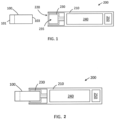
- FIGS. 1 and 2 show examples of an aerosol generating article, of the present invention, in use with an aerosol generating device, of the present invention. These aerosol generating articles and devices are suitable for use with the gel elements of the present invention.
- the figures not all components are necessarily shown or labelled.
- the drawings are for illustrative purposes to understand the invention. The drawings may not be to scale.
- Figures 1 to 6 show a longitudinal cross-sectional cut away view of an aerosol generating articles 100 .
- the Figures 1 to 6 show a view of an aerosol generating article 100 cut in half longitudinally.
- the aerosol generating article is tubular. If one viewed a whole end face of the aerosol generating article 100 of Figure 1 to 6 , either the proximal end 101 or distal end 103 it would be circular.
- the gel element 500 of Figures 1 to 6 may be cylindrical or tubular.
- the gel element 500 is a, possibly tubular, component of the tubular aerosol generating article 100 of the Figure 1 to 6 embodiments.
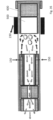
- FIGs 1-2 illustrate an example of an aerosol generating article 100 and aerosol generating device 200.
- the aerosol generating article 100 has a proximal or mouth end 101 and a distal end 103.
- the distal end 103 of the aerosol generating article 100 is received in a receptacle 220 of the aerosol generating device 200.
- the aerosol generating device 200 includes a wrapper 110 defining the receptacle 220, which is configured to receive the aerosol generating article 100.
- the aerosol generating device 200 also includes a heating element 230 that forms a cavity 235 configured to receive the aerosol generating article 100, preferably by interference fit.
- the heating element 230 may comprise an electrically resistive heating component.
- the device 200 includes a power supply 240 and control electronics 250 that cooperate to control heating of heating element 230.
- the heating mechanism could be by conduction heating where the heat is transferred from the heating element 230 of the aerosol generating device 200 to the aerosol generating article 100. This can take place easily when the aerosol generating article 100 is positioned in the receptacle 220 of the aerosol generating device 200 and the distal end 103 (which is preferably the end where the gel element 500 comprising gel is located) and thus the aerosol generating article 100 is in contact with the heating element 230 of the aerosol generating device 200.
- the heating element comprises a heating blade that protrudes from the aerosol generating device 200 and is suitable for penetrating into the aerosol generating article 100 to make direct contact with the gel 124 of the gel element 500.
- the drawings are for illustrative purposes to explain the invention and may not be to scale.
- the gel element 500 is shown in Figures 3a and Figure 3b to illustrate the gel element in an aerosol generating article but the features of the aerosol generating article 100 are optional to the embodiment shown of the gel element and should not be seen as essential features of the gel element 500.
- the second portion 420 defines a second portion of the inner longitudinal passageway 430, which extends from the distal end 423 of the second portion 420 to the proximal end 421 of the second portion 420.
- the third portion 435 defines a third portion of the inner longitudinal passageway 430, which extends from the distal end 433 of the third portion to the proximal end 431 of the third portion.
- the third portion 435 has a substantially constant inner diameter from the proximal end 431 to the distal end 433.
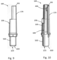
- the article depicted in Figure 4 includes a wrapper 110 that defines an open, proximal end 101 and a distal end 103, with an end plug 600 of a high resistance to draw.
- a gel element 500 comprising a gel comprising an active agent is disposed in the distal end 103 of the aerosol generating article. Aerosol released from the gel comprising an active agent, when heated may enter the cavity 140 in the aerosol generating article 110, to be carried through the inner longitudinal passageway 430.
- the wrapper defines a proximal cavity 130 between proximal end 401 of the fluid guide 400 and the proximal end 101 of the article 100, which could serve to decelerate the fluid prior to exiting the proximal end 101.
- the first portion 410 of the fluid guide 400 includes multiple segments 410A, 410B, 410C, with stepped internal diameters.
- the most distal segment 410A has the largest inner diameter
- the most proximal segment 410C has the smallest inner diameter.
- the fluid may accelerate as the inner longitudinal passageway 430 cross-sectional area constricts in a stepped manner.
- the first portions 410 in Figure 5 and Figure 6 provide examples of a construction that may be beneficial when the material employed to form the first portion 410 is not readily moldable.
- the first portion 410 or the segments 410A, 410B, 410C of the first portion 410 may be formed from cellulose acetate tow.
- the first portions 410 of the fluid guide 400 depicted in Figure 3 and Figure 4 provide examples of construction that may be beneficial when the material employed to form the first portion 410 is moldable, such as when the first portion is formed from, for example, polyether ether ketone (PEEK).
- PEEK polyether ether ketone
- the third portion 435 of the inner longitudinal passageway 430 serves to extend the length of the fluid guide 400 and outer longitudinal passageway 440 to provide additional distance between the apertures 150 (not shown in Figure 5 and Figure 6 , which may be located in proximity to a proximal end of the outer longitudinal passageway 440 ) and the gel element 500 comprising gel 124 comprising an active agent so that leakage of the gel 124 comprising an active agent through the apertures 150 is not likely.
- FIGS 7 - 8 illustrate an embodiment of an aerosol generating article 100.
- the aerosol generating article 100 includes a wrapper 110 and apertures 150 through the wrapper 110.
- the aerosol generating article includes an end plug 600 that forms the distal end 103 of the aerosol generating article 100.
- the end plug has a high resistance to draw.
- a gel element 500 comprising gel comprising an active agent, is disposed on the proximal side of the end plug 600, in the aerosol generating article 100. When heated, the gel element 500 may form an aerosol that enters a cavity 140 to the proximal side of the gel element 500.
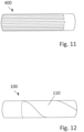
- the gel 124 may be heated above room temperature before injection into the mandrel 180.
- the mandrel 180 may be thermally conductive (for example, a metal mandrel), and some externally applied heat (for example, from the steam S) applied to thermoset the cellulose acetate. This may transfer heat energy to the gel, heating the gel may reduce its viscosity and facilitate its extrusion.
- the mandrel 180 is configured to reduce heating of the gel 124 prior to extrusion.
- the mandrel 180 is formed from a substantially thermally insulating material.
- the mandrel 180 is cooled, for example by having a liquid-cooled jacket 186 (for example a watercooled jacket), having a circulating layer of cooled liquid forming a thermal barrier between externally applied heat (for example steam S) and the gel 124. Maintaining the gel 124 at a cool temperature may facilitate shaping the gel 124 within the cellulose acetate 122 longitudinal sides of the gel element 500.
- the gel element 500 comprising gel 124 comprising an active agent is heated to a temperature of 375 degrees Celsius by the heating element 230 of the aerosol-generating device 200. At this temperature, material from the gel element 500 of the aerosol generating article 100 leaves the gel.
- negative pressure is applied to the proximal end 101 of the aerosol generating article 100, this material from the gel element 500 is drawn downstream through the aerosol-generating article 100, in particular drawn through the fluid guide 400 towards the proximal end and out of the proximal end 101 of the aerosol generating article 100.
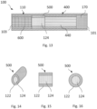
- the gel element 500 comprises cellulose acetate forming the longitudinal sides 122 of the cylindrical rod, with gel 124 in the core or central portion of the gel element 500.
- the longitudinal sides of the gel element 500 may be cardboard; crimped paper, such as crimped heat resistant paper or crimped parchment paper; or a polymeric material, for example low density polyethylene (LDPE).
- LDPE low density polyethylene
- the gel element 500 has a single core provided with a single gel 124, with the gel 124 filling the core, surrounded by cellulose acetate along the longitudinal sides of the gel element 500.
- the gel element 500 comprises more than one core.
- the gel element comprises more than one gel 124. Not all components of the gel element 500 of Figures 14, 15 and 16 are necessarily shown or labelled.
- the plurality of gels 524A, 524B may be extruded into the cellulose acetate 522 through separate conduits in the mandrel (not shown) forming the core of the gel element 500.
- the use of gels 124 with different volatilities may facilitate optimisation of delivery of the active agent.
- the gel element 500 comprises cellulose acetate longitudinal sides 622, the gel element 500 additionally comprises a plurality of cores 624A, 624B, 624C, as shown in cross-section in Figure 22 .
- Figure 28 illustrates an example where the gel element 500 comprises: a wrapper 110; a second gel element 115 comprising gel 124, the second gel element 115 comprises a paper wrapper, the second gel element is located centrally along the longitudinal axis of the gel element 500; porous medium loaded with gel 124 located between the second gel element 115 and the wrapper 110.
- the porous medium loaded with gel 124 helps to hold the second gel element 115 centrally within the gel element 500.
- Figure 30 illustrates an example where the gel element 500 comprises: a wrapper 110; a second gel element 115 comprising porous medium loaded with gel 125, the second gel element 115 comprises a paper wrapper; the second gel element 115 is located centrally along the longitudinal axis of the gel element 500; porous filler material 132 located between the second gel element 115 and the wrapper 110.
- the porous filler material 132 helps to hold the second gel element centrally within the gel element 500.
- the porous medium loaded with gel 125 in this example is located within the central portion of the second gel element 115.
- the paper wrapper of the second gel element 115 surrounds the porous medium loaded with gel.
- FIG 35 illustrates an example of an aerosol generating article 100 according to the present invention.
- This example is suitable for heating by induction and the Figure 35 shows heating elements 230 from an aerosol generating device (not shown).
- the heating elements 230 are external to the aerosol generating article but in the proximity of the gel element 500.
- the end plug 600 is of high resistance to draw (RTD) and comprises highly dense cellulose acetate.
- the end plug 600 is substantially non-porous.
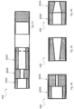
- Figure 37 illustrates another aerosol generating article 100 of the present invention, showing the three sections of the fluid guide 400A, 400B and 400C.
- Figures 38 to 44 show various fluid guide designs of the present invention. These designs can be used proximal to distal or distal to proximal depending on the desired flow required.
- the fluid guides can also be used in combination with any other fluid guide.
- Figure 43 and Figure 44 show more than one inner longitudinal passageway 430 that all have a constant cross-sectional area along the length of the fluid guide.
- Figure 43 has three inner longitudinal passageways 430 and
- Figure 44 has two inner longitudinal passageways 430.
Landscapes
- Physics & Mathematics (AREA)
- Electromagnetism (AREA)
- Chemical & Material Sciences (AREA)
- Chemical Kinetics & Catalysis (AREA)
- General Chemical & Material Sciences (AREA)
- Medicinal Preparation (AREA)
- Cigarettes, Filters, And Manufacturing Of Filters (AREA)
- Cosmetics (AREA)
Applications Claiming Priority (2)
| Application Number | Priority Date | Filing Date | Title |
|---|---|---|---|
| EP18212944 | 2018-12-17 | ||
| PCT/EP2019/085449 WO2020127118A1 (en) | 2018-12-17 | 2019-12-16 | Aerosol generating article for use with an aerosol generating device |
Publications (3)
| Publication Number | Publication Date |
|---|---|
| EP3897238A1 EP3897238A1 (en) | 2021-10-27 |
| EP3897238C0 EP3897238C0 (en) | 2025-04-09 |
| EP3897238B1 true EP3897238B1 (en) | 2025-04-09 |
Family
ID=64744378
Family Applications (1)
| Application Number | Title | Priority Date | Filing Date |
|---|---|---|---|
| EP19828257.6A Active EP3897238B1 (en) | 2018-12-17 | 2019-12-16 | Aerosol generating article for use with an aerosol generating device |
Country Status (6)
| Country | Link |
|---|---|
| US (1) | US11937645B2 (https=) |
| EP (1) | EP3897238B1 (https=) |
| JP (1) | JP7579251B2 (https=) |
| KR (1) | KR102906215B1 (https=) |
| CN (1) | CN113518561B (https=) |
| WO (1) | WO2020127118A1 (https=) |
Families Citing this family (10)
| Publication number | Priority date | Publication date | Assignee | Title |
|---|---|---|---|---|
| GB2561867B (en) * | 2017-04-25 | 2021-04-07 | Nerudia Ltd | Aerosol delivery system |
| GB202014600D0 (en) * | 2020-09-16 | 2020-10-28 | Nicoventures Holdings Ltd | Aerosol provision device |
| KR102573820B1 (ko) * | 2020-12-21 | 2023-08-31 | 주식회사 케이티앤지 | 에어로졸 생성 장치 |
| KR20240000514A (ko) * | 2021-04-23 | 2024-01-02 | 제이티 인터내셔널 소시에떼 아노님 | 에어로졸 발생 물품 그 제조 방법, 및 에어로졸 발생 시스템 |
| TW202241288A (zh) * | 2021-04-23 | 2022-11-01 | 瑞士商傑太日煙國際股份有限公司 | 氣溶膠產生製品 |
| US20240188627A1 (en) * | 2021-04-23 | 2024-06-13 | Jt International Sa | An Aerosol Generating Article and Method of Manufacturing the Same |
| BR112023026657A2 (pt) * | 2021-06-18 | 2024-03-05 | Nicoventures Trading Ltd | Artigo para uso em um sistema de fornecimento de aerossol não combustível, sistema e método de fabricação de um artigo |
| KR102542026B1 (ko) * | 2021-06-23 | 2023-06-12 | 주식회사 케이티앤지 | 에어로졸 생성 장치 |
| KR20230101132A (ko) * | 2021-12-29 | 2023-07-06 | 주식회사 케이티앤지 | 매질 세그먼트, 에어로졸 생성 물품 및 이를 포함하는 시스템 |
| CN114431521A (zh) * | 2022-03-08 | 2022-05-06 | 东莞市本草香弹科技有限公司 | 一种自封堵的气溶胶生成制品及其加工方法 |
Citations (1)
| Publication number | Priority date | Publication date | Assignee | Title |
|---|---|---|---|---|
| WO2018041924A1 (en) * | 2016-09-01 | 2018-03-08 | Philip Morris Products S.A. | Susceptor assembly and aerosol-generating article comprising the same |
Family Cites Families (24)
| Publication number | Priority date | Publication date | Assignee | Title |
|---|---|---|---|---|
| US4981522A (en) * | 1988-07-22 | 1991-01-01 | Philip Morris Incorporated | Thermally releasable flavor source for smoking articles |
| US5105838A (en) | 1990-10-23 | 1992-04-21 | R.J. Reynolds Tobacco Company | Cigarette |
| US5240016A (en) * | 1991-04-19 | 1993-08-31 | Philip Morris Incorporated | Thermally releasable gel-based flavor source for smoking articles |
| US5469871A (en) | 1992-09-17 | 1995-11-28 | R. J. Reynolds Tobacco Company | Cigarette and method of making same |
| US7302955B2 (en) * | 2003-05-06 | 2007-12-04 | Gary Pallino | Selectively tobacco shortened cigarette and method of use |
| US20070215167A1 (en) * | 2006-03-16 | 2007-09-20 | Evon Llewellyn Crooks | Smoking article |
| US9220301B2 (en) * | 2006-03-16 | 2015-12-29 | R.J. Reynolds Tobacco Company | Smoking article |
| US7726320B2 (en) * | 2006-10-18 | 2010-06-01 | R. J. Reynolds Tobacco Company | Tobacco-containing smoking article |
| US20110083687A1 (en) | 2009-10-09 | 2011-04-14 | Philip Morris Usa Inc. | Cigarette filter to reduce smoke deliveries in later puffs |
| EP2319334A1 (en) | 2009-10-27 | 2011-05-11 | Philip Morris Products S.A. | A smoking system having a liquid storage portion |
| JP2011205917A (ja) | 2010-03-29 | 2011-10-20 | British American Tobacco Japan Kk | 換気レベルを変えられる喫煙品 |
| RU2600911C2 (ru) | 2011-09-09 | 2016-10-27 | Филип Моррис Продактс С.А. | Фильтр курительного изделия с ограничивающим элементом и полостью |
| HUE034732T2 (en) * | 2012-04-30 | 2018-02-28 | Philip Morris Products Sa | Two-part multi-component interface |
| ITBO20130129A1 (it) | 2013-03-27 | 2014-09-28 | Gd Spa | Articolo da fumo |
| UA118457C2 (uk) | 2013-12-05 | 2019-01-25 | Філіп Морріс Продактс С.А. | Нагрівний виріб, що генерує аерозоль, з перегородкою для повітряного потоку |
| PT2996504T (pt) | 2014-05-21 | 2017-01-02 | Philip Morris Products Sa | Artigo gerador de aerossol tendo um susceptor de multimaterial |
| GB201511358D0 (en) | 2015-06-29 | 2015-08-12 | Nicoventures Holdings Ltd | Electronic aerosol provision systems |
| RU2706810C2 (ru) | 2015-09-11 | 2019-11-21 | Филип Моррис Продактс С.А. | Многокомпонентный элемент для изделия, генерирующего аэрозоль |
| MX2018007730A (es) | 2015-12-31 | 2018-08-15 | Philip Morris Products Sa | Articulo generador de aerosol quebradizo. |
| KR102525780B1 (ko) | 2016-05-25 | 2023-04-27 | 필립모리스 프로덕츠 에스.에이. | 피스톤을 포함하는 에어로졸 발생 물품 및 에어로졸 발생 장치 |
| HUE060625T2 (hu) | 2016-07-29 | 2023-03-28 | Philip Morris Products Sa | Gélt tartalmazó patront magában foglaló aeroszolfejlesztõ rendszer, valamint eszköz a patron melegítésére |
| CN206808668U (zh) | 2017-03-31 | 2017-12-29 | 深圳市合元科技有限公司 | 可调节进气量的雾化器和电子烟 |
| US11477861B2 (en) | 2017-05-10 | 2022-10-18 | Philip Morris Products S.A. | Aerosol-generating article, device and system for use with a plurality of aerosol-forming substrates |
| JP7590966B2 (ja) * | 2018-12-17 | 2024-11-27 | フィリップ・モーリス・プロダクツ・ソシエテ・アノニム | 熱源を含むエアロゾル発生物品 |
-
2019
- 2019-12-16 CN CN201980081147.9A patent/CN113518561B/zh active Active
- 2019-12-16 JP JP2021531963A patent/JP7579251B2/ja active Active
- 2019-12-16 US US17/413,713 patent/US11937645B2/en active Active
- 2019-12-16 EP EP19828257.6A patent/EP3897238B1/en active Active
- 2019-12-16 KR KR1020217017189A patent/KR102906215B1/ko active Active
- 2019-12-16 WO PCT/EP2019/085449 patent/WO2020127118A1/en not_active Ceased
Patent Citations (1)
| Publication number | Priority date | Publication date | Assignee | Title |
|---|---|---|---|---|
| WO2018041924A1 (en) * | 2016-09-01 | 2018-03-08 | Philip Morris Products S.A. | Susceptor assembly and aerosol-generating article comprising the same |
Also Published As
| Publication number | Publication date |
|---|---|
| WO2020127118A1 (en) | 2020-06-25 |
| KR20210101222A (ko) | 2021-08-18 |
| CN113518561B (zh) | 2024-01-02 |
| KR102906215B1 (ko) | 2026-01-02 |
| CN113518561A (zh) | 2021-10-19 |
| JP2022511513A (ja) | 2022-01-31 |
| US20220022543A1 (en) | 2022-01-27 |
| BR112021010478A2 (pt) | 2021-08-24 |
| US11937645B2 (en) | 2024-03-26 |
| EP3897238C0 (en) | 2025-04-09 |
| JP7579251B2 (ja) | 2024-11-07 |
| EP3897238A1 (en) | 2021-10-27 |
Similar Documents
| Publication | Publication Date | Title |
|---|---|---|
| US12402649B2 (en) | Tubular element, comprising porous medium, for use with an aerosol generating article | |
| US12329193B2 (en) | Tubular element, comprising porous medium and a wrapper, for use with an aerosol generating article | |
| EP3852555B1 (en) | Aerosol generating article comprising a heat source | |
| US12439956B2 (en) | Tubular element with threads for use with an aerosol generating article | |
| EP3897238B1 (en) | Aerosol generating article for use with an aerosol generating device | |
| US12144369B2 (en) | Tubular element for use with an aerosol generating article | |
| US20240358061A1 (en) | System, apparatus and method of manufacturing a tubular element for use with an aerosol generating article | |
| RU2796529C2 (ru) | Трубчатый элемент, содержащий пористую среду и обертку, для использования с изделием, генерирующим аэрозоль | |
| RU2811971C2 (ru) | Изделие, генерирующее аэрозоль, способ его изготовления и устройство, генерирующее аэрозоль, содержащее такое изделие | |
| RU2796278C9 (ru) | Трубчатый элемент для использования с изделием для генерирования аэрозоля | |
| RU2796278C2 (ru) | Трубчатый элемент для использования с изделием для генерирования аэрозоля | |
| RU2802205C2 (ru) | Изделие, генерирующее аэрозоль, содержащее источник тепла, и способ изготовления такого изделия |
Legal Events
| Date | Code | Title | Description |
|---|---|---|---|
| STAA | Information on the status of an ep patent application or granted ep patent |
Free format text: STATUS: UNKNOWN |
|
| STAA | Information on the status of an ep patent application or granted ep patent |
Free format text: STATUS: THE INTERNATIONAL PUBLICATION HAS BEEN MADE |
|
| PUAI | Public reference made under article 153(3) epc to a published international application that has entered the european phase |
Free format text: ORIGINAL CODE: 0009012 |
|
| STAA | Information on the status of an ep patent application or granted ep patent |
Free format text: STATUS: REQUEST FOR EXAMINATION WAS MADE |
|
| 17P | Request for examination filed |
Effective date: 20210507 |
|
| AK | Designated contracting states |
Kind code of ref document: A1 Designated state(s): AL AT BE BG CH CY CZ DE DK EE ES FI FR GB GR HR HU IE IS IT LI LT LU LV MC MK MT NL NO PL PT RO RS SE SI SK SM TR |
|
| DAV | Request for validation of the european patent (deleted) | ||
| DAX | Request for extension of the european patent (deleted) | ||
| GRAJ | Information related to disapproval of communication of intention to grant by the applicant or resumption of examination proceedings by the epo deleted |
Free format text: ORIGINAL CODE: EPIDOSDIGR1 |
|
| GRAP | Despatch of communication of intention to grant a patent |
Free format text: ORIGINAL CODE: EPIDOSNIGR1 |
|
| GRAP | Despatch of communication of intention to grant a patent |
Free format text: ORIGINAL CODE: EPIDOSNIGR1 |
|
| STAA | Information on the status of an ep patent application or granted ep patent |
Free format text: STATUS: GRANT OF PATENT IS INTENDED |
|
| INTG | Intention to grant announced |
Effective date: 20241105 |
|
| GRAS | Grant fee paid |
Free format text: ORIGINAL CODE: EPIDOSNIGR3 |
|
| GRAA | (expected) grant |
Free format text: ORIGINAL CODE: 0009210 |
|
| STAA | Information on the status of an ep patent application or granted ep patent |
Free format text: STATUS: THE PATENT HAS BEEN GRANTED |
|
| AK | Designated contracting states |
Kind code of ref document: B1 Designated state(s): AL AT BE BG CH CY CZ DE DK EE ES FI FR GB GR HR HU IE IS IT LI LT LU LV MC MK MT NL NO PL PT RO RS SE SI SK SM TR |
|
| REG | Reference to a national code |
Ref country code: GB Ref legal event code: FG4D |
|
| REG | Reference to a national code |
Ref country code: CH Ref legal event code: EP |
|
| REG | Reference to a national code |
Ref country code: IE Ref legal event code: FG4D |
|
| U01 | Request for unitary effect filed |
Effective date: 20250409 |
|
| U07 | Unitary effect registered |
Designated state(s): AT BE BG DE DK EE FI FR IT LT LU LV MT NL PT RO SE SI Effective date: 20250415 |
|
| PG25 | Lapsed in a contracting state [announced via postgrant information from national office to epo] |
Ref country code: ES Free format text: LAPSE BECAUSE OF FAILURE TO SUBMIT A TRANSLATION OF THE DESCRIPTION OR TO PAY THE FEE WITHIN THE PRESCRIBED TIME-LIMIT Effective date: 20250409 |
|
| PG25 | Lapsed in a contracting state [announced via postgrant information from national office to epo] |
Ref country code: GR Free format text: LAPSE BECAUSE OF FAILURE TO SUBMIT A TRANSLATION OF THE DESCRIPTION OR TO PAY THE FEE WITHIN THE PRESCRIBED TIME-LIMIT Effective date: 20250710 Ref country code: NO Free format text: LAPSE BECAUSE OF FAILURE TO SUBMIT A TRANSLATION OF THE DESCRIPTION OR TO PAY THE FEE WITHIN THE PRESCRIBED TIME-LIMIT Effective date: 20250709 |
|
| PG25 | Lapsed in a contracting state [announced via postgrant information from national office to epo] |
Ref country code: PL Free format text: LAPSE BECAUSE OF FAILURE TO SUBMIT A TRANSLATION OF THE DESCRIPTION OR TO PAY THE FEE WITHIN THE PRESCRIBED TIME-LIMIT Effective date: 20250409 |
|
| PG25 | Lapsed in a contracting state [announced via postgrant information from national office to epo] |
Ref country code: HR Free format text: LAPSE BECAUSE OF FAILURE TO SUBMIT A TRANSLATION OF THE DESCRIPTION OR TO PAY THE FEE WITHIN THE PRESCRIBED TIME-LIMIT Effective date: 20250409 |
|
| PG25 | Lapsed in a contracting state [announced via postgrant information from national office to epo] |
Ref country code: RS Free format text: LAPSE BECAUSE OF FAILURE TO SUBMIT A TRANSLATION OF THE DESCRIPTION OR TO PAY THE FEE WITHIN THE PRESCRIBED TIME-LIMIT Effective date: 20250709 |
|
| PG25 | Lapsed in a contracting state [announced via postgrant information from national office to epo] |
Ref country code: IS Free format text: LAPSE BECAUSE OF FAILURE TO SUBMIT A TRANSLATION OF THE DESCRIPTION OR TO PAY THE FEE WITHIN THE PRESCRIBED TIME-LIMIT Effective date: 20250809 |
|
| REG | Reference to a national code |
Ref country code: CH Ref legal event code: U11 Free format text: ST27 STATUS EVENT CODE: U-0-0-U10-U11 (AS PROVIDED BY THE NATIONAL OFFICE) Effective date: 20260101 |
|
| PGFP | Annual fee paid to national office [announced via postgrant information from national office to epo] |
Ref country code: GB Payment date: 20251219 Year of fee payment: 7 |
|
| PG25 | Lapsed in a contracting state [announced via postgrant information from national office to epo] |
Ref country code: SM Free format text: LAPSE BECAUSE OF FAILURE TO SUBMIT A TRANSLATION OF THE DESCRIPTION OR TO PAY THE FEE WITHIN THE PRESCRIBED TIME-LIMIT Effective date: 20250409 |
|
| PG25 | Lapsed in a contracting state [announced via postgrant information from national office to epo] |
Ref country code: CZ Free format text: LAPSE BECAUSE OF FAILURE TO SUBMIT A TRANSLATION OF THE DESCRIPTION OR TO PAY THE FEE WITHIN THE PRESCRIBED TIME-LIMIT Effective date: 20250409 |
|
| PG25 | Lapsed in a contracting state [announced via postgrant information from national office to epo] |
Ref country code: SK Free format text: LAPSE BECAUSE OF FAILURE TO SUBMIT A TRANSLATION OF THE DESCRIPTION OR TO PAY THE FEE WITHIN THE PRESCRIBED TIME-LIMIT Effective date: 20250409 |
|
| U20 | Renewal fee for the european patent with unitary effect paid |
Year of fee payment: 7 Effective date: 20251230 |
|
| PLBE | No opposition filed within time limit |
Free format text: ORIGINAL CODE: 0009261 |
|
| STAA | Information on the status of an ep patent application or granted ep patent |
Free format text: STATUS: NO OPPOSITION FILED WITHIN TIME LIMIT |
|
| REG | Reference to a national code |
Ref country code: CH Ref legal event code: L10 Free format text: ST27 STATUS EVENT CODE: U-0-0-L10-L00 (AS PROVIDED BY THE NATIONAL OFFICE) Effective date: 20260218 |
|
| 26N | No opposition filed |
Effective date: 20260112 |
|
| PGFP | Annual fee paid to national office [announced via postgrant information from national office to epo] |
Ref country code: CH Payment date: 20260101 Year of fee payment: 7 |