EP3897073B1 - Vaporizer - Google Patents
Vaporizer Download PDFInfo
- Publication number
- EP3897073B1 EP3897073B1 EP21178682.7A EP21178682A EP3897073B1 EP 3897073 B1 EP3897073 B1 EP 3897073B1 EP 21178682 A EP21178682 A EP 21178682A EP 3897073 B1 EP3897073 B1 EP 3897073B1
- Authority
- EP
- European Patent Office
- Prior art keywords
- cartomizer
- battery
- vaporizer
- proximate
- segment
- Prior art date
- Legal status (The legal status is an assumption and is not a legal conclusion. Google has not performed a legal analysis and makes no representation as to the accuracy of the status listed.)
- Active
Links
- 239000006200 vaporizer Substances 0.000 title claims description 41
- 239000012530 fluid Substances 0.000 claims description 39
- 238000010438 heat treatment Methods 0.000 claims description 37
- 230000008878 coupling Effects 0.000 claims description 12
- 238000010168 coupling process Methods 0.000 claims description 12
- 238000005859 coupling reaction Methods 0.000 claims description 12
- 238000004891 communication Methods 0.000 claims description 3
- 238000007789 sealing Methods 0.000 claims description 2
- 239000002775 capsule Substances 0.000 description 12
- 230000001939 inductive effect Effects 0.000 description 9
- 230000008016 vaporization Effects 0.000 description 8
- 239000007788 liquid Substances 0.000 description 7
- DNIAPMSPPWPWGF-UHFFFAOYSA-N Propylene glycol Chemical compound CC(O)CO DNIAPMSPPWPWGF-UHFFFAOYSA-N 0.000 description 6
- 239000003571 electronic cigarette Substances 0.000 description 6
- SNICXCGAKADSCV-JTQLQIEISA-N (-)-Nicotine Chemical compound CN1CCC[C@H]1C1=CC=CN=C1 SNICXCGAKADSCV-JTQLQIEISA-N 0.000 description 5
- 238000000034 method Methods 0.000 description 5
- 229960002715 nicotine Drugs 0.000 description 5
- SNICXCGAKADSCV-UHFFFAOYSA-N nicotine Natural products CN1CCCC1C1=CC=CN=C1 SNICXCGAKADSCV-UHFFFAOYSA-N 0.000 description 5
- 238000009834 vaporization Methods 0.000 description 5
- RPPNJBZNXQNKNM-UHFFFAOYSA-N 1,2,4-trichloro-3-(2,4,6-trichlorophenyl)benzene Chemical compound ClC1=CC(Cl)=CC(Cl)=C1C1=C(Cl)C=CC(Cl)=C1Cl RPPNJBZNXQNKNM-UHFFFAOYSA-N 0.000 description 3
- 239000000796 flavoring agent Substances 0.000 description 3
- 235000019634 flavors Nutrition 0.000 description 3
- PEDCQBHIVMGVHV-UHFFFAOYSA-N Glycerine Chemical compound OCC(O)CO PEDCQBHIVMGVHV-UHFFFAOYSA-N 0.000 description 2
- 241000208125 Nicotiana Species 0.000 description 2
- 235000002637 Nicotiana tabacum Nutrition 0.000 description 2
- 238000003780 insertion Methods 0.000 description 2
- 230000037431 insertion Effects 0.000 description 2
- 239000002184 metal Substances 0.000 description 2
- 229940068918 polyethylene glycol 400 Drugs 0.000 description 2
- NOOLISFMXDJSKH-UTLUCORTSA-N (+)-Neomenthol Chemical compound CC(C)[C@@H]1CC[C@@H](C)C[C@@H]1O NOOLISFMXDJSKH-UTLUCORTSA-N 0.000 description 1
- NOOLISFMXDJSKH-UHFFFAOYSA-N DL-menthol Natural products CC(C)C1CCC(C)CC1O NOOLISFMXDJSKH-UHFFFAOYSA-N 0.000 description 1
- 229920002565 Polyethylene Glycol 400 Polymers 0.000 description 1
- 235000009499 Vanilla fragrans Nutrition 0.000 description 1
- 244000263375 Vanilla tahitensis Species 0.000 description 1
- 235000012036 Vanilla tahitensis Nutrition 0.000 description 1
- 230000004888 barrier function Effects 0.000 description 1
- 235000019504 cigarettes Nutrition 0.000 description 1
- 239000012141 concentrate Substances 0.000 description 1
- 230000001419 dependent effect Effects 0.000 description 1
- 238000013461 design Methods 0.000 description 1
- 235000013399 edible fruits Nutrition 0.000 description 1
- 238000005516 engineering process Methods 0.000 description 1
- 230000007613 environmental effect Effects 0.000 description 1
- 235000011187 glycerol Nutrition 0.000 description 1
- 238000004519 manufacturing process Methods 0.000 description 1
- 239000000463 material Substances 0.000 description 1
- 229940041616 menthol Drugs 0.000 description 1
- 238000012986 modification Methods 0.000 description 1
- 230000004048 modification Effects 0.000 description 1
- 230000008569 process Effects 0.000 description 1
- 239000000126 substance Substances 0.000 description 1
- 230000007704 transition Effects 0.000 description 1
- 235000013311 vegetables Nutrition 0.000 description 1
Images


Classifications
-
- H—ELECTRICITY
- H05—ELECTRIC TECHNIQUES NOT OTHERWISE PROVIDED FOR
- H05B—ELECTRIC HEATING; ELECTRIC LIGHT SOURCES NOT OTHERWISE PROVIDED FOR; CIRCUIT ARRANGEMENTS FOR ELECTRIC LIGHT SOURCES, IN GENERAL
- H05B3/00—Ohmic-resistance heating
- H05B3/40—Heating elements having the shape of rods or tubes
- H05B3/42—Heating elements having the shape of rods or tubes non-flexible
- H05B3/46—Heating elements having the shape of rods or tubes non-flexible heating conductor mounted on insulating base
-
- A—HUMAN NECESSITIES
- A24—TOBACCO; CIGARS; CIGARETTES; SIMULATED SMOKING DEVICES; SMOKERS' REQUISITES
- A24F—SMOKERS' REQUISITES; MATCH BOXES; SIMULATED SMOKING DEVICES
- A24F40/00—Electrically operated smoking devices; Component parts thereof; Manufacture thereof; Maintenance or testing thereof; Charging means specially adapted therefor
- A24F40/40—Constructional details, e.g. connection of cartridges and battery parts
- A24F40/42—Cartridges or containers for inhalable precursors
-
- A—HUMAN NECESSITIES
- A24—TOBACCO; CIGARS; CIGARETTES; SIMULATED SMOKING DEVICES; SMOKERS' REQUISITES
- A24F—SMOKERS' REQUISITES; MATCH BOXES; SIMULATED SMOKING DEVICES
- A24F40/00—Electrically operated smoking devices; Component parts thereof; Manufacture thereof; Maintenance or testing thereof; Charging means specially adapted therefor
- A24F40/40—Constructional details, e.g. connection of cartridges and battery parts
- A24F40/48—Fluid transfer means, e.g. pumps
- A24F40/485—Valves; Apertures
-
- A—HUMAN NECESSITIES
- A61—MEDICAL OR VETERINARY SCIENCE; HYGIENE
- A61M—DEVICES FOR INTRODUCING MEDIA INTO, OR ONTO, THE BODY; DEVICES FOR TRANSDUCING BODY MEDIA OR FOR TAKING MEDIA FROM THE BODY; DEVICES FOR PRODUCING OR ENDING SLEEP OR STUPOR
- A61M11/00—Sprayers or atomisers specially adapted for therapeutic purposes
- A61M11/04—Sprayers or atomisers specially adapted for therapeutic purposes operated by the vapour pressure of the liquid to be sprayed or atomised
- A61M11/041—Sprayers or atomisers specially adapted for therapeutic purposes operated by the vapour pressure of the liquid to be sprayed or atomised using heaters
- A61M11/042—Sprayers or atomisers specially adapted for therapeutic purposes operated by the vapour pressure of the liquid to be sprayed or atomised using heaters electrical
-
- A—HUMAN NECESSITIES
- A61—MEDICAL OR VETERINARY SCIENCE; HYGIENE
- A61M—DEVICES FOR INTRODUCING MEDIA INTO, OR ONTO, THE BODY; DEVICES FOR TRANSDUCING BODY MEDIA OR FOR TAKING MEDIA FROM THE BODY; DEVICES FOR PRODUCING OR ENDING SLEEP OR STUPOR
- A61M15/00—Inhalators
- A61M15/06—Inhaling appliances shaped like cigars, cigarettes or pipes
-
- F—MECHANICAL ENGINEERING; LIGHTING; HEATING; WEAPONS; BLASTING
- F22—STEAM GENERATION
- F22B—METHODS OF STEAM GENERATION; STEAM BOILERS
- F22B1/00—Methods of steam generation characterised by form of heating method
- F22B1/28—Methods of steam generation characterised by form of heating method in boilers heated electrically
- F22B1/284—Methods of steam generation characterised by form of heating method in boilers heated electrically with water in reservoirs
-
- A—HUMAN NECESSITIES
- A24—TOBACCO; CIGARS; CIGARETTES; SIMULATED SMOKING DEVICES; SMOKERS' REQUISITES
- A24F—SMOKERS' REQUISITES; MATCH BOXES; SIMULATED SMOKING DEVICES
- A24F40/00—Electrically operated smoking devices; Component parts thereof; Manufacture thereof; Maintenance or testing thereof; Charging means specially adapted therefor
- A24F40/10—Devices using liquid inhalable precursors
-
- A—HUMAN NECESSITIES
- A24—TOBACCO; CIGARS; CIGARETTES; SIMULATED SMOKING DEVICES; SMOKERS' REQUISITES
- A24F—SMOKERS' REQUISITES; MATCH BOXES; SIMULATED SMOKING DEVICES
- A24F40/00—Electrically operated smoking devices; Component parts thereof; Manufacture thereof; Maintenance or testing thereof; Charging means specially adapted therefor
- A24F40/90—Arrangements or methods specially adapted for charging batteries thereof
-
- A—HUMAN NECESSITIES
- A61—MEDICAL OR VETERINARY SCIENCE; HYGIENE
- A61M—DEVICES FOR INTRODUCING MEDIA INTO, OR ONTO, THE BODY; DEVICES FOR TRANSDUCING BODY MEDIA OR FOR TAKING MEDIA FROM THE BODY; DEVICES FOR PRODUCING OR ENDING SLEEP OR STUPOR
- A61M2205/00—General characteristics of the apparatus
- A61M2205/36—General characteristics of the apparatus related to heating or cooling
- A61M2205/3653—General characteristics of the apparatus related to heating or cooling by Joule effect, i.e. electric resistance
-
- A—HUMAN NECESSITIES
- A61—MEDICAL OR VETERINARY SCIENCE; HYGIENE
- A61M—DEVICES FOR INTRODUCING MEDIA INTO, OR ONTO, THE BODY; DEVICES FOR TRANSDUCING BODY MEDIA OR FOR TAKING MEDIA FROM THE BODY; DEVICES FOR PRODUCING OR ENDING SLEEP OR STUPOR
- A61M2205/00—General characteristics of the apparatus
- A61M2205/82—Internal energy supply devices
- A61M2205/8206—Internal energy supply devices battery-operated
Definitions
- This disclosure relates generally to vaporizers, which may also be referred to as electronic cigarettes.
- Vaporizers have recently emerged as a new product for providing nicotine through a smokeless inhalation process.
- the electronic cigarette There are many embodiments of the electronic cigarette.
- Most implementations consist of a power supply (typically a battery) and an atomizing device.
- a power supply typically a battery
- an atomizing device In reusable electronic cigarettes the two items are separated into a battery and a cartomizer, to allow the disposal and replacement of the nicotine containing fluid cartomizer while preserving the more costly battery and associated circuitry (microcontroller, switch, indicating LED, etc.)
- the two items are combined to integrate the functions into one unit that is disposed of after either the battery energy or the nicotine containing liquid is exhausted.
- the liquid that is used to produce vapor in electronic cigarettes is generally a solution of one or more of propylene glycol (PG) and/or vegetable glycerin (VG) and/or polyethylene glycol 400 (PEG400) mixed with concentrated flavors, and optionally, a variable percentage of a liquid nicotine concentrate.
- PG propylene glycol
- VG vegetable glycerin
- PEG400 polyethylene glycol 400
- concentrated flavors and optionally, a variable percentage of a liquid nicotine concentrate.
- the solution is often sold in a bottle or in disposable cartridges or cartomizers. Many different flavors of such liquid are sold, including flavors that resemble the taste of regular tobacco, menthol, vanilla, coffee, cola and various fruits.
- Various nicotine concentrations are also available, and nicotine-free solutions are also common.
- CN 202 566 289 U discloses an electronic cigarette, in which a tobacco cigarette can be inserted.
- US 2013/0298905 A1 discloses a vaporizer for vaporizing a substance, wherein the vaporizer comprises a power source, a heating portion, an inhalation sensor, a temperature sensor, a distal light source and a grinding portion, which allows manual grinding of material into smaller pieces to facilitate vaporization.
- the invention is a vaporizer according to claim 1.
- the dependent claims represent preferred embodiments of the invention.
- a vaporizer may include a cartomizer and a battery segment.
- the cartomizer have may have a first cartomizer end and a second cartomizer end.
- the cartomizer may include an outer cartomizer shell, an internal cavity defined by a portion of the outer cartomizer shell, a heating chamber provided within the outer cartomizer shell and adjacent to the internal cavity, a heating element provided within the heating chamber, a fluid container conformingly dimensioned with the internal cavity, the fluid container insertable and removable from the internal cavity, a mouthpiece provided at or proximate to the second cartomizer end, an airflow channel in fluid communication with the heating chamber and the mouthpiece, cartomizer electrical contacts provided on the outer cartomizer shell proximate the first cartomizer end, and cartomizer electrical circuitry operable to direct an electric current between the cartomizer electrical contacts and the heating element.
- the battery segment may include an outer battery shell having a first battery end and a second battery end, the cartomizer connectable with the battery segment proximate the first cartomizer end and the first battery end, a battery housed within the outer battery shell, battery electrical contacts provided proximate the first battery end and positioned to contact the cartomizer electrical contacts when the cartomizer is connected to the battery segment, and battery electrical circuitry housed within the battery segment and operable to direct an electrical current between the battery, the battery electrical contacts, the cartomizer electrical contacts, and the heating element.
- a portion of the airflow channel is positioned between the outer cartomizer shell and the fluid container.
- the cartomizer may further include a piercing element proximate the heating chamber and dimensioned to puncture a base end of the fluid container when the fluid container is received in the internal cavity.
- a self-healing gasket may be provided at or proximate to the base end of the fluid container, the self-healing gasket thereby sealing the base end of the liquid container after the piercing element is removed.
- the piercing element may be a hollow needle capable of allowing the vaporizable fluid to travel from the fluid container to the heating chamber through the hollow needle.
- the cartomizer may further include an adjustable air valve provided to allow air to be drawn into the airflow channel.
- the vaporizer may further include at least one magnet connected to the battery segment proximate the first end of the battery segment, the at least one magnet operable to secure the cartomizer to the battery segment.
- the vaporizer may further include at least one magnet connected to the cartomizer proximate the first cartomizer end capable of securing the battery segment to the cartomizer.
- the battery segment may include at least one charging port capable of charging the battery.
- the at least one charging port may be arranged on the first end of the battery segment.
- the at least one charging port may include connectors for coupling to complimentary connectors of a charger.
- the vaporizer may further include a printed circuit board housed in the battery segment and electrically connected to the battery electrical circuitry.
- the vaporizer may further include at least one illuminable indicator electrically connected to the printed circuit board.
- the battery segment may be dimensioned to receive the cartomizer proximate the first battery end.
- the battery segment and the cartomizer may have substantially cylindrical cross-sections.
- an embodiment of a vaporizer 10 may include a battery segment 100, having a cartomizer-side or first end 102 and a charger-side or second end 104, in addition to a cartomizer 200, having a battery-side or first end 202 and a mouthpiece-side or second end 204.
- Cartomizer 200 may be operable to hold a vaporizable fluid 300.
- Battery segment 100 may be connectable with the cartomizer 200 through, for example, insertion of the battery-side end 202 of the cartomizer segment into a chamber proximate to the cartomizer-side end 102 of the battery segment 100.
- battery segment 100 is illustrated as a substantially elongate member, other dimensions and shapes are contemplated within the disclosure.
- the battery segment 100 and the cartomizer 200 may be conformingly shaped into a substantially cylindrical or tubular cross-section, with the cartomizer dimensioned to secured on or within a chamber of battery segment 100 proximate to the battery-side end 102. This conformed fit between battery segment 100 and cartomizer 200 may operate to ensure proper fitting and coupling of cartomizer 200 into a chamber of battery segment 100.
- Other cross-section shapes including for instance a substantially circular cross section for either battery segment 100 or cartomizer 200, are also contemplated within the disclosure. It is further contemplated that either battery segment 100 or cartomizer 200 may be re-dimensioned so that they are not substantially elongate, as shown in the illustrated embodiments.
- Battery segment 100 may include an outer shell 110 for protecting the various components housed internally within at least a portion of shell 110.
- One component which may be housed within shell 110 is a battery 120, which in some embodiments is rechargeable.
- a charging port 130 may be provided.
- charging port 130 is provided proximate to charger-side 104.
- Charging port may be charged either through direct contact with an electrical source or, alternatively, through inductive charging.
- charging port 130 may have connectors, such as threadings or magnets, for directly coupling a charger with charging port 130.
- a charger may have male threadings connectable with female threadings provided as part of charging port 130, or charging port 130 may have magnets for securing a charger having magnets of opposing polarities.
- One such charger with magnet couplings is disclosed in U.S. Application No. 14/201,267 .
- a removable cap could be provided to cover either magnets or threadings so that they are not exposed when not coupled with a charger.
- the charger may then be connected to a power source, such as through a USB cable or a standard electrical outlet.
- charging port 130 may include inductive wireless technology which allows the battery 120 to be charged by placing charging port 130 proximate to an inductive charging pad used for wireless charging.
- charging port 130 is dual-functioning in that battery 120 may be charged by either coupling a charger to charging port 130 or placing battery segment 100 near an inductive charging pad, for instance setting battery segment 100 on top of an inductive charging pad.
- Battery segment 100 may include more than one charging port 130, where for instance a first charging port and a second charging port are concurrently provided.
- the first charging port may have the ability to charge battery 120 through a first charging method while the second charging port may have the ability to charge battery 120 through a second charging method.
- Either the first or second charging method may be direct charging facilitated by directly coupling the charging port with a charger, and the other charging method may be indirect or inductive charging facilitated by placing the associated charging port proximate to an inductive charging pad.
- a first charging port may be provided proximate to charger-side 104 and may be operable to inductively charge battery 120
- a second charging port may be provided proximate to battery-side 102 and may be operable to directly couple with a charger, which may be receivable within the same chamber which cartomizer 200 is insertable into.
- various embodiments of vaporizer 10 contemplate battery 120 being rechargeable either through direct coupling of a charger to charging port 130, through inductive charging from placing an inductive charging source proximate to charging port 130.
- One or more magnets 140 may be provided in order to secure or couple battery segment 100 with cartomizer 200 as cartomizer 200 is positioned proximate to magnets 140. Magnets 140 may secure the cartomizer 200 through a magnetic attraction with either magnets 240 included with cartomizer 200 or with metal pieces or strips in lieu of active magnets 240. Alternatively, magnets 240 may be provided proximate to battery side 202 of cartomizer 200, and magnets 240 may engage one or more metal strips or pieces 140 in order to establish a magnetic coupling between cartomizer 200 and battery segment 100.
- Other connectors are contemplated within the disclosure in order to couple battery segment 100 and cartomizer 200 including, for instance, threaded connectors or any other known or to be discovered connector. A snap-fit or friction-fit connection between cartomizer 200 and battery segment 100 is also contemplated within the disclosure.
- the electronic control system may be provided in order to operate various functions of vaporizer 10.
- the electronic control system may include a printed circuit board (PCB) 150, which in one embodiment may be substantially elongate and run through at least a portion of the elongate shell 110.
- PCB 150 In connection with PCB 150 may be one or more indicators 152 as well as one or more control buttons or switches 154.
- a series of indicators 152 such as the sequentially aligned five (5) indicators shown in the illustrated embodiment of FIG. 1 and FIG. 3 , may be operable to indicate a charging or power status of battery segment 100.
- the indicators may be illuminable, for instance through one or more light emitting diodes (LEDs) included in each indicator 152.
- LEDs light emitting diodes
- each indicator 152 may be composed of one of a series of sequentially drilled holes in a portion of shell 110, with an LED positioned behind the sequentially drilled holes.
- Buttons 154 may be capacitive touch buttons, manipulable upon pressure or simple contact by a user, or alternatively may be any known or to be developed buttons operable to control the various functions of vaporizer 10 through the electronic control system.
- a PCB connection 156 may also be provided as part of the electronic control system. Connection 156 may operate to transmit electrical signals to a coupled cartomizer 200 so that electronically controlled functions of cartomizer 200 may be operated through battery segment 100, including through manipulation of buttons 154. Connection 156 may be provided at the base of the chamber proximate to cartomizer-side 102 of battery segment 100.
- An air switch controller 160 may also be provided and controlled by and through PCB 150.
- Cartomizer 200 may include an outer shell 210, the interior of which may include a fluid chamber 212 for holding vaporizable fluid 300.
- a mouthpiece 220 may be provided on cartomizer 200 at or proximate to mouthpiece-end 204.
- mouthpiece 220 is releasably attachable to cartomizer 200 in order to expose fluid chamber 212 so that user may add additional fluid 300.
- mouthpiece 220 may be attached to cartomizer shell 210 by any known or to be developed connector, including threadings or push-in friction fitting.
- Cartomizer 200 may be divided into a fluid chamber 212 and a heating chamber 214, with the chambers separated by a wall or other barrier.
- the heating chamber 214 may be provided proximate to battery-side end 202, while fluid chamber 212 may be provided proximate to mouthpiece-side end 204.
- a heating or vaporizing unit 230 may be provided within heating chamber 214, where the vaporizing unit is operable to receive fluid 300 from fluid chamber 212 and to heat fluid 300 to a vaporization temperature. Once a vaporization temperature is obtained, fluid 300 transitions to a vapor and may pass through an airflow channel 216 to mouthpiece 220.
- Airflow channel 216 in one embodiment may be a passageway running between fluid chamber 212 and outer shell 210.
- airflow channel 216 may be a composed of a tube or other similar structure extending between heating chamber 214 and mouthpiece 220, through fluid chamber 212.
- An cartomizer electronic control system may also be provided as part of cartomizer 200, where the cartomizer electronic control system may include a Cartomizer PCB 150.
- Magnets 240 may also be provided within heating chamber 214.
- FIGS. 3 and 4 illustrate additional embodiments of a vaporizer in accordance with the disclosure.
- FIG. 5 illustrates an exploded view of a deconstructed vaporizer, in accordance with the disclosure.
- FIG. 6 illustrates an embodiment of cartomizer 200 which may be connected with embodiments of battery segment 100 as part of embodiments of vaporizer 10, in accordance with the disclosure.
- Cartomizer 200 may include an outer shell 210 having a first end 202 and a mouthpiece end 204. The interior of shell 210 may be dimensioned to receive a removable fluid chamber or capsule 212 having capsule walls 212a.
- a removable mouthpiece 220 may be provided on cartomizer 200 at or proximate to mouthpiece-end 204.
- a heater housing 214 Proximate to first end 202, a heater housing 214 may be provided for holding a heating element 230, which in one embodiment may be a heating coil whose temperature may be elevated to a vaporization temperature upon passing a current through the wound coil.
- a coupling component 242 may be provided to facilitate connection with battery segment 100 as well as for securing heater housing 214.
- Capsule 212 may further include a capsule base 222 and a self-healing rubber gasket 224. As capsule 212 is inserted, an end portion of capsule 212 may be pierced by a puncturing needle 232. In some embodiments, such as the illustrated embodiment, needle 232 may puncture a center area of gasket 224, while in other embodiments needle 232 may puncture a bottom portion of capsule wall 212a or, alternatively, the capsule base 222. In embodiments where needle 232 punctures self-healing rubber gasket 224, the self-healing nature of gasket 224 may allow removal of capsule 212 without leaking, thereby permitting multiple insertion and removals without unintended leaking. Once punctured, vaporizable liquid may travel from capsule 212 through needle 232 to heating element 230 where it may be vaporized to a vaporization temperature and converted from a liquid to an inhalable gas.
- An air side channel 216 may be provided for fluidly connecting mouthpiece 220 and heating element 230.
- air channel 216 extends longitudinally along a portion of the length of outer shell 210 substantially parallel to an inserted cartridge 212.
- Environmental air from immediately outside vaporizer 10 may be drawn into an airflow channel through opening 218, which may be an adjustable air valve.
- opening 218, may be an adjustable air valve.
- users of vaporizer 10 may regulate air flow as may be desirable.
- a greater or full open opening 218 may produce significantly larger clouds of vapor, while a smaller or partially closed opening 218 may produce smaller but more concentrated vapor.
- the air channel may continue to be defined along an internal area of cartomizer 200 proximate to first end 202, which for instance may be a portion of coupling component 242, upwards towards heating element 230, and through a gap 226 leading to air side channel 216 and terminating at mouthpiece 220.
- a PCB 250 may be further provided in order to control various components of cartomizer 200, for instance current control to heating element 230 or operation of valve 218.
- An electrical current may be provided from battery in battery segment 100 to cartomizer 200 through electrical contacts provided proximate to first end 202.
Description
- This application claims priority to
U.S. Provisional Application No. 61/987,196 filed on May 1, 2014 U.S. Provisional Application No. 62/038,785 filed on August 18, 2014 U.S. Design Patent Application No. 29/498,556 filed on August 05, 2014 - This disclosure relates generally to vaporizers, which may also be referred to as electronic cigarettes.
- Vaporizers have recently emerged as a new product for providing nicotine through a smokeless inhalation process. There are many embodiments of the electronic cigarette. Most implementations consist of a power supply (typically a battery) and an atomizing device. In reusable electronic cigarettes the two items are separated into a battery and a cartomizer, to allow the disposal and replacement of the nicotine containing fluid cartomizer while preserving the more costly battery and associated circuitry (microcontroller, switch, indicating LED, etc.) In disposable electronic cigarettes the two items are combined to integrate the functions into one unit that is disposed of after either the battery energy or the nicotine containing liquid is exhausted.
- The liquid that is used to produce vapor in electronic cigarettes is generally a solution of one or more of propylene glycol (PG) and/or vegetable glycerin (VG) and/or polyethylene glycol 400 (PEG400) mixed with concentrated flavors, and optionally, a variable percentage of a liquid nicotine concentrate. The solution is often sold in a bottle or in disposable cartridges or cartomizers. Many different flavors of such liquid are sold, including flavors that resemble the taste of regular tobacco, menthol, vanilla, coffee, cola and various fruits. Various nicotine concentrations are also available, and nicotine-free solutions are also common.
-
CN 202 566 289 U -
US 2013/0298905 A1 discloses a vaporizer for vaporizing a substance, wherein the vaporizer comprises a power source, a heating portion, an inhalation sensor, a
temperature sensor, a distal light source and a grinding portion, which allows manual grinding of material into smaller pieces to facilitate vaporization. - The invention is a vaporizer according to claim 1. The dependent claims represent preferred embodiments of the invention.
- The following examples of the disclosure do not form part of the invention, but represent useful aspects for understanding the invention.
- In one example of the disclosure, a vaporizer may include a cartomizer and a battery segment. The cartomizer have may have a first cartomizer end and a second cartomizer end. The cartomizer may include an outer cartomizer shell, an internal cavity defined by a portion of the outer cartomizer shell, a heating chamber provided within the outer cartomizer shell and adjacent to the internal cavity, a heating element provided within the heating chamber, a fluid container conformingly dimensioned with the internal cavity, the fluid container insertable and removable from the internal cavity, a mouthpiece provided at or proximate to the second cartomizer end, an airflow channel in fluid communication with the heating chamber and the mouthpiece, cartomizer electrical contacts provided on the outer cartomizer shell proximate the first cartomizer end, and cartomizer electrical circuitry operable to direct an electric current between the cartomizer electrical contacts and the heating element. The battery segment may include an outer battery shell having a first battery end and a second battery end, the cartomizer connectable with the battery segment proximate the first cartomizer end and the first battery end, a battery housed within the outer battery shell, battery electrical contacts provided proximate the first battery end and positioned to contact the cartomizer electrical contacts when the cartomizer is connected to the battery segment, and battery electrical circuitry housed within the battery segment and operable to direct an electrical current between the battery, the battery electrical contacts, the cartomizer electrical contacts, and the heating element.
- The following description and the annexed drawings set forth certain illustrative aspects of the embodiments of the disclosure.
-
-
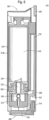
FIG. 1 illustrates side view of an exploded view of an embodiment of a vaporizer in accordance with the disclosure including a battery segment and a cartomizer positioned for connection with the battery segment, where portions of the exterior surfaces removed to illustrate internal components of the vaporizer; -
FIG. 2 illustrates a top view of an embodiment of a vaporizer battery portion; -
FIG. 3 illustrates a perspective view of an embodiment of a vaporizer in accordance with the disclosure; -
FIG. 4 illustrates a perspective view of an embodiment of a vaporizer in accordance with the disclosure; -
FIG. 5 illustrates an exploded perspective view of an embodiment of a vaporizer in accordance with the disclosure; and -
FIG. 6 illustrates an embodiment of a cartomizer portion which may be utilized with embodiments of a vaporizer in accordance with the disclosure. - The following detailed description and the appended drawings describe and illustrate some embodiments of the disclosure for the purpose of enabling one of ordinary skill in the relevant art to make and use these embodiments. As such, the detailed description and illustration of these embodiments are purely illustrative in nature and are in no way intended to limit the scope of the disclosure in any manner. It should also be understood that the drawings are not necessarily to scale and in certain instances details may have been omitted, which are not necessary for an understanding of the embodiments, such as details of fabrication and assembly. In the accompanying drawings, like numerals represent like components.
- In one embodiment of the disclosure, a vaporizer may include a cartomizer and a battery segment. The cartomizer have may have a first cartomizer end and a second cartomizer end. The cartomizer may include an outer cartomizer shell, an internal cavity defined by a portion of the outer cartomizer shell, a heating chamber provided within the outer cartomizer shell and adjacent to the internal cavity, a heating element provided within the heating chamber, a fluid container conformingly dimensioned with the internal cavity, the fluid container insertable and removable from the internal cavity, a mouthpiece provided at or proximate to the second cartomizer end, an airflow channel in fluid communication with the heating chamber and the mouthpiece, cartomizer electrical contacts provided on the outer cartomizer shell proximate the first cartomizer end, and cartomizer electrical circuitry operable to direct an electric current between the cartomizer electrical contacts and the heating element. The battery segment may include an outer battery shell having a first battery end and a second battery end, the cartomizer connectable with the battery segment proximate the first cartomizer end and the first battery end, a battery housed within the outer battery shell, battery electrical contacts provided proximate the first battery end and positioned to contact the cartomizer electrical contacts when the cartomizer is connected to the battery segment, and battery electrical circuitry housed within the battery segment and operable to direct an electrical current between the battery, the battery electrical contacts, the cartomizer electrical contacts, and the heating element.
- In further embodiments of a vaporizer, a portion of the airflow channel is positioned between the outer cartomizer shell and the fluid container. The cartomizer may further include a piercing element proximate the heating chamber and dimensioned to puncture a base end of the fluid container when the fluid container is received in the internal cavity. A self-healing gasket may be provided at or proximate to the base end of the fluid container, the self-healing gasket thereby sealing the base end of the liquid container after the piercing element is removed. The piercing element may be a hollow needle capable of allowing the vaporizable fluid to travel from the fluid container to the heating chamber through the hollow needle. The cartomizer may further include an adjustable air valve provided to allow air to be drawn into the airflow channel. The vaporizer may further include at least one magnet connected to the battery segment proximate the first end of the battery segment, the at least one magnet operable to secure the cartomizer to the battery segment. The vaporizer may further include at least one magnet connected to the cartomizer proximate the first cartomizer end capable of securing the battery segment to the cartomizer. The battery segment may include at least one charging port capable of charging the battery. The at least one charging port may be arranged on the first end of the battery segment. The at least one charging port may include connectors for coupling to complimentary connectors of a charger. The vaporizer may further include a printed circuit board housed in the battery segment and electrically connected to the battery electrical circuitry. The vaporizer may further include at least one illuminable indicator electrically connected to the printed circuit board. The battery segment may be dimensioned to receive the cartomizer proximate the first battery end. The battery segment and the cartomizer may have substantially cylindrical cross-sections.
- With reference to
FIGS. 1-2 , an embodiment of avaporizer 10 may include abattery segment 100, having a cartomizer-side orfirst end 102 and a charger-side orsecond end 104, in addition to acartomizer 200, having a battery-side orfirst end 202 and a mouthpiece-side orsecond end 204. Cartomizer 200 may be operable to hold avaporizable fluid 300.Battery segment 100 may be connectable with thecartomizer 200 through, for example, insertion of the battery-side end 202 of the cartomizer segment into a chamber proximate to the cartomizer-side end 102 of thebattery segment 100. Whilebattery segment 100 is illustrated as a substantially elongate member, other dimensions and shapes are contemplated within the disclosure. For instance, and as best illustrated inFIGS. 3 and 4 , thebattery segment 100 and thecartomizer 200 may be conformingly shaped into a substantially cylindrical or tubular cross-section, with the cartomizer dimensioned to secured on or within a chamber ofbattery segment 100 proximate to the battery-side end 102. This conformed fit betweenbattery segment 100 andcartomizer 200 may operate to ensure proper fitting and coupling ofcartomizer 200 into a chamber ofbattery segment 100. Other cross-section shapes, including for instance a substantially circular cross section for eitherbattery segment 100 orcartomizer 200, are also contemplated within the disclosure. It is further contemplated that eitherbattery segment 100 orcartomizer 200 may be re-dimensioned so that they are not substantially elongate, as shown in the illustrated embodiments. -
Battery segment 100 may include anouter shell 110 for protecting the various components housed internally within at least a portion ofshell 110. One component which may be housed withinshell 110 is abattery 120, which in some embodiments is rechargeable. In embodiments wherebattery 120 is rechargeable, a chargingport 130 may be provided. In the embodiment illustrated inFIG. 1 , chargingport 130 is provided proximate to charger-side 104. Charging port may be charged either through direct contact with an electrical source or, alternatively, through inductive charging. In one embodiment, chargingport 130 may have connectors, such as threadings or magnets, for directly coupling a charger with chargingport 130. For instance, a charger may have male threadings connectable with female threadings provided as part of chargingport 130, or chargingport 130 may have magnets for securing a charger having magnets of opposing polarities. One such charger with magnet couplings is disclosed inU.S. Application No. 14/201,267 . A removable cap could be provided to cover either magnets or threadings so that they are not exposed when not coupled with a charger. The charger may then be connected to a power source, such as through a USB cable or a standard electrical outlet. In another embodiment, chargingport 130 may include inductive wireless technology which allows thebattery 120 to be charged by placing chargingport 130 proximate to an inductive charging pad used for wireless charging. In one embodiment, chargingport 130 is dual-functioning in thatbattery 120 may be charged by either coupling a charger to chargingport 130 or placingbattery segment 100 near an inductive charging pad, for instance settingbattery segment 100 on top of an inductive charging pad. -
Battery segment 100 may include more than one chargingport 130, where for instance a first charging port and a second charging port are concurrently provided. The first charging port may have the ability to chargebattery 120 through a first charging method while the second charging port may have the ability to chargebattery 120 through a second charging method. Either the first or second charging method may be direct charging facilitated by directly coupling the charging port with a charger, and the other charging method may be indirect or inductive charging facilitated by placing the associated charging port proximate to an inductive charging pad. In one example embodiment, a first charging port may be provided proximate to charger-side 104 and may be operable toinductively charge battery 120, while a second charging port may be provided proximate to battery-side 102 and may be operable to directly couple with a charger, which may be receivable within the same chamber which cartomizer 200 is insertable into. As a result, various embodiments ofvaporizer 10 contemplatebattery 120 being rechargeable either through direct coupling of a charger to chargingport 130, through inductive charging from placing an inductive charging source proximate to chargingport 130. - One or
more magnets 140 may be provided in order to secure orcouple battery segment 100 withcartomizer 200 ascartomizer 200 is positioned proximate tomagnets 140.Magnets 140 may secure thecartomizer 200 through a magnetic attraction with eithermagnets 240 included withcartomizer 200 or with metal pieces or strips in lieu ofactive magnets 240. Alternatively,magnets 240 may be provided proximate tobattery side 202 ofcartomizer 200, andmagnets 240 may engage one or more metal strips orpieces 140 in order to establish a magnetic coupling betweencartomizer 200 andbattery segment 100. Other connectors are contemplated within the disclosure in order to couplebattery segment 100 andcartomizer 200 including, for instance, threaded connectors or any other known or to be discovered connector. A snap-fit or friction-fit connection betweencartomizer 200 andbattery segment 100 is also contemplated within the disclosure. - An electronic control system may be provided in order to operate various functions of
vaporizer 10. The electronic control system may include a printed circuit board (PCB) 150, which in one embodiment may be substantially elongate and run through at least a portion of theelongate shell 110. In connection withPCB 150 may be one ormore indicators 152 as well as one or more control buttons or switches 154. A series ofindicators 152, such as the sequentially aligned five (5) indicators shown in the illustrated embodiment ofFIG. 1 andFIG. 3 , may be operable to indicate a charging or power status ofbattery segment 100. The indicators may be illuminable, for instance through one or more light emitting diodes (LEDs) included in eachindicator 152. Accordingly, eachindicator 152 may be composed of one of a series of sequentially drilled holes in a portion ofshell 110, with an LED positioned behind the sequentially drilled holes.Buttons 154 may be capacitive touch buttons, manipulable upon pressure or simple contact by a user, or alternatively may be any known or to be developed buttons operable to control the various functions ofvaporizer 10 through the electronic control system. APCB connection 156 may also be provided as part of the electronic control system.Connection 156 may operate to transmit electrical signals to a coupledcartomizer 200 so that electronically controlled functions ofcartomizer 200 may be operated throughbattery segment 100, including through manipulation ofbuttons 154.Connection 156 may be provided at the base of the chamber proximate to cartomizer-side 102 ofbattery segment 100. Anair switch controller 160 may also be provided and controlled by and throughPCB 150. -
Cartomizer 200 may include anouter shell 210, the interior of which may include afluid chamber 212 for holdingvaporizable fluid 300. Amouthpiece 220 may be provided oncartomizer 200 at or proximate to mouthpiece-end 204. In someembodiments mouthpiece 220 is releasably attachable tocartomizer 200 in order to exposefluid chamber 212 so that user may addadditional fluid 300. Wheremouthpiece 220 is removable,mouthpiece 220 may be attached tocartomizer shell 210 by any known or to be developed connector, including threadings or push-in friction fitting.Cartomizer 200 may be divided into afluid chamber 212 and aheating chamber 214, with the chambers separated by a wall or other barrier. In some embodiments, theheating chamber 214 may be provided proximate to battery-side end 202, whilefluid chamber 212 may be provided proximate to mouthpiece-side end 204. A heating or vaporizingunit 230 may be provided withinheating chamber 214, where the vaporizing unit is operable to receive fluid 300 fromfluid chamber 212 and to heat fluid 300 to a vaporization temperature. Once a vaporization temperature is obtained, fluid 300 transitions to a vapor and may pass through anairflow channel 216 tomouthpiece 220.Airflow channel 216 in one embodiment may be a passageway running betweenfluid chamber 212 andouter shell 210. In another embodiment,airflow channel 216 may be a composed of a tube or other similar structure extending betweenheating chamber 214 andmouthpiece 220, throughfluid chamber 212. An cartomizer electronic control system may also be provided as part ofcartomizer 200, where the cartomizer electronic control system may include aCartomizer PCB 150.Magnets 240 may also be provided withinheating chamber 214. -
FIGS. 3 and 4 illustrate additional embodiments of a vaporizer in accordance with the disclosure.FIG. 5 illustrates an exploded view of a deconstructed vaporizer, in accordance with the disclosure. -
FIG. 6 illustrates an embodiment ofcartomizer 200 which may be connected with embodiments ofbattery segment 100 as part of embodiments ofvaporizer 10, in accordance with the disclosure.Cartomizer 200 may include anouter shell 210 having afirst end 202 and amouthpiece end 204. The interior ofshell 210 may be dimensioned to receive a removable fluid chamber orcapsule 212 havingcapsule walls 212a. Aremovable mouthpiece 220 may be provided oncartomizer 200 at or proximate to mouthpiece-end 204. Proximate tofirst end 202, aheater housing 214 may be provided for holding aheating element 230, which in one embodiment may be a heating coil whose temperature may be elevated to a vaporization temperature upon passing a current through the wound coil. Acoupling component 242 may be provided to facilitate connection withbattery segment 100 as well as for securingheater housing 214. -
Capsule 212 may further include acapsule base 222 and a self-healingrubber gasket 224. Ascapsule 212 is inserted, an end portion ofcapsule 212 may be pierced by a puncturingneedle 232. In some embodiments, such as the illustrated embodiment,needle 232 may puncture a center area ofgasket 224, while in other embodiments needle 232 may puncture a bottom portion ofcapsule wall 212a or, alternatively, thecapsule base 222. In embodiments whereneedle 232 punctures self-healingrubber gasket 224, the self-healing nature ofgasket 224 may allow removal ofcapsule 212 without leaking, thereby permitting multiple insertion and removals without unintended leaking. Once punctured, vaporizable liquid may travel fromcapsule 212 throughneedle 232 toheating element 230 where it may be vaporized to a vaporization temperature and converted from a liquid to an inhalable gas. - An
air side channel 216 may be provided for fluidly connectingmouthpiece 220 andheating element 230. In one embodiment,air channel 216 extends longitudinally along a portion of the length ofouter shell 210 substantially parallel to an insertedcartridge 212. Environmental air from immediately outsidevaporizer 10, may be drawn into an airflow channel throughopening 218, which may be an adjustable air valve. By including an adjustable valve at opening 218, users ofvaporizer 10 may regulate air flow as may be desirable. A greater or fullopen opening 218 may produce significantly larger clouds of vapor, while a smaller or partiallyclosed opening 218 may produce smaller but more concentrated vapor. The air channel may continue to be defined along an internal area ofcartomizer 200 proximate tofirst end 202, which for instance may be a portion ofcoupling component 242, upwards towardsheating element 230, and through agap 226 leading toair side channel 216 and terminating atmouthpiece 220. APCB 250 may be further provided in order to control various components ofcartomizer 200, for instance current control toheating element 230 or operation ofvalve 218. An electrical current may be provided from battery inbattery segment 100 tocartomizer 200 through electrical contacts provided proximate tofirst end 202. - The descriptions set forth above are meant to be illustrative and not limiting. Various modifications of the invention, in addition to those described herein, will be apparent to those skilled in the art from the foregoing description.
-
- 10
- Vaporizer
- 100
- Battery Segment
- 102
- First End
- 104
- Second End
- 110
- Outer Shell
- 120
- Battery
- 130
- Charging Port
- 140
- Magnets
- 150
- Printed Circuit Board
- 152
- Indicators
- 154
- Control Buttons
- 156
- PCB connection
- 160
- Air Switch Controller
- 200
- Cartomizer
- 202
- First End
- 204
- Second End
- 210
- Outer Shell
- 212
- Fluid Chamber
- 212a
- Capsule Walls
- 214
- Heating Chamber
- 216
- Airflow Channel
- 218
- Opening
- 220
- Mouthpiece
- 222
- Capsule Base
- 224
- Rubber Gasket
- 226
- Gap
- 230
- Heating Unit
- 232
- Needle
- 242
- Coupling Component
- 240
- Magnets
- 250
- Printed Circuit Board
- 300
- Vaporizable Fluid
Claims (13)
- A vaporizer comprising:a cartomizer (200) having a first cartomizer end and a second cartomizer end, the cartomizer including;an outer cartomizer shell (110, 210),an internal cavity defined by a portion of the outer cartomizer shell, the internal cavity having a fluid chamber (212) for holding vaporizable fluid,a heating chamber (214) provided within the outer cartomizer shell and adjacent to the internal cavity,a heating element (230) provided within the heating chamber,a mouthpiece (220) provided at or proximate to the second cartomizer end,an airflow channel (216) in fluid communication with the heating chamber and the mouthpiece,cartomizer electrical contacts provided on the outer cartomizer shell proximate the first cartomizer end, andcartomizer electrical circuitry operable to direct an electric current between the cartomizer electrical contacts and the heating element; anda battery segment (100) including:an outer battery shell having a first battery end, a second battery end, a longitudinal axis extending between the first battery end and the second battery end, and a longitudinal wall extending along the longitudinal axis, the cartomizer connectable with the battery segment proximate the first cartomizer end and the first battery end,a battery (120) housed within the outer battery shell,battery electrical contacts provided proximate the first battery end and positioned to contact the cartomizer electrical contacts when the cartomizer is connected to the battery segment,battery electrical circuitry housed within the battery segment and operable to direct an electrical current between the battery, the battery electrical contacts, the cartomizer electrical contacts, and the heating element, andan elongated printed circuit board (150, 250) housed in the battery segment and electrically connected to the battery electrical circuitry, wherein the printed circuit board extends through at least a portion of the outer battery shell between the battery and the longitudinal wall of the outer battery shell.
- The vaporizer of claim 1, wherein a portion of the airflow channel (216) is positioned between the outer cartomizer shell and the fluid chamber.
- The vaporizer of claim 1 or 2, wherein the cartomizer further includes a piercing element proximate the heating chamber and dimensioned to puncture a base end of the fluid chamber when the fluid chamber is received in the internal cavity.
- The vaporizer of claim 3, wherein a self-healing gasket (224) is provided at or proximate to the base end of the fluid chamber, the self-healing gasket thereby sealing the base end of the fluid chamber after the piercing element is removed.
- The vaporizer of claim 3 or 4, wherein the piercing element is a hollow needle (232) capable of allowing the vaporizable fluid to travel from the fluid chamber to the heating chamber through the hollow needle.
- The vaporizer of one of the preceding claims, further comprising at least one magnet (140) connected to the battery segment proximate the first end of the battery segment, the at least one magnet operable to secure the cartomizer to the battery segment.
- The vaporizer of one of the preceding claims, further comprising at least one magnet (240) connected to the cartomizer proximate the first cartomizer end capable of securing the battery segment to the cartomizer.
- The vaporizer of one of the preceding claims, wherein the battery segment includes at least one charging port (130) capable of charging the battery.
- The vaporizer of claim 8, wherein the at least one charging port (130) is arranged on the first end of the battery segment.
- The vaporizer of claim 8 or 9, wherein the at least one charging port (130) includes connectors for coupling to complimentary connectors of a charger.
- The vaporizer of one of the preceding claims, further comprising at least one illuminable indicator (152) electrically connected to the printed circuit board.
- The vaporizer of one of the preceding claims, wherein the battery segment (100) is dimensioned to receive the cartomizer proximate the first battery end.
- The vaporizer of claim 12, wherein the battery segment and the cartomizer have substantially cylindrical cross-sections.
Applications Claiming Priority (5)
| Application Number | Priority Date | Filing Date | Title |
|---|---|---|---|
| US201461987196P | 2014-05-01 | 2014-05-01 | |
| US29/498,556 USD750320S1 (en) | 2014-08-05 | 2014-08-05 | Vaporizer |
| US201462038785P | 2014-08-18 | 2014-08-18 | |
| PCT/US2015/028909 WO2015168631A1 (en) | 2014-05-01 | 2015-05-01 | Vaporizer |
| EP15786819.1A EP3137141B1 (en) | 2014-05-01 | 2015-05-01 | Vaporizer |
Related Parent Applications (1)
| Application Number | Title | Priority Date | Filing Date |
|---|---|---|---|
| EP15786819.1A Division EP3137141B1 (en) | 2014-05-01 | 2015-05-01 | Vaporizer |
Publications (2)
| Publication Number | Publication Date |
|---|---|
| EP3897073A1 EP3897073A1 (en) | 2021-10-20 |
| EP3897073B1 true EP3897073B1 (en) | 2023-11-01 |
Family
ID=54354179
Family Applications (2)
| Application Number | Title | Priority Date | Filing Date |
|---|---|---|---|
| EP21178682.7A Active EP3897073B1 (en) | 2014-05-01 | 2015-05-01 | Vaporizer |
| EP15786819.1A Active EP3137141B1 (en) | 2014-05-01 | 2015-05-01 | Vaporizer |
Family Applications After (1)
| Application Number | Title | Priority Date | Filing Date |
|---|---|---|---|
| EP15786819.1A Active EP3137141B1 (en) | 2014-05-01 | 2015-05-01 | Vaporizer |
Country Status (3)
| Country | Link |
|---|---|
| US (1) | US20150313287A1 (en) |
| EP (2) | EP3897073B1 (en) |
| WO (1) | WO2015168631A1 (en) |
Families Citing this family (82)
| Publication number | Priority date | Publication date | Assignee | Title |
|---|---|---|---|---|
| US20160345631A1 (en) | 2005-07-19 | 2016-12-01 | James Monsees | Portable devices for generating an inhalable vapor |
| US20150328415A1 (en) * | 2014-05-19 | 2015-11-19 | R.J. Reynolds Tobacco Company | Cartridge vaporizer in a personal vaporizer unit |
| US10279934B2 (en) | 2013-03-15 | 2019-05-07 | Juul Labs, Inc. | Fillable vaporizer cartridge and method of filling |
| US10980273B2 (en) | 2013-11-12 | 2021-04-20 | VMR Products, LLC | Vaporizer, charger and methods of use |
| US10076139B2 (en) | 2013-12-23 | 2018-09-18 | Juul Labs, Inc. | Vaporizer apparatus |
| US20160366947A1 (en) | 2013-12-23 | 2016-12-22 | James Monsees | Vaporizer apparatus |
| USD825102S1 (en) | 2016-07-28 | 2018-08-07 | Juul Labs, Inc. | Vaporizer device with cartridge |
| USD842536S1 (en) | 2016-07-28 | 2019-03-05 | Juul Labs, Inc. | Vaporizer cartridge |
| US10159282B2 (en) | 2013-12-23 | 2018-12-25 | Juul Labs, Inc. | Cartridge for use with a vaporizer device |
| DE202014011265U1 (en) | 2013-12-23 | 2018-12-06 | Juul Labs Uk Holdco Limited | Systems for an evaporation device |
| US10058129B2 (en) | 2013-12-23 | 2018-08-28 | Juul Labs, Inc. | Vaporization device systems and methods |
| TWI751467B (en) | 2014-02-06 | 2022-01-01 | 美商尤爾實驗室有限公司 | A device for generating an inhalable aerosol and a separable cartridge for use therewith |
| US10709173B2 (en) | 2014-02-06 | 2020-07-14 | Juul Labs, Inc. | Vaporizer apparatus |
| US10287154B2 (en) | 2014-02-28 | 2019-05-14 | Ayr Ltd. | Electronic vaporiser system |
| US11085550B2 (en) | 2014-02-28 | 2021-08-10 | Ayr Ltd. | Electronic vaporiser system |
| US10136674B2 (en) | 2014-02-28 | 2018-11-27 | Beyond Twenty Ltd. | Electronic vaporiser system |
| GB201413028D0 (en) | 2014-02-28 | 2014-09-03 | Beyond Twenty Ltd | Beyond 5 |
| US10091839B2 (en) | 2014-02-28 | 2018-10-02 | Beyond Twenty Ltd. | Electronic vaporiser system |
| US10588176B2 (en) | 2014-02-28 | 2020-03-10 | Ayr Ltd. | Electronic vaporiser system |
| US20160366946A1 (en) | 2014-02-28 | 2016-12-22 | Beyond Twenty Ltd. | Electronic vaporiser system |
| USD762003S1 (en) | 2014-07-25 | 2016-07-19 | Pax Labs, Inc. | Electronic vaporization device |
| CA160775S (en) | 2014-08-11 | 2015-09-29 | Ploom Inc | Electronic vaporization device with cartridge |
| RU2709926C2 (en) | 2014-12-05 | 2019-12-23 | Джуул Лэбз, Инк. | Calibrated dose control |
| PL3256387T3 (en) * | 2015-02-13 | 2020-10-19 | Fontem Holdings 1 B.V. | Filling system for electronic smoking devices |
| USD874059S1 (en) | 2015-04-22 | 2020-01-28 | Altria Client Servies Llc | Electronic vaping device |
| US10064432B2 (en) | 2015-04-22 | 2018-09-04 | Altria Client Services Llc | Pod assembly, dispensing body, and E-vapor apparatus including the same |
| CN107750129B (en) | 2015-04-22 | 2020-09-25 | 奥驰亚客户服务有限责任公司 | Pod assembly, dispensing body and electronic cigarette device including same |
| US9999258B2 (en) | 2015-04-22 | 2018-06-19 | Altria Client Services Llc | Pod assembly, dispensing body, and e-vapor apparatus including the same |
| USD874720S1 (en) | 2015-04-22 | 2020-02-04 | Altria Client Services, Llc | Pod for an electronic vaping device |
| US10104913B2 (en) | 2015-04-22 | 2018-10-23 | Altria Client Services Llc | Pod assembly, dispensing body, and E-vapor apparatus including the same |
| USD980507S1 (en) | 2015-04-22 | 2023-03-07 | Altria Client Services Llc | Electronic vaping device |
| US10701981B2 (en) | 2015-04-22 | 2020-07-07 | Altria Client Services Llc | Pod assembly and e-vapor apparatus including the same |
| AU2016313955B2 (en) | 2015-09-01 | 2021-01-28 | Ayr Ltd | Electronic vaporiser system |
| GB2544493B (en) * | 2015-11-17 | 2020-06-17 | Nerudia Ltd | A dispenser for dispensing a liquid for a substitute smoking device |
| USD858870S1 (en) | 2016-02-08 | 2019-09-03 | Juul Labs, Inc. | Vaporizer cartridge |
| USD861975S1 (en) | 2016-02-08 | 2019-10-01 | Juul Labs, Inc. | Vaporizer device with cartridges |
| WO2017139595A1 (en) | 2016-02-11 | 2017-08-17 | Pax Labs, Inc. | Fillable vaporizer cartridge and method of filling |
| EA039727B1 (en) | 2016-02-11 | 2022-03-04 | Джуул Лэбз, Инк. | Securely attaching cartridges for vaporizer devices |
| MX2018010186A (en) | 2016-02-25 | 2019-01-14 | Juul Labs Inc | Vaporization device control systems and methods. |
| US10405582B2 (en) | 2016-03-10 | 2019-09-10 | Pax Labs, Inc. | Vaporization device with lip sensing |
| GB201605101D0 (en) * | 2016-03-24 | 2016-05-11 | Nicoventures Holdings Ltd | Electronic vapour provision system |
| GB201605102D0 (en) | 2016-03-24 | 2016-05-11 | Nicoventures Holdings Ltd | Mechanical connector for electronic vapour provision system |
| CN209768982U (en) * | 2016-05-03 | 2019-12-13 | 惠州市吉瑞科技有限公司深圳分公司 | Electronic cigarette |
| USD849996S1 (en) | 2016-06-16 | 2019-05-28 | Pax Labs, Inc. | Vaporizer cartridge |
| USD851830S1 (en) | 2016-06-23 | 2019-06-18 | Pax Labs, Inc. | Combined vaporizer tamp and pick tool |
| USD848057S1 (en) | 2016-06-23 | 2019-05-07 | Pax Labs, Inc. | Lid for a vaporizer |
| USD836541S1 (en) | 2016-06-23 | 2018-12-25 | Pax Labs, Inc. | Charging device |
| USD854238S1 (en) | 2016-07-29 | 2019-07-16 | Pax Labs, Inc. | Cover for a vaporizer device |
| USD858872S1 (en) | 2016-08-08 | 2019-09-03 | Pax Labs, Inc. | Case for a vaporizer cartridge |
| US11660403B2 (en) | 2016-09-22 | 2023-05-30 | Juul Labs, Inc. | Leak-resistant vaporizer device |
| US20180110941A1 (en) * | 2016-10-21 | 2018-04-26 | Brian Smith | Pearl precision medical dosing vaporizer fully interchangeable |
| KR102380105B1 (en) | 2016-12-02 | 2022-03-28 | 브이엠알 프로덕츠 엘엘씨 | combination carburetor |
| KR20190107017A (en) | 2016-12-12 | 2019-09-18 | 브이엠알 프로덕츠 엘엘씨 | carburetor |
| CA3046954C (en) | 2016-12-12 | 2024-01-02 | Vmr Products Llc | Refillable cartridge for vaporizer |
| US10603459B2 (en) | 2017-07-20 | 2020-03-31 | Eric Kotch | Variable viscosity vaporizer cartridge |
| USD887632S1 (en) | 2017-09-14 | 2020-06-16 | Pax Labs, Inc. | Vaporizer cartridge |
| PL3530130T3 (en) * | 2018-02-27 | 2021-05-04 | Imperial Tobacco Ventures Limited | Smoking apparatus |
| GB201805234D0 (en) * | 2018-03-29 | 2018-05-16 | Nicoventures Trading Ltd | Aerosol generating device |
| CN108506961A (en) * | 2018-04-04 | 2018-09-07 | 深圳市捷美斯实业有限公司 | A kind of separate type fills cigar lighter |
| CN208264070U (en) * | 2018-04-04 | 2018-12-21 | 深圳市捷美斯实业有限公司 | A kind of vehicle-mounted cigarette lighter |
| CN208264069U (en) * | 2018-04-04 | 2018-12-21 | 深圳市捷美斯实业有限公司 | A kind of two-in-one vehicle-mounted cigarette lighter |
| US10888125B2 (en) | 2018-06-27 | 2021-01-12 | Juul Labs, Inc. | Vaporizer device with subassemblies |
| GB2584578B (en) * | 2018-06-27 | 2022-12-21 | Juul Labs Inc | Vaporizer device |
| US10791767B2 (en) | 2018-10-12 | 2020-10-06 | Rai Strategic Holdings, Inc. | Connectors for forming electrical and mechanical connections between interchangeable units in an aerosol delivery system |
| US11291249B2 (en) | 2018-10-12 | 2022-04-05 | Rai Strategic Holdings, Inc. | Aerosol delivery device with visible indicator |
| US11678700B2 (en) | 2018-10-12 | 2023-06-20 | Rai Strategic Holdings, Inc. | Aerosol delivery device with visible indicator |
| US10939702B2 (en) | 2018-10-12 | 2021-03-09 | Rai Strategic Holdings, Inc. | Connectors for forming electrical and mechanical connections between interchangeable units in an aerosol delivery system |
| US11588287B2 (en) | 2018-10-12 | 2023-02-21 | Rai Strategic Holdings, Inc. | Aerosol delivery device with improved connectivity, airflow, and aerosol paths |
| WO2020097341A1 (en) | 2018-11-08 | 2020-05-14 | Juul Labs, Inc. | Cartridges for vaporizer devices |
| US11156766B2 (en) | 2018-11-19 | 2021-10-26 | Rai Strategic Holdings, Inc. | Aerosol delivery device |
| US11614720B2 (en) | 2018-11-19 | 2023-03-28 | Rai Strategic Holdings, Inc. | Temperature control in an aerosol delivery device |
| US11372153B2 (en) | 2018-11-19 | 2022-06-28 | Rai Strategic Holdings, Inc. | Cartridge orientation for selection of a control function in a vaporization system |
| US11592793B2 (en) | 2018-11-19 | 2023-02-28 | Rai Strategic Holdings, Inc. | Power control for an aerosol delivery device |
| WO2020117338A1 (en) * | 2018-12-06 | 2020-06-11 | Guo Xingchen | Portable smoking cessation device with replaceable battery |
| JP2022515121A (en) * | 2018-12-18 | 2022-02-17 | ジュール・ラブズ・インコーポレイテッド | Vaporizer device |
| US11253001B2 (en) | 2019-02-28 | 2022-02-22 | Juul Labs, Inc. | Vaporizer device with vaporizer cartridge |
| USD943161S1 (en) | 2019-11-14 | 2022-02-08 | Juul Labs, Inc. | Vaporizer device |
| USD943160S1 (en) | 2019-11-14 | 2022-02-08 | Juul Labs, Inc. | Vaporizer device |
| USD943159S1 (en) | 2019-11-14 | 2022-02-08 | Juul Labs, Inc. | Component for a vaporizer cartridge |
| USD943158S1 (en) | 2019-11-14 | 2022-02-08 | Juul Labs, Inc. | Vaporizer cartridge |
| KR20230080416A (en) * | 2020-10-08 | 2023-06-07 | 제이티 인터내셔널 소시에떼 아노님 | aerosol generating device |
| US11856986B2 (en) | 2020-10-19 | 2024-01-02 | Rai Strategic Holdings, Inc. | Customizable panel for aerosol delivery device |
Family Cites Families (12)
| Publication number | Priority date | Publication date | Assignee | Title |
|---|---|---|---|---|
| US4569136A (en) * | 1984-01-19 | 1986-02-11 | Loring Martha T | Method and apparatus for gratifying excessive oral needs |
| CA2729601C (en) * | 2008-02-29 | 2013-09-24 | Yunqiang Xiu | Electronic simulated cigarette & atomization fluid and electronic simulated cigarette utensil & smoke fluid capsule |
| AT507631B1 (en) * | 2008-11-26 | 2012-05-15 | Haas Rouven Mag | DEVICE FOR INTAKING POWDER OR GRANULATE MATERIAL AND CAPSULE THEREFOR |
| US20150328415A1 (en) * | 2014-05-19 | 2015-11-19 | R.J. Reynolds Tobacco Company | Cartridge vaporizer in a personal vaporizer unit |
| CN102326869B (en) * | 2011-05-12 | 2013-04-03 | 陈志平 | Atomization nozzle of electronic atomization inhaler |
| US9498588B2 (en) * | 2011-12-14 | 2016-11-22 | Atmos Nation, LLC | Portable pen sized electric herb vaporizer with ceramic heating chamber |
| WO2013138384A2 (en) * | 2012-03-12 | 2013-09-19 | Uptoke Llc | Electronic vaporizing device and methods for use |
| CN202566289U (en) * | 2012-04-20 | 2012-12-05 | 刘翔 | Electronic cigarette |
| BR122020000251B1 (en) * | 2012-04-26 | 2021-08-10 | Fontem Holdings 1 B.V. | CARTRIDGE UNIT |
| CN203234036U (en) * | 2012-07-23 | 2013-10-16 | 刘秋明 | Electronic cigarette |
| CN103349363A (en) * | 2013-06-15 | 2013-10-16 | 深圳市合元科技有限公司 | Electronic cigarette |
| CN103750571B (en) * | 2014-01-15 | 2016-07-20 | 林光榕 | Electronic cigarette and manufacture method and electrolyte filling method |
-
2015
- 2015-05-01 EP EP21178682.7A patent/EP3897073B1/en active Active
- 2015-05-01 US US14/702,419 patent/US20150313287A1/en not_active Abandoned
- 2015-05-01 WO PCT/US2015/028909 patent/WO2015168631A1/en active Application Filing
- 2015-05-01 EP EP15786819.1A patent/EP3137141B1/en active Active
Also Published As
| Publication number | Publication date |
|---|---|
| EP3897073A1 (en) | 2021-10-20 |
| EP3137141A4 (en) | 2018-01-31 |
| US20150313287A1 (en) | 2015-11-05 |
| WO2015168631A1 (en) | 2015-11-05 |
| EP3137141B1 (en) | 2021-06-23 |
| EP3137141A1 (en) | 2017-03-08 |
Similar Documents
| Publication | Publication Date | Title |
|---|---|---|
| EP3897073B1 (en) | Vaporizer | |
| US20170071256A1 (en) | Vaporizer | |
| US11606981B2 (en) | Vaporizer | |
| US10893704B2 (en) | Vaporizer | |
| EP3469934B1 (en) | Vaporizer | |
| US9781953B2 (en) | Vaporizer with cover sleeve | |
| US20120318882A1 (en) | Vapor delivery devices | |
| CN111082480A (en) | Vaporization equipment charger | |
| US20170360090A1 (en) | Smart Phone E-Cigarette | |
| KR200474117Y1 (en) | Electrode connecting structure for inhaling apparatus |
Legal Events
| Date | Code | Title | Description |
|---|---|---|---|
| PUAI | Public reference made under article 153(3) epc to a published international application that has entered the european phase |
Free format text: ORIGINAL CODE: 0009012 |
|
| STAA | Information on the status of an ep patent application or granted ep patent |
Free format text: STATUS: THE APPLICATION HAS BEEN PUBLISHED |
|
| AC | Divisional application: reference to earlier application |
Ref document number: 3137141 Country of ref document: EP Kind code of ref document: P |
|
| AK | Designated contracting states |
Kind code of ref document: A1 Designated state(s): AL AT BE BG CH CY CZ DE DK EE ES FI FR GB GR HR HU IE IS IT LI LT LU LV MC MK MT NL NO PL PT RO RS SE SI SK SM TR |
|
| B565 | Issuance of search results under rule 164(2) epc |
Effective date: 20210922 |
|
| STAA | Information on the status of an ep patent application or granted ep patent |
Free format text: STATUS: REQUEST FOR EXAMINATION WAS MADE |
|
| 17P | Request for examination filed |
Effective date: 20220414 |
|
| RBV | Designated contracting states (corrected) |
Designated state(s): AL AT BE BG CH CY CZ DE DK EE ES FI FR GB GR HR HU IE IS IT LI LT LU LV MC MK MT NL NO PL PT RO RS SE SI SK SM TR |
|
| REG | Reference to a national code |
Ref country code: HK Ref legal event code: DE Ref document number: 40062634 Country of ref document: HK |
|
| GRAP | Despatch of communication of intention to grant a patent |
Free format text: ORIGINAL CODE: EPIDOSNIGR1 |
|
| STAA | Information on the status of an ep patent application or granted ep patent |
Free format text: STATUS: GRANT OF PATENT IS INTENDED |
|
| RIC1 | Information provided on ipc code assigned before grant |
Ipc: A61M 11/04 20060101ALI20230504BHEP Ipc: A24F 40/485 20200101ALI20230504BHEP Ipc: A24F 40/42 20200101ALI20230504BHEP Ipc: A61M 15/06 20060101ALI20230504BHEP Ipc: H05B 3/46 20060101AFI20230504BHEP |
|
| INTG | Intention to grant announced |
Effective date: 20230516 |
|
| GRAS | Grant fee paid |
Free format text: ORIGINAL CODE: EPIDOSNIGR3 |
|
| GRAA | (expected) grant |
Free format text: ORIGINAL CODE: 0009210 |
|
| STAA | Information on the status of an ep patent application or granted ep patent |
Free format text: STATUS: THE PATENT HAS BEEN GRANTED |
|
| AC | Divisional application: reference to earlier application |
Ref document number: 3137141 Country of ref document: EP Kind code of ref document: P |
|
| AK | Designated contracting states |
Kind code of ref document: B1 Designated state(s): AL AT BE BG CH CY CZ DE DK EE ES FI FR GB GR HR HU IE IS IT LI LT LU LV MC MK MT NL NO PL PT RO RS SE SI SK SM TR |
|
| RAP3 | Party data changed (applicant data changed or rights of an application transferred) |
Owner name: VMR PRODUCTS, LLC |
|
| REG | Reference to a national code |
Ref country code: GB Ref legal event code: FG4D |
|
| RIN1 | Information on inventor provided before grant (corrected) |
Inventor name: FAJARDO, ARTURO Inventor name: LU, YIFENG Inventor name: RECIO, DAN Inventor name: VERLEUR, JAN ANDRIES |
|
| REG | Reference to a national code |
Ref country code: CH Ref legal event code: EP |
|
| REG | Reference to a national code |
Ref country code: DE Ref legal event code: R096 Ref document number: 602015086440 Country of ref document: DE |
|
| REG | Reference to a national code |
Ref country code: IE Ref legal event code: FG4D |
|
| REG | Reference to a national code |
Ref country code: GB Ref legal event code: 732E Free format text: REGISTERED BETWEEN 20240104 AND 20240110 |
|
| REG | Reference to a national code |
Ref country code: LT Ref legal event code: MG9D |
|
| REG | Reference to a national code |
Ref country code: NL Ref legal event code: MP Effective date: 20231101 |
|
| PG25 | Lapsed in a contracting state [announced via postgrant information from national office to epo] |
Ref country code: GR Free format text: LAPSE BECAUSE OF FAILURE TO SUBMIT A TRANSLATION OF THE DESCRIPTION OR TO PAY THE FEE WITHIN THE PRESCRIBED TIME-LIMIT Effective date: 20240202 |
|
| PG25 | Lapsed in a contracting state [announced via postgrant information from national office to epo] |
Ref country code: IS Free format text: LAPSE BECAUSE OF FAILURE TO SUBMIT A TRANSLATION OF THE DESCRIPTION OR TO PAY THE FEE WITHIN THE PRESCRIBED TIME-LIMIT Effective date: 20240301 |